

Page 1

CTP Series Circuit to Packet Platforms
CTP150 Circuit to Packet Platform
Quick Start Guide
April 2010
Part Number: 530-033774
Revision 01
This document describes how to install the Juniper Networks ® CTP150 Circuit to
Packet Platform.
Contents
CTP150 Platform Quick Start Description ........................................................3
Step 1: Prepare the Site ...................................................................................3
Before You Unpack the Platform ...............................................................3
Unpack the Platform .................................................................................3
Inspect the Components and Accessories .................................................4
If You Detect or Suspect Damage ..............................................................4
Step 2: Install the Platform ..............................................................................4
Before You Begin Installation ....................................................................4
Option: Install the Platform in Freestanding Mode ....................................5
Option: Install the Platform in a Rack .......................................................5
Step 3: Install Modules and Other Components ...............................................5
Protect Modules and Slots .........................................................................6
Required Tools and Safety Items for Installation .......................................6
Safety Guidelines for Installing Modules ....................................................6
Install an Interface Module ........................................................................7
Install CompactFlash Card and Replace Drive ...........................................8
Step 4: Connect Cables ....................................................................................9
Required Tools and Wires for Cabling .......................................................9
Connect the Management Console ............................................................9
Connect the Timing Port .........................................................................10
Connect the Serial Interface Module .......................................................10
Connect the T1/E1 Interface Module .......................................................10
■ 1
Page 2

CTP150 Platform Quick Start Guide
Step 5: Access ...............................................................................................11
Console Access .......................................................................................11
Direct Access ..........................................................................................11
HyperTerminal Access ............................................................................12
SSH Access .............................................................................................12
Step 6: Power On ..........................................................................................13
Safety Warnings ............................................................................................15
Compliance Statements .................................................................................16
Federal Communications Commission (FCC) Statement .........................16
FCC Requirements for Consumer Products .............................................16
Food and Drug Administration, Center for Devices and Radiological
Health ..............................................................................................17
Canadian Department of Communications Radio Interference
Regulations .......................................................................................17
Industry Canada Notice CS-03 ................................................................17
DOC Explanatory Notes: Equipment Attachment Limitations .................18
EC Declaration of Conformity .................................................................18
CTP Platform Documentation and Release Notes ..........................................21
Requesting Technical Support .......................................................................21
Self-Help Online Tools and Resources .....................................................21
Opening a Case with JTAC ......................................................................22
Revision History ............................................................................................22
2 ■
Page 3

CTP150 Platform Quick Start Description
This Quick Start contains information you need to install and access the CTP150
platform. For complete installation instructions, see the CTP150 Platform Hardware
Documentation at http://www.juniper.net/techpubs/.
WARNING: This Quick Start contains a summary of safety warnings in “Safety
Warnings” on page 15. For a complete list of warnings for this router, including
translations, see the CTP150 Platform Hardware Documentation at
http://www.juniper.net/techpubs/.
Juniper Networks Circuit to Packet (CTP) products provide advanced technology and
features required to reliably transport legacy time-division multiplexing (TDM) and
other circuit-based applications across next-generation IP networks. CTP platforms
create an IP packet flow from a serial data or analog voice connection at one end
and provide the necessary processing to recreate the serial bit stream or analog signal
from the received packet flow at the other end.
CTP150 Platform Quick Start Description
CTP platforms provide compact and lightweight chassis, high port density, and
multiple Ethernet interfaces. Each CTP platform runs the CTP operating system
(CTPOS) and can be managed by CTPView, a secure, Web-based management tool
for provisioning, managing, running diagnostics, monitoring, and reporting on all
CTP platform devices and circuits in the network.
Step 1: Prepare the Site
■ Before You Unpack the Platform on page 3
■ Unpack the Platform on page 3
■ Inspect the Components and Accessories on page 4
■ If You Detect or Suspect Damage on page 4
Before You Unpack the Platform
Before you begin unpacking the platform, be sure you have the following tools:
■ No. 2 Phillips screwdriver
■ Utility knife
■ Two people to assist in lifting
Unpack the Platform
Depending on the platform, it may be delivered boxed, bolted, and strapped to a
skid. For your convenience, we recommend that you unpack the device in the location
where you want to install it.
CTP150 Platform Quick Start Description ■ 3
Page 4

CTP150 Platform Quick Start Guide
To unpack the device:
1. Cut the two straps that secure the carton to the skid, open the carton from the
top, and remove the box of accessories that sits on top of the device.
2. Unlock the four plastic clips that hold the box to the skid by squeezing them in
their center and pulling out, and then lift the carton off the device.
3. Remove the three screws that attach each of the two L-brackets to the device.
4. To avoid scratching the device when removing it from the skid, detach one of
the L-brackets from the skid by removing the three screws.
Inspect the Components and Accessories
After you remove the equipment from the shipping containers:
■ Confirm the contents of each container.
■ Inspect all external surfaces and external connectors for visible signs of damage.
■ Inspect all accessories shipped with each unit.
■ Document any damage noted during your inspection.
■ Confirm that the device has the correct number and type of modules for your
ordered configuration.
If You Detect or Suspect Damage
If you detect or suspect damage to any equipment:
■ Contact the shipper responsible for delivery, and formally report the damage.
■ Contact your Juniper Networks sales representative or reseller.
Step 2: Install the Platform
■ Before You Begin Installation on page 4
■ Option: Install the Platform in Freestanding Mode on page 5
■ Option: Install the Platform in a Rack on page 5
Before You Begin Installation
Before installing the device:
■ Have a plan for installing the device that takes into consideration future
■ Have the tools and accessories needed to complete the installation.
■ Be sure that the space requirement of 3 feet (90 cm) behind the device or rack
4 ■ Step 2: Install the Platform
expansion.
is met. Do not block air vents on the front or back of the router.
Page 5

■ Prepare the equipment racks by measuring and marking space for each device
and plenum you plan to install.
■ See the “Safety Warnings” on page 15
Option: Install the Platform in Freestanding Mode
When installing the device on a table top or in any other freestanding mode, be sure
to leave enough space around the device for adequate ventilation. Position the chassis
with easy access to the connections that it needs for power, local communications,
and remote communications.
WARNING: Two people are required to lift the device.
CAUTION: To prevent electrostatic damage to the device and its components, make
sure persons handling the device wear an antistatic device.
Step 3: Install Modules and Other Components
Option: Install the Platform in a Rack
To install the device in a rack, you need:
■ Phillips screwdriver
■ Four 10-32 x 3/8 Phillips screws for each device to be installed
To install the device in the rack:
1. With one person standing on the left side of the device and another standing on
the right side, lift the device into the rack.
2. Position the device in its designated location in the equipment rack. Make sure
the holes of the mounting brackets align evenly with the holes of the equipment
rack on both sides.
3. Starting at the bottom of the device, have the second person secure the device
in the equipment rack by using the 10-32 x 3/8 Phillips screws.
Step 3: Install Modules and Other Components
■ Protect Modules and Slots on page 6
■ Required Tools and Safety Items for Installation on page 6
■ Safety Guidelines for Installing Modules on page 6
■ Install an Interface Module on page 7
■ Install CompactFlash Card and Replace Drive on page 8
Step 3: Install Modules and Other Components ■ 5
Page 6

CTP150 Platform Quick Start Guide
Protect Modules and Slots
To protect the modules, other components, and slots when installing components,
observe the following guidelines:
CAUTION: When handling components, use an antistatic wrist strap connected to
one of the device's ESD grounding jacks, or to another grounding device. This action
helps to protect the module from damage by electrostatic discharge.
CAUTION: Always handle a module by its edges. Do not touch the components, pins,
leads, or solder connections.
CAUTION: If you meet strong resistance when attempting to seat a module using
the ejectors, remove it from the chassis and confirm that the slot is designed to hold
the module. Also, be sure that you have aligned the left and right edges in the correct
matching module guides.
CAUTION: Be sure to cover every empty slot with a blank filler panel to protect the
device from dust or other foreign substances and to ensure proper device cooling.
CAUTION: Do not discard the antistatic bag. When a module is not in use, store it
in an antistatic bag.
Required Tools and Safety Items for Installation
You need the following tools to install a CTP platform module:
■ Phillips screwdriver
■ Flathead screwdriver
■ ESD wrist strap or other grounding device
Safety Guidelines for Installing Modules
Before and during the installation process, observe the following warnings.
WARNING: Do not work on the device or connect or disconnect cables during lightning
activity.
6 ■ Step 3: Install Modules and Other Components
Page 7
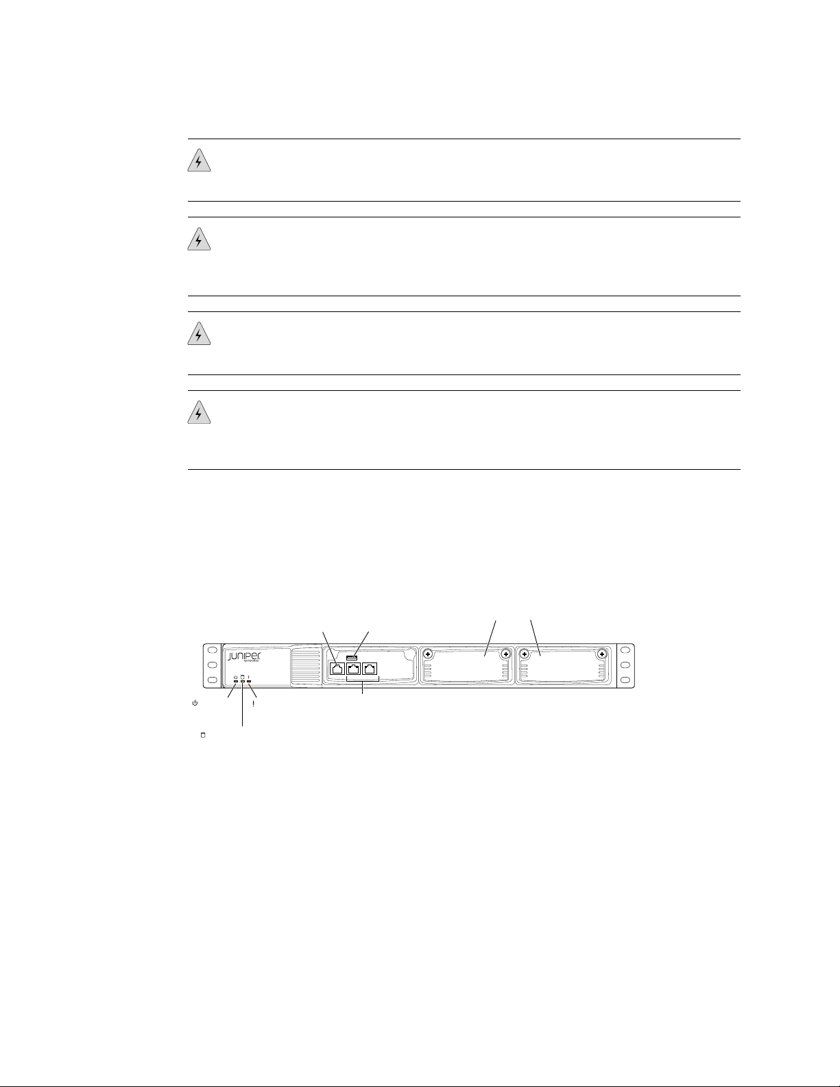
CTP150
g004480
CONSOLEETH1 ETH0
Power
LED
Hardware
LED
Serial
Console port
Traffic
interfaces:
Two copper Ethernet ports
(10/100/1000 Mbps)
USB
port
Flash disk LED
Interface module slots
Step 3: Install Modules and Other Components
WARNING: Be sure circuit breakers for the power source are in the OFF position
before attaching power cables.
WARNING: Remove jewelry (including rings, necklaces, and watches) before working
on equipment that is connected to power lines. Metal objects heat up when connected
to power and ground and can cause serious burns or become welded to the terminals.
WARNING: Do not insert any metal object, such as a screwdriver, into an open slot
or the midplane. Doing so can cause electric shock and serious burns.
WARNING: Never attempt to repair parts of modules yourself. Only trained customer
service personnel are authorized to service parts. Call Juniper Networks Customer
Service to make arrangements to return defective modules for repair.
Install an Interface Module
The CTP150 platform has two possible interface modules, the serial or T1/E1 interface
module, that fit into the slots on the right side of the chassis (see Figure 1 on page 7).
Figure 1: Interface Module Locations in the CTP150 Chassis
To install an interface module:
1. Ground yourself by using an antistatic wrist strap or other device, and connect
it to one of the ESD grounding jacks, or to some other grounding device.
2. Choose the slot where you want to insert the module.
3. With a Phillips screwdriver, loosen the screws that secure the blank filler panel
covering the empty chassis slot, if present, and remove the filler panel.
4. Remove the module from its antistatic bag, being careful not to touch module
components, pins, leads, or solder connections.
5. Verify that the ejectors are in the open position (facing outward).
Step 3: Install Modules and Other Components ■ 7
Page 8

g004481
Fans Compact
Flash drive
Handle
AC power
cord inlet
Ejector lever
CTP150 Platform Quick Start Guide
6. Guide the module into the chassis by placing it between the guides of the selected
CAUTION: If you meet strong resistance when attempting to seat the module using
the ejectors, remove it from the chassis, and confirm that the slot is designed to hold
the component. Also, be sure that you have aligned the left and right edges in the
correct matching tracks.
7. Insert the module into the midplane by simultaneously pressing both ejectors
8. Tighten the module's captive screws using a Phillips screwdriver.
NOTE: Tighten the captive screws completely before installing an adjacent module
so that proper electromagnetic interference (EMI) gasket compression occurs. Failure
to do this can make it difficult to install adjacent modules.
slot and pushing the module until it stops.
The module stops sliding when the ejectors make contact with the chassis.
inward and exerting forward pressure on the module. The small red release
buttons should click into place.
Install CompactFlash Card and Replace Drive
The CTP150 model has a removable Type II CompactFlash card. The device should
be powered off when you insert or remove the Flash drive. Figure 2 on page 8
shows the Flash drive on the rear of the CTP150 chassis.
CAUTION: Although you can remove CompactFlash cards from a running device,
we recommend that you do not do so. If you remove the card while data is being
written to or copied from the CompactFlash card, data can be lost or corrupted.
Therefore, we strongly recommend that you shut down the device before removing
or inserting a CompactFlash card.
Figure 2: CTP150 Platform Flash Drive
8 ■ Step 3: Install Modules and Other Components
Page 9

Step 4: Connect Cables
■ Required Tools and Wires for Cabling on page 9
■ Connect the Management Console on page 9
■ Connect the Timing Port on page 10
■ Connect the Serial Interface Module on page 10
■ Connect the T1/E1 Interface Module on page 10
Required Tools and Wires for Cabling
Cabling your device takes only a few minutes. You need the following items for
proper installation:
■ 1/8-inch flathead screwdriver.
Step 4: Connect Cables
■ 3/8-inch wrench or 3/8-inch nut-driver.
■ No. 2 Phillips screwdriver.
■ Ground wires—We recommend a minimum of 18-AWG ground wire for AC and
DC-powered versions, if applicable.
■ Two #10 kep nuts (supplied) to connect the ground (earth) wire to the ground
terminal.
■ Power module wiring—We recommend a minimum of 18-AWG wire for the
device with a dual stud terminal lug with 5/8-inch spacing.
Consider the distance from the connection point and the configuration of the device
when determining the size of wire used.
Connect the Management Console
The CONSOLE port on the front of the chassis of the CTP150 platform is for
management access (see Figure 1 on page 7). The 10/100Base-T Ethernet port
accepts a male RJ-45 connector, providing an out-of-band connection for LAN access
through an SSH session or SNMP.
The CONSOLE port is considered a data terminal equipment (DTE) interface. Direct
connection to a terminal or PC (which also has a DTE interface) requires a crossover
cable.
To connect the device to the network:
1.
Insert an RJ-45 Ethernet cable connector into the CONSOLE port until it clicks
into place.
2. Connect the other end of the cable to the appropriate Ethernet network for an
out-of-band connection.
Step 4: Connect Cables ■ 9
Page 10

CLK
1
0
3
2
STATUS
g004483
HD-26 26-pin
connectors
Clock
connector
CTP150 Platform Quick Start Guide
Connect the Timing Port
The CLK port on either of the interface modules is for an external network clock
reference interface. Only one clock interface is needed for the device:
■
The serial interface module has an HD-26 CLK port (see Figure 3 on page 10).
■
The T1/E1 interface module has an RJ-45 CLK port (see Figure 4 on page 11).
To connect the clock source input ports:
1.
Attach the appropriate connector to the CLK port.
2. Attach the opposite end of the network timing cable to your network's clock
source A.
Connect the Serial Interface Module
The CTP150 platform serial interface module provides four HD-26 ports (see Figure
3 on page 10). To install the cable in a port:
1. Ground yourself by using an antistatic wrist strap or other device, and connect
it to an ESD grounding jack, or to some other grounding device.
2. Remove the dust cover that protects the cable connectors.
3. Slide the cable as far as you can into the module until it clicks into place.
4. Gently pull the cable to confirm that it is inserted correctly.
Figure 3: CTP150 Platform Serial Interface Module
Connect the T1/E1 Interface Module
The CTP150 platform T1/E1 interface module provides four RJ-45 connector ports
(see Figure 4 on page 11). To install the cable in a port:
10 ■ Step 4: Connect Cables
1. Ground yourself by using an antistatic wrist strap or other device, and connect
it to an ESD grounding jack, or to some other grounding device.
2. Remove the dust cover that protects the cable connectors.
3. Slide the cable as far as you can into the module until it clicks into place.
4. Gently pull the cable to confirm that it is inserted correctly.
Page 11

g004482
T1/E1 CLK
STATUS
3 2 1 0
Clock
connector
Network
ports
Step 5: Access
Step 5: Access
Figure 4: CTP150 Platform T1/E1 Interface Module
■ Console Access on page 11
■ Direct Access on page 11
■ HyperTerminal Access on page 12
■ SSH Access on page 12
Console Access
Before you power on the device, you must set up a management console. You use
the console to communicate with the device during the power-on process, to set an
IP address, and to manage the device using the command-line interface (CLI).
You can monitor and manage the device through either of these methods:
■ Console terminal—Connect a console (PC, Macintosh, or UNIX workstation)
directly to the device's serial CONSOLE port.
You can connect a console terminal (PC, Macintosh, or UNIX workstation) directly
to the CONSOLE terminal port. When you connect a console directly to the device,
you can configure the device without an IP address. To communicate with the
device, you must have a terminal emulation program running on your PC or
Macintosh. You can use any terminal emulation program, such as HyperTerminal.
A UNIX workstation can use the emulator TIP.
■
Remote console—Connect 10/100Base-T to the CONSOLE port to an Ethernet
network, and run SSH from a remote console.
For initial access to the device, you need to physically connect your console directly
to the device's RJ-45 port. Through this connection you use the CLI to set an IP
address on the device. After you configure the IP address, you can access the device
remotely (for example, through SSH).
Direct Access
When you connect a console directly to the device, use the CONSOLE port on the
RJ-45 connector. To connect a console directly to the device:
1.
Connect the male RJ-45 connector to the CONSOLE port.
2. Connect the crossover adapter connector to your PC's serial port.
Step 5: Access ■ 11
Page 12

CTP150 Platform Quick Start Guide
3. Power on the device.
NOTE: Direct access through the CONSOLE serial port enables you to monitor the
device while it boots.
HyperTerminal Access
If your console uses a version of Microsoft Windows (such as Windows XP or Windows
NT 4.0) that supports the HyperTerminal application, you can access the device
through HyperTerminal.
1. Click the Start button and select
2. In the HyperTerminal window, select HyperTerminal.
When you power on the device, the CLI appears on your console's screen..
Programs->Accessories->Communications->HyperTerminal.
SSH Access
3. In the Connection Description dialog box, enter a name for your device in the
Name field.
4. Select any icon to represent your terminal emulation, and click OK.
5. In the Connect To dialog box, in the Connect using field, select the appropriate
COM port to use (for example, COM1), and click OK.
6. In the COM1 Properties dialog box, select the following settings:
■ Bits per second: 9600
■ Data bits: 8
■ Parity: None
■ Stop bits: 1
■ Flow control: Xon/Xoff
7. Click OK.
When you have configured an IP address for the device, you can run SSH from a
host to access the device through its Ethernet port. To connect the Ethernet port to
the network:
12 ■ Step 5: Access
1. Connect an Ethernet cable (RJ-45) to one of the two 10/100Base-T (RJ-45) ports
on the front panel of the chassis.
2. Connect the other end of the cable to the appropriate Ethernet network for an
out-of-band connection.
Page 13

Step 6: Power On
Step 6: Power On
CAUTION: Do not change the IP address for the Ethernet interface that you are using
to communicate with the device. If you change the address, you will lose the SSH
session.
CAUTION: Evaluate the overall loading of the branch circuit before you install any
equipment into a rack.
To power on the device:
1. Be sure that you have set up a management console.
2. Verify that the power source is operational.
3. Inspect all grounding and power connections to the device chassis.
4. Confirm that all cable connections are secure.
5. Monitor LEDs to verify that the device is booting properly.
The device goes through a boot process. When a prompt appears on the system
console, the device is ready to be configured. If the system is new, the device
boots to a first boot script. If the system is already operational, it boots to a login
prompt.
The series of login prompts require the following settings:
1. Default username (ctp) and password (ctp). (We suggest that you change the
root password after completing these steps.)
2. Supported protocol or protocols—(0) IPv4 only, (1) IPv6 only, or (2) IPv4 and
IPv6. Enter the appropriate number value.
3. Default interface—From the list of available devices, such as eth0 and eth1 (or
more), enter the one to be the default.
4. Hostname of the device.
5. IP address of the interface—Enter the IP address of the selected interface, or
accept the loopback address (127.0.0.1) by default.
6. Netmask of the IP address—Enter the netmask (such as 255.255.255.128), or
accept 255.255.255.0 as the default.
7. Gateway IP address—Enter the IP address of the gateway, or accept the local
address (127.0.0.1) as the default
8. Maximum transmission unit (MTS)—Enter the MTU in bytes, or accept 1500
bytes as the default.
9. Static routes added to the default interface, if any.
10. Date and time GMT (more precisely, UTC)—Enter these separately in digits for
the month, day, hour, and minutes in Coordinated Universal Time (UTC), or
accept the internal settings.
Step 6: Power On ■ 13
Page 14

CTP150 Platform Quick Start Guide
For example:
...
*********** Setting up the root password ************
Changing root's password!
Changing password for user root.
New password:
Retype new password:
BAD PASSWORD: it is too short
passwd: all authentication tokens updated successfully.
************** Setting up the network ***************
Configure supported protocols:
0) IPv4 Only
1) IPv6 Only
2) IPv4 and IPv6
Please select your option (rtn for 0):
There are 4 ethernet devices available for use. The default device
is the device through which the default gateway can be accessed.
The device goes into startup mode.
Ctp circuits can run over any ethernet device, default or not.
A default device must be configured, other devices may be configured
and enabled, or disabled. Here is a list ot the available devices
and their descriptions:
eth0: 10/100/1000 Copper (front)
eth1: 10/100/1000 Copper (back)
eth2: 1000 Fiber (left)
eth3: 1000 Fiber (right)
What device would you like to make the IPV4 default device? (rtn for eth0): eth1
OK, eth1 (10/100/1000 Copper (back)) will be configured as IPV4 default device.
Please input the hostname (return for (none)): nova_54
===== Configuration for eth1 (default device):
Please input the ip (return for 127.0.0.1): 172.25.61.54
Please input the netmask (return for 255.255.255.0): 255.255.255.128
Please input the gateway (return for 127.0.0.1): 172.25.61.1
Please input the mtu in bytes (return for 1500):
Add route to interface eth1 [n]
======================================
=== OS Security level set to LOW ===
======================================
************** Setting up date/time *****************
Setting the date (GMT). Please input the year [2008-2020] (return for 2010):
14 ■ Step 6: Power On
Setting the date (GMT). Please input the month [1-12] (return for 01):
Setting the date (GMT). Please input the day [1-31] (return for 11):
Setting the date (GMT). Please input the hour [0-23] (return for 20):
Setting the date (GMT). Please input the minute [0-59] (return for 22):
Page 15

Safety Warnings
Safety Warnings
INIT: Entering runlevel: 3
Entering non-interactive startup
...
During initial power-on, the components of the platform run boot code, go through
a series of self-diagnostic tests, and synchronize with each other.
When the tests are completed, use the LEDs on each module to determine the status
of the device. Observe the module LEDs on the front or rear components.
For your safety, before installing the device, review all safety warnings in this section.
WARNING: The recommended maximum ambient temperature is 40° C (104° F).
For safe operation take into consideration the internal temperature within the rack.
WARNING: Install equipment in the rack from the bottom upward. Doing this helps
maintain the stability of the rack and reduces the chance of the rack tipping over.
WARNING: Do not insert any metal object, such as a screwdriver, into an open slot
or the backplane. Doing so can cause electric shock and serious burns.
WARNING: Connect the device or rack to ground (earth), and ensure that a reliable
grounding path is maintained in the rack.
WARNING: Do not work on the device or connect or disconnect cables during lightning
activity.
WARNING: Be sure that circuit breakers for the power source are in the OFF position
before attaching power cables.
WARNING: Before servicing the device, turn off the power.
WARNING: Remove jewelry (including rings, necklaces, and watches) before working
on equipment that is connected to power lines. Metal objects heat up when connected
to power and ground and can cause serious burns or become welded to the terminals.
Safety Warnings ■ 15
Page 16

CTP150 Platform Quick Start Guide
CAUTION: Evaluate the overall loading of the branch circuit before you install any
equipment into a rack.
Compliance Statements
■ Federal Communications Commission (FCC) Statement on page 16
■ FCC Requirements for Consumer Products on page 16
■ Food and Drug Administration, Center for Devices and Radiological
Health on page 17
■ Canadian Department of Communications Radio Interference
Regulations on page 17
■ Industry Canada Notice CS-03 on page 17
■ DOC Explanatory Notes: Equipment Attachment Limitations on page 18
■ EC Declaration of Conformity on page 18
Federal Communications Commission (FCC) Statement
This equipment has been tested and found to comply with the limits for a Class A
digital device, pursuant to Part 15 of the FCC Rules. These limits are designed to
provide reasonable protection against harmful interference when the equipment is
operated in a commercial environment. This equipment generates, uses, and can
radiate radio frequency energy and, if not installed and used in accordance with the
instruction manual, may cause harmful interference to radio communications.
Operation of this equipment in a residential area is likely to cause harmful interference
in which case the user will be required to correct the interference at his or her own
expense.
This equipment is designed for use with properly shielded and terminated cables.
Refer to the installation sections of this manual before operation.
Reference: CFR 47, Part 15J, Sect 15.105 April 18, 1989
Caution: Changes or modifications to this equipment not expressly approved by the
party responsible for compliance could void the user's authority to operate the
equipment.
FCC Requirements for Consumer Products
This equipment complies with FCC rules, Part 68. On the back side of this equipment
is a label that contains, among other information, the FCC Registration Number and
Ringer Equivalence Number (REN) for this equipment. If requested, provide this
information to your telephone company.
If this equipment causes harm to the telephone network, the telephone company
may discontinue your service temporarily. If possible, they will notify you in advance.
But if advance notice is not practical, you will be notified as soon as possible. You
will be advised of your right to file a complaint with the FCC.
16 ■ Compliance Statements
Page 17

Your telephone company may make changes in its facilities, equipment, operations,
or procedures that could affect the proper operation of your equipment. If they do,
you will be given advance notice to give you an opportunity to maintain uninterrupted
service.
If you experience trouble with this equipment, please contact the manufacturer for
warranty/repair information. The telephone company may ask that you disconnect
this equipment from the network until the problem has been corrected or until you
are sure that the equipment is not malfunctioning.
Food and Drug Administration, Center for Devices and Radiological Health
This equipment complies with 21 CFR 1040.10 and 1040.11 for the safe use of lasers.
Canadian Department of Communications Radio Interference Regulations
This Class B (or Class A, if so indicated on the registration label) digital apparatus
meets the requirements of the Canadian Interference-Causing Equipment Regulations.
Compliance Statements
Industry Canada Notice CS-03
The Industry Canada label identifies certified equipment. This certification means
that the equipment meets certain telecommunications network protective, operation
and safety requirements as prescribed in the appropriate Terminal Equipment
Technical Requirements document(s). The Department does not guarantee that the
equipment will operate to the user's satisfaction. Before installing this equipment,
users should ensure that it is permissible to be connected to the facilities of the local
telecommunications company. The equipment must also be installed using an
acceptable method of connection. The customer should be aware that compliance
with the above conditions may not prevent degradation of service in some situations.
Repairs to certified equipment should be coordinated by a representative designated
by the supplier. Any repairs or alterations made by the user to this equipment, or
equipment malfunctions, may give the telecommunications company cause to request
the user to disconnect the equipment.
Users should ensure for their own protection that the electrical ground connections
of the power utility, telephone lines and internal metallic water pipe system, if present,
are connected together. This precaution may be particularly important in rural areas.
Caution: Users should not attempt to make such connections themselves, but should
contact the appropriate electric inspection authority, or electrician, as appropriate.
Notice: The Ringer Equivalence Number (REN) assigned to each terminal device
provides an indication of the maximum number of terminals allowed to be connected
to a telephone interface. The termination on an interface may consist of any
combination of devices subject only to the requirement that the sum of the Ringer
Equivalence Numbers of all the devices does not exceed 5.
Compliance Statements ■ 17
Page 18

CTP150 Platform Quick Start Guide
DOC Explanatory Notes: Equipment Attachment Limitations
The Canadian Department of Communications label identifies certified equipment.
This certification meets certain telecommunication network protective, operational
and safety requirements. The department does not guarantee that the equipment
will operate to the users satisfaction.
Before installing the equipment, users should ensure that it is permissible to be
connected to the facilities of the local telecommunications company. The equipment
must also be installed using an acceptable method of connection. In some cases, the
company's inside wiring associated with a single line individual service may be
extended by means of a certified connector assembly (telephone extension cord).
The customer should be aware that compliance with the above condition may not
prevent degradation of service in some situations.
Repairs to certified equipment should be made by an authorized Canadian
maintenance facility designated by the supplier. Any repairs or alterations made by
the user to this equipment, or equipment malfunctions, may give the
telecommunications company cause to request the user to disconnect the equipment.
Users should ensure for their own protection that the electrical ground connections
of the power utility, telephone lines and internal metallic water pipe system, if present,
are connected together. This precaution may be particularly important in rural areas.
Caution: Users should not attempt to make such connections themselves, but should
contact the appropriate electrical inspection authority, or electrician, as appropriate.
EC Declaration of Conformity
Figure 5 on page 19 shows the declaration of conformity for the CTP150 platform.
18 ■ Compliance Statements
Page 19

Figure 5: CTP150 Platform Declaration of Conformity
Compliance Statements
Compliance Statements ■ 19
Page 20

CTP150 Platform Quick Start Guide
20 ■ Compliance Statements
Page 21

CTP Platform Documentation and Release Notes
For a list of related CTP platform documentation, see
http://www.juniper.net/techpubs/software/junos-jseries/index-main.html.
If the information in the latest release notes differs from the information in the
documentation, follow the CTPOS Release Notes and the CTPView Server Release Notes.
To obtain the most current version of all Juniper Networks® technical documentation,
see the product documentation page on the Juniper Networks website at
http://www.juniper.net/techpubs/.
Requesting Technical Support
Technical product support is available through the Juniper Networks Technical
Assistance Center (JTAC). If you are a customer with an active J-Care or JNASC support
contract, or are covered under warranty, and need post-sales technical support, you
can access our tools and resources online or open a case with JTAC.
CTP Platform Documentation and Release Notes
■ JTAC policies—For a complete understanding of our JTAC procedures and policies,
review the JTAC User Guide located at
http://www.juniper.net/customers/support/downloads/7100059-EN.pdf .
■ Product warranties—For product warranty information, visit
http://www.juniper.net/support/warranty/ .
■ JTAC hours of operation—The JTAC centers have resources available 24 hours a
day, 7 days a week, 365 days a year.
Self-Help Online Tools and Resources
For quick and easy problem resolution, Juniper Networks has designed an online
self-service portal called the Customer Support Center (CSC) that provides you with
the following features:
■
Find CSC offerings: http://www.juniper.net/customers/support/
■
Search for known bugs: http://www2.juniper.net/kb/
■
Find product documentation: http://www.juniper.net/techpubs/
■ Find solutions and answer questions using our Knowledge Base:
http://kb.juniper.net/
■ Download the latest versions of software and review release notes:
http://www.juniper.net/customers/csc/software/
■ Search technical bulletins for relevant hardware and software notifications:
https://www.juniper.net/alerts/
■ Join and participate in the Juniper Networks Community Forum:
http://www.juniper.net/company/communities/
■
Open a case online in the CSC Case Management tool: http://www.juniper.net/cm/
CTP Platform Documentation and Release Notes ■ 21
Page 22

CTP150 Platform Quick Start Guide
To verify service entitlement by product serial number, use our Serial Number
Entitlement (SNE) Tool: https://tools.juniper.net/SerialNumberEntitlementSearch/
Opening a Case with JTAC
You can open a case with JTAC on the Web or by telephone.
■
Use the Case Management tool in the CSC at http://www.juniper.net/cm/ .
■ Call 1-888-314-JTAC (1-888-314-5822 toll-free in the USA, Canada, and Mexico).
For international or direct-dial options in countries without toll-free numbers, see
http://www.juniper.net/support/requesting support.html .
Revision History
April 2010—Initial release.
Copyright © 2010, Juniper Networks, Inc. All rights reserved.
Juniper Networks, the Juniper Networks logo, JUNOS, NetScreen, ScreenOS, and Steel-Belted Radius are registered trademarks of Juniper Networks, Inc. in
the United States and other countries. JUNOSe is a trademark of Juniper Networks, Inc. All other trademarks, service marks, registered trademarks, or
registered service marks are the property of their respective owners.
Juniper Networks assumes no responsibility for any inaccuracies in this document. Juniper Networks reserves the right to change, modify, transfer, or
otherwise revise this publication without notice.
Products made or sold by Juniper Networks or components thereof might be covered by one or more of the following patents that are owned by or licensed
to Juniper Networks: U.S. Patent Nos. 5,473,599, 5,905,725, 5,909,440, 6,192,051, 6,333,650, 6,359,479, 6,406,312, 6,429,706, 6,459,579, 6,493,347,
6,538,518, 6,538,899, 6,552,918, 6,567,902, 6,578,186, and 6,590,785.
22 ■ Requesting Technical Support
 Loading...