
Juniper Converged Networks User Manual

Converged Networks (LAN and SAN) User Guide for EX Series Switches

Published

2021-04-18

ii

Juniper Networks, Inc. 1133 nn v n Way Sunnyvale, California 94089 USA

408-745-2000 www.juniper.net

Juniper Networks, the Juniper Networks logo, Juniper, and Junos are registered trademarks of Juniper Networks, Inc. in the United States and other countries. All other trademarks, service marks, registered marks, or registered service marks are the property of their r s c v owners.

Juniper Networks assumes no responsibility for any inaccuracies in this document. Juniper Networks reserves the right

to change, modify, transfer, or otherwise revise this b c

n without n c

Converged Networks (LAN and SAN) User Guide for EX Series Switches

Copyright © 2021 Juniper Networks, Inc. All rights reserved.


The n rm

n in this document is current as of the date on the

page.

YEAR 2000 NOTICE

Juniper Networks hardware and s w r products are Year 2000 compliant. Junos OS has no known m r

m ns through the year 2038. However, the NTP c n is known to have some c y in the year 2036.

END USER LICENSE AGREEMENT

The Juniper Networks product that is the subject of this technical

c m n

n consists of (or is intended for use

with) Juniper Networks s w r

Use of such s

w r

is subject to the terms and c n

ns of the End User License

Agreement ("EULA") posted at

s s

r

n r n

s

r

. By downloading, installing or using such

s w r you agree to the terms and c n

ns of that EULA.


iii

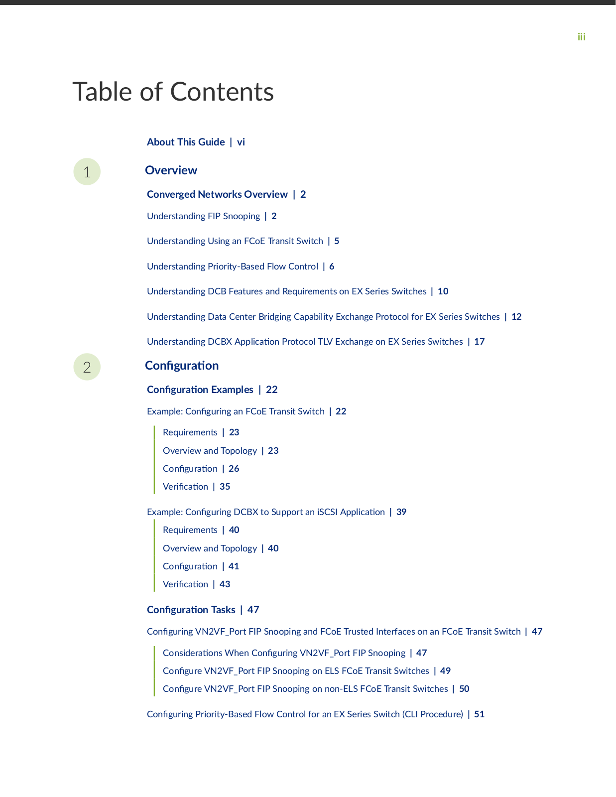
Table of Contents

1

2

About This Guide | vi

Overview

Converged Networks Overview | 2

Understanding FIP Snooping | 2

Understanding Using an FCoE Transit Switch | 5

Understanding Priority-Based Flow Control | 6

Understanding DCB Features and Requirements on EX Series Switches | 10

Understanding Data Center Bridging Capability Exchange Protocol for EX Series Switches | 12

Understanding DCBX

c

n Protocol TLV Exchange on EX Series Switches | 17

C n

r


n


C n

r


n Examples | 22


Example: C

n

r n

an FCoE Transit Switch | 22


Requirements | 23


Overview and Topology | 23


C n

r

n | 26


r

c


n | 35


Example: C n

r n

DCBX to Support an iSCSI

c n | 39


Requirements | 40


Overview and Topology | 40


C n

r

n | 41


r

c


n | 43


C

n

r


n Tasks | 47


C

n

r n

VN2VF_Port FIP Snooping and FCoE Trusted Interfaces on an FCoE Transit Switch | 47


C ns

r

ns When C n

r n VN2VF_Port FIP Snooping | 47


C n

r

VN2VF_Port FIP Snooping on ELS FCoE Transit Switches | 49


C n

r

VN2VF_Port FIP Snooping on non-ELS FCoE Transit Switches | 50

C

n

r n

Priority-Based Flow Control for an EX Series Switch (CLI Procedure) | 51

iv

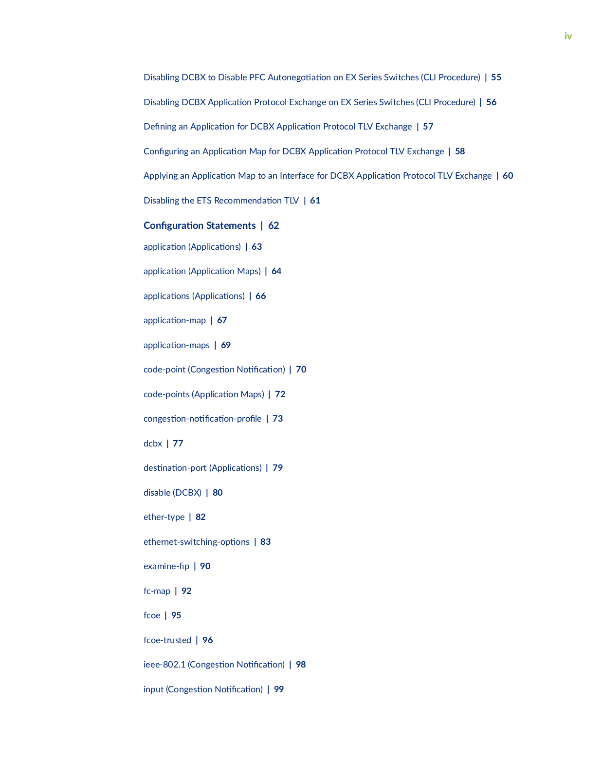
Disabling DCBX to Disable PFC

n

n on EX Series Switches (CLI Procedure) | 55

Disabling DCBX


c

n Protocol Exchange on EX Series Switches (CLI Procedure) | 56

n n

an


c

n for DCBX

c

n Protocol TLV Exchange | 57

C n

r n

an

c

n Map for DCBX

c n Protocol TLV Exchange | 58

Applying an


c

n Map to an Interface for DCBX

c n Protocol TLV Exchange | 60

Disabling the ETS R c mm n

n TLV | 61


C n

r

n Statements | 62


c

n (


c

ns)

| 63


c

n (


c

n Maps) | 64


c

ns (

c

ns)

| 66


c

n m

| 67


cn m s | 69

code-point (C

n

s

n N

c

n) | 70

code-points (


c

n Maps) | 72

c n

s

n n


c

n r


| 73

dcbx | 77


s

n

n

r

(

c

ns)

| 79

disable (DCBX) | 80


ether-type | 82


rn

sw

c

n

ns | 83

x m n

| 90


fc-map | 92


fcoe | 95


fcoe-trusted | 96


ieee-802.1 (C

n

s

n N

c

n) | 98

input (C

n s

n N

c

n) | 99

v

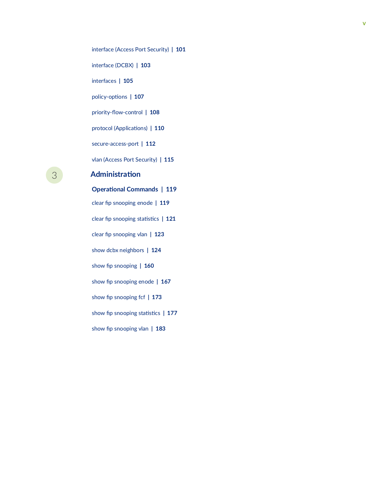
interface (Access Port Security) | 101 interface (DCBX) | 103

interfaces

| 105


cy

ns | 107

r

r y

w c

n r | 108

protocol (

c

ns) | 110

secure-access-port | 112

vlan (Access Port Security) | 115

3

m n s r

n

rn Commands | 119

clear

snooping enode | 119

clear

snooping s

s cs | 121

clear

snooping vlan | 123

show dcbx neighbors | 124

show

snooping | 160

show

snooping enode | 167

show

snooping fcf | 173

show

snooping s

s cs | 177

show

snooping vlan | 183

vi

About This Guide

Use this guide to c n r data center bridging (DCB) nc ns to support storage area network (SAN) r c on EX Series switches that do not use the Enhanced Layer 2 S w r (ELS) c n r n style.

Supported features include DCB c


b

s exchange (DCBX), Fibre Channel over Ethernet (FCoE)

transit nc ns FCoE n

z

n Protocol (FIP) snooping, and Priority Flow Control (PFC) for

managing lossless r

c classes.


NOTE: For c n

r n

DCB

nc

ns on QFX Series switches and EX Series switches that

support the Enhanced Layer 2 S

w r

(ELS) c n r n style, see Storage User Guide.


Juniper Converged Networks User Manual

1

PART

Overview

Converged Networks Overview | 2

2

CHAPTER 1

Converged Networks Overview

IN THIS CHAPTER


Understanding FIP Snooping |

2


Understanding Using an FCoE Transit Switch | 5


Understanding Priority-Based Flow Control | 6


Understanding DCB Features and Requirements on EX Series Switches | 10


Understanding Data Center Bridging Capability Exchange Protocol for EX Series Switches | 12


Understanding DCBX

c

n Protocol TLV Exchange on EX Series Switches | 17


Understanding FIP Snooping

IN THIS SECTION


FC Network Security |

3


FIP Snooping

nc

ns |

3


FIP Snooping Firewall Filters | 3


FIP Snooping m

m n


n | 4


T11 FIP Snooping S

c

c

n | 5


Fibre Channel over Ethernet (FCoE) n z n Protocol (FIP) snooping is a security mechanism that is designed to prevent unauthorized access and data transmission to a Fibre Channel (FC) network. It works by r n r c to permit only servers that have logged in to the FC network to access the network. You enable FIP snooping on FCoE VLANs when the switch is being used as an FCoE transit switch c nn c n FC n rs (servers) on the Ethernet network to FCoE forwarders (FCFs) at the FC storage area network (SAN) edge.

3

Through the FIP process, servers that have a converged network adapter (CNA) present an FCoE Node (ENode) that can log in to the FC network. The login process establishes a dedicated virtual link between the ENode and the FCF to emulate a point-to-point c nn c n that passes transparently through the FCoE transit switch.

The FCoE transit switch applies FIP snooping r w

rs at the edge access ports associated with the

FCoE VLANs on which you enable FIP snooping. FIP snooping provides security for virtual links by

m c

y cr n r w

rs based on n rm

n gathered (snooped) about FC devices during

FIP r ns c

ns


This topic describes:

FC Network Security

In r

n pure FC networks, the FCF is a trusted

n

y and server ENodes connect directly to the

FCF.

r an ENode gains access to the network through the fabric login (FLOGI) process, the FCF

enforces zoning c n

r

ns ensures that the ENode uses valid addresses, monitors the c nn c n

and performs other security nc ns to prevent unauthorized access.

FIP snooping r w


rs emulate these security

nc

ns by r v n n unauthorized access to the

FCF through the transit switch and by ensuring the security of the virtual link between each ENode and the FCF. FIP snooping also prevents man-in-the-middle c s

FIP Snooping nc ns

When you enable FIP snooping, the FCoE transit switch monitors FIP logins, s c

ns and

v r s m n s that pass through it and gathers n rm

n about the ENode address and the address

of the FCF. The transit switch uses the n rm

n to construct r w

rs that permit access only to

logged-in ENodes. All other r c on the VLAN is denied.

For example, when an ENode on an FCoE VLAN performs a successful login, the FCoE transit switch snoops the FIP n rm n constructs a r w r that permits access for the ENode, and adds the

r on all transit switch access ports associated with the FCoE VLAN.

The r w rs allow FCoE frames to pass through the transit switch only between the server ENode FCoE port and the FCF FCoE port to which the server ENode has logged in. This ensures that ENodes can only connect to the FCFs they have successfully logged in to and that only valid FCoE r c is

r nsm FIP snooping maintains the rs by tracking FCoE sessions.

FIP Snooping Firewall Filters

The FIP snooping r w rs deny any FCoE r c on the VLAN except for r c r n n from ENodes that have already logged in to the FCF.

4

FIP snooping performs these c ns and checks to ensure that FCoE r c is valid:

• Denies ENodes that use the FCF media access control (MAC) address as the source address.

Denies all r c from the ENode other than r c addressed to the FCF that the Enode has logged


into.


Restricts the ENode to sending only FCoE protocol r

c on the virtual link.

• Allows the ENode to transmit only FIP and FCoE frames to the FCF address.

Ensures that the FCoE source address an ENode uses

r fabic login and fabric discovery (FDISC) is


the address the FCF assigned to that ENode.


Ensures that the FCoE source address the FCF assigns or accepts is only used for FCoE r c

Ensures that FCoE frames are only addressed to the cc

n FCF.

FIP Snooping m m n

n


You enable FIP snooping on a per-VLAN basis. The FCoE transit switch snoops FIP frames at the access ports associated with the FIP snooping-enabled VLANs, then installs the r s n r w rs on the access ports to ensure that all snooping occurs on the FCoE transit switch network edge.

FCoE VLANs can include both access ports and trunk ports. Access ports face the hosts (FCoE servers and other FCoE n rs) and trunk ports face the FCF. When FIP snooping is enabled, the FCoE transit switch inspects both FIP frames and FCoE frames.

The FIP snooping m m n n includes these c ns r ns

Server ENode-Facing Interfaces

We recommend that you enable FIP snooping on all FCoE access ports to ensure secure c

nn c ns to

FCFs.

r you enable FIP snooping on an FCoE VLAN, the transit switch denies FCoE r

c from any

server on that VLAN n the server performs a valid fabric login with an FCF.


FCF-Facing Interfaces

You must c n

r the interface that you are using to connect to an FCF as FCoE trusted interface, and

it must be a 10 Gigabit Ethernet interface.

An FCoE trusted interface receives FCoE r c only from an FCF. The following c n

ns apply to

FCFs and FCF-facing interfaces:


• By default, FCFs are trusted n s


5

• The FCoE transit switch always processes FCF frames because they come from a trusted source.

FCoE Mapped Address r x

When you enable FIP snooping on a VLAN, n y you can specify the FCoE Mapped Address r x (FC-MAP) value for that VLAN if the network uses the fabric-provided MAC address (FPMA) addressing scheme. The FC-MAP value is a 24-bit value that n s the FCF. The FCF combines the FC-MAP value with a unique 24-bit Fibre Channel ID (FCID) value for the server during the fabric login process,

cr n

a unique 48-bit n r The FCF assigns the 48-bit value to the server ENode as its MAC

address and unique

n r for the session. Each server session the ENode establishes with the FCF

receives a unique FCID, so a server can host m

virtual links to an FCF, each with a unique 48-bit

address

n r


The FIP snooping

r compares the c n r

FC-MAP value with the FC-MAP value in the header of

frames coming from the server. If the values do not match, the FCoE transit switch denies access.

T11 FIP Snooping S c c

n


For more details about FIP snooping, see the Technical C

mm

T11 r

n z

n document

Increasing FCoE Robustness using FIP Snooping at

www 11

r

11

b c

bb 5 0 2 4v3 .


RELATED DOCUMENTATION

Understanding Using an FCoE Transit Switch | 5

Example: C

n r n an FCoE Transit Switch | 22

C n r n

VN2VF_Port FIP Snooping and FCoE Trusted Interfaces on an FCoE Transit Switch

Understanding Using an FCoE Transit Switch

You can use an EX4500 switch as a Fibre Channel over Ethernet (FCoE) transit switch. An FCoE transit switch is a Layer 2 data center bridging (DCB) switch that can transport FCoE frames and implement FCoE n z n Protocol (FIP) snooping. The switch can transport both FCoE and Ethernet LAN r c over the same network infrastructure while preserving the class of service (CoS) that Fibre Channel (FC)

rc requires.

An FCoE transit switch does not encapsulate or decapsulate FC frames in Ethernet. It is an access switch that transports FC frames that have already been encapsulated in Ethernet between FCoE n rs such as servers and an FCoE forwarder (FCF), which is in an FC storage area network (SAN). The transit

6

switch acts as a passthrough switch and is transparent to the FCF, which detects each c nn c

n to an

FCoE server as a direct point-to-point link.


When the switch acts as a transit switch, the VLANs you c n

r

for FCoE r

c can use any of the

switch ingress and egress ports, because the r

c in both

r c

ns is Ethernet

r c FCoE r

c

must use a VLAN dedicated only to FCoE r

c that does not carry any other r

c


When the switch acts as a transit switch, you must enable priority-based

w control (PFC, IEEE

standard 802.1Qbb) as a link-level w control mechanism. See Understanding Priority-Based Flow

Control for

n n rm

n FIP snooping adds security by

r n

access so that only r

c from

servers that have successfully logged in to the FC network passes through the transit switch and reaches the FC network.

The transit switch transparently connects FCoE-capable servers in an Ethernet LAN to an FCF, which has both FCoE and FC interfaces and processes both the FCoE and FC protocol stacks. The transit switch acts as a transparent access layer between FCoE servers and the FCF.

Encapsulated FCoE server

r c

ws through the transit switch to the FCoE ports on the FCF. The FCF

removes the Ethernet nc

s

n from the FCoE frames to restore the n v FC frames. N v FC

rc travels out FCF FC ports to storage devices in the FC SAN.

N v FC r c from storage devices

ws to the FCF FC ports, and the FCF encapsulates that r c

in Ethernet as FCoE r c The FCoE

r

c ws through the transit switch to the appropriate server,

and the server decapsulates the r

c


RELATED DOCUMENTATION

Understanding FIP Snooping | 2

Understanding Priority-Based Flow Control

IN THIS SECTION

Reliability of Packet Delivery in Standard Ethernet Networks and in Layer 2 Networks | 7

C c

ns for B

r Requirements When Using PFC PAUSE | 7

How PFC and C n

s n N c n r s Work With or Without DCBX | 8

7

Priority-based

w control (PFC), IEEE standard 802.1Qbb, is a link-level w control mechanism. The

w control mechanism is similar to that used by IEEE 802.3x Ethernet PAUSE, but it operates on

individual r r

s Instead of pausing all r c on a link, PFC allows you to s c v y pause r c

according to its class. This topic describes:

Reliability of Packet Delivery in Standard Ethernet Networks and in Layer 2 Networks

Standard Ethernet does not guarantee that a packet injected into the network will arrive at its intended

s

n

n Reliability is provided by upper-layer protocols. Generally, a network path consists of

m


hops between the source and

s

n

n A problem arises when r nsm

rs send packets

faster than receivers can accept them. When receivers run out of available b

r space to hold incoming

ws they silently drop

n incoming packets. This problem is generally resolved by upper-layer

protocols that detect the drops and request retransmission.


c

ns that require reliability in Layer 2 must have

w control that includes feedback from a

receiver to a sender regarding b

r availability. Using IEEE 802.3x Ethernet PAUSE control frames, a

receiver can generate a MAC control frame and send a PAUSE request to a sender when a s c

threshold of receiver b

r has been

to prevent b

r

v r

w Upon receiving a PAUSE request,

the sender stops transmission of any new packets n the receiver n

s the sender that it has

s

c

n b

r space to accept them again. The disadvantage of using Ethernet PAUSE is that it

operates on the n r link, which might be carrying m

r

c

ws Some

r

c ws do not

need

w control in Layer 2, because they are carrying

c ns that rely on upper-layer protocols

for reliability. PFC enables you to c

n

r

Layer 2 w control s

c

v y for the

r c that requires it,

such as Fibre Channel over Ethernet (FCoE)

r

c without m

c

n

other r

c on the link. You can

also enable PFC for other

r c types, such as iSCSI.


C

c


ns for B

r Requirements When Using PFC PAUSE


The receive b r must be large enough to accommodate all data that is received while the system is responding to a PFC PAUSE frame.

When you calculate b r requirements, consider the following factors:

Processing and queuing delay of the PFC PAUSE—In general, the m to detect the lack of s c n


b r space and to transmit the PFC PAUSE is negligible. However, delays can occur if the switch


detects a r

c n in b r space just as the r nsm r is beginning to transmit a maximum length


frame.


r

n delay across the media—The delay amount depends on the length and speed of the


physical link.

Response

m to the PFC PAUSE frame

8

• r

n delay across the media on the return path


NOTE: We recommend that you c n

r at least 20 percent of the b

r size for the queue

that is using PFC and that you do not specify the exact

n


Because it is mandatory to explicitly c n

r a certain percentage of b


r size for PFC, you

must also explicity c n r some b

r size for any other forwarding classes that you are

planning to use (including the default forwarding classes and the s r

n

forwarding

classes). The percentage that you allocate depends on the usage of the r s

c v classes.


How PFC and C n s n c n r s Work With or Without DCBX

PFC can be applied to an interface regardless of whether the Data Center Bridging Capability Exchange protocol (DCBX) is enabled (DCBX is enabled by default for 10-Gigabit Ethernet interfaces on EX4500 CEE-enabled switches).

However, m c control and v r s m n of PFC requires DCBX:

• When DCBX is enabled—DCBX detects the data center bridging (DCB) neighbor’s PFC c n r n

uses

n


n to

v r

s local and peer PFC c n

r n and then enables or disables PFC

depending on whether the c n

r ns are c m

b

or not. When PFC is enabled, it uses the

c n s

n n

c

n

r

which you have c n

r

and applied to the interface.

• When DCBX is not enabled—Class of service (CoS) triggers PFC when the incoming frame has a User


Priority (UP)


that matches the three-bit

rn s

c

for the c

n

s

n n

c

n

r

To manually control the use of PFC on the interface regardless of the c n

r


n of the peer data

center devices, you can explicitly change the c

n

r n of DCBX on the interface to disable PFC


n


n See "Disabling DCBX to Disable PFC

n


n on EX Series Switches (CLI

Procedure)" on page 55. When PFC

n


n is disabled, PFC is triggered by the c

n

s

n

n

c

n

r

for PFC regardless of the c

n

r n of the DCB peer.


NOTE: PFC

nc

ns

c v

y only when the peer devices connected to the local interface are


also using PFC and are c

n

r

c m

b y with the local interface. PFC must be symmetrical


—if PFC is not c

n r

to use the same

r

c class (code point) on both the local and the peer


interface, it does not have any impact on the r

c


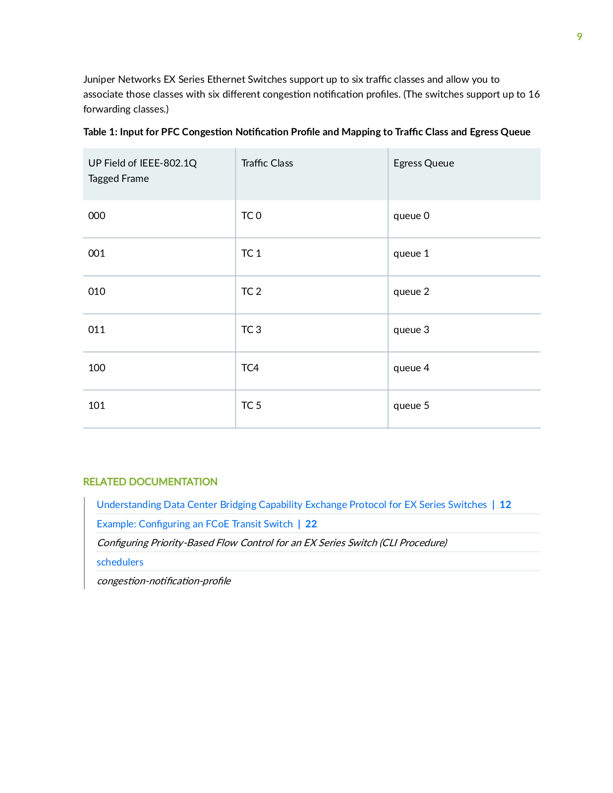
Table 1 on page 9 shows the one-to-one mapping between the UP

of an IEEE 802.1Q tagged

frame, the

r

c class, and the egress queue. In

n to s

n

a PFC c

n

s

n n

c

n

r

on an ingress port, you must set a forwarding class to match the priority s

c


in the PFC c n

s n

n

c

n

r

and to forward the frame to the appropriate queue.


9

Juniper Networks EX Series Ethernet Switches support up to six

r

c classes and allow you to

associate those classes with six

r n

c

n s

n n

c n

r

s (The switches support up to 16

forwarding classes.)


Table 1: Input for PFC C n s n

c

n

r

and Mapping to r c Class and Egress Queue


UP Field of IEEE-802.1Q

r

c Class


Egress Queue

Tagged Frame


000

TC 0


queue 0


001

TC 1


queue 1


010

TC 2


queue 2


011

TC 3


queue 3


100

TC4


queue 4


101

TC 5


queue 5


RELATED DOCUMENTATION

Understanding Data Center Bridging Capability Exchange Protocol for EX Series Switches | 12

Example: C

n

r n

an FCoE Transit Switch | 22


C n

r n

Priority-Based Flow Control for an EX Series Switch (CLI Procedure)


schedulers


c n s

n n

c

n r

10

Understanding DCB Features and Requirements on EX Series Switches

IN THIS SECTION

EX Series Switch DCB Features Overview | 10

Physical Interfaces | 11

DCBX | 11

Lossless Transport | 11

Data center bridging (DCB) is a set of enhancements to the IEEE 802.1 bridge s c c

ns DCB

ms and extends Ethernet behavior to support I/O convergence in the data center. I/O convergence

includes but is not limited to the transport of Ethernet LAN r c and Fibre Channel (FC) storage area

network (SAN) r

c on the same physical Ethernet network infrastructure.

A converged architecture saves cost by reducing the number of networks and switches required to

support both types of r

c reducing the number of interfaces required, reducing cable complexity, and

reducing m n s r

n

c v s

You can use DCB features on CEE-enabled switches to transport converged Ethernet and FC r c while providing the class-of-service (CoS) c r c r s cs and other c r c r s cs FC requires for r nsm n storage r c

NOTE: This topic only applies to DCB features on EX Series switches that do not support the Enhanced Layer 2 S w r (ELS) c n r n style. EX4500 and EX4550 switches are the only non-ELS EX Series switches that support DCB features.

DCB features on ELS EX Series switches and QFX Series switches are described in

Understanding DCB Features and Requirements.

This topic describes:

EX Series Switch DCB Features Overview

To accommodate FC r c DCB s

c

c

ns provide:


High-bandwidth interface


A discovery and exchange protocol for c mm n c n c n r n and c b

s among


neighbors to ensure consistent c

n

r

n across the network, called Data Center Bridging

11

Capability Exchange protocol (DCBX), which is an extension of Link Layer Discovery Protocol (LLDP, described in IEEE 802.1AB).

• A w control mechanism called priority-based

w control (PFC, described in IEEE 802.1Qbb) to

help provide lossless transport.


NOTE: The switches support the DCBX standards and PFC, but do not support enhanced

transmission s c n (ETS) and q n z c n

s n n

c

n (QCN).


Physical Interfaces

The switches provide the high-bandwidth interfaces (10-Gigabit Ethernet interfaces) required to support DCB and converged r c Your switch can have both 1-gigabit and 10-gigabit interfaces, depending on the c n r n DCBX works only on 10-gigabit, full-duplex interfaces. However, LLDP and DCBX are enabled by default on all the interfaces.

DCBX

DCB devices use DCBX to exchange c n r

n n

rm

n with directly connected peers (switches

and data center devices such as servers). DCBX is an extension of LLDP. If you

m to enable DCBX

on an interface on which LLDP is disabled, the c

n

r

n commit fails. See "Understanding Data

Center Bridging Capability Exchange Protocol for EX Series Switches" on page 12 for details.

Lossless Transport

FC r c requires lossless transport ( n as no frames dropped because of c n s n) Standard Ethernet does not support lossless transport, but the DCB extensions to Ethernet along with proper

b

r management enable an Ethernet network to provide the level of CoS necessary to transport FC

frames encapsulated in Ethernet over an Ethernet network.

This s c n describes these factors in cr

n lossless transport over Ethernet:

PFC

PFC is a link-level

w control mechanism similar to Ethernet PAUSE (described in IEEE 802.3x).


Ethernet PAUSE stops all r

c on a link for a s c

period of

m

PFC allows you to assign special

priority to a s

c

c r

c class for a s c

period of m without stopping the

r

c assigned to

other

r r

s on the link. You assign this priority by using a c n

s

n n

c

n

r


The switches support up to six r c classes and allow you to associate those classes with six

r n

c n s

n n

c

n

r

s


12

PFC enables you to provide lossless transport for r c assigned to use the PFC c n s n n

c

n

r

and to use standard Ethernet transport for the rest of the link r c


Br Management

B

r management is cr c to the proper nc n n

of PFC, because if b

rs are allowed to

v r w frames are dropped and transport is not lossless.


For each lossless

w priority, the switch requires s

c n b

r space to:


Store frames sent during the m it takes to send the PFC PAUSE across the cable between devices

• Store frames that are already on the wire when the sender receives the PFC PAUSE

The amount of b

r space needed to prevent frame loss due to c n s n depends on the cable

length, cable speed, and processing speed.


The switch

m

c y sets the threshold for sending a PFC PAUSE frame to accommodate delay from

cables as long as 984 feet (300 meters) and to accommodate large frames that might be on the wire when the switch sends the PAUSE. This ensures that the switch sends PAUSEframes early enough to allow the sender to stop r nsm n before the receive b rs on the switch v r w

RELATED DOCUMENTATION

Understanding Data Center Bridging Capability Exchange Protocol for EX Series Switches | 12

Example: C n r n an FCoE Transit Switch | 22

Understanding Data Center Bridging Capability Exchange Protocol for EX Series Switches

IN THIS SECTION

Basic DCBX nc n n | 13

DCBX and PFC | 14

DCBX and FCoE | 14

DCBX and iSCSI | 14

How DCBX Is Implemented on the Switches | 15

13

Features That Are Not Fully Supported by DCBX on EX Series Switches | 16

Data Center Bridging Capability Exchange protocol (DCBX) is a discovery and exchange protocol for c mm n c n c n r n and c b s among neighbors to ensure consistent c n r n across the data center bridging network. It is an extension of Link Layer Discovery Protocol (LLDP). If

you m to enable DCBX on an interface on which LLDP is disabled, the c n r n commit fails. Data center bridging devices use DCBX to exchange c n r n n rm n with directly connected peers (devices such as switches and servers in a data center bridging network).

NOTE: This topic applies only to DCBX on EX Series switches that do not support the Enhanced Layer 2 S w r (ELS) c n r n style. EX4500 and EX4550 switches are the only non-ELS EX Series switches that support DCBX.

DCBX support on ELS EX Series switches and QFX Series switches is described in Understanding DCBX.

You can use DCBX to:

Discover the data center bridging c b

s of peers

Detect data center bridging feature m sc n

r

n or mismatches between peers

m c y enable or disable priority-based

w control (PFC) on an interface depending on

whether the PFC c n r n of the local interface is the same as the PFC c n r n of the DCB peer

This topic describes:

Basic DCBX

nc n n


DCBX features support PFC, the Fibre Channel over Ethernet (FCoE)

c n and other Layer 2 or

Layer 4

c

ns (such as iSCSI). DCBX is enabled or disabled on a per-interface basis. The default

n


n behavior is: DCBX is enabled if the peer device connected to the interface also supports

DCBX.


If the peer device connected to the interface does not support DCBX, DCBX remains enabled on the switch, but the switch detects that DCBX is not enabled on the peer and reports a m sc n r n for that interface when you issue the show dcbx neighbors command.

During n

n of c b

s the switch pushes the PFC c n r n to an

c

peer if the

peer is c n

r as willing to learn the PFC c n r n from other peers. The switch does not

14

support autoprovisioning and does not change its own c n r n during

n

n to match

the peer c n r n

is, the switch is not willing to learn the PFC c n

r

n from peers.

DCBX and PFC

r you enable PFC on a switch interface, DCBX uses

n


n to control the

r

n

state

of PFC

nc

n

y


DCB devices must use the same r

c class (code point) on both the local and peer device. If the peer

device connected to the interface supports PFC and is provisioned for the same

r

c class as the


switch interface, DCBX sets the PFC

r n state to enabled. If the peer device connected to the

interface does not support PFC or is not provisioned for the same r

c class, DCBX sets the


r

n

state to disabled.


If the peer

v r

s s that it is willing to learn its PFC c

n

r

n from the switch, DCBX pushes the

switch’s PFC c n

r n to the peer and does not check the peer’s

m n s r

v

state.


You can manually override DCBX control of the PFC

r

n

state on a per-interface basis by


disabling

n

n If you disable

n

n on an interface on which you have c

n

r

PFC, then PFC remains enabled on that interface regardless of the peer c n r


n To disable PFC on

an interface, delete any PFC c n

r

n on the interface.


DCBX and FCoE

DCBX is mandatory for running FCoE

c

ns because FCoE r

c requires PFC to ensure lossless

transport and PFC is a component of DCBX.


The FCoE

c

n is c n r

by default on DCBX interfaces. Because of the FCoE requirement for

lossless transport, we recommend that you c n


r the interfaces that carry FCoE

r c for PFC. See

C n

r n Priority-Based Flow Control for an EX Series Switch (CLI Procedure).


DCBX

v r

s m n of the FCoE

c

n

nc

ns as follows:


• If you c n

r

the fcoe forwarding class and PFC c n s

n n

c n r

and assign these

components to the interfaces that carry FCoE

r c DCBX

v r

s s their FCoE capability and

assigned 802.1p code points to the DCB peer, and DCBX reports the FCoE capability and assigned 802.1p code points of the DCB peer to the switch.

DCBX and iSCSI

DCBX is not

ss n

for iSCSI

c

ns These

c

ns provide a method for linking data

storage c

s over IP networks. Unlike Fibre Channel (FC) c

mm

n c

ns which require special-

purpose cabling, iSCSI can be run over long distances by using

x s

n network infrastructure.

15

You might want to use iSCSI over DCB to reduce latency in a network that is oversubscribed. You might also want to use it to provide predictable and certain c n responsiveness, m n n Ethernet’s dependence on TCP/IP for the retransmission of dropped Ethernet frames.

DCBX v r s s switch interfaces that are c n

r to support the iSCSI

c

n their PFC

capability, and their assigned 802.1p code points.


How DCBX Is Implemented on the Switches

On the switches, the m m n n of DCBX is:

Supported on aggregated Ethernet interfaces composed of 10-Gigabit Ethernet interfaces

Enabled by default on all 10-Gigabit Ethernet interfaces

On the switches, DCBX supports the

c

n type-length-value (TLV) — thus, DCBX interfaces on

the switch can exchange n

rm n with their DCB peers about

c n capability, PFC capability,

and 802.1p code-point s

n s This m

m n

n includes the following:

• The FCoE

c n is enabled by default on DCBX interfaces on the switch. Therefore, you do not

c n r an

c n map for the default FCoE

c n


The switches do not have a default FCoE forwarding class—therefore, you must explicitly c n r a forwarding class with the name fcoe and associate that class with the interfaces carrying FCoE

rc If PFC is enabled, the 802.1p code points are assigned, and the interfaces are associated with


a forwarding class, the switch n

s FCoE

c n capability on the DCBX interface.

Do not explicitly c n

r an FCoE

c n map, because that generates a commit error.

You can c n r

n Layer 2 or Layer 4

c ns to be supported by the DCBX

c

n TLV feature. To do this, explicitly c

n

r an

c n map and associate the


c

n map with one of the DCBX interfaces. DCBX then

v r s s the

c n c b

s

of the associated interface and checks the c

b

s of the connected peer device.


• If the peer device connected to the local interface does not support PFC or the peer’s PFC

c n r n is not the same as the local interface’s PFC c n r n DCBX m c y disables PFC for the local interface.

NOTE: You can manually override DCBX control of the PFC

r n state on a per-

interface basis. See "Disabling DCBX to Disable PFC

n

n on EX Series Switches

(CLI Procedure)" on page 55.


16

Features That Are Not Fully Supported by DCBX on EX Series Switches

The m m n

n of DCBX on EX Series switches does not fully support the following features:


• Enhanced transmission s

c

n (ETS) (IEEE 802.1Qaz)—ETS is a bandwidth management


mechanism to support dynamic

c n of bandwidth for DCBX r

c classes.


EX Series switches do not support using ETS to dynamically allocate bandwidth to s c

r c


classes. Instead, the switches handle all DCBX r

c as a single default r

c class, group 7.

However, the switches do support the ETS R c mm n

n TLV. The ETS R c mm n

n TLV


communicates the ETS s

n s that the switch wants the connected DCBX peer interface to use.

If the peer interface is willing, it changes its c n

r

n to match the c n

r n in the ETS


R c

mm n

n TLV sent by the switch (group 7).


The switch also

v r

s s that it is not willing to change its ETS s

n s


The

v r

s m n

of ETS TLV is enabled by default for DCBX interfaces. If you want, you can


disable this

v r

s m

n

See Disabling the ETS R c mm n

n TLV.


• A default FCoE forwarding class—The switch does not have a default FCoE forwarding class with default mapping to a priority queue for FCoE r c

NOTE: Because the switches do not support a default FCoE forwarding class, you must explicitly c n r a forwarding class and name it fcoe.

RELATED DOCUMENTATION

Understanding DCB Features and Requirements on EX Series Switches | 10

Understanding Using an FCoE Transit Switch | 5

Example: C n r n an FCoE Transit Switch | 22

17

Understanding DCBX

c n Protocol TLV Exchange on EX Series

Switches


IN THIS SECTION


Basic Steps for S

n Up

c

n Protocol TLV Exchange | 17


c

ns | 18


c

n Maps | 19


c | 19


Classifying and r

r z n

c

n r

c n Protocol n rm n | 20


Requirements for Interfaces in Non-FCoE

c ns to Exchange


Data Center Bridging Capability Exchange protocol (DCBX) discovers the data center bridging (DCB)

c b

s of connected peers. DCBX also v r s s the c

b

s of

c

ns on interfaces by

exchanging

c

n protocol n rm

n through

c

n type, length, and value (TLV) elements.

DCBX is an extension of Link Layer Discovery Protocol (LLDP). LLDP must remain enabled on every interface on which you want to use DCBX.

LLDP and DCBX are enabled by default on all 10-Gigabit Ethernet interfaces of EX4500 CEE-enabled switches.

NOTE: This topic applies only to DCBX on EX Series switches that do not support the Enhanced Layer 2 S w r (ELS) c n r n style. EX4500 and EX4550 switches are the only non-ELS EX Series switches that support DCBX.

DCBX TLV exchange on ELS EX Series switches and QFX Series switches is described in

Understanding DCBX c n Protocol TLV Exchange.

This topic describes:

Basic Steps for S n Up

c n Protocol TLV Exchange

S

n up


c n protocol exchange for FCoE

c ns consists of:

C

n

r n

the fcoe forwarding class for IEEE 802.1p code point 011

C

n

r n

PFC for IEEE 802.1p code point 011


18

We recommend that you use code point 011 for the fcoe forwarding class, because this is the

c nv n

n

IEEE 802.1p code point for FCoE r

c We recommend that you c n

r PFC to use the

same code point. See "Example: C

n

r n an FCoE Transit Switch" on page 22.


S

n

up

c

n protocol exchange for non-FCoE

c ns consists of:


n n

c


ns


Mapping the


c ns to IEEE 802.1p code points


C n

r n c

ss

rs to r r

z

incoming r

c map and map the incoming r

c to the


c

n by the

r

c code points


Applying the


c

n maps and c ss rs to interfaces


Except for FCoE


c

ns you must explicitly

n

and map all

c ns that you want an

interface to

v r

s


NOTE: Do not explicitly c n

r

an FCoE

c n map, because doing that generates a


commit error.


cns

Before an interface can exchange

c

n protocol n

rm

n you must


n the

c

ns that

you want to

v r

s

except for the FCoE


c

n which is


n by default. You can


n

Layer 2

c

ns by EtherType


Layer 4

c ns (such as iSCSI

c

ns) by a c

mb n

n of protocol (TCP or UDP) and


s n

n port


The EtherType is a two-octet


in the Ethernet frame that denotes the protocol encapsulated in the

frame. For a list of common EtherTypes, see

s

n r

s

r

v

r


r y

x

on the IEEE standards

r n z

n website. For a list of port numbers and protocols, see the Service

Name and Transport Protocol Port Number Registry at

www

n r

ss

nm n s s rv c

n m s


r n mb rs s rv c

n m s

r

n mb rs xm on the Internet Assigned Numbers Authority (IANA)

website.


The switch

m

c

y

n s the FCoE


c n as EtherType 0x8906.


19

cn Maps

An

c n map maps

n

c ns to one or more IEEE 802.1p code points. Each

c n

map contains one or more


c ns DCBX includes the c n r

c n code points in the

protocol TLVs exchanged with the connected peer.


To exchange protocol TLVs for an (with the xc n of the FCoE

c

n you must include the

c

n in an

c

n map

c

n)


Mapping an

c


n to code points does two things:


Maps incoming

r

c with the same code points to that

c

n


Allows you to c

n

r c ss rs that map incoming

c

n r

c by code point, to a


forwarding class and a loss priority to apply class of service (CoS) to

c

n r c and r r z

cn r c

You apply an

c

n map to an interface to enable DCBX

c

n protocol exchange on that

interface for each


c

n s

c

in the

c

n map.

c

ns that you want an interface

to v r

s must be c

n

r

in the

c

n map that you apply to the interface (except the FCoE

c

n) Do not explicitly c

n r

an FCoE

c

n map, because doing that generates a

commit error.


Classifying and

r

r

z n

c

n

r


c


When

r c arrives at an interface, the interface c

ss

s the incoming

r c based on its code points.

C

ss

rs map code points to loss

r r

s and forwarding classes. The loss priority

r r

z s the

r

c The forwarding class determines the r

c output queue and CoS service level.


When you map an


c

n to an IEEE 802.1p code point in an

c

n map and apply the


c

n map to an interface, incoming

r c on the interface that matches the

c

n code

points is mapped to the appropriate

c

n The


c

n receives the loss priority and the CoS

associated with the forwarding class for those code points, and its r


c is placed in the output queue

associated with the forwarding class.


You can use the default c

ss r or you can c n


r

a c

ss r to map the

c

n code points


n

in the

c

n map to forwarding classes and loss

r r

s


r c for the FCoE

c

n is c

ss

and

r

r

z

by your c

n

r

n of the fcoe forwarding

class.


20

Requirements for Interfaces in Non-FCoE

c

ns to Exchange

c

n

Protocol n

rm

n


For non-FCoE

c

ns interfaces on which you want to exchange

c n protocol TLVs must

include the following two items:


The


c

n map that contains the

c


n


A c

ss

r


See

n n

an

c

n for DCBX

c

n Protocol TLV Exchange and C n

r n

an


c n Map for DCBX

c n Protocol TLV Exchange.


RELATED DOCUMENTATION

Understanding Data Center Bridging Capability Exchange Protocol for EX Series Switches | 12

Understanding DCB Features and Requirements on EX Series Switches | 10

Understanding Priority-Based Flow Control

Disabling DCBX

c n Protocol Exchange on EX Series Switches (CLI Procedure) | 56

2

PART

n r n

C n

r

n Examples | 22

C

n

r

n Tasks | 47

C

n

r

n Statements | 62


22

CHAPTER 2


C n r

n Examples

IN THIS CHAPTER

Example: C n r n an FCoE Transit Switch | 22

Example: C n r n DCBX to Support an iSCSI

c n | 39

Example: C n r n an FCoE Transit Switch

IN THIS SECTION

Requirements | 23

Overview and Topology | 23

C n

r

n | 26

r

c

n | 35

You can use an EX4500 CEE-enabled switch as a Fibre Channel over Ethernet (FCoE) transit switch,

enabling it to transport both FCoE and Ethernet LAN

r

c Using the same switch to support both your

storage network and r

n IP-based data c

mm

n c

ns reduces the costs of powering, cooling,

provisioning, maintaining, and managing your network.


This example includes:


• FIP snooping for security


• Priority-based w control (PFC) for lossless transport


• The FCoE forwarding class for the DCBX

c

n protocol type, length, value (TLV) exchange

• A trusted port c nn c n to the FCoE forwarder (FCF)

• Enlarged maximum transmission unit (MTU) size for handling FCoE r c

23

This example shows how to c n r an FCoE transit switch:

Requirements

This example uses the following hardware and s w r components:

One EX4500 switch (CEE-capable model)

Junos OS Release 12.1 or later for EX Series switches

One FCoE Node (ENode)

One FCoE forwarder (FCF)

Before you begin, be sure you have:

• C n r the VLAN fcoe-vlan on the switch. See C n r n VLANs for EX Series Switches.

Overview and Topology

IN THIS SECTION

Topology | 25

FCoE transmissions are vulnerable to address s

n

and man-in-the-middle

c s

because they are

not actually sent through point-to-point links. This example describes how to c n

r

the switch so

that it provides security similar to that provided by

r

n Fibre Channel (FC) networks. The switch

is transparent to the ENode and the FCF, so the ENode and FCF communicate just as they would for a point-to-point link.

FIP snooping is disabled by default. You enable FIP snooping on a per-VLAN basis for VLANs that carry FCoE r c Ensure that a VLAN that carries FCoE r c carries only FCoE r c because enabling FIP snooping denies access for all other Ethernet r c

This example shows how to c n r FIP snooping on a VLAN of the EX4500 switch that is connected with one ENode, that is, a server equipped with converged network adapters (CNAs). The setup for this example includes the VLAN fcoe-vlan on the switch.

This example also shows how to c

n r PFC on the interfaces that are being used for FCoE

r c and

how to c n

r an FCoE trusted port to handle r

c between the switch and the FCF gateway to the

storage area network (SAN).


You must c n

r PFC r r

s for the interfaces that are carrying FCoE r c because

w control

must be implemented on the link level for this type of

r c


24

NOTE: Data Center Bridging Capability Exchange protocol (DCBX) is enabled by default on all

10-Gigabit Ethernet interfaces on EX4500 switches. DCBX

m

c y controls whether PFC

is enabled or disabled on the interface. However, you must c n

r

the PFC r r s

s

c n

the r c class and queue. See C n r n Priority-Based Flow Control for an EX

Series Switch (CLI Procedure).


You c

n

r trunk interfaces that connect to the FCF as trusted interfaces. The switch must use the

same FCoE MAC Address r x (FC-MAP) value that is being used by the FCF. Therefore, if the FCF is using a nondefault FC-MAP value, you must c n r the FC-MAP value on the switch to match that value.

You must also enlarge the MTU size for all interfaces (both access and trunk) that are handling FCoE

rc to accommodate the maximum FC frame and Ethernet header sizes.

This example also includes c

n

r n the fcoe forwarding class to be used for the FCoE r

c so that

it can take advantage of DCBX support for the


c n Protocol TLV Exchange. See "Understanding

Data Center Bridging Capability Exchange Protocol for EX Series Switches" on page 12 for

n

n rm n


NOTE: C

n

r n and applying PFC and a forwarding class fcoe on the DCBX interfaces


m

c

y enables the DCBX FCoE

c

n protocol exchange on those interfaces. Do not

explicitly c

n r an FCoE

c n map, because doing that generates a commit error. See

"Understanding Data Center Bridging Capability Exchange Protocol for EX Series Switches" on

page 12 for

n n

rm

n


NOTE: PFC is supported only on 10-Gigabit Ethernet interfaces.

NOTE: We recommend that you also:

C

n

r

the PFC c n s

n n

c

n

r

for the same 802.1p code points that you


are using for the fcoe forwarding class. We recommend code point 011, because this is the


c

nv n


n IEEE 802.1p code point for FCoE r

c


C

n

r

at least 20 percent of the b

r for the queue that is using PFC.

Do not specify the exact

n when c

n

r n

the b

r for the queue that is using PFC.

Loading...
+ 165 hidden pages