

Page 1

Contrail Service Orchestration Monitoring
Published
2021-03-27
and Troubleshooting Guide
Release
6.0.0
Page 2

Juniper Networks, Inc.
1133 Innovation Way
Sunnyvale, California 94089
USA
408-745-2000
www.juniper.net
Juniper Networks, the Juniper Networks logo, Juniper, and Junos are registered trademarks of Juniper Networks, Inc. in
the United States and other countries. All other trademarks, service marks, registered marks, or registered service marks
are the property of their respective owners.
Juniper Networks assumes no responsibility for any inaccuracies in this document. Juniper Networks reserves the right
to change, modify, transfer, or otherwise revise this publication without notice.
Contrail Service Orchestration Monitoring and Troubleshooting Guide
6.0.0
Copyright © 2021 Juniper Networks, Inc. All rights reserved.
The information in this document is current as of the date on the title page.
ii
YEAR 2000 NOTICE
Juniper Networks hardware and software products are Year 2000 compliant. Junos OS has no known time-related
limitations through the year 2038. However, the NTP application is known to have some difficulty in the year 2036.
END USER LICENSE AGREEMENT
The Juniper Networks product that is the subject of this technical documentation consists of (or is intended for use with)
Juniper Networks software. Use of such software is subject to the terms and conditions of the End User License Agreement
(“EULA”) posted at https://support.juniper.net/support/eula/. By downloading, installing or using such software, you
agree to the terms and conditions of that EULA.
Page 3

Table of Contents
1
About the Documentation | v
Documentation and Release Notes | v
Documentation Conventions | v
Documentation Feedback | viii
Requesting Technical Support | viii
Self-Help Online Tools and Resources | ix
Creating a Service Request with JTAC | ix
Troubleshooting Contrail Service Orchestration Issues
Identifying Connectivity Issues for Cloud-based Deployments | 2
iii
Identifying Connectivity Issues by Using Ping | 2
Identifying Connectivity Issues by Using Traceroute | 6
Troubleshooting Site Activation Issues for Cloud-based Deployments | 9
Troubleshooting Site Activation Issues | 9
Prerequisites to Activate a Site | 9
Site activation process is stuck in device detected state | 10
Site activation process is stuck in bootstrap state | 10
Site activation process failed in bootstrap state | 10
Site activation process failed during provisioning | 10
Troubleshooting Image, License, and Policy Deployment Issues for Cloud-based
Deployments | 12
Troubleshooting Image, License, and Policy Deployment Issues | 12
Unable to find device image version | 12
Upgrade device image using J-Web | 13
Unable to connect to the device | 13
Device image version is different from the recommended version | 14
Policy deployment failed | 14
No data for next-generation firewall site | 14
No data for SD-WAN site | 15
Page 4

Traffic from Spoke Sites Are Dropped or Are Not Reaching Internet or Destination | 15
SLA Violation-Original Link Recovered After SLA Violation | 16
All WAN links are Up But Not All Links Are Utilized | 16
Troubleshooting SMTP Issues for Cloud-based Deployments | 17
Troubleshooting SMTP Issues | 17
Basic Configuration for SMTP Server | 17
Troubleshooting Site, Device and Link Issues | 20
Troubleshooting Site, Device, and Link Issues | 20
Secure OAM Activation Failure | 20
Configure SD-WAN Site Failure | 21
Device Activation Failure | 21
Dual-CPE Activation Failure for NFX Series Devices | 22
iv
Dual-CPE Activation Failure for SRX Series Devices | 22
Link Switch Event or Performance Metrics is Not Displayed | 23
WAN Link Performance Parameters are Not Displayed | 23
LTE Interface Issues | 24
Page 5

About the Documentation
IN THIS SECTION
Documentation and Release Notes | v
Documentation Conventions | v
Documentation Feedback | viii
Requesting Technical Support | viii
Use this guide to monitor CSO infrastructure services and microservices and troubleshoot CSO installation,
login, site activation, license, and deployment-related issues.
v
Documentation and Release Notes
To obtain the most current version of all Juniper Networks®technical documentation, see the product
documentation page on the Juniper Networks website at https://www.juniper.net/documentation/.
If the information in the latest release notes differs from the information in the documentation, follow the
product Release Notes.
Juniper Networks Books publishes books by Juniper Networks engineers and subject matter experts.
These books go beyond the technical documentation to explore the nuances of network architecture,
deployment, and administration. The current list can be viewed at https://www.juniper.net/books.
Documentation Conventions
Table 1 on page vi defines notice icons used in this guide.
Page 6
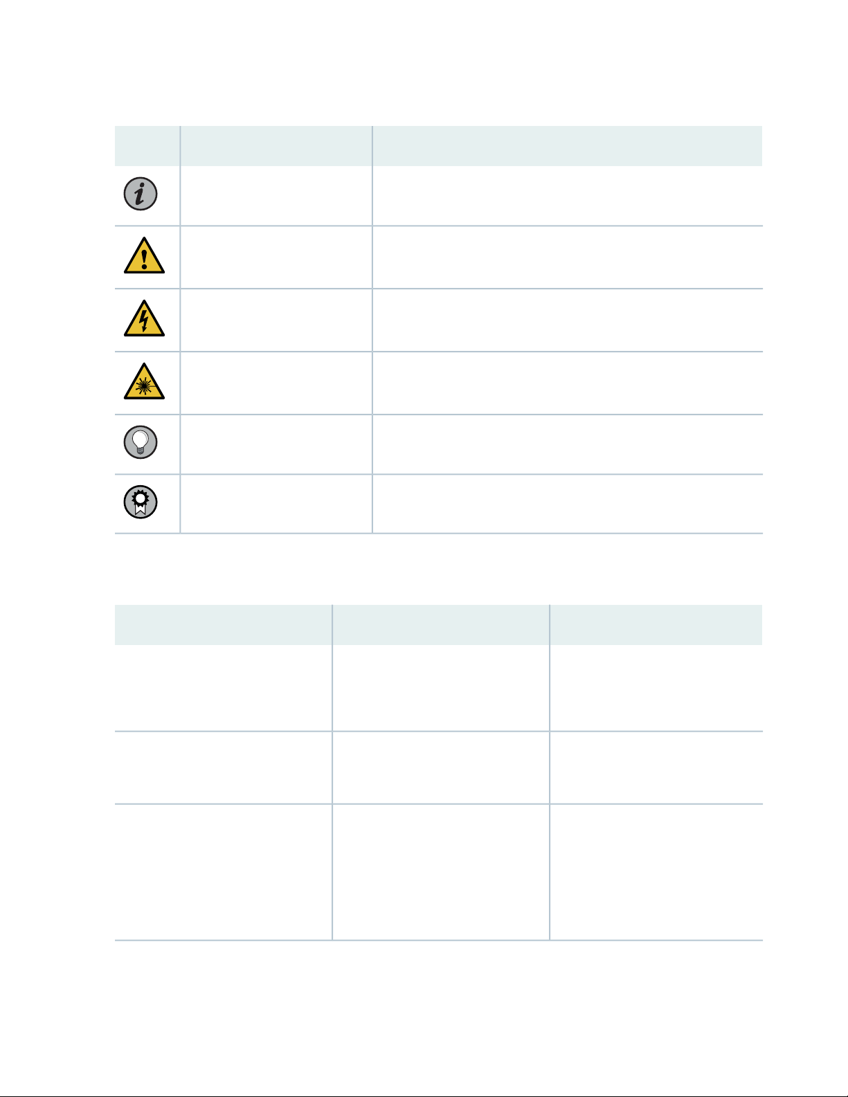
Table 1: Notice Icons
vi
DescriptionMeaningIcon
Indicates important features or instructions.Informational note
Caution
Indicates a situation that might result in loss of data or hardware
damage.
Alerts you to the risk of personal injury or death.Warning
Alerts you to the risk of personal injury from a laser.Laser warning
Indicates helpful information.Tip
Alerts you to a recommended use or implementation.Best practice
Table 2 on page vi defines the text and syntax conventions used in this guide.
Table 2: Text and Syntax Conventions
ExamplesDescriptionConvention
Fixed-width text like this
Italic text like this
Represents text that you type.Bold text like this
Represents output that appears on
the terminal screen.
Introduces or emphasizes important
•
new terms.
Identifies guide names.
•
Identifies RFC and Internet draft
•
titles.
To enter configuration mode, type
the configure command:
user@host> configure
user@host> show chassis alarms
No alarms currently active
A policy term is a named structure
•
that defines match conditions and
actions.
Junos OS CLI User Guide
•
RFC 1997, BGP Communities
•
Attribute
Page 7

Table 2: Text and Syntax Conventions (continued)
vii
ExamplesDescriptionConvention
Italic text like this
Text like this
< > (angle brackets)
| (pipe symbol)
Represents variables (options for
which you substitute a value) in
commands or configuration
statements.
Represents names of configuration
statements, commands, files, and
directories; configuration hierarchy
levels; or labels on routing platform
components.
variables.
Indicates a choice between the
mutually exclusive keywords or
variables on either side of the symbol.
The set of choices is often enclosed
in parentheses for clarity.
Configure the machine’s domain
name:
[edit]
root@# set system domain-name
domain-name
To configure a stub area, include
•
the stub statement at the [edit
protocols ospf area area-id]
hierarchy level.
The console port is labeled
•
CONSOLE.
stub <default-metric metric>;Encloses optional keywords or
broadcast | multicast
(string1 | string2 | string3)
# (pound sign)
[ ] (square brackets)
Indention and braces ( { } )
; (semicolon)
GUI Conventions
Indicates a comment specified on the
same line as the configuration
statement to which it applies.
Encloses a variable for which you can
substitute one or more values.
Identifies a level in the configuration
hierarchy.
Identifies a leaf statement at a
configuration hierarchy level.
rsvp { # Required for dynamic MPLS
only
community name members [
community-ids ]
[edit]
routing-options {
static {
route default {
nexthop address;
retain;
}
}
}
Page 8

Table 2: Text and Syntax Conventions (continued)
viii
ExamplesDescriptionConvention
Bold text like this
> (bold right angle bracket)
Represents graphical user interface
(GUI) items you click or select.
Separates levels in a hierarchy of
menu selections.
In the Logical Interfaces box, select
•
All Interfaces.
To cancel the configuration, click
•
Cancel.
In the configuration editor hierarchy,
select Protocols>Ospf.
Documentation Feedback
We encourage you to provide feedback so that we can improve our documentation. You can use either
of the following methods:
Online feedback system—Click TechLibrary Feedback, on the lower right of any page on the Juniper
•
Networks TechLibrary site, and do one of the following:
Click the thumbs-up icon if the information on the page was helpful to you.
•
Click the thumbs-down icon if the information on the page was not helpful to you or if you have
•
suggestions for improvement, and use the pop-up form to provide feedback.
E-mail—Send your comments to techpubs-comments@juniper.net. Include the document or topic name,
•
URL or page number, and software version (if applicable).
Requesting Technical Support
Technical product support is available through the Juniper Networks Technical Assistance Center (JTAC).
If you are a customer with an active Juniper Care or Partner Support Services support contract, or are
Page 9

covered under warranty, and need post-sales technical support, you can access our tools and resources
online or open a case with JTAC.
JTAC policies—For a complete understanding of our JTAC procedures and policies, review the JTAC User
•
Guide located at https://www.juniper.net/us/en/local/pdf/resource-guides/7100059-en.pdf.
Product warranties—For product warranty information, visit https://www.juniper.net/support/warranty/.
•
JTAC hours of operation—The JTAC centers have resources available 24 hours a day, 7 days a week,
•
365 days a year.
Self-Help Online Tools and Resources
For quick and easy problem resolution, Juniper Networks has designed an online self-service portal called
the Customer Support Center (CSC) that provides you with the following features:
Find CSC offerings: https://www.juniper.net/customers/support/
•
Search for known bugs: https://prsearch.juniper.net/
•
ix
Find product documentation: https://www.juniper.net/documentation/
•
Find solutions and answer questions using our Knowledge Base: https://kb.juniper.net/
•
Download the latest versions of software and review release notes:
•
https://www.juniper.net/customers/csc/software/
Search technical bulletins for relevant hardware and software notifications:
•
https://kb.juniper.net/InfoCenter/
Join and participate in the Juniper Networks Community Forum:
•
https://www.juniper.net/company/communities/
Create a service request online: https://myjuniper.juniper.net
•
To verify service entitlement by product serial number, use our Serial Number Entitlement (SNE) Tool:
https://entitlementsearch.juniper.net/entitlementsearch/
Creating a Service Request with JTAC
You can create a service request with JTAC on the Web or by telephone.
Visit https://myjuniper.juniper.net.
•
Call 1-888-314-JTAC (1-888-314-5822 toll-free in the USA, Canada, and Mexico).
•
For international or direct-dial options in countries without toll-free numbers, see
https://support.juniper.net/support/requesting-support/.
Page 10

1
PART
Troubleshooting Contrail Service
Orchestration Issues
Identifying Connectivity Issues for Cloud-based Deployments | 2
Troubleshooting Site Activation Issues for Cloud-based Deployments | 9
Troubleshooting Image, License, and Policy Deployment Issues for Cloud-based
Deployments | 12
Troubleshooting SMTP Issues for Cloud-based Deployments | 17
Troubleshooting Site, Device and Link Issues | 20
Page 11

CHAPTER 1
Identifying Connectivity Issues for Cloud-based Deployments
IN THIS CHAPTER
Identifying Connectivity Issues by Using Ping | 2
Identifying Connectivity Issues by Using Traceroute | 6
2
Identifying Connectivity Issues by Using Ping
You can use Contrail Service Orchestration (CSO) to perform a ping operation from a device (provider hub,
tenant device, CPE device, enterprise hubs, or next-generation firewall device) to a remote host for
identifying issues in connectivity with the remote host.
When you ping a remote host from a device, an Internet Control Message Protocol (ICMP) packet is sent
to the remote host. By analyzing the results of the ping operation, you can identify the possible device
connectivity issues between the remote host and the device.
NOTE: In Contrail Service Orchestration (CSO) Release 5.0, the following devices support ping:
NFX Series: NFX150, NFX250
•
SRX Series: SRX300, SRX320, SRX340, SRX345, SRX1500, SRX4100, SRX4200, SRX4600
•
vSRX
•
Page 12

To perform the ping operation:
1. Do one of the following:
To initiate a ping from a provider hub device, select Resources > Provider Hub Devices.
•
The :Provider Hub Devices page appears.
To initiate a ping from a tenant device, select Resources > Tenant Devices.
•
The Tenant Devices page appears.
2. Select a device from the list of devices displayed and click More > Ping.
The Ping page appears.
NOTE: You can initiate a ping from a device only when its operational status (in CSO) is Up.
3. Complete the configuration according to the guidelines provided in Table 3 on page 3.
3
NOTE: Fields marked with an asterisk (*) are mandatory.
4. Click Ping to initiate the ping request.
A job is created and a Ping Progress page appears. After the host sends the ping packets, the Ping
Result page appears. If the ping operation is successful, the Ping Result page displays the parameters
specified in Table 4 on page 5.
If the ping operation fails, the Ping Result page displays an appropriate error message (such as No
response or No route to host), indicating that there is an issue in the connectivity to the remote host.
Table 3: Fields on the Ping page
DescriptionField
Enter the IPv4 address or hostname of the remote host.Remote Host
Ping Request Packets
Enter the number of ping request packets to be sent to the remote host.
Default: 5.
Advanced
Range: 1 through 300.
Page 13

Table 3: Fields on the Ping page (continued)
DescriptionField
4
Source Interface
Hostname Resolution
Rapid Ping
Select the source interface on the device through which you want to send the ping
request to the remote host. If you do not select a source interface, ping requests
are sent on all interfaces.
To clear the selected interface, click Clear All and select another interface.
Click the toggle button to enable or disable (default) the display of hostname of
the hops along the path to the remote host.
Click the toggle button to enable or disable (default) sending ping requests rapidly.
If you enable this option, the device sends a minimum of 100 ping request packets
per second or sends a packet as soon as a response to the previous packet is
received, whichever is greater.
If the source device does not receive a response for 500 ms, timeout is
•
considered.
If the source device receives a response within 500 ms, the next ping request
•
packet is sent immediately.
NOTE: The ping results are displayed in a single consolidated message instead of
individual messages for each ping request packet sent.
Packet Fragmentation
Packet Size (bytes)
Wait Time (seconds)
Click the toggle button to enable or disable (default) the fragmenting of ping request
packets.
If packet fragmentation is disabled, ping packets with the maximum transmission
unit (MTU) greater than 1500 bytes are dropped.
Enter the size (in bytes) of the ping request packet.
Default: 56 bytes.
Range:
1 through 1,472 bytes, if packet fragmentation is disabled.
•
1 through 65,468 bytes, if packet fragmentation is enabled.
•
Enter the time (in seconds) for which the source device waits for a response to the
ping request packet. The source device considers the remote host as not reachable
after the wait time elapses.
Default: 10 seconds.
Range: 0 through 600 seconds.
Page 14

Table 3: Fields on the Ping page (continued)
DescriptionField
5
Incoming Interface
Routing Instance
Click the toggle button to include or exclude (default) information (on the Ping
Result page) about the interface on the source device that receives the ping
responses..
Select a specific routing instance that the ping request packets can use to reach
the remote host.
The ping result displays the information about the connectivity between the source
device and the remote host based on the selected routing instance.
To clear the selected routing instance, click Clear All and select another routing
instance.
Table 4: Fields on the Ping Result page
DescriptionField
Packet Loss
Round Trip Time Taken
(in µs)
Displays the percentage of ping packets sent for which the source device did not receive
a response.
Displays the following information about the duration (in microseconds) between the time
when the device sends the ping request and the time when the device receives a response
from the remote host.
Details
Incoming Interface
Displays the following:
Minimum: The minimum time taken to receive a response for a ping request packet.
•
Maximum: The maximum time taken to receive a response for a ping request packet.
•
Average: The average time taken to receive a response for all the ping request packets
•
sent in a ping operation.
Standard Deviation: The variation of the round trip time from the mean round trip time.
•
Sequence number of all the ping request packets.Sequence
Result of the ping request packets—Success or Failure.Result
Interface on the source device on which the responses are received for the ping requests.
This data appears if you have enabled the Incoming Interface option on the Ping page.
Time taken (in microseconds) to receive response to a ping request packet.Time Taken
Page 15

Identifying Connectivity Issues by Using Traceroute
You can use Contrail Service Orchestration (CSO) to perform a traceroute operation from a device (provider
hub, tenant device, CPE device, enterprise hubs, or next-generation firewall device) to the remote host.
Traceroute helps you view the path that a packet travels to reach the remote host. The result is useful in
identifying the point of network failure in the path between the source device and remote host.
NOTE: In Contrail Service Orchestration (CSO) Release 5.0, the following devices support
traceroute:
NFX Series: NFX150, NFX250
•
SRX Series: SRX300, SRX320, SRX340, SRX345, SRX1500, SRX4100, SRX4200, SRX4600
•
vSRX
•
To perform traceroute operation:
6
1. Do one of the following:
To initiate traceroute from a provider hub device, select Resources > Provider Hub Devices.
•
The Provider Hub Devices page appears.
To initiate traceroute from a tenant device, select Resources > Tenant Devices.
•
The Tenant Devices page appears.
2. Select a device from the list of devices displayed and click More > Traceroute.
The Traceroute page appears.
3. Complete the configuration according to the guidelines provided in Table 5 on page 7.
NOTE: Fields marked with an asterisk (*) are mandatory.
4. Click Traceroute to initiate the traceroute operation.
A job is created and a traceroute progress page appears. If the traceroute operation is successful, the
Traceroute Result page displays the traceroute parameters specified in Table 6 on page 8.
If the traceroute operation fails, the Traceroute Result page displays an appropriate error message
(such as No response or No route to host).
Page 16

Table 5: Fields on the Traceroute page
DescriptionField
Enter the IPv4 address or hostname of the remote host.Remote Host
7
Maximum Hops
Advanced
Source Interface
Hostname Resolution
Wait Time (seconds)
Specify the maximum number of network devices that a packet can pass through to
reach the remote host.
Default: 30.
Range: 1 through 255.
If the number of hops to reach the remote host exceeds the set value, the traceroute
packet is dropped.
Select a source interface on the device from which you want to send the packets to the
remote host.
Click Clear All to remove the selected interface and select another interface.
Click the toggle button to enable or disable (default) the display of hostname of the hops
in the path to the remote host.
Enter the time until which the device waits for a response from the remote host to a
packet sent before considering timeout.
Default: 10 seconds.
Range: 0 through 86,399 seconds.
Routing Instance
Select a routing instance that the traceroute request packets can use to reach the remote
host.
The trace result displays the route information based on the configured routing instance
type.
To clear the selected routing instance, click Clear All and select another routing instance.
Table 6 on page 8 lists the parameters on the Traceroute Result page when the traceroute operation is
successful.
Page 17

Table 6: Fields on the Traceroute Result page
DescriptionField
8
Hop
Time Taken by Packet 1
Time Taken by Packet 2
Time Taken by Packet 3
Hostname or IPv4 address of the network devices that the packet passed
through to reach the remote host.
Duration (in microseconds) between the time from when the source device
sends a packet, and the time it received a response from the hops and the
remote host.
Page 18

CHAPTER 2
Troubleshooting Site Activation Issues for Cloud-based Deployments
IN THIS CHAPTER
Troubleshooting Site Activation Issues | 9
Troubleshooting Site Activation Issues
9
IN THIS SECTION
Prerequisites to Activate a Site | 9
Site activation process is stuck in device detected state | 10
Site activation process is stuck in bootstrap state | 10
Site activation process failed in bootstrap state | 10
Site activation process failed during provisioning | 10
Prerequisites to Activate a Site
Problem
Description: User was unable to activate a site. Specify the prerequisites to activate a site.
Solution
The prerequisites to activate a site are as follows:
Check the spoke connectivity to Internet.
•
Check the firewall policies between the CPE device and the CSO. The hub or spoke must be able to
•
communicate to CSO through ports 443 (activation), 444 (activation for small and medium deployments),
Page 19

7804 (outbound-ssh), 3514(app-track logs), 514 (syslog), and 2216 (telemetry agent). See Deployment
Guide
Site activation process is stuck in device detected state
Problem
Description: Site activation process is stuck in device detected state; how do I proceed?
Solution
Do the following:
Verify that your device can reach the Internet.
•
Verify the date and time on the device.
•
Verify that the DHCP server and the device are connected to the ge-0/0/0 port.
•
Reboot the device.
•
10
Site activation process is stuck in bootstrap state
Problem
Description: Site activation process is stuck in bootstrap state; how do I proceed?
Solution
If the site activation proces is stuck for more than 15 minutes, then do the following:
Verify that your network firewall allows UDP ports 500 and 4500 for the SD-WAN site.
•
Verify that your network firewall allows TCP port 7804 for the next-generation firewall site.
•
Reboot the device.
•
Site activation process failed in bootstrap state
Problem
Description: Site activation process failed in bootstrap state; how do I proceed?
Solution
Verify that the device is zeroized or running the factory-default configuration. If the device is pre-staged,
then ensure that the configuration is not overlapping with the CSO stage-1 configuration. Reboot the
device.
Site activation process failed during provisioning
Problem
Page 20

Description: Site activation process failed during provisioning; how do I proceed?
Solution
Verify the device connectivity to the Internet. Retry the failed job in CSO. Navigate to Monitor > Jobs,
select the failed job, and click Retry Job.
11
Page 21

CHAPTER 3
Troubleshooting Image, License, and Policy Deployment Issues for Cloud-based Deployments
IN THIS CHAPTER
Troubleshooting Image, License, and Policy Deployment Issues | 12
Troubleshooting Image, License, and Policy Deployment Issues
12
IN THIS SECTION
Unable to find device image version | 12
Upgrade device image using J-Web | 13
Unable to connect to the device | 13
Device image version is different from the recommended version | 14
Policy deployment failed | 14
No data for next-generation firewall site | 14
No data for SD-WAN site | 15
Traffic from Spoke Sites Are Dropped or Are Not Reaching Internet or Destination | 15
SLA Violation-Original Link Recovered After SLA Violation | 16
All WAN links are Up But Not All Links Are Utilized | 16
Unable to find device image version
Problem
Description: How do I find my device image version without console access to the device?
Solution
Use the J-Web interface to find the device image version.
Page 22

To access the J-Web interface of the device:
1. Connect your laptop or workstation to any port (except ge-0/0/0) that is available on the device.
2. Enable DHCP on the laptop or workstation and acquire the IP address and gateway information from
the device.
3. Use the gateway address (also known as the device address) in the Web browser to connect to the
J-Web interface.
4. Log in with the default username root. As the root user, you don’t need a password to log in.
The Welcome page appears displaying the device image version.
Upgrade device image using J-Web
Problem
Description: Device image version is 15.1X49-D110; how do I upgrade the device image before site
onboarding?
13
Solution
Use the J-Web interface to upgrade the device image.
To upgrade the device image using J-Web:
1. Download the recommended image or the software version from the Juniper Networks website to
your local machine.
2. Log in to the J-Web interface.
3. Select Maintain > Software > Upload Package.
4. Navigate to the device image file location and select the file.
5. Click Upload and Install Package to upgrade the device image.
Unable to connect to the device
Problem
Description: I am not able to log in to the device through the J-Web interface or through the device console.
How do I proceed?
Solution
Page 23

Press and hold the Reset Config button on the device for 15 seconds. Wait for two minutes for the device
to restore the factory-default settings. Log in to the device as the root user (no password is required for
the root user). If you are still not able to access the device, then reboot the device.
Device image version is different from the recommended version
Problem
Description: The device image version at the site is 15.1X49D110, but the recommended image version
is 15.1X49D170.x. Should I upgrade the device image manually before site onboarding?
Solution
You don't’ need to upgrade the device image manually before site onboarding. You can do either of the
following:
Upgrade the device image during site activation in CSO—While you are in the site configuration or
•
onboarding workflow, select the device image from the drop-down list.
14
NOTE: Device image upgrade during site activation delays the site activation process.
Upgrade the device image post site activation in CSO—Navigate to Resources > Images, select the image,
•
and click Deploy.
Policy deployment failed
Problem
Description: Policy deployment failed; how do I proceed?
Solution
Verify the device connectivity to the Internet. Retry the policy deployment.
No data for next-generation firewall site
Problem
Description: Application Visibility Monitoring page shows no data for the next-generation firewall site;
how do I proceed?
Solution
Do the following:
Verify that your network firewall allows the UDP port 514.
•
Verify the application visibility monitoring page after multiple application sessions (in the time range of
•
3–5 minutes) traffic.
Page 24

Use an appropriate time interval for the query. For example, if you are querying for the traffic sent in
•
the last 10 minutes, then try using a 15-minute query (minimum time interval).
No data for SD-WAN site
Problem
Description: Application visibility and WAN performance data on the Site Management page shows no
data for the SD-WAN site; how do I proceed?
Solution
Do the following:
Verify the application visibility and WAN performance data after multiple application sessions (in the
•
time range of 3-5 minutes) traffic.
Use an appropriate time interval for the query. For example, if you are querying for the traffic sent in
•
the last 10 minutes, then try using a 15-minute query (minimum time interval).
15
Traffic from Spoke Sites Are Dropped or Are Not Reaching Internet or Destination
Problem
Description: Traffic from spoke sites are dropped or are not reaching the Internet or their specified
destinations.
Solution
1. Verify the alerts for overlay or underlay connections, and check whether BGP is active.
Log in to Administration portal, and select Monitor > Alerts and Alarm > Alerts.
2. Check whether the firewall policies are successfully deployed to the CPE device and that the traffic or
applications are matching the policies to permit the traffic to Internet or to other sites.
In Administration Portal, select Sites > Site-Name > Policies.
Or log in to the CPE device and verify that the next-generation firewall policies are deployed.
3. Check the routes in the default VRF route table in the CPE device.
4. Trace the route and verify the reachability from the hub to the destination. If the hub cannot reach the
Internet, then verify whether the firewall and NAT policies are set up properly in the hub.
5. For further troubleshooting, collect the logs and output results and contact Juniper Networks Technical
Support team.
Page 25

SLA Violation-Original Link Recovered After SLA Violation
Problem
Description: The original link is recovered after a service-level agreement (SLA) violation but the application
traffic does not switch back to the original link.
Solution
Applications change links only on an SLA violation, because applications are not tied to a specific link and
are based on SLA type, such as path preference or link performance metrics.
All WAN links are Up But Not All Links Are Utilized
Problem
Description: All WAN links are up but not all links are being utilized.
Solution
It is possible that all SD-WAN policies can select the same WAN link if they match the SLAs. If the CPE
receives a lot of matching and non-matching application traffic for SD-WAN policies, but not all WAN
links are being used, then ensure the following:
16
1. Check that the CPE device receives multiple flows per application.
2. Check that all the WAN overlays are up (IPsec, GRE) in the CPE device and the hub device.
3. Check the SLA performance data or real-time performance monitoring (RPM) probe results in the CPE
device for all links.
Log in to the Administration Portal, and select Monitor > Applications > SLA Performance.
Page 26

CHAPTER 4
Troubleshooting SMTP Issues for Cloud-based Deployments
IN THIS CHAPTER
Troubleshooting SMTP Issues | 17
Troubleshooting SMTP Issues
17
IN THIS SECTION
Basic Configuration for SMTP Server | 17
Basic Configuration for SMTP Server
Problem
Description: User was unable to configure the SMTP e-mail server.
Solution
1. Check the SMTP server settings.
SMTP server address—Check the host name or network address of the SMTP e-mail server. Typical
•
SMTP server addresses or host names are as follows:
smtp.juniper.net
•
smtp.gmail.com
•
smtp.mail.yahoo.com
•
•
AWS
Page 27

TLS—Check whether Transport Layer Security (TLS) option is enabled. This setting ensures that the
•
information is transmitted over an encrypted channel. Not all SMTP servers support encryption. If
TLS option is enabled for an SMTP server that does not support TLS, then disable the TLS option.
Port—Check with your e-mail service provider for the port number that the SMTP server listens to.
•
Generally, port number 587 is used for a TLS connection and port number 25 is used for unencrypted
connections.
Typical SMTP server settings are as follows:
smtp.juniper.net—Set TLS to No and port number to 25
•
smtp.gmail.com—Set TLS to Yes and port number to 587
•
smtp.mail.yahoo.com—Set TLS to Yes and port number to 465 or 587
•
2. Check the SMTP authentication settings.
Check whether the e-mail server requires authentication. If yes, then specify the following options.
•
From Name
•
18
User Name
•
Password
•
From E-mail Address
•
NOTE: If Gmail blocks SMTP e-mails, then log in to Gmail account, navigate to Advanced
Settings > Security > Less secure app access and click the toggle button to turn on Allow
less secure apps option.
3. Test SMTP settings by sending a test e-mail.
If you are unable to send a test e-mail:
a. Check the SMTP server settings to see if they match the SMTP server provider’s settings.
b. Check authentication credentials.
c. Check the SMTP server provider’s security settings for SMTP (for example: Gmail blocks SMTP
email unless user selects less secure app settings on their gmail account).
d. Check whether there is network access from CSO to the SMTP server.
e. Check whether the firewall is blocking SMTP traffic to SMTP server or whether the ports are blocked.
If the server settings and authentication settings are correct, check whether the firewall is blocking
Page 28

port 587 and 465 and SMTP traffic. If it is a case of the firewall blocking, then work with the network
administrator to unblock ports 465, 587, and SMTP traffic.
RELATED DOCUMENTATION
Configuring SMTP Settings
19
Page 29

CHAPTER 5
Troubleshooting Site, Device and Link Issues
IN THIS CHAPTER
Troubleshooting Site, Device, and Link Issues | 20
Troubleshooting Site, Device, and Link Issues
20
IN THIS SECTION
Secure OAM Activation Failure | 20
Configure SD-WAN Site Failure | 21
Device Activation Failure | 21
Dual-CPE Activation Failure for NFX Series Devices | 22
Dual-CPE Activation Failure for SRX Series Devices | 22
Link Switch Event or Performance Metrics is Not Displayed | 23
WAN Link Performance Parameters are Not Displayed | 23
LTE Interface Issues | 24
Secure OAM Activation Failure
Problem
Description: After entering the activation code , the CPE device status remains in DEVICE_DETECTED
state; the csp.tssm_bootstrap-<site-name> job fails or the job status remains in In Progress state for a long
time.
Solution
Check whether CSO is reachable or not by executing the following command on the CPE device.
user@host > ping <cso-ip > source < management-ip-configured-on-loopback-interface >
Page 30

If the ping fails, then check whether the secure OAM tunnels are up by using the following command.
user@host > show security ipsec inactive-tunnels
If the secure OAM tunnels are not up, verify the connectivity to the OAM hub.
Configure SD-WAN Site Failure
Problem
Description: The configure site operation fails for a spoke site.
Solution
1. Log in to Customer Portal and select Sites > Site Management.
The site status must be Configured. If the site status is Configuration Failed, then the “tssm configure
sites” job must have failed.
2. Click Monitor > Jobs and check the job details to verify which task has failed.
If the ship device task has failed, then CSO has failed to push the required secure OAM tunnel
configuration to the hub device.
21
3. Check the connectivity between CSO and the hub.
4. If there are any other failures, then go to Sites > Site Management >Site-Name> Configure Site and
review the input provided for configuring the site.
Device Activation Failure
Problem
Description: After entering the activation code , the device status remains is DEVICE_DETECTED state
for a long time.
Solution
After entering the activation code, the activation window must display the progress of device activation
and must indicate that device has been successfully detected. If the device status remains in
DEVICE_DETECTED state, then follow the steps listed below:
1. Log in to Customer Portal and select Resources-> Devices.
The Devices page appears.
2. Check the Management Status of the device.
If the management status is DEVICE_DETECTED, then the deployment of the stage-1 configuration
on device has failed or device has failed to send the BOOTSTRAP COMPLETE notification to CSO.
3. Login into the device and verify whether the stage-1 configuration is committed on the device.
Page 31

4. Verify the connectivity between CSO and the device loop back address.
5. Navigate to Monitor > Jobs page and verify the status of csp.tssm_bootstrap-<site name > job.
If the job is in successful state, then ztp job will be triggered.
•
If the job is in in-progress state, then the CPE device failed to establish the connection over the
•
secure OAM tunnel.
6. If device failed to establish the connection within an hour, or if the csp.tssm_bootstrap-<site name >”
job fails, then check the bootstrap task details.
7. Once the connectivity issue is resolved, navigate to Resources > Devices and activate the device.
The csp.tssm_ztp-<site name > job must be successful state. If the job failed, check the task details
verify which task has failed.
Dual-CPE Activation Failure for NFX Series Devices
22
Problem
Description: ZTP Job failed for dual CPE NFX Series devices.
Solution
For a site with dual CPE NFX Series devices, two ZTP jobs, namely, csp.tssm_ztp-<site-name> _cpe0 and
csp.tssm_ztp-<site-name>_cpe1 are created. One ZTP job is created per each node.
While the jobs are still in progress and after the Gateway Router (GWR) is spawned successfully, two more
jobs, namely, form_device_cluster are created per each node for cluster formation.
Log in to Administration Portal and select Monitor > Jobs to view the form_device_cluster job. If cluster
formation fails, the form_device_cluster job and the csp.tssm_ztp-<site-name> _cpe0,
csp.tssm_ztp-<site-name>_cpe1 jobs are reported as failure.
For any cluster formation job failure, check the logs from the device at /tmp/cluster_gwr.log.
For further troubleshooting, collect the logs and output results and contact Juniper Networks SRE team.
Dual-CPE Activation Failure for SRX Series Devices
Problem
Description: ZTP Job failed for dual SRX Series devices
Solution
For a site with dual CPE SRX Series devices, two ZTP jobs, namely , csp.tssm_ztp-<site-name> _cpe0 and
, csp.tssm_ztp-<site-name>_cpe1 are created. One ZTP job is created per each node.
Page 32

In case of dual SRX Series devices, as a pre-requisite, the chassis cluster is already formed manually before
starting the device activation. The csp.tssm_ztp-<site-name>_cpe1 job will report success quickly, and the
actual ztp progress can be tracked through the csp.tssm_ztp-<site-name>_cpe0 job. In case of any failure,
refer to ZTP job task details.
Link Switch Event or Performance Metrics is Not Displayed
Problem
Description: Link switch event is not displayed in the UI
Solution
Check whether the device is able to reach southbound load balancer VM (SBLB VM) and the time is
synchronized with the NTP server.
root@gwr.spoke-nfx> show system uptime
Current time: 2019-03-04 15:37:46 IST
Time Source: NTP CLOCK
System booted: 2019-02-28 15:13:49 IST (4d 00:23 ago)
Protocols started: 2019-02-28 15:13:50 IST (4d 00:23 ago)
Last configured: 2019-03-04 14:58:58 IST (00:38:48 ago) by csp
3:37PM up 4 days, 24 mins, 1 user, load averages: 0.42, 0.30, 0.26
23
Even when the link switch is successful on the device, it may not be indicated in the UI because of the
missing syslog events. Link switch event in UI is indicated based on the APPQOE_BEST_PATH_SELECTED”
syslog with reason as sla violated that is received from CPE device.
Log in to Customer Portal and select Monitor > Device Events to view all the syslogs that are received
from the CPE device To filter the APPQOE_BEST_PATH_SELECTED events, use the following query:
Event Name = APPQOE_BEST_PATH_SELECTED and Reason = sla violated.
WAN Link Performance Parameters are Not Displayed
Problem
Description: WAN link performance parameters, such as latency, packet loss, E2E delay, jitter, and
throughput are not displayed in the UI.
Solution
Check whether the device is able to reach southbound load balancer VM (SBLB VM) and the time is
synchronized with the NTP server.
root@gwr.spoke-nfx> show system uptime
Current time: 2019-03-04 15:37:46 IST
Page 33

Time Source: NTP CLOCK
System booted: 2019-02-28 15:13:49 IST (4d 00:23 ago)
Protocols started: 2019-02-28 15:13:50 IST (4d 00:23 ago)
Last configured: 2019-03-04 14:58:58 IST (00:38:48 ago) by csp
3:37PM up 4 days, 24 mins, 1 user, load averages: 0.42, 0.30, 0.26
Login to Customer Portal and select Sites > Site Management > Site-Name > WAN tab to view the WAN
link performance.
The WAN link performance details for latency, packet loss, E2E delay, and jitter are retreived from
•
APPQOE_ACTIVE_SLA_METRIC_REPORT syslog. To filter the APPQOE_ACTIVE_SLA_METRIC_REPORT
events, use the following query:
Event Name = APPQOE_ACTIVE_SLA_METRIC_REPORT and Site = <site-name >.
The WAN link performance details for throughput is retrieved from
•
APPTRACK_ACTIVE_SLA_METRIC_REPORT syslog. To filter the
APPTRACK_ACTIVE_SLA_METRIC_REPORT events, use the following query:
24
Event Name = APPTRACK_SESSION_CLOSE and Site = <site-name>.
LTE Interface Issues
Problem
Description: LTE interface is not receiving the IP address.
Solution
Check the data validity of the SIM using the mobile device.
•
Check the LTE module connection status to ensure that there is adequate mobile signal strength.
•
user@host>show modem wireless network cl-1/1/0
LTE Connection details
Connected time: 2880
IP: 192.12.219.210
Gateway: 192.12.219.209
DNS: 192.123.123.123
IPv6: ::
Gatewayv6: ::
DNSv6: ::
Input bps: 0
Output bps: 0
Bytes Received: 1952
Bytes Transferred: 2164
Page 34

Packets Received: 10
Packets Transferred: 20
Wireless Modem Network Info
Current Modem Status: Connected
Current Service Status: Normal
Current Service Type: PS
Current Service Mode: LTE
Current Band: B3
...
Check the Current Modem Status, Current Service Status, Current Service Type, and Current Service
Mode fields.
For NFX150 device, ensure that the external antenna is connected properly.
•
25
 Loading...