

Page 1

Cisco ISE and Juniper EX Switches for
Published
2021-02-03
802.1X-Based Authentication
Page 2

Juniper Networks, Inc.
1133 Innovation Way
Sunnyvale, California 94089
USA
408-745-2000
www.juniper.net
Juniper Networks, the Juniper Networks logo, Juniper, and Junos are registered trademarks of Juniper Networks, Inc. in
the United States and other countries. All other trademarks, service marks, registered marks, or registered service marks
are the property of their respective owners.
Juniper Networks assumes no responsibility for any inaccuracies in this document. Juniper Networks reserves the right
to change, modify, transfer, or otherwise revise this publication without notice.
Cisco ISE and Juniper EX Switches for 802.1X-Based Authentication
Copyright © 2021 Juniper Networks, Inc. All rights reserved.
The information in this document is current as of the date on the title page.
ii
YEAR 2000 NOTICE
Juniper Networks hardware and software products are Year 2000 compliant. Junos OS has no known time-related
limitations through the year 2038. However, the NTP application is known to have some difficulty in the year 2036.
END USER LICENSE AGREEMENT
The Juniper Networks product that is the subject of this technical documentation consists of (or is intended for use with)
Juniper Networks software. Use of such software is subject to the terms and conditions of the End User License Agreement
(“EULA”) posted at https://support.juniper.net/support/eula/. By downloading, installing or using such software, you
agree to the terms and conditions of that EULA.
Page 3

Table of Contents
1
About the Documentation | iv
Documentation and Release Notes | iv
Documentation Conventions | iv
Documentation Feedback | vii
Requesting Technical Support | vii
Self-Help Online Tools and Resources | viii
Creating a Service Request with JTAC | viii
How to Configure Cisco ISE and Juniper EX Switches for 802.1X-Based
Authentication
Configure Cisco ISE and Juniper EX Switches for 802.1X-Based Authentication | 10
iii
About This Network Configuration Example | 10
Overview | 10
Topology | 11
Step-by-Step Procedure | 12
Import the Juniper Wired Device Profile | 12
Add EX Switches to the Juniper Device Profile | 13
Create Authorization Profiles | 14
Create Endpoint Identity Groups | 18
Add Endpoints | 19
Create User Identity Groups | 20
Add Users | 21
Set Authentication Policies | 25
Set Authorization Policies | 27
Configure a Cisco ISE Policy to Enable Guest Access | 29
Configure a Colorless Port Using IETF Egress-VLAN-ID Attributes | 34
Configure the 802.1X Protocol on the EX Switch | 41
Configure Windows 10 | 42
Testing and Validation | 47
Verify IP Phone Authentication Status | 48
Verify Connections to Windows 10 Clients | 50
Page 4
About the Documentation
IN THIS SECTION
Documentation and Release Notes | iv
Documentation Conventions | iv
Documentation Feedback | vii
Requesting Technical Support | vii
This Network Configuration Example (NCE) shows you how to configure Cisco Identity Services Engine
2.X (Cisco ISE) and Juniper EX switches for IEEE 802.1X-based authentication. Cisco ISE allows you to
import network device profiles in XML format, enabling integration with any IEEE 802.1X standard network
device. This example shows you how to import the Juniper network device profile.
iv
Documentation and Release Notes
To obtain the most current version of all Juniper Networks®technical documentation, see the product
documentation page on the Juniper Networks website at https://www.juniper.net/documentation/.
If the information in the latest release notes differs from the information in the documentation, follow the
product Release Notes.
Juniper Networks Books publishes books by Juniper Networks engineers and subject matter experts.
These books go beyond the technical documentation to explore the nuances of network architecture,
deployment, and administration. The current list can be viewed at https://www.juniper.net/books.
Documentation Conventions
Table 1 on page v defines notice icons used in this guide.
Page 5
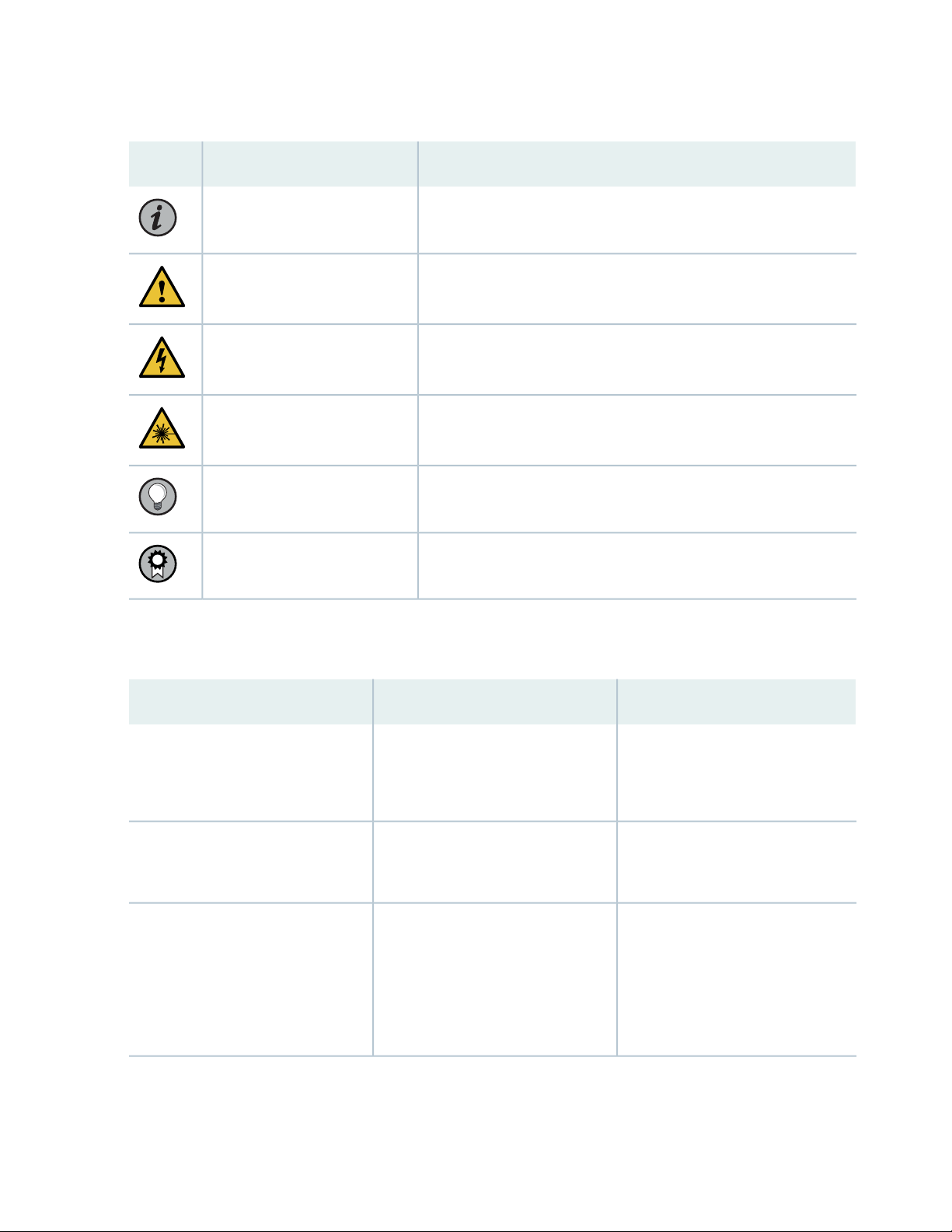
Table 1: Notice Icons
v
DescriptionMeaningIcon
Indicates important features or instructions.Informational note
Caution
Indicates a situation that might result in loss of data or hardware
damage.
Alerts you to the risk of personal injury or death.Warning
Alerts you to the risk of personal injury from a laser.Laser warning
Indicates helpful information.Tip
Alerts you to a recommended use or implementation.Best practice
Table 2 on page v defines the text and syntax conventions used in this guide.
Table 2: Text and Syntax Conventions
ExamplesDescriptionConvention
Fixed-width text like this
Italic text like this
Represents text that you type.Bold text like this
Represents output that appears on
the terminal screen.
Introduces or emphasizes important
•
new terms.
Identifies guide names.
•
Identifies RFC and Internet draft
•
titles.
To enter configuration mode, type
the configure command:
user@host> configure
user@host> show chassis alarms
No alarms currently active
A policy term is a named structure
•
that defines match conditions and
actions.
Junos OS CLI User Guide
•
RFC 1997, BGP Communities
•
Attribute
Page 6

Table 2: Text and Syntax Conventions (continued)
vi
ExamplesDescriptionConvention
Italic text like this
Text like this
< > (angle brackets)
| (pipe symbol)
Represents variables (options for
which you substitute a value) in
commands or configuration
statements.
Represents names of configuration
statements, commands, files, and
directories; configuration hierarchy
levels; or labels on routing platform
components.
variables.
Indicates a choice between the
mutually exclusive keywords or
variables on either side of the symbol.
The set of choices is often enclosed
in parentheses for clarity.
Configure the machine’s domain
name:
[edit]
root@# set system domain-name
domain-name
To configure a stub area, include
•
the stub statement at the [edit
protocols ospf area area-id]
hierarchy level.
The console port is labeled
•
CONSOLE.
stub <default-metric metric>;Encloses optional keywords or
broadcast | multicast
(string1 | string2 | string3)
# (pound sign)
[ ] (square brackets)
Indention and braces ( { } )
; (semicolon)
GUI Conventions
Indicates a comment specified on the
same line as the configuration
statement to which it applies.
Encloses a variable for which you can
substitute one or more values.
Identifies a level in the configuration
hierarchy.
Identifies a leaf statement at a
configuration hierarchy level.
rsvp { # Required for dynamic MPLS
only
community name members [
community-ids ]
[edit]
routing-options {
static {
route default {
nexthop address;
retain;
}
}
}
Page 7
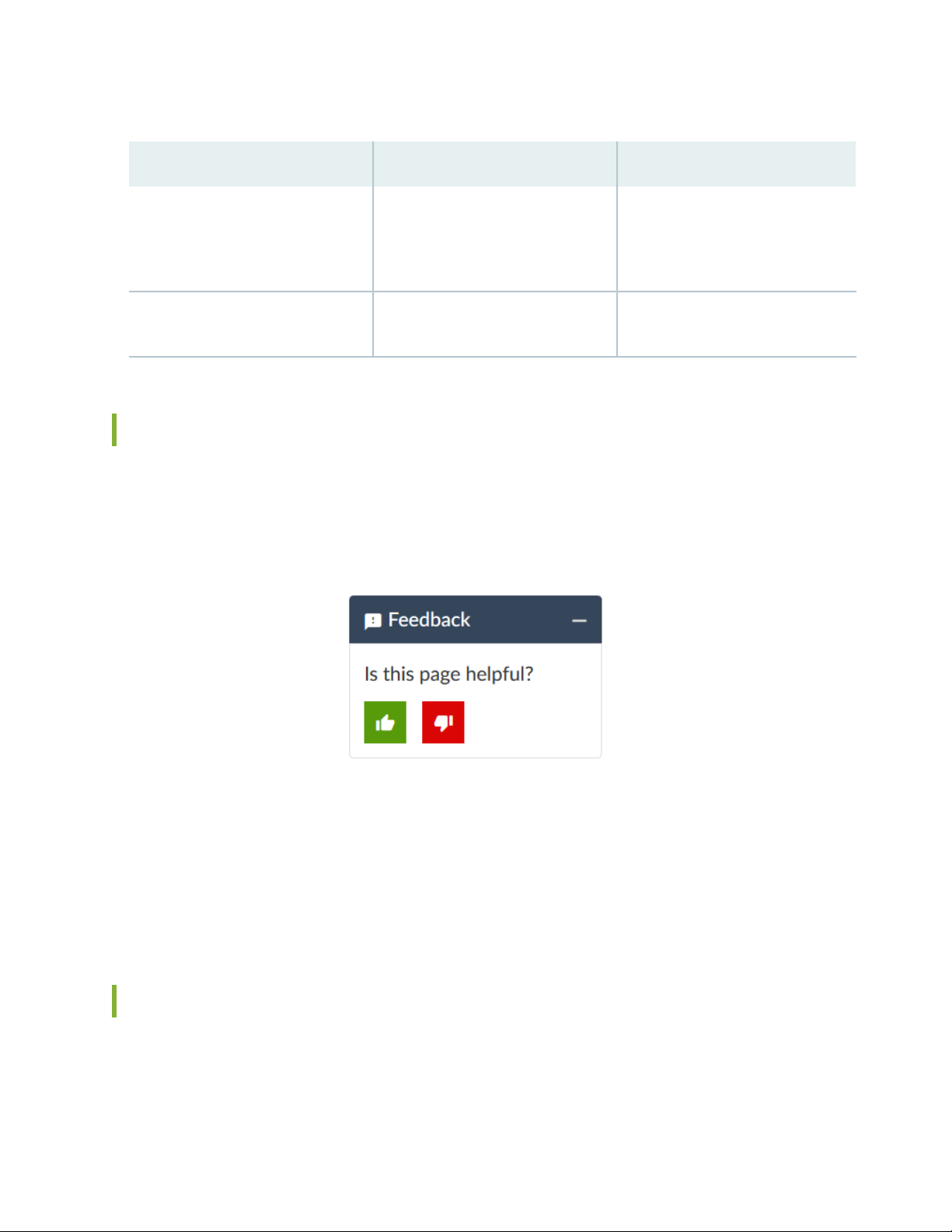
Table 2: Text and Syntax Conventions (continued)
vii
ExamplesDescriptionConvention
Bold text like this
> (bold right angle bracket)
Represents graphical user interface
(GUI) items you click or select.
Separates levels in a hierarchy of
menu selections.
In the Logical Interfaces box, select
•
All Interfaces.
To cancel the configuration, click
•
Cancel.
In the configuration editor hierarchy,
select Protocols>Ospf.
Documentation Feedback
We encourage you to provide feedback so that we can improve our documentation. You can use either
of the following methods:
Online feedback system—Click TechLibrary Feedback, on the lower right of any page on the Juniper
•
Networks TechLibrary site, and do one of the following:
Click the thumbs-up icon if the information on the page was helpful to you.
•
Click the thumbs-down icon if the information on the page was not helpful to you or if you have
•
suggestions for improvement, and use the pop-up form to provide feedback.
E-mail—Send your comments to techpubs-comments@juniper.net. Include the document or topic name,
•
URL or page number, and software version (if applicable).
Requesting Technical Support
Technical product support is available through the Juniper Networks Technical Assistance Center (JTAC).
If you are a customer with an active Juniper Care or Partner Support Services support contract, or are
Page 8

covered under warranty, and need post-sales technical support, you can access our tools and resources
online or open a case with JTAC.
JTAC policies—For a complete understanding of our JTAC procedures and policies, review the JTAC User
•
Guide located at https://www.juniper.net/us/en/local/pdf/resource-guides/7100059-en.pdf.
Product warranties—For product warranty information, visit https://www.juniper.net/support/warranty/.
•
JTAC hours of operation—The JTAC centers have resources available 24 hours a day, 7 days a week,
•
365 days a year.
Self-Help Online Tools and Resources
For quick and easy problem resolution, Juniper Networks has designed an online self-service portal called
the Customer Support Center (CSC) that provides you with the following features:
Find CSC offerings: https://www.juniper.net/customers/support/
•
Search for known bugs: https://prsearch.juniper.net/
•
viii
Find product documentation: https://www.juniper.net/documentation/
•
Find solutions and answer questions using our Knowledge Base: https://kb.juniper.net/
•
Download the latest versions of software and review release notes:
•
https://www.juniper.net/customers/csc/software/
Search technical bulletins for relevant hardware and software notifications:
•
https://kb.juniper.net/InfoCenter/
Join and participate in the Juniper Networks Community Forum:
•
https://www.juniper.net/company/communities/
Create a service request online: https://myjuniper.juniper.net
•
To verify service entitlement by product serial number, use our Serial Number Entitlement (SNE) Tool:
https://entitlementsearch.juniper.net/entitlementsearch/
Creating a Service Request with JTAC
You can create a service request with JTAC on the Web or by telephone.
Visit https://myjuniper.juniper.net.
•
Call 1-888-314-JTAC (1-888-314-5822 toll-free in the USA, Canada, and Mexico).
•
For international or direct-dial options in countries without toll-free numbers, see
https://support.juniper.net/support/requesting-support/.
Page 9

1
CHAPTER
How to Configure Cisco ISE and
Juniper EX Switches for 802.1X-Based
Authentication
Configure Cisco ISE and Juniper EX Switches for 802.1X-Based Authentication | 10
Page 10
Configure Cisco ISE and Juniper EX Switches for
802.1X-Based Authentication
IN THIS SECTION
About This Network Configuration Example | 10
Overview | 10
Topology | 11
Step-by-Step Procedure | 12
Testing and Validation | 47
10
About This Network Configuration Example
This network configuration example (NCE) shows you how to configure Cisco Identity Services Engine 2.X
(Cisco ISE) and Juniper EX switches for IEEE 802.1X-based authentication.
NOTE: Juniper’s content testing team has validated and updated this example.
Overview
Cisco ISE 2.X comes with many pre-imported network device profiles, but it doesn’t come with one for
Juniper. Network device profiles specify how to handle MAC Radius, dot1x authentication, VLAN and ACL
assignment, and CoA features.
Cisco ISE allows you to import network device profiles in XML format, enabling integration with any IEEE
802.1X standard network device. This example shows you how to import the Juniper network device
profile, and configure settings to allow IEEE 802.1X-based authentication with Cisco ISE and Juniper EX
switches.
Page 11
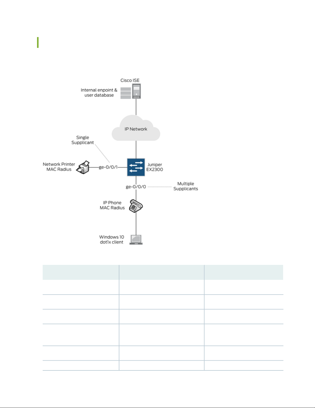
Topology
In this example, we use the following network topology:
11
Here’s more details about the hardware and software components used in this example:
RoleSoftware VersionDevice
Switch and AuthenticatorJunos 18.2R1-S1Juniper EX2300-C-12P
RADIUS Server2.4.0.357 Patch2-18080100Cisco ISE
Supplicant (MAC Radius)SIP/5.5.1.11526/22-Nov-16 15:05Polycom VVX 310 IP Phone
Windows 10 Professional
2018-08-22
Supplicant (Dot1x)All recommended patches as of
Supplicant (MAC Radius)N/ANetwork Printer
Supplicant (MAC Radius)0.6.18981Juniper Mist AP43
Page 12

All users and endpoints are stored in the internal Cisco ISE database.
For external user database integration such as Microsoft Active Directory, LDAP and Certificate Based
Authentication, refer to the Cisco Identity Services Engine Administrator Guide, Release 2.4.
Step-by-Step Procedure
1.
Import the Juniper Wired Device Profile | 12
2.
Add EX Switches to the Juniper Device Profile | 13
3.
Create Authorization Profiles | 14
4.
Create Endpoint Identity Groups | 18
5.
Add Endpoints | 19
6.
Create User Identity Groups | 20
7.
Add Users | 21
12
8.
Set Authentication Policies | 25
9.
Set Authorization Policies | 27
10.
Configure a Cisco ISE Policy to Enable Guest Access | 29
11.
Configure a Colorless Port Using IETF Egress-VLAN-ID Attributes | 34
12.
Configure the 802.1X Protocol on the EX Switch | 41
13.
Configure Windows 10 | 42
Import the Juniper Wired Device Profile
Assuming you’ve got Cisco ISE up and running on your network, the first thing you’ll need to do is add a
Juniper EX switch device profile.
1. Download the latest Juniper EX Switch Device Profile for Cisco ISE (validated with Cisco ISE 2.7).
2. In Cisco ISE, choose Administration > Network Resources > Network Device Profiles.
3. Click Import and select the Juniper EX switch device profile you downloaded in step 1. Once you import
the Juniper network device profile, it will be listed in the Cisco ISE Network Device Profiles list as
Juniper_Wired.
Page 13
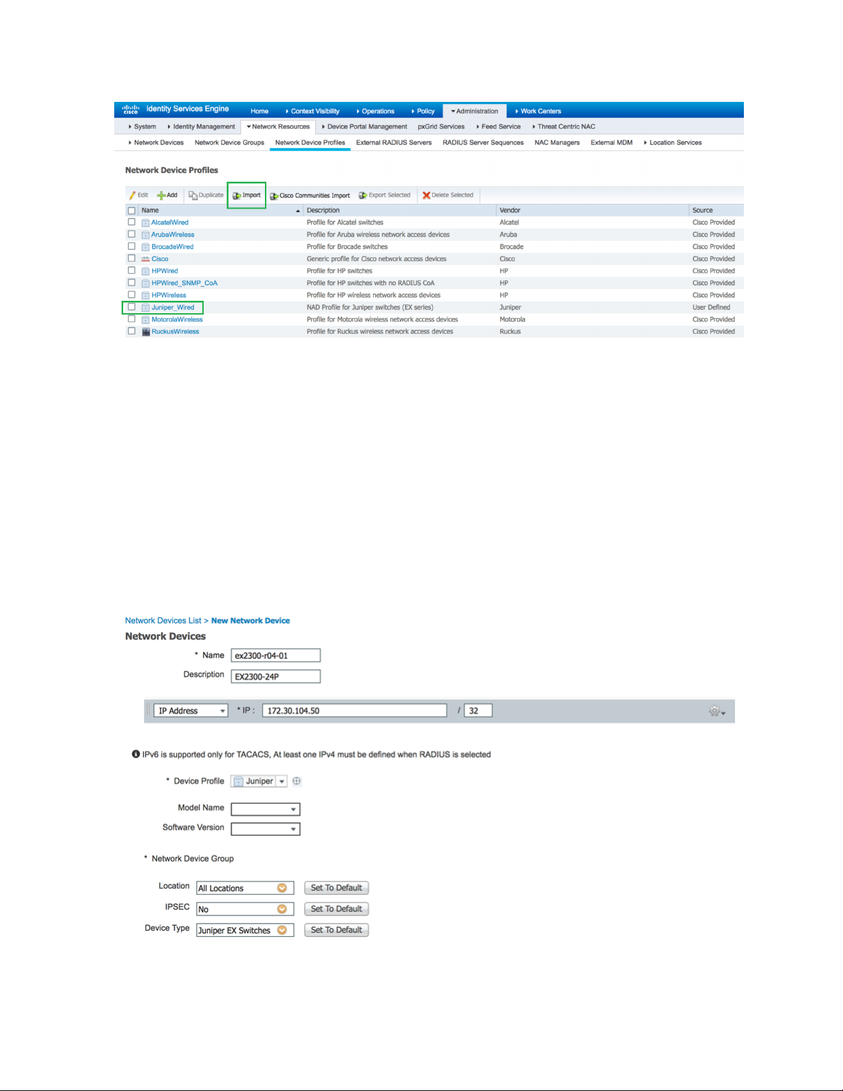
Add EX Switches to the Juniper Device Profile
You can add your EX switches individually, or as an IP address range.
13
1. In Cisco CSE, choose Administration > Network Resources > Network Devices.
2. In the Network Device screen, select the Juniper_Wired device profile.
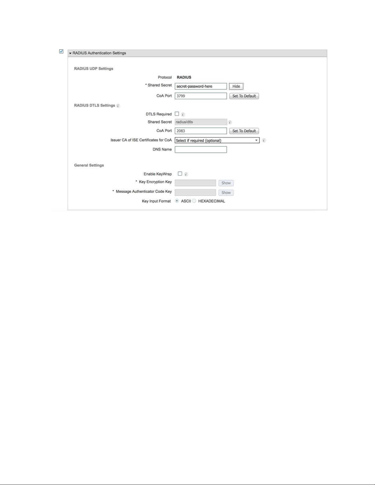
3. Give a name and IP address for your EX switch. If you are adding multiple EX switches, you can specify
an IP address range.
4. Specify a RADIUS password. You’ll need this later when configuring the EX switches.
Page 14
14
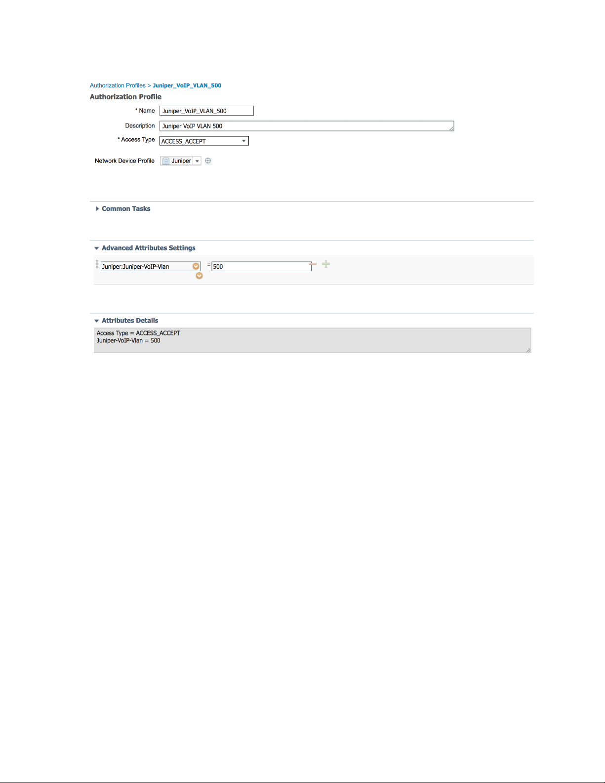
Create Authorization Profiles
Authorization profiles allow you to apply different attributes to users or endpoints. You can change the
VLAN by name or by VLAN ID. You can also assign a firewall filter that you have already configured on
the switch. In this example, we create four authorization profiles:
Juniper_VoIP_VLAN_500
•
Juniper_VoIP_VLAN_100
•
Juniper_VoIP_VLAN_100_ACL
•
Juniper_VoIP_VLAN_100_dACL
•
The first profile sets the VoIP VLAN to 500 using the Juniper-VoIP-VLAN attribute.
1. In Cisco ISE, choose Policy > Results, then from the left pane, choose Authorization > Authorization
Profiles.
2. Name the profile Juniper_VoIP_VLAN_500.
3. Set the VLAN ID/Name to 500.
4. Click Add.
Page 15
15
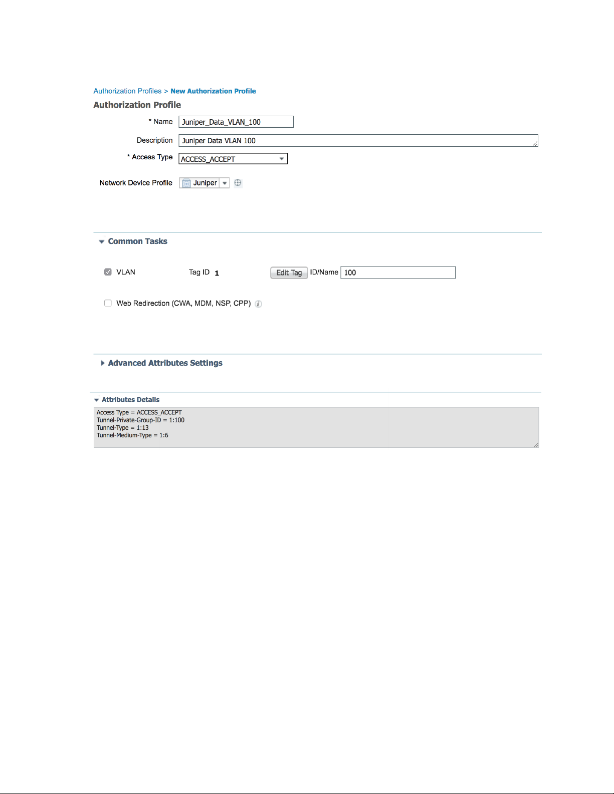
The second authorization profile sets the Data VLAN to 100 using the standard RADIUS attribute for
VLAN ID.
1. In Cisco ISE, choose Policy > Results, then from the left pane, choose Authorization > Authorization
Profiles.
2. Name the profile Juniper_VoIP_VLAN_100.
3. Set the VLAN ID/Name to 100.
4. Click Add.
Page 16
16
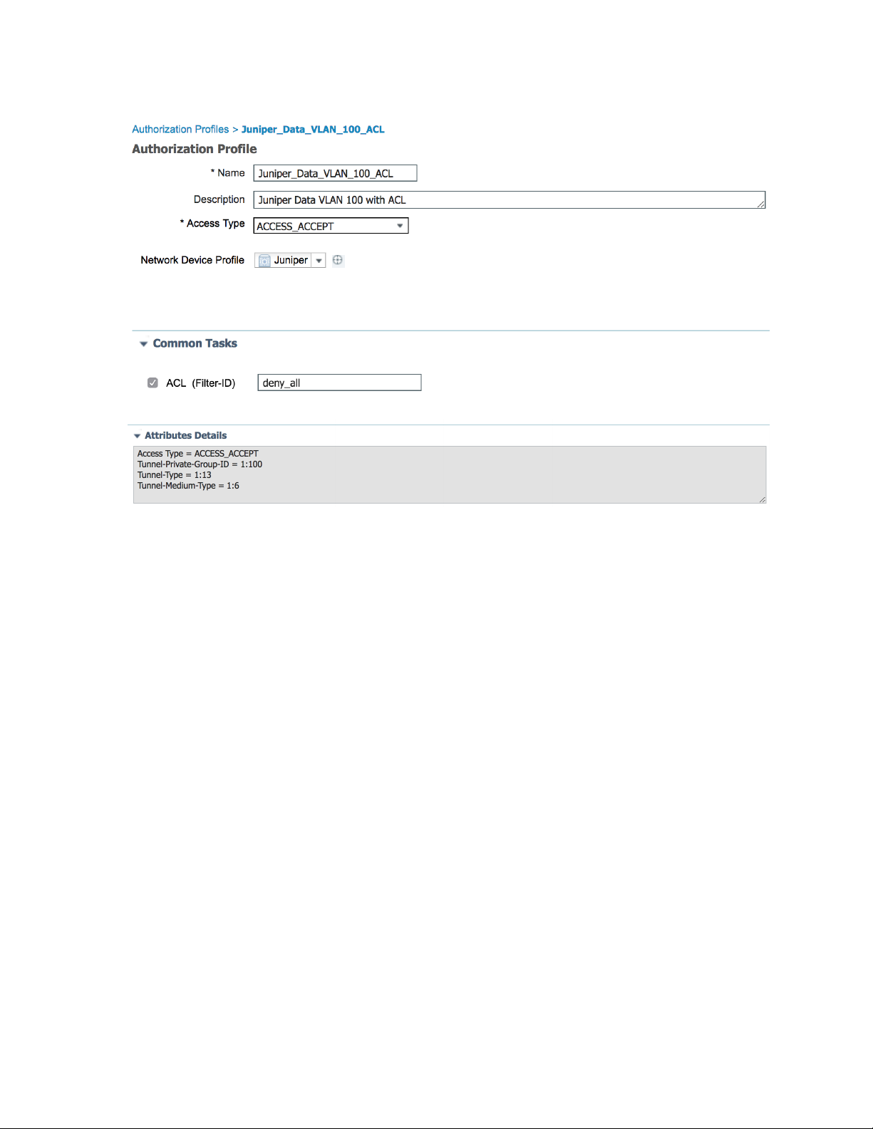
The third profile sets the Data VLAN to 100 and applies a local firewall filter/ACL to the supplicant. This
firewall filter/ACL must already be configured on the switch. The firewall filter/ACL is applied using the
standard Filter-ID radius attribute. Enter the name of the local filter configured on the switch.
1. In Cisco ISE, choose Policy > Results, then from the left pane, choose Authorization > Authorization
Profiles.
2. Name the profile Juniper_VoIP_VLAN_100_ACL.
3. Under Common Tasks, set ACL (Filter-ID) to deny-all.
4. Set the VLAN ID/Name to 100.
5. Click Add.
Page 17
17
Page 18
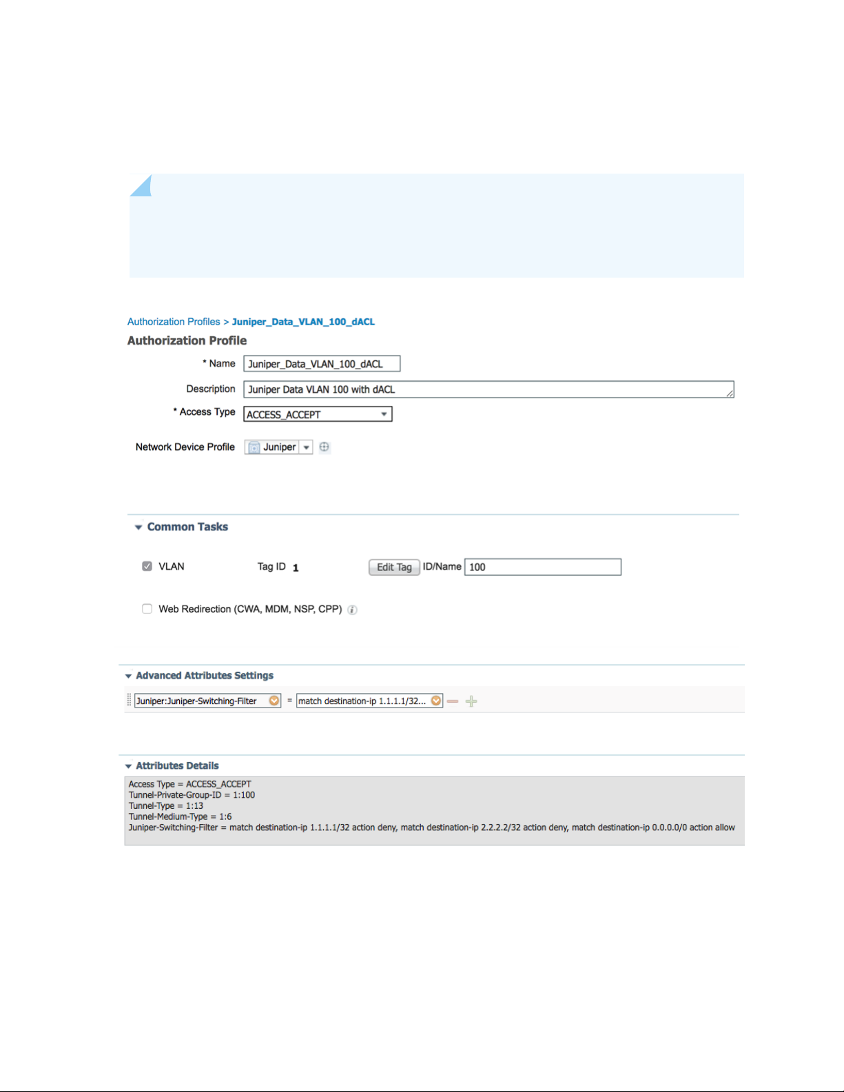
The fourth authorization profile sets the Data VLAN to 100 and applies a dynamic/downloadable firewall
filter/ACL to the supplicant. This firewall filter/ACL is created dynamically, so you don’t need to configure
it locally on the switch. This authorization profile uses the Juniper-Switching-Filter attribute.
NOTE: The syntax and feature sets differ from regular Junos firewall filters/ACLs. Multiple
entries are separated by commas. See Juniper-Switching-Filter VSA Match Conditions and Actions
for information about the syntax.
18
Create Endpoint Identity Groups
Endpoints, such as IP Phones, can be grouped together in endpoint identity groups to make it easier to
apply common attributes, for example, VoIP VLAN.
Page 19

1. In Cisco ISE, choose Administration > Groups > Endpoint Identity Groups.
2. Click Add.
3. Enter a Name and Description under Endpoint Identity Group.
4. Click Submit.
Add Endpoints
19
The Polycom IP Phone in this setup is not configured for dot1x authentication. Instead, we rely on MAC
RADIUS and MAC Authentication Bypass (MAB).
1. In Cisco ISE, choose Context Visibility > Endpoints.
2. Click +.
3. Add the IP Phone’s MAC address and assign it a policy group.
4. Click Save.
Page 20

20
Create User Identity Groups
User Identity Groups allow you to apply specific attributes to users that are members of the group. In this
example, we create three new User Identity Groups:
VLAN_100_User_ID_Group
•
VLAN_100_ACL_User_ID_Group
•
VLAN_100_dACL_User_ID_Group
•
1. In Cisco ISE, choose Administration > Groups > User Identity Groups.
2. Click Add.
3. Enter a name for the User Identity Group and click Submit.
Page 21

Add Users
In this example, we create three local users named user1, user2 and user3. Each user is assigned to a
different User Identity Group.
212223
1. In Cisco ISE, choose Administration >Identity Management.
2. Click Add.
3. Enter a name and login password.
4. From the User Groups drop-down list, choose the User Identity Group that you want to assign to the
new user.
In this example, we assign the new users to these User Identity Groups:
user1 to VLAN_100_User_ID_Group
•
user2 to VLAN_100_ACL_User_ID_Group
•
user3 to VLAN_100_dACL_User_ID_Group
•
Page 22

Page 23

Page 24

24
Here’s an overview of the three users we just created:
Page 25

Set Authentication Policies
The authentication policy contains three entries per default.
The predefined MAB and dot1x rules have conditions that are tied to the network device profile. When
requests come from a Juniper device, the switch automatically uses the attributes configured in the Juniper
network device profile to authenticate a MAB and dot1x request. The authentication policy named Default
contains a default network access policy for allowed protocols. This network access policy is compatible
with Juniper EX switches.
In this example, we use the Default authentication policy.
1. Choose Policy > Policy Sets.
2. Click > to the far right of the Default policy set and choose Default Network Access from the drop-down
box.
25
Page 26

Cisco ISE Default Network Access Profile
Here’s the Cisco ISE configuration for the Default Network Access profile for Juniper EX switches.
26
Page 27

Set Authorization Policies
The order of the authorization policies is important and may vary depending on your setup. Make sure
that you don’t have more general rules above the rules you are about to create, otherwise they won’t
match.
In this example, we create four new rules, each with three conditions:
VLAN 500 for Polycom IP Phones connected to Juniper EX Switches
•
VLAN 100 for dot1x users connected to Juniper EX Switches
•
VLAN 100 with ACL for dot1x users connected to Juniper EX Switches
•
VLAN 100 with dACL for dot1x users connected to Juniper EX Switches
•
1. Expand Authorization Policy and click the + button in the top left corner of the screen.
2. Enter a name for the rule, for example, VLAN 500 for Polycom IP Phones connected to Juniper EX
Switches.
27
3. Click condition to open the Condition Studio.
4. Drag and drop from the library on the left side to the editor on the right side. Build the different
attributes you want to match on.
5. When you’re finished don’t click Save. Instead, click the USE button in the bottom right corner.
Here’s an example of the Conditions Studio:
Page 28

28
Let’s analyze these four new rules. Each rule has three conditions. The first two conditions are the same,
but the third condition matches on a different attribute. A rule is applied to a port only when all three
conditions are met.
Page 29

Then the switch assigns
the port/supplicant toIf the endpointRule
29
VLAN 500 for Polycom IP Phones
connected to Juniper EX Switches
VLAN 100 for dot1x users
connected to Juniper EX Switches
VLAN 100 with ACL for dot1x
users connected to Juniper EX
Switches
VLAN 100 with dACL for dot1x
users connected to Juniper EX
Switches
request comes from a Juniper EX switch AND the
endpoint is in the Polycom-IP-Phone group
request comes from a Juniper EX switch AND the
endpoint is in the VLAN_100_User_ID_Group
Passes network access authentication AND the
request comes from a Juniper EX switch AND the
endpoint is in the VLAN_100_ACL_User_ID_Group
Passes network access authentication AND the
request comes from a Juniper EX switch AND the
endpoint is in the VLAN_100_dACL_User_ID_Group
Voice VLAN 500Passes network access authentication AND the
Data VLAN 100Passes network access authentication AND the
Data VLAN 100 and an
ACL
Data VLAN 100 and a
dynamic/downloadable
ACL
Configure a Cisco ISE Policy to Enable Guest Access
For guest access use-cases involving the Cisco ISE guest portal, Juniper EX switches support
Juniper-CWA-Redirect-URL VSA along with a special Filter-Id JNPR_RSVD_FILTER_CWA to redirect
unknown guest clients to the Cisco ISE portal. The following diagram outlines the guest access flow with
Cisco ISE:
Page 30

30
Here’s the Juniper EX switch configuration for this scenario:
Page 31

Here’s how to configure a Cisco ISE policy to enable guest access:
1. In Cisco ISE, choose Policy Sets > Wired Access.
2. Verify that the WIRED MAB authentication policy is set to Internal Endpoints for the data store and
Continue for If User not found and If Process fail.
31
3. Create two authorization policies. If the client (MAC) already registered in the GuestEndpoints Identity
Group, Cisco ISE will send a “Permit Access” message. Otherwise, Cisco ISE will send a CWA Redirect
attribute to move the client to the Cisco ISE guest portal.
Here’s an example of the Guest Redirect Wired authorization profile configuration.
Page 32

NOTE: You’ll need to configure a static IP address instead of the FQDN for the CWA Filter
to work. Alternatively, you can use a Juniper-Switching-Filter with a FQDN-based redirect
URL.
32
4. Verify the configuration in the EX switch CLI:
Page 33

33
Once the client authenticates with Cisco ISE, Cisco ISE sends a CoA. Upon re-authentication, the CLI
output for the EX switch shows a successful MAC Authentication:
Page 34

34
Configure a Colorless Port Using IETF Egress-VLAN-ID Attributes
With Junos 20.4 and above, you can automatically configure switch ports into access/trunk ports and
assign multiple VLANs based on the RADIUS (Cisco ISE) response. For example, you can have a common
port configuration on the switch and then reconfigure it automatically based on the identity of a connecting
device, such as a Mist AP, a printer, or a corporate laptop.
Here’s an example of how to automatically configure a port into a trunk port for Mist AP with an untagged
native VLAN for management:
Page 35

By default, the port is configured as an access port with 802.1X and MAC-Radius enabled.
35
Page 36

Here’s how to create a new profiler policy in Cisco ISE to auto-profile Mist APs based on Mist MAC-OUI.
The profiler policy will send the full switch port configuration (trunk, with native vlan 51 and all the other
required VLAN tagged).
1. Choose Policy > Profiling > Profiling Policies > Create New.
36
2. Create two rules using Radius_Calling_Station_ID_STARTSWITH 5c-5b-35 or d2-20-b0 to specify the
current Mist MAC OUIs.
3. Save your profiler policy.
4. Navigate to your profiler policy and add another authorization rule:
Page 37

The authorization profile looks like this:
37
Page 38

38
How did we get all the numbers above? We used the following formula:
1. Create hex values for each VLAN you want to push in access-accept. The hex format is 0x31000005.
The first seven characters can either be 0x31000 (tagged) or 0x32000 (untagged). The last three
characters are the actual VLAN ID converted to hex. You can use a Decimal to hexadecimal converter
to figure out the hexadecimal value. For example, to send untagged VLAN 51, the value is 0x32000033.
2. Once you enter this hex value, convert the whole value back to decimal. You can use this Hexidecimal
to decimal converter to figure out the decimal value.
Page 39

In this example, if you convert 0x32000033 to decimal, the value is 52428851.
3. Configure the Cisco ISE authorization profile using the decimal value.
39
4. Plug in a Mist AP and verify the output:
Page 40

40
Page 41

Configure the 802.1X Protocol on the EX Switch
41
Page 42

42
Configure Windows 10
1. Press the Windows key on your keyboard and search for services.msc.
2. Right click to enable the Wired Autoconfig service.
Page 43

43
3. Choose Control Panel/Settings > Network and Internet > Ethernet > Change Adapter Settings.
4. Right click on the adapter used for your wired connection.
5. Click the Authentication tab and then click Settings.
Page 44

44
6. Clear the check box to verify the server identity certificate.
CAUTION: This is for testing purposes only. Never disable this in production.
Always provision your clients with trusted CA certifications.
7. Click OK.
Page 45

45
NOTE: In a production environment, you need to install the Cisco ISE certificate. Refer to
the Cisco Identity Services Engine Administrator Guide, Release 2.4.
Page 46

46
8. Select User Authentication mode and click Replace Credentials.
9. Enter the username and password, for example user1, user2 or user3.
10. Click OK.
Page 47

47
Testing and Validation
IN THIS SECTION
Verify IP Phone Authentication Status | 48
Verify Connections to Windows 10 Clients | 50
Page 48

Verify IP Phone Authentication Status
1. After connecting the IP Phone to port ge-0/0/0, run the show dot1x interface ge-0/0/0 command to
verify it is authenticated using MAC Authentication Bypass.
2. Run the show dot1x interface ge-0/0/0 detail command to view the detailed output and verify that
you are using MAC Radius to authenticate the IP Phone.
48
3. Run the show ethernet-switching interface ge-0/0/0 command to verify that Cisco ISE has applied
Voice VLAN 500 as a tagged VLAN on port ge-0/0/0.
Page 49

4. Run the show lldp neighbors interface ge-0/0/0 command to view the LLDP output and verify that
the IP Phone is using tagged VLAN 500 for Voice.
49
5. Verify authentication status in Cisco ISE. Choose Operations > Live Logs.
Page 50

6. Choose Operations > Live Sessions.
Verify Connections to Windows 10 Clients
IN THIS SECTION
Verify User 1 | 50
Verify User 2 | 52
Verify User 3 | 55
50
Verify CoA Session Disconnect with Port Bounce | 57
Verify User 1
1. Enter the dot1x credentials in Windows for user1 and connect the PC to the IP Phone. Verify that
User1 is authenticated:
2. Verify that Cisco ISE has applied Data VLAN 100 to port ge-0/0/0:
Page 51

51
3. View the Cisco ISE logs. Choose Operations > Live Logs.
Page 52

4. Choose Operations > Live Sessions
Verify User 2
1. Change credentials in Windows to user2.
2. Verify that user2 is authenticated.
52
3. Verify that Cisco ISE has applied Data VLAN 100, and also applied the locally configured firewall
filter/ACL called deny_all.
Page 53

53
4. Verify that the firewall filter is active for the supplicant.
Page 54

54
5. View the Cisco ISE logs. Choose Operations -> Live Logs. Note the different authorization policy applied
for user2, Data VLAN 100 + ACL deny_all.
6. Choose Operations > Live Sessions.
Page 55

Verify User 3
1. Change credentials in Windows to user3.
2. Verify that user3 is authenticated.
3. Verify that Cisco ISE has applied Data VLAN 100, and also applied a dynamic/downloadable firewall
filter/ACL to the supplicant.
55
4. Verify that the firewall filter is active for the supplicant. The terms should be in this order:
t0 is the first term
•
t1 is the second term
•
T term without a t-name is the last term to allow all traffic
•
Page 56

5. View the Cisco ISE logs. Choose Operations > Live Logs. Note the different authorization policy applied
for user2, Data VLAN 100 + dACL.
6. Choose Operations > Live Sessions.
7. Verify that user3 is authenticated.
56
8. View the Cisco ISE log. Choose Operations > Live Sessions > Show CoA Actions > Session termination
for user3.
9. Click Show CoA Actions and session termination.
10. Verify that the user3 session is terminated.
Page 57

Verify CoA Session Disconnect with Port Bounce
1. Verify that the IP Phone is authenticated. (0004f228b69d1)
2. View the Cisco ISE log. Choose Operations > Live Sessions > Show CoA Actions > Session termination
for IP Phone.
3. Click Show CoA Actions then choose Session termination with port bounce.
57
4. Run the command show dot1x interface and notice that all sessions are now terminated because the
port was bounced.
Page 58

58
 Loading...