

Page 1

C-series Platforms
C2000 and C4000
Hardware Quick Start Guide
Juniper Networks, Inc.
1194 North Mathilda Avenue
Sunnyvale, CA 94089
USA
408-745-2000
www.juniper.net
Part Number: 530-018157-01, Revision A00
Page 2
Product Reclamation and Recycling Program
Juniper Networks is committed to environmentally responsible behavior. As part of this commitment, we work to comply with
environmental standards such as the European Union’s Waste E le ctric al and Electronic Equipment (WEEE) Directive and Restriction of
Hazardous Substances (RoHS) Directive.
These directives and other similar regulations from countries outside the European Union regulate electronic waste management and
the reduction or elimination of specific hazardous materials in electronic products. The WEEE Directive requires electrical and
electronics manufacturers to provide mechanisms for the recycling and reuse of their products. The RoHS Directive restricts the use of
certain substances that are commonly found in electronic products today. Restricted substances include heavy metals, including lead,
and polybrominated materials. The RoHS Directive, with some exemptions, applies to all electrical and electronic equipment.
In accordance with Article 11(2) of Directive 2002/96/EC (WEEE), products put on the market after 13 August 2005 are marked with the
following symbol or include it in their documentation: a crossed-out wheeled waste bin with a bar beneath.
g002313
Juniper Networks provides recycling support for our equipment worldwide to comply with the WEEE Directive. For recycling
information, send e-mail to
recycling@juniper.net
indicating the type of Juniper Networks equipment that you wish to dispose of and the
country where it is currently located, or contact your Juniper Networks account representative.
Products returned through our reclamation process are recycled, recovered, or disposed of in a responsible manner. Our packaging is
designed to be recycled and should be handled in accordance with your local recycling policies.
Page 3

Quick Start Overview
This guide is an abridged version of the C-series hardware installation
documentation and is intended for experienced installers who want to expedite the
installation process. Follow the steps in this guide to get your C-series Controller up
and running quickly.
1. Preparing the Site
Ensure that your installation site meets the requirements in Table 1.
Table 1: C2000 Model and C4000 Model Specifications
Category Specification
Temperature Operating: 50° to 104°F (10° to 40°C)
Relative humidity
Heat dissipation
AC i nput
Power required
AC line freque ncy
Power
Space requirements
C2000 and C4000 Quick Start Guide
Storage: –40° to 158°F (–40° to 70°C)
Operating: 8% to 90% (noncondensing)
Storage: 5% to 95% (noncondensing)
C2000 model—500 W, 1706 BTU/hour maximum
C4000 model—700 W, 2389 BTU/hour maximum
100-240 VAC @ –5 A
50-60 Hz
C2000 model—500 W; C4000 model—700 W
3 feet (90 cm) behind system or rack.
Do not block air vents on front or back of the system.
To complete the installation of the router in a rack, you need:
A Phillips screwdriver
A utility knife
Eight 10-32 x 3/8 Phillips screws (provided) for each model to be installed
For detailed installation guidelines and considerations, see C2000 and C4000
Hardware Guide, Chapter 9, Installation Guidelines and Requirements.
Quick Start Overview 1
Page 4
C2000 and C4000 Quick Start Guide
2. Installing the System
When installing the system on a table top or in any other freestanding mode, be
sure to leave enough space around the system for adequate ventilation. Position the
system with easy access to the connections that it needs for power, local
communications, and remote communications.
For rack installation, we recommend that you use a standard EIA distribution rack.
WARNING: Three people are required to install the router in a rack: two to lift the
system into position and one to screw it to the rack.
To install the system in the rack:
1. With one person standing on the left side of the chassis and another standing
on the right side, lift the router into the rack.
2. Position the router in its designated location in the equipment rack. Make sure
the holes of the mounting brackets align evenly with the holes of the equipment
rack on both sides.
3. Starting at the bottom of the system, secure the router in the equipment rack
by using the 10-32 x 3/8 Phillips screws.
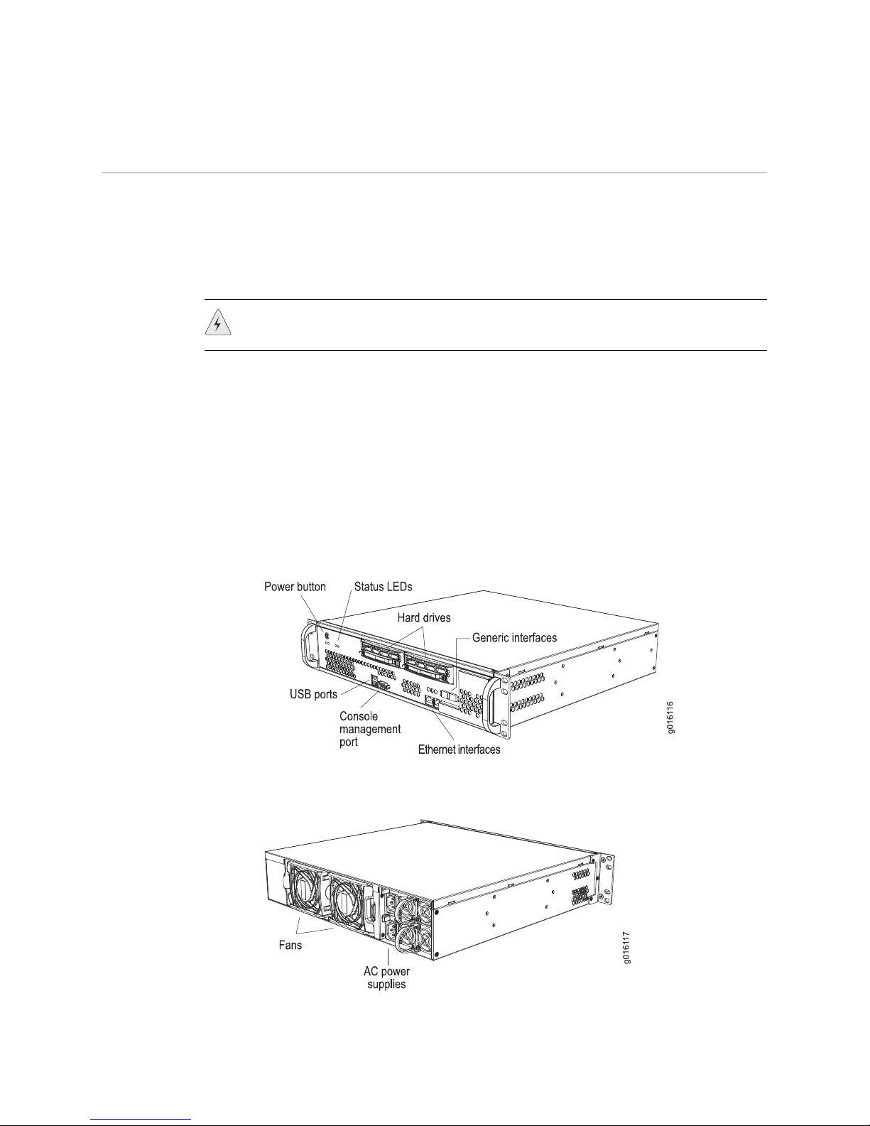
Figure 1: C2000, Front Oblique View
Figure 2: C2000, Rear Oblique View
2 2. Installing the E320 Router
Page 5

Figure 3: C4000, Front Oblique View
Figure 4: C4000, Rear Oblique View
C2000 and C4000 Quick Start Guide
3. Cabling the System
Before powering up the system, you must set up a management console. The
console enables you to communicate with your system during the power-up
process and to manage your system using the command-line interface (CLI).
When connecting a console directly to the system, use a cable appropriate for your
terminal connector. The cable must have a female DB-9 connector to attach to the
RS-232 port on the system.
Management Ports
The management section of the system has three ports for management access:
Two 10/100Base-T Ethernet ports—Each accepts an RJ-45 (male) connector,
One RS-232 management port—Accepts a DB-9 (female) connector. This port
providing an out-of-band connection for LAN access through a Telnet session,
SSH, or SNMP.
provides direct CLI access from a console terminal.
3. Cabling the System 3
Page 6

C2000 and C4000 Quick Start Guide
Ethernet Interfaces
Connecting to a Network
1. Insert an Ethernet cable (RJ-45) connector into the 10/100Base-T (RJ-45) port
(Figure 1 and Figure 3) on the system until it clicks into place.
2. Connect the other end of the cable to the appropriate Ethernet network for an
out-of-band connection.
Connecting to a Console Terminal
1. Insert a female DB-9 connector into the RS-232 port (Figure 1 and Figure 3),
and tighten the screws.
2. Connect the other end of the cable to your terminal’s serial port (VT100/ANSI).
Port ETH0 and ETH1 on the C2000 model and the C4000 model accept RJ-45
10/100/1000Base-T Ethernet (copper) interfaces. Port ETH2 and port ETH3 on the
C2000 model and the C4000 model accept SFPs. See Figure 1 and Figure 3.
Power
After you have correctly cabled the system, you can then attach the power cord. See
Figure 2 and Figure 4. See C2000 and C4000 Hardware Guide, Chapter 7, System
Specifications for complete power requirements for the system.
1. Insert the power cord into the AC power IEC receptacle.
2. Insert the other end of the power cord into an appropriate AC power source.
NOTE: To provide redundancy, do not terminate Power A and Power B leads at the
same power source.
4. Powering On the C-series Platform
For specifications on the electrical requirements for the system, see C2000 and
C4000 Hardware Guide, Chapter 7, System Specifications.
1. Verify that the power source is operational and turned on.
2. Inspect all power connections to the system.
3. Confirm that all connections are secure.
4. Press the PWR button.
5. Monitor the LEDs to verify that the system is booting properly.
When the prompt appears on the system console, you can log in and configure
the system.
4 4. Powering On the C-series Platform
Page 7

5. Setting Up Management Access and Logging In
You can monitor and manage the system through either of these methods:
Console terminal—Connect a console (PC, Macintosh, or UNIX workstation)
directly to the system's RS-232 serial port.
Remote console—Connect 10/100Base-T port (ETH0) to an Ethernet network,
and run SSH or Telnet from a remote console.
To communicate with the system, you must have a terminal emulation program
running on your PC or Macintosh. You can use any terminal emulation program,
such as HyperTerminal. A UNIX workstation can use the emulator TIP.
To log in to the system:
1. Start your terminal emulation program using the following settings:
C2000 and C4000 Quick Start Guide
Bits per second: 9600
Data bits: 8
Parity: None
Stop bits: 1
Flow control: none
2. Enter the username.
SRC-PE Release 7.0 [B.7.0.0-12]
localhost login:root
3. Enter the password.
localhost password:password
--- SRC CLI 7.0 build CLI.B.7.0.0.012
(c) 2005-2007 Juniper Networks Inc.
root@localhost>
You are now logged in as root user.
6. Configuring the Juniper Networks Database
Each C-series platform contains a Juniper Networks database. The database stores
SRC data, sample data, configuration information, and user profiles. You must
enable the Juniper Networks database the first time you power on the system.
Typically, you run the database in standalone mode only in testing environments. In
standalone mode, the database does not communicate with other Juniper Networks
databases; there is no data distribution and no redundancy.
In the following example, a standalone database is enabled. For more information
about community mode, see SRC–PE Getting Starting Guide, Chapter 10, Managing
the Juniper Networks Database.
5. Setting Up Management Access and Logging In 5
Page 8

C2000 and C4000 Quick Start Guide
To enable a Juniper Networks database to run in standalone mode:
1. From configuration mode, access the configuration statement that configures
the Juniper Networks database.
user@host# edit system ldap server
2. Enable standalone mode.
[edit system ldap server]
user@host# set stand-alone
7. Configuring Hostname and Domain Parameters
To set hostname and domain parameters:
1. Enter configuration mode.
root@host> edit
2. Configure the hostname.
[edit]
root@host# set system host-name host-name
For example:
[edit]
root@host# set system host-name my-hostname
3. Configure either a list of domain names to search, or create the domain name.
We recommend configuring a list of domain names to search.
To configure a list of domain names to search:
[edit]
root@host# set system domain-search [domain-name1, domain-name2, ...]
For example:
[edit]
root@host# set system domain-search [my-domain.juniper.net
domain.juniper2.net]
To configure the domain name:
[
edit]
root@host# set system domain-name domain-name
For example:
[edit]
root@host# set system domain-name my-domain.juniper.net
6 7. Configuring Hostname and Domain Parameters
Page 9

8. Configuring the System for Remote Access
To allow remote access to the system, you must configure the generic interfaces.
You can specify an IP address with mask or a broadcast address with mask for an
interface. For more information, see SRC–PE Getting Starting Guide, Chapter 7,
Configuring Remote Access to an SRC Platform.
To configure the generic interfaces:
1. From configuration mode, access the configuration statement that configures
the interface.
user@host# edit interfaces eth0
2. Specify the unit, family, and IP address for the interface.
[edit interfaces eth0]
user@host# set unit number family inet address address
C2000 and C4000 Quick Start Guide
For example, to configure an interface with only an IP address:
[edit interfaces eth0]
user@host# set unit 0 family inet address 192.2.0.10/24
3. (Optional) Specify the broadcast address for the interface.
[edit interfaces eth0]
user@host# set unit number family inet broadcast broadcast
For example, to configure an interface with only a broadcast address:
[edit interfaces eth0]
user@host# set unit 0 family inet broadcast 192.2.0.255
4. Verify the interface configuration.
[edit interfaces eth0]
user@host# show
unit 0 {
family {
inet {
broadcast 192.2.0.255;
}
}
}
8. Configuring the System for Remote Access 7
Page 10

C2000 and C4000 Quick Start Guide
9. Configuring the System to Accept SSH and Telnet Connections
To configure the system to accept SSH connections:
1. From configuration mode, access the
level.
2. (Optional) Specify whether or not to allow root login through SSH.
[edit system services ssh]
user@host> set root-login (allow | deny | deny-password)
where:
allow
–Allow users to log in to the C-series platform as root through SSH.
deny
–Disable users from logging in to the system as root through SSH.
deny-password
the authentication method (for example, RSA authentication) does not
require a password. (Default)
To configure the system to accept Telnet connections:
In edit mode, type the following command.
[edit]
user@host# set system services telnet
10. Adding an Admin User Account
[edit system services ssh]
–Allow users to log in to the system as root through SSH when
hierarchy
Although
root
access is used for initial configuration of the system, user accounts
are used to enter commands and statements at the CLI. Therefore, you must set up
an admin account to allow further configuration. You can use a built-in class, such
as super-user.
To configure an account for an administrative user:
1. Create an account for an administrative user.
[edit]
user@host # edit system login user user
For example:
[edit]
user@host # edit system login user myadmin
2. Set the class for the administrative user to the login class that you created.
[edit system login user myadmin]
user@host # set class class
8 9. Configuring the System to Accept SSH and Telnet Connections
Page 11

C2000 and C4000 Quick Start Guide
For example:
[edit system login user myadmin]
user@host # set class super-user
3. Specify the name of the administrative user.
[edit system login user myadmin]
user@host # set full-name “John Doe”
4. Set the CLI editing level to expert.
[edit system login user myadmin]
user@host# set level expert
5. (Optional) Specify that a space be used for command completion.
[edit system login user myadmin]
user@host # set complete-on-space on
6. Verify that the configuration for the administrative user is correct.
[edit system login user myadmin]
user@host# show
class super-user;
full-name "John Doe";
uid 506;
gid 100;
level expert;
complete-on-space on;
7. Set the password of the user.
[edit]
user@host# edit system login user myadmin authentication
[edit system login user myadmin authentication]
user@host# set plain-text-password
Troubleshooting
If you encounter a system problem, you can open a support case with the Case
Manager link at
http://www.juniper.net/support/ or call 1-888-314-JTAC (from the
United States, Canada, or Mexico) or 1-408-745-9500 (from elsewhere).
Configuring and Operating the C-series Platform
You are now ready to configure your system. See the C2000 and C4000 Hardware
Guide and the SRC–PE Getting Started User Guide for more information about using
the C-series platform.
Troubleshooting 9
Page 12

C2000 and C4000 Quick Start Guide
Figure 5: C2000, Front View
Figure 6: C4000, Front View
Obtaining Documentation
To obtain the most current version of all Juniper Networks technical documentation,
see the products documentation page on the Juniper Networks Web site at
http://www.juniper.net/
To order printed copies of Juniper Networks technical documents, or to order a
documentation CD, which contains this manual, contact your sales representative.
Part Number: 530-018157-01,
Revision A00
Juniper Networks, Inc.
1194 North Mathilda Avenue
Sunnyvale, CA 94089 USA
Phone 408 745 2000
or 888 JUNIPER
Fax 408 745 2100
Juniper Networks, the Juniper Networks logo, NetScreen, NetScreen Technologies, the NetScreen logo, NetScreen-Global
Pro, ScreenOS, and GigaScreen are registered trademarks of Juniper Networks, Inc. in the United States and other
countries.
The following are trademarks of Juniper Networks, Inc.: ERX, ESP, E-series, Instant Virtual Extranet, Internet Processor,
J2300, J4300, J6300, J-Protect, J-series, J-Web, JUNOS, JUNOScope, JUNOScript, JUNOSe, M5, M7i, M10, M10i, M20,
M40, M40e, M160, M320, M-series, MMD, NetScreen-5GT, NetScreen-5XP, NetScreen-5XT, NetScreen-25, NetScreen-50,
NetScreen-204, NetScreen-208, NetScreen-500, NetScreen-5200, NetScreen-5400, NetScreen-IDP 10, NetScreen-IDP
100, NetScreen-IDP 500, NetScreen-Remote Security Client, NetScreen-Remote VPN Client, NetScreen-SA 1000 Series,
NetScreen-SA 3000 Series, NetScreen-SA 5000 Series, NetScreen-SA Central Manager, NetScreen Secure Access,
NetScreen-SM 3000, NetScreen-Security Manager, NMC-RX, SDX, Stateful Signature, T320, T640, and T-series. All other
trademarks, service marks, registered trademarks, or registered service marks are the property of their respective
owners. All specifications are subject to change without notice.
Products made or sold by Juniper Networks (including the ERX-310, ERX-705, ERX-710, ERX-1410, ERX-1440, M5, M7i,
M10, M10i, M20, M40, M40e, M160, M320, and T320 routers, T640 routing node, and the JUNOS, JUNOSe, and
SDX-300 software) or components thereof might be covered by one or more of the following patents that are owned by
or licensed to Juniper Networks: U.S. Patent Nos. 5,473,599, 5,905,725, 5,909,440, 6,192,051, 6,333,650, 6,359,479,
6,406,312, 6,429,706, 6,459,579, 6,493,347, 6,538,518, 6,538,899, 6,552,918, 6,567,902, 6,578,186, and 6,590,785.
Copyright © 2007, Juniper Networks, Inc.
All rights reserved. Printed in USA.
Revision History
6 April 2007—Revision 1
 Loading...