

Page 1

BX7000 Multi-Access
Gateway
Hardware Guide
This product includes the Envoy SNMP Engine, developed by Epilogue Technology, an Integrated Systems Company. Copyright ©
1986-1997, Epilogue Technology Corporation. All rights reserved. This program and its documentation were developed at private expense,
and no part of them is in the public domain.
This product includes memory allocation software developed by Mark Moraes, copyright © 1988, 1989, 1993, University of Toronto.
This product includes FreeBSD software developed by the University of California, Berkeley, and its contributors. All of the documentation
and software included in the 4.4BSD and 4.4BSD-Lite Releases is copyrighted by the Regents of the University of California. Copyright ©
1979, 1980, 1983, 1986, 1988, 1989, 1991, 1992, 1993, 1994. The Regents of the University of California. All rights reserved.
GateD software copyright © 1995, the Regents of the University. All rights reserved. Gate Daemon was originated and developed through
release 3.0 by Cornell University and its collaborators. Gated is based on Kirton’s EGP, UC Berkeley’s routing daemon (routed), and DCN’s
HELLO routing protocol. Development of Gated has been supported in part by the National Science Foundation. Portions of the GateD
software copyright © 1988, Regents of the University of California. All rights reserved. Portions of the GateD software copyright © 1991, D. L.
S. Associates.
This product includes software developed by Maker Communications, Inc., copyright © 1996, 1997, Maker Communications, Inc. Juniper
Networks, the Juniper Networks logo, JUNOS, NetScreen, ScreenOS, and Steel-Belted Radius are registered trademarks of Juniper
Networks, Inc. in the United States and other countries. JUNOSe is a trademark of Juniper Networks, Inc. All other trademarks, service
marks, registered trademarks, or registered service marks are the property of their respective owners.
Juniper Networks assumes no responsibility for any inaccuracies in this document. Juniper Networks reserves the right to change, modify,
transfer, or otherwise revise this publication without notice.
Releas e
4.3
August 2011
530-027514-01, Revision 1.0
Copyright © 2011, Juniper Networks, Inc.
Page 2

Products made or sold by Juniper Networks or components thereof might be covered by one or more of the following patents that are
owned by or licensed to Juniper Networks: U.S. Patent Nos. 5,473,599, 5,905,725, 5,909,440, 6,192,051, 6,333,650, 6,359,479, 6,406,312,
6,429,706, 6,459,579, 6,493,347, 6,538,518, 6,538,899, 6,552,918, 6,567,902, 6,578,186, and 6,590,785.
BX7000 Multi-Access Gateway Hardware Guide
Copyright © 2010, Juniper Networks, Inc.
All rights reserved. Printed in USA.
Revision History
JAugust 2011—530-027514-01, Revision 1.0.
The information in this document is current as of the date listed in the revision history.
Year 2000 Notice
Juniper Networks hardware and software products are Year 2000 compliant. The JUNOS software has no known time-related limitations
through the year 2038. However, the NTP application is known to have some difficulty in the year 2036.
ii Copyright © 2010, Juniper Networks, Inc.
Page 3

END USER LICENSE AGREEMENT
READ THIS END USER LICENSE AGREEMENT ("AGREEMENT") BEFORE DOWNLOADING, INSTALLING, OR USING THE SOFTWARE. BY
DOWNLOADING, INSTALLING, OR USING THE SOFTWARE OR OTHERWISE EXPRESSING YOUR AGREEMENT TO THE TERMS
CONTAINED HEREIN, YOU (AS CUSTOMER OR IF YOU ARE NOT THE CUSTOMER, AS A REPRESENTATIVE/AGENT AUTHORIZED TO BIND
THE CUSTOMER) CONSENT TO BE BOUND BY THIS AGREEMENT. IF YOU DO NOT OR CANNOT AGREE TO THE TERMS CONTAINED
HEREIN, THEN (A) DO NOT DOWNLOAD, INSTALL, OR USE THE SOFTWARE, AND (B) YOU MAY CONTACT JUNIPER NETWORKS
REGARDING LICENSE TERMS.
1.The Parties. The parties to this Agreement are (i) Juniper Networks, Inc. (if the Customer's principal office is located in the Americas) or
Juniper Networks (Cayman) Limited (if the Customer's principal office is located outside the Americas) (such applicable entity being
referred to herein as "Juniper"), and (ii) the person or organization that originally purchased from Juniper or an authorized Juniper reseller
the applicable license(s) for use of the Software ("Customer") (collectively, the "Parties").
2.The Software. In this Agreement, "Software" means the program modules and features of the Juniper or Juniper-supplied software, for
which Customer has paid the applicable license or support fees to Juniper or an authorized Juniper reseller, or which was embedded by
Juniper in equipment which Customer purchased from Juniper or an authorized Juniper reseller. "Software" also includes updates, upgrades
and new releases of such software. "Embedded Software" means Software which Juniper has embedded in or loaded onto the Juniper
equipment and any updates, upgrades, additions or replacements which are subsequently embedded in or loaded onto the equipment.
3. License Grant. Subject to payment of the applicable fees and the limitations and restrictions set forth herein, Juniper grants to Customer
a non-exclusive and non-transferable license, without right to sublicense, to use the Software, in executable form only, subject to the
following use restrictions:
a. Customer shall use Embedded Software solely as embedded in, and for execution on, Juniper equipment originally purchased by
Customer from Juniper or an authorized Juniper reseller.
b. Customer shall use the Software on a single hardware chassis having a single processing unit, or as many chassis or processing
units for which Customer has paid the applicable license fees; provided, however, with respect to the Steel-Belted Radius or Odyssey
Access Client software only, Customer shall use such Software on a single computer containing a single physical random access
memory space and containing any number of processors. Use of the Steel-Belted Radius or IMS AAA software on multiple computers
or virtual machines (e.g., Solaris zones) requires multiple licenses, regardless of whether such computers or virtualizations are
physically contained on a single chassis.
c. Product purchase documents, paper or electronic user documentation, and/or the particular licenses purchased by Customer may
specify limits to Customer's use of the Software. Such limits may restrict use to a maximum number of seats, registered endpoints,
concurrent users, sessions, calls, connections, subscribers, clusters, nodes, realms, devices, links, ports or transactions, or require the
purchase of separate licenses to use particular features, functionalities, services, applications, operations, or capabilities, or provide
throughput, performance, configuration, bandwidth, interface, processing, temporal, or geographical limits. In addition, such limits
may restrict the use of the Software to managing certain kinds of networks or require the Software to be used only in conjunction with
other specific Software. Customer's use of the Software shall be subject to all such limitations and purchase of all applicable
licenses.
d. For any trial copy of the Software, Customer's right to use the Software expires 30 days after download, installation or use of the
Software. Customer may operate the Software after the 30-day trial period only if Customer pays for a license to do so. Customer
may not extend or create an additional trial period by re-installing the Software after the 30-day trial period.
e. The Global Enterprise Edition of the Steel-Belted Radius software may be used by Customer only to manage access to Customer's
enterprise network. Specifically, service provider customers are expressly prohibited from using the Global Enterprise Edition of the
Steel-Belted Radius software to support any commercial network access services.
The foregoing license is not transferable or assignable by Customer. No license is granted herein to any user who did not originally purchase
the applicable license(s) for the Software from Juniper or an authorized Juniper reseller.
4. Use Prohibitions. Notwithstanding the foregoing, the license provided herein does not permit the Customer to, and Customer agrees not
to and shall not: (a) modify, unbundle, reverse engineer, or create derivative works based on the Software; (b) make unauthorized copies of
the Software (except as necessary for backup purposes); (c) rent, sell, transfer, or grant any rights in and to any copy of the Software, in any
form, to any third party; (d) remove any proprietary notices, labels, or marks on or in any copy of the Software or any product in which the
Software is embedded; (e) distribute any copy of the Software to any third party, including as may be embedded in Juniper equipment sold
in the secondhand market; (f) use any 'locked' or key-restricted feature, function, service, application, operation, or capability without first
purchasing the applicable license(s) and obtaining a valid key from Juniper, even if such feature, function, service, application, operation, or
capability is enabled without a key; (g) distribute any key for the Software provided by Juniper to any third party; (h) use the Software in any
manner that extends or is broader than the uses purchased by Customer from Juniper or an authorized Juniper reseller; (i) use Embedded
Software on non-Juniper equipment; (j) use Embedded Software (or make it available for use) on Juniper equipment that the Customer
did not originally purchase from Juniper or an authorized Juniper reseller; (k) disclose the results of testing or benchmarking
to any third party without the prior written consent of Juniper; or (l) use the Software in any manner other than as expressly provided
herein.
5. Audit. Customer shall maintain accurate records as necessary to verify compliance with this Agreement. Upon request by Juniper,
Customer shall furnish such records to Juniper and certify its compliance with this Agreement.
6. Confidentiality. The Parties agree that aspects of the Software and associated documentation are the confidential property of Juniper.
As such, Customer shall exercise all reasonable commercial efforts to maintain the Software and associated documentation in confidence,
which at a minimum includes restricting access to the Software to Customer employees and contractors having a need to use the Software
for Customer's internal business purposes.
7. Ownership. Juniper and Juniper's licensors, respectively, retain ownership of all right, title, and interest (including copyright) in and to the
Software, associated documentation, and all copies of the Software. Nothing in this Agreement constitutes a transfer or conveyance of
any right, title, or interest in the Software or associated documentation, or a sale of the Software, associated documentation, or copies of
the Software.
8. Warranty, Limitation of Liability, Disclaimer of Warranty. The warranty applicable to the Software shall be as set forth in the warranty
statement that accompanies the Software (the "Warranty Statement"). Nothing in this Agreement shall give rise to any obligation to
support the Software. Support services may be purchased separately. Any such support shall be governed by a separate, written support
services agreement. TO THE MAXIMUM EXTENT PERMITTED BY LAW, JUNIPER SHALL NOT BE LIABLE FOR ANY LOST PROFITS, LOSS
OF DATA, OR COSTS OR PROCUREMENT OF SUBSTITUTE GOODS OR SERVICES, OR FOR ANY SPECIAL, INDIRECT, OR
of the Software
Copyright © 2011, Juniper Networks, Inc. iii
Page 4

CONSEQUENTIAL DAMAGES ARISING OUT OF THIS AGREEMENT, THE SOFTWARE, OR ANY JUNIPER OR JUNIPER-SUPPLIED
SOFTWARE. IN NO EVENT SHALL JUNIPER BE LIABLE FOR DAMAGES ARISING FROM UNAUTHORIZED OR IMPROPER USE OF ANY
JUNIPER OR JUNIPER-SUPPLIED SOFTWARE. EXCEPT AS EXPRESSLY PROVIDED IN THE WARRANTY STATEMENT TO THE EXTENT
PERMITTED BY LAW, JUNIPER DISCLAIMS ANY AND ALL WARRANTIES IN AND TO THE SOFTWARE (WHETHER EXPRESS, IMPLIED,
STATUTORY, OR OTHERWISE), INCLUDING ANY IMPLIED WARRANTY OF MERCHANTABILITY, FITNESS FOR A PARTICULAR PURPOSE,
OR NONINFRINGEMENT. IN NO EVENT DOES JUNIPER WARRANT THAT THE SOFTWARE, OR ANY EQUIPMENT OR NETWORK
RUNNING THE SOFTWARE, WILL OPERATE WITHOUT ERROR OR INTERRUPTION, OR WILL BE FREE OF VULNERABILITY TO
INTRUSION OR ATTACK. In no event shall Juniper's or its suppliers' or licensors' liability to Customer, whether in contract, tort (including
negligence), breach of warranty, or otherwise, exceed the price paid by Customer for the Software that gave rise to the claim, or if the
Software is embedded in another Juniper product, the price paid by Customer for such other product. Customer acknowledges and agrees
that Juniper has set its prices and entered into this Agreement in reliance upon the disclaimers of warranty and the limitations of liability set
forth herein, that the same reflect an allocation of risk between the Parties (including the risk that a contract remedy may fail of its
essential purpose and cause consequential loss), and that the same form an essential basis of the bargain between the Parties.
9. Termination. Any breach of this Agreement or failure by Customer to pay any applicable fees due shall result in automatic termination of
the license granted herein. Upon such termination, Customer shall destroy or return to Juniper all copies of the Software and related
documentation in Customer's possession or control.
10. Taxes. All license fees payable under this agreement are exclusive of tax. Customer shall be responsible for paying Taxes arising from
the purchase of the license, or importation or use of the Software. If applicable, valid exemption documentation for each taxing jurisdiction
shall be provided to Juniper prior to invoicing, and Customer shall promptly notify Juniper if their exemption is revoked or modified. All
payments made by Customer shall be net of any applicable withholding tax. Customer will provide reasonable assistance to Juniper in
connection with such withholding taxes by promptly: providing Juniper with valid tax receipts and other required documentation showing
Customer's payment of any withholding taxes; completing appropriate applications that would reduce the amount of withholding tax to be
paid; and notifying and assisting Juniper in any audit or tax proceeding related to transactions hereunder. Customer shall comply with all
applicable tax laws and regulations, and Customer will promptly pay or reimburse Juniper for all costs and damages related to any liability
incurred by Juniper as a result of Customer's non-compliance or delay with its responsibilities herein. Customer's obligations under this
Section shall survive termination or expiration of this Agreement.
11. Export. Customer agrees to comply with all applicable export laws and restrictions and regulations of any United States and any
applicable foreign agency or authority, and not to export or re-export the Software or any direct product thereof in violation of any such
restrictions, laws or regulations, or without all necessary approvals. Customer shall be liable for any such violations. The version of the
Software supplied to Customer may contain encryption or other capabilities restricting Customer's ability to export the Software without
an export license.
12. Commercial Computer Software. The Software is "commercial computer software" and is provided with restricted rights. Use,
duplication, or disclosure by the United States government is subject to restrictions set forth in this Agreement and as provided in DFARS
227.7201 through 227.7202-4, FAR 12.212, FAR 27.405(b)(2), FAR 52.227-19, or FAR 52.227-14(ALT III) as applicable.
13. Interface Information. To the extent required by applicable law, and at Customer's written request, Juniper shall provide Customer with
the interface information needed to achieve interoperability between the Software and another independently created program, on
payment of applicable fee, if any. Customer shall observe strict obligations of confidentiality with respect to such information and shall use
such information in compliance with any applicable terms and conditions upon which Juniper makes such information available.
14. Third Party Software. Any licensor of Juniper whose software is embedded in the Software and any supplier of Juniper whose products
or technology are embedded in (or services are accessed by) the Software shall be a third party beneficiary with respect to this Agreement,
and such licensor or vendor shall have the right to enforce this Agreement in its own name as if it were Juniper. In addition, certain third
party software may be provided with the Software and is subject to the accompanying license(s), if any, of its respective owner(s). To the
extent portions of the Software are distributed under and subject to open source licenses obligating Juniper to make the source code for
such portions publicly available (such as the GNU General Public License ("GPL") or the GNU Library General Public License ("LGPL")),
Juniper will make such source code portions (including Juniper modifications, as appropriate) available upon request for a period of up to
three years from the date of distribution. Such request can be made in writing to Juniper Networks, Inc., 1194 N. Mathilda Ave., Sunnyvale,
CA 94089, ATTN: General Counsel. You may obtain a copy of the GPL at http://www.gnu.org/licenses/gpl.html, and a copy of the LGP L at
http://www.gnu.org/licenses/lgpl.html.
15. Miscellaneous. This Agreement shall be governed by the laws of the State of California without reference to its conflicts of laws
principles. The provisions of the U.N. Convention for the International Sale of Goods shall not apply to this Agreement. For any disputes
arising under this Agreement, the Parties hereby consent to the personal and exclusive jurisdiction of, and venue in, the state and federal
courts within Santa Clara County, California. This Agreement constitutes the entire and sole agreement between Juniper and the Customer
with respect to the Software, and supersedes all prior and contemporaneous agreements relating to the Software, whether oral or written
(including any inconsistent terms contained in a purchase order), except that the terms of a separate written agreement executed by an
authorized Juniper representative and Customer shall govern to the extent such terms are inconsistent or conflict with terms contained
herein. No modification to this Agreement nor any waiver of any rights hereunder shall be effective unless expressly assented to in writing
by the party to be charged. If any portion of this Agreement is held invalid, the Parties agree that such invalidity shall not affect the validity
of the remainder of this Agreement. This Agreement and associated documentation has been written in the English language, and the
Parties agree that the English version will govern. (For Canada: Les parties aux présentés confirment leur volonté que cette convention de
même que tous les documents y compris tout avis qui s'y rattaché, soient redigés en langue anglaise. (Translation: The parties confirm that
this Agreement and all related documentation is and will be in the English language)).
iv Copyright © 2010, Juniper Networks, Inc.
Page 5

Table of Contents
About This Guide . . . . . . . . . . . . . . . . . . . . . . . . . . . . . . . . . . . . . . . . . . . . . . . . . . . . . . . . . . . . . . . . . . . . . . . . . . . . . . . . xiii
Objectives . . . . . . . . . . . . . . . . . . . . . . . . . . . . . . . . . . . . . . . . . . . . . . . . . . . . . . . . . . . . . . . . . . . . . . . . . . . . . . . . . . xiii
Audience . . . . . . . . . . . . . . . . . . . . . . . . . . . . . . . . . . . . . . . . . . . . . . . . . . . . . . . . . . . . . . . . . . . . . . . . . . . . . . . . . . . xiii
Documentation Conventions . . . . . . . . . . . . . . . . . . . . . . . . . . . . . . . . . . . . . . . . . . . . . . . . . . . . . . . . . . . . . . . xiv
List of Technical Publications . . . . . . . . . . . . . . . . . . . . . . . . . . . . . . . . . . . . . . . . . . . . . . . . . . . . . . . . . . . . . . . xv
Obtaining Documentation . . . . . . . . . . . . . . . . . . . . . . . . . . . . . . . . . . . . . . . . . . . . . . . . . . . . . . . . . . . . . . . . . . .xv
Documentation Feedback . . . . . . . . . . . . . . . . . . . . . . . . . . . . . . . . . . . . . . . . . . . . . . . . . . . . . . . . . . . . . . . . . . xvi
Requesting Support . . . . . . . . . . . . . . . . . . . . . . . . . . . . . . . . . . . . . . . . . . . . . . . . . . . . . . . . . . . . . . . . . . . . . . . . xvi
PART 1 Setting Up the Gateway
CHAPTER 1 BX7000 Multi-Access Gateway Overview . . . . . . . . . . . . . . . . . . . . . . . . . . . . . . . . . . . . . . . . . . . . . . . . . . . . . . . . .3
BX7000 Multi-Access Gateway Overview . . . . . . . . . . . . . . . . . . . . . . . . . . . . . . . . . . . . . . . . . . . . . . . . . . . . 3
Gateway System Architecture. . . . . . . . . . . . . . . . . . . . . . . . . . . . . . . . . . . . . . . . . . . . . . . . . . . . . . . . . . . . . . . . 3
Packet Processor. . . . . . . . . . . . . . . . . . . . . . . . . . . . . . . . . . . . . . . . . . . . . . . . . . . . . . . . . . . . . . . . . . . . . . . .4
Host Processor . . . . . . . . . . . . . . . . . . . . . . . . . . . . . . . . . . . . . . . . . . . . . . . . . . . . . . . . . . . . . . . . . . . . . . . . . .4
Hardware Components. . . . . . . . . . . . . . . . . . . . . . . . . . . . . . . . . . . . . . . . . . . . . . . . . . . . . . . . . . . . . . . . . . . . . . .4
Gateway Chassis . . . . . . . . . . . . . . . . . . . . . . . . . . . . . . . . . . . . . . . . . . . . . . . . . . . . . . . . . . . . . . . . . . . . . . . .4
Front Panel. . . . . . . . . . . . . . . . . . . . . . . . . . . . . . . . . . . . . . . . . . . . . . . . . . . . . . . . . . . . . . . . . . . . . . . . . . . . . .5
LEDs . . . . . . . . . . . . . . . . . . . . . . . . . . . . . . . . . . . . . . . . . . . . . . . . . . . . . . . . . . . . . . . . . . . . . . . . . . . . . . . . . . . . 5
T1/E1 Ports . . . . . . . . . . . . . . . . . . . . . . . . . . . . . . . . . . . . . . . . . . . . . . . . . . . . . . . . . . . . . . . . . . . . . . . . . . . . . .6
Ethernet Ports. . . . . . . . . . . . . . . . . . . . . . . . . . . . . . . . . . . . . . . . . . . . . . . . . . . . . . . . . . . . . . . . . . . . . . . . . . .8
Console Ports . . . . . . . . . . . . . . . . . . . . . . . . . . . . . . . . . . . . . . . . . . . . . . . . . . . . . . . . . . . . . . . . . . . . . . . . . . 11
USB Host Port. . . . . . . . . . . . . . . . . . . . . . . . . . . . . . . . . . . . . . . . . . . . . . . . . . . . . . . . . . . . . . . . . . . . . . . . . . 12
External Alarm Contacts . . . . . . . . . . . . . . . . . . . . . . . . . . . . . . . . . . . . . . . . . . . . . . . . . . . . . . . . . . . . . . . 12
Power Supplies. . . . . . . . . . . . . . . . . . . . . . . . . . . . . . . . . . . . . . . . . . . . . . . . . . . . . . . . . . . . . . . . . . . . . . . . . 12
Advanced Clocking Module. . . . . . . . . . . . . . . . . . . . . . . . . . . . . . . . . . . . . . . . . . . . . . . . . . . . . . . . . . . . . . . . . . 13
Location of Advanced Clocking Module in the Chassis. . . . . . . . . . . . . . . . . . . . . . . . . . . . . . . . . . 14
CHAPTER 2 Preparing the Site for Gateway Installation . . . . . . . . . . . . . . . . . . . . . . . . . . . . . . . . . . . . . . . . . . . . . . . . . . . . . . . 19
Site Preparation Checklist . . . . . . . . . . . . . . . . . . . . . . . . . . . . . . . . . . . . . . . . . . . . . . . . . . . . . . . . . . . . . . . . . . . 19
Wall Requirements . . . . . . . . . . . . . . . . . . . . . . . . . . . . . . . . . . . . . . . . . . . . . . . . . . . . . . . . . . . . . . . . . . . . . . . . . 20
Rack Requirements. . . . . . . . . . . . . . . . . . . . . . . . . . . . . . . . . . . . . . . . . . . . . . . . . . . . . . . . . . . . . . . . . . . . . . . . . 20
Rack Size and Strength. . . . . . . . . . . . . . . . . . . . . . . . . . . . . . . . . . . . . . . . . . . . . . . . . . . . . . . . . . . . . . . . 20
Proper Rack Installation . . . . . . . . . . . . . . . . . . . . . . . . . . . . . . . . . . . . . . . . . . . . . . . . . . . . . . . . . . . . . . . 20
Cabinet Requirements. . . . . . . . . . . . . . . . . . . . . . . . . . . . . . . . . . . . . . . . . . . . . . . . . . . . . . . . . . . . . . . . . . . . . . 20
Cabinet Size and Clearance Requirements . . . . . . . . . . . . . . . . . . . . . . . . . . . . . . . . . . . . . . . . . . . . . 21
Cabinet Airflow Requirements. . . . . . . . . . . . . . . . . . . . . . . . . . . . . . . . . . . . . . . . . . . . . . . . . . . . . . . . . . 21
Clearance Requirements for Airflow and Hardware Maintenance. . . . . . . . . . . . . . . . . . . . . . . . . . . . 21
CHAPTER 3 Unpacking and Inspecting the Gateway . . . . . . . . . . . . . . . . . . . . . . . . . . . . . . . . . . . . . . . . . . . . . . . . . . . . . . . . . .23
Unpacking the Gateway . . . . . . . . . . . . . . . . . . . . . . . . . . . . . . . . . . . . . . . . . . . . . . . . . . . . . . . . . . . . . . . . . . . . .23
Inspecting the Gateway Components and Accessories . . . . . . . . . . . . . . . . . . . . . . . . . . . . . . . . . . . . . .23
Wall-Mounting Kit. . . . . . . . . . . . . . . . . . . . . . . . . . . . . . . . . . . . . . . . . . . . . . . . . . . . . . . . . . . . . . . . . . . . . 24
23-inch Rack-Mounting Kit . . . . . . . . . . . . . . . . . . . . . . . . . . . . . . . . . . . . . . . . . . . . . . . . . . . . . . . . . . . . 24
:
Copyright © 2011, Juniper Networks, Inc. v
Page 6

:
If You Detect or Suspect Damage . . . . . . . . . . . . . . . . . . . . . . . . . . . . . . . . . . . . . . . . . . . . . . . . . . . . . . . . . . 25
CHAPTER 4 Installing the Gateway. . . . . . . . . . . . . . . . . . . . . . . . . . . . . . . . . . . . . . . . . . . . . . . . . . . . . . . . . . . . . . . . . . . . . . . . . . . .27
Safety Requirements, Warnings, and Guidelines for Installing the Gateway. . . . . . . . . . . . . . . . . .27
Before you Begin . . . . . . . . . . . . . . . . . . . . . . . . . . . . . . . . . . . . . . . . . . . . . . . . . . . . . . . . . . . . . . . . . . . . . . . . . . . .27
Installing the Cable Management brackets . . . . . . . . . . . . . . . . . . . . . . . . . . . . . . . . . . . . . . . . . . . . . . . . . 28
Wall-Mounted Installation . . . . . . . . . . . . . . . . . . . . . . . . . . . . . . . . . . . . . . . . . . . . . . . . . . . . . . . . . . . . . . . . . 29
Tools and Parts Required. . . . . . . . . . . . . . . . . . . . . . . . . . . . . . . . . . . . . . . . . . . . . . . . . . . . . . . . . . . . . . 29
Installing the Gateway on a Wall . . . . . . . . . . . . . . . . . . . . . . . . . . . . . . . . . . . . . . . . . . . . . . . . . . . . . . 30
Rack-Mounted Installation . . . . . . . . . . . . . . . . . . . . . . . . . . . . . . . . . . . . . . . . . . . . . . . . . . . . . . . . . . . . . . . . . . 31
Installation Guidelines. . . . . . . . . . . . . . . . . . . . . . . . . . . . . . . . . . . . . . . . . . . . . . . . . . . . . . . . . . . . . . . . . .32
Tools and Parts Required. . . . . . . . . . . . . . . . . . . . . . . . . . . . . . . . . . . . . . . . . . . . . . . . . . . . . . . . . . . . . . .32
Installing the Gateway in a Rack. . . . . . . . . . . . . . . . . . . . . . . . . . . . . . . . . . . . . . . . . . . . . . . . . . . . . . . .32
CHAPTER 5 Connecting the Gateway . . . . . . . . . . . . . . . . . . . . . . . . . . . . . . . . . . . . . . . . . . . . . . . . . . . . . . . . . . . . . . . . . . . . . . . . 33
Before you Begin . . . . . . . . . . . . . . . . . . . . . . . . . . . . . . . . . . . . . . . . . . . . . . . . . . . . . . . . . . . . . . . . . . . . . . . . . . . 33
Cabling the Gateway to Management and Alarm Devices . . . . . . . . . . . . . . . . . . . . . . . . . . . . . . . . . . 33
Connecting to a Console Terminal. . . . . . . . . . . . . . . . . . . . . . . . . . . . . . . . . . . . . . . . . . . . . . . . . . . . . 34
Connecting to an Ethernet Port. . . . . . . . . . . . . . . . . . . . . . . . . . . . . . . . . . . . . . . . . . . . . . . . . . . . . . . . 34
Connecting to an External Alarm Device. . . . . . . . . . . . . . . . . . . . . . . . . . . . . . . . . . . . . . . . . . . . . . . 35
Connecting to T1/E1 Ports . . . . . . . . . . . . . . . . . . . . . . . . . . . . . . . . . . . . . . . . . . . . . . . . . . . . . . . . . . . . . 36
Connecting to the Advanced Clocking Module. . . . . . . . . . . . . . . . . . . . . . . . . . . . . . . . . . . . . . . . . 36
CHAPTER 6 Grounding and Powering the Gateway. . . . . . . . . . . . . . . . . . . . . . . . . . . . . . . . . . . . . . . . . . . . . . . . . . . . . . . . . . . . 37
Tools and Parts Required. . . . . . . . . . . . . . . . . . . . . . . . . . . . . . . . . . . . . . . . . . . . . . . . . . . . . . . . . . . . . . . . . . . .37
Connecting the Grounding Wire . . . . . . . . . . . . . . . . . . . . . . . . . . . . . . . . . . . . . . . . . . . . . . . . . . . . . . . . . . . . .37
Providing Power to the Gateway . . . . . . . . . . . . . . . . . . . . . . . . . . . . . . . . . . . . . . . . . . . . . . . . . . . . . . . . . . . 39
Connecting Power to an AC-Powered Gateway . . . . . . . . . . . . . . . . . . . . . . . . . . . . . . . . . . . . . . . 39
Connecting Power to a DC-Powered Gateway. . . . . . . . . . . . . . . . . . . . . . . . . . . . . . . . . . . . . . . . . 39
Powering On the Gateway. . . . . . . . . . . . . . . . . . . . . . . . . . . . . . . . . . . . . . . . . . . . . . . . . . . . . . . . . . . . . . . . . . 40
Powering Off the Gateway . . . . . . . . . . . . . . . . . . . . . . . . . . . . . . . . . . . . . . . . . . . . . . . . . . . . . . . . . . . . . . . . . 40
CHAPTER 7 Accessing and Configuring the Gateway . . . . . . . . . . . . . . . . . . . . . . . . . . . . . . . . . . . . . . . . . . . . . . . . . . . . . . . . . 43
Console Port Setup. . . . . . . . . . . . . . . . . . . . . . . . . . . . . . . . . . . . . . . . . . . . . . . . . . . . . . . . . . . . . . . . . . . . . . . . . 43
Initial Setup . . . . . . . . . . . . . . . . . . . . . . . . . . . . . . . . . . . . . . . . . . . . . . . . . . . . . . . . . . . . . . . . . . . . . . . . . . . . . . . . 44
Assigning an IP Address . . . . . . . . . . . . . . . . . . . . . . . . . . . . . . . . . . . . . . . . . . . . . . . . . . . . . . . . . . . . . . . 44
SSH Setup . . . . . . . . . . . . . . . . . . . . . . . . . . . . . . . . . . . . . . . . . . . . . . . . . . . . . . . . . . . . . . . . . . . . . . . . . . . . 44
PART 2 Hardware Maintenance, Troubleshooting, and Replacement Procedures
CHAPTER 8 Maintaining the Gateway . . . . . . . . . . . . . . . . . . . . . . . . . . . . . . . . . . . . . . . . . . . . . . . . . . . . . . . . . . . . . . . . . . . . . . . . 49
Routine Maintenance Procedure . . . . . . . . . . . . . . . . . . . . . . . . . . . . . . . . . . . . . . . . . . . . . . . . . . . . . . . . . . . 49
Maintaining Cables . . . . . . . . . . . . . . . . . . . . . . . . . . . . . . . . . . . . . . . . . . . . . . . . . . . . . . . . . . . . . . . . . . . . . . . . . 49
Maintaining Power Supplies . . . . . . . . . . . . . . . . . . . . . . . . . . . . . . . . . . . . . . . . . . . . . . . . . . . . . . . . . . . . . . . . 50
Maintaining the Advanced Clocking Module . . . . . . . . . . . . . . . . . . . . . . . . . . . . . . . . . . . . . . . . . . . . . . . . 50
CHAPTER 9 Troubleshooting. . . . . . . . . . . . . . . . . . . . . . . . . . . . . . . . . . . . . . . . . . . . . . . . . . . . . . . . . . . . . . . . . . . . . . . . . . . . . . . . . 53
Diagnosing Problems. . . . . . . . . . . . . . . . . . . . . . . . . . . . . . . . . . . . . . . . . . . . . . . . . . . . . . . . . . . . . . . . . . . . . . . 53
Understanding the Status LEDs to Troubleshoot . . . . . . . . . . . . . . . . . . . . . . . . . . . . . . . . . . . . . . . . . . . 53
LED Identification . . . . . . . . . . . . . . . . . . . . . . . . . . . . . . . . . . . . . . . . . . . . . . . . . . . . . . . . . . . . . . . . . . . . . 53
Chassis and Interface Alarm Messages . . . . . . . . . . . . . . . . . . . . . . . . . . . . . . . . . . . . . . . . . . . . . . . . . . . . . 54
Troubleshooting Power Failures . . . . . . . . . . . . . . . . . . . . . . . . . . . . . . . . . . . . . . . . . . . . . . . . . . . . . . . . . . . . 55
Troubleshooting High-Temperature Conditions . . . . . . . . . . . . . . . . . . . . . . . . . . . . . . . . . . . . . . . . . . . . 56
Troubleshooting the Advanced Clocking Module . . . . . . . . . . . . . . . . . . . . . . . . . . . . . . . . . . . . . . . . . . . .57
CHAPTER 10 Replacing Hardware Components. . . . . . . . . . . . . . . . . . . . . . . . . . . . . . . . . . . . . . . . . . . . . . . . . . . . . . . . . . . . . . . 59
Field-Replaceable Units . . . . . . . . . . . . . . . . . . . . . . . . . . . . . . . . . . . . . . . . . . . . . . . . . . . . . . . . . . . . . . . . . . . . 59
vi Copyright © 2010, Juniper Networks, Inc.
Page 7

Tools and Parts Required. . . . . . . . . . . . . . . . . . . . . . . . . . . . . . . . . . . . . . . . . . . . . . . . . . . . . . . . . . . . . . . . . . . 60
Replacing an AC Power Supply . . . . . . . . . . . . . . . . . . . . . . . . . . . . . . . . . . . . . . . . . . . . . . . . . . . . . . . . . . . . . 60
Removing an AC Power Supply. . . . . . . . . . . . . . . . . . . . . . . . . . . . . . . . . . . . . . . . . . . . . . . . . . . . . . . . 60
Installing an AC Power Supply. . . . . . . . . . . . . . . . . . . . . . . . . . . . . . . . . . . . . . . . . . . . . . . . . . . . . . . . . 60
Replacing a DC Power Supply . . . . . . . . . . . . . . . . . . . . . . . . . . . . . . . . . . . . . . . . . . . . . . . . . . . . . . . . . . . . . . .61
Removing a DC Power Supply . . . . . . . . . . . . . . . . . . . . . . . . . . . . . . . . . . . . . . . . . . . . . . . . . . . . . . . . . . 61
Installing a DC Power Supply . . . . . . . . . . . . . . . . . . . . . . . . . . . . . . . . . . . . . . . . . . . . . . . . . . . . . . . . . . 62
Replacing an AC Power Cord . . . . . . . . . . . . . . . . . . . . . . . . . . . . . . . . . . . . . . . . . . . . . . . . . . . . . . . . . . . . . . . 63
Disconnecting an AC Power Cord. . . . . . . . . . . . . . . . . . . . . . . . . . . . . . . . . . . . . . . . . . . . . . . . . . . . . . 63
Connecting an AC Power Cord. . . . . . . . . . . . . . . . . . . . . . . . . . . . . . . . . . . . . . . . . . . . . . . . . . . . . . . . . 63
Replacing a DC Power Cable . . . . . . . . . . . . . . . . . . . . . . . . . . . . . . . . . . . . . . . . . . . . . . . . . . . . . . . . . . . . . . . 63
Removing a DC Power Cable . . . . . . . . . . . . . . . . . . . . . . . . . . . . . . . . . . . . . . . . . . . . . . . . . . . . . . . . . . 63
Installing a DC Power Cable . . . . . . . . . . . . . . . . . . . . . . . . . . . . . . . . . . . . . . . . . . . . . . . . . . . . . . . . . . . 64
Replacing the Fuse . . . . . . . . . . . . . . . . . . . . . . . . . . . . . . . . . . . . . . . . . . . . . . . . . . . . . . . . . . . . . . . . . . . . . . . . . 64
Replacing SFP Transceivers . . . . . . . . . . . . . . . . . . . . . . . . . . . . . . . . . . . . . . . . . . . . . . . . . . . . . . . . . . . . . . . . 65
Removing an SFP . . . . . . . . . . . . . . . . . . . . . . . . . . . . . . . . . . . . . . . . . . . . . . . . . . . . . . . . . . . . . . . . . . . . . 66
Installing an SFP . . . . . . . . . . . . . . . . . . . . . . . . . . . . . . . . . . . . . . . . . . . . . . . . . . . . . . . . . . . . . . . . . . . . . . 66
Replacing Alarm Relay Wires . . . . . . . . . . . . . . . . . . . . . . . . . . . . . . . . . . . . . . . . . . . . . . . . . . . . . . . . . . . . . . . 67
Replacing the Advanced Clocking Module . . . . . . . . . . . . . . . . . . . . . . . . . . . . . . . . . . . . . . . . . . . . . . . . . . 68
Removing the Advanced Clocking Module. . . . . . . . . . . . . . . . . . . . . . . . . . . . . . . . . . . . . . . . . . . . . 68
Installing the Advanced Clocking Module. . . . . . . . . . . . . . . . . . . . . . . . . . . . . . . . . . . . . . . . . . . . . . 69
:
PART 3 Appendices
Appendix A System Specifications
Physical Specifications . . . . . . . . . . . . . . . . . . . . . . . . . . . . . . . . . . . . . . . . . . . . . . . . . . . . . . . . . . . . . . . . . . . . . .75
Gateway Environmental Specifications. . . . . . . . . . . . . . . . . . . . . . . . . . . . . . . . . . . . . . . . . . . . . . . . . . . . . .75
Advanced Clocking Module Specifications . . . . . . . . . . . . . . . . . . . . . . . . . . . . . . . . . . . . . . . . . . . . . . . . . .75
Power Guidelines, Requirements, and Specifications . . . . . . . . . . . . . . . . . . . . . . . . . . . . . . . . . . . . . . . 76
Site Electrical Wiring Guidelines . . . . . . . . . . . . . . . . . . . . . . . . . . . . . . . . . . . . . . . . . . . . . . . . . . . . . . . 76
Chassis Grounding Specifications . . . . . . . . . . . . . . . . . . . . . . . . . . . . . . . . . . . . . . . . . . . . . . . . . . . . . 76
AC Power Specifications . . . . . . . . . . . . . . . . . . . . . . . . . . . . . . . . . . . . . . . . . . . . . . . . . . . . . . . . . . . . . . . 77
AC Power Cord Specifications. . . . . . . . . . . . . . . . . . . . . . . . . . . . . . . . . . . . . . . . . . . . . . . . . . . . . . . . . . 77
DC Power Specifications . . . . . . . . . . . . . . . . . . . . . . . . . . . . . . . . . . . . . . . . . . . . . . . . . . . . . . . . . . . . . . 78
DC Power Cable Specifications. . . . . . . . . . . . . . . . . . . . . . . . . . . . . . . . . . . . . . . . . . . . . . . . . . . . . . . . 78
Appendix B
Safety and Regulatory Compliance Information
Definition of Safety Warning Levels . . . . . . . . . . . . . . . . . . . . . . . . . . . . . . . . . . . . . . . . . . . . . . . . . . . . . . . . 79
Safety Guidelines and Warnings. . . . . . . . . . . . . . . . . . . . . . . . . . . . . . . . . . . . . . . . . . . . . . . . . . . . . . . . . . . . 80
General Safety Guidelines and Warnings . . . . . . . . . . . . . . . . . . . . . . . . . . . . . . . . . . . . . . . . . . . . . . 80
Fire Safety Requirements. . . . . . . . . . . . . . . . . . . . . . . . . . . . . . . . . . . . . . . . . . . . . . . . . . . . . . . . . . . . . . 84
Installation Safety Guidelines and Warnings. . . . . . . . . . . . . . . . . . . . . . . . . . . . . . . . . . . . . . . . . . . 84
Laser and LED Safety Guidelines and Warnings . . . . . . . . . . . . . . . . . . . . . . . . . . . . . . . . . . . . . . . 86
Maintenance and Operational Safety Guidelines and Warnings . . . . . . . . . . . . . . . . . . . . . . . 88
Electrical Safety Guidelines and Warnings. . . . . . . . . . . . . . . . . . . . . . . . . . . . . . . . . . . . . . . . . . . . . 92
Agency Approvals and Compliance. . . . . . . . . . . . . . . . . . . . . . . . . . . . . . . . . . . . . . . . . . . . . . . . . . . . . . . . . 98
Agency Approvals . . . . . . . . . . . . . . . . . . . . . . . . . . . . . . . . . . . . . . . . . . . . . . . . . . . . . . . . . . . . . . . . . . . . . 99
Compliance Statements for NEBS Requirements . . . . . . . . . . . . . . . . . . . . . . . . . . . . . . . . . . . . 100
Compliance Statements for EMC Requirements. . . . . . . . . . . . . . . . . . . . . . . . . . . . . . . . . . . . . . 100
Compliance Statements for Environmental Requirements . . . . . . . . . . . . . . . . . . . . . . . . . . . 100
Compliance Statement for Acoustic Noise . . . . . . . . . . . . . . . . . . . . . . . . . . . . . . . . . . . . . . . . . . . 100
Cabling Recommendations. . . . . . . . . . . . . . . . . . . . . . . . . . . . . . . . . . . . . . . . . . . . . . . . . . . . . . . . . . . . . . . . 100
vii
Page 8

:
Hardware Compliance. . . . . . . . . . . . . . . . . . . . . . . . . . . . . . . . . . . . . . . . . . . . . . . . . . . . . . . . . . . . . . . . . . . . . . 101
Federal Communications Commission (FCC) Statement. . . . . . . . . . . . . . . . . . . . . . . . . . . . . . 101
FCC Requirements for Consumer Products . . . . . . . . . . . . . . . . . . . . . . . . . . . . . . . . . . . . . . . . . . . . 101
Food and Drug Administration, Center for Devices, and Radiological Health . . . . . . . . . . . 101
Canadian Department of Communications Radio Interference Regulations . . . . . . . . . . .101
Réglement sur le brouillage radioélectrique du ministère des communications . . . . . . . 102
Industry Canada Notice CS-03 . . . . . . . . . . . . . . . . . . . . . . . . . . . . . . . . . . . . . . . . . . . . . . . . . . . . . . . 102
Avis CS-03 d'Industrie Canada . . . . . . . . . . . . . . . . . . . . . . . . . . . . . . . . . . . . . . . . . . . . . . . . . . . . . . . 102
D.O.C. Explanatory Notes: Equipment Attachment Limitations . . . . . . . . . . . . . . . . . . . . . . . 103
Voluntary Control Council for Interference (VCCI) Statement for Japan . . . . . . . . . . . . . . 103
Appendix C Cabling Details
RJ-45 Connector Pinouts for RJ-45 Console Port . . . . . . . . . . . . . . . . . . . . . . . . . . . . . . . . . . . . . . . . . . 105
RJ-45 Connector Pinouts for Copper Ethernet Port . . . . . . . . . . . . . . . . . . . . . . . . . . . . . . . . . . . . . . . . 105
SFP Connector Pinouts for Fiber-Optic Ethernet Port. . . . . . . . . . . . . . . . . . . . . . . . . . . . . . . . . . . . . . 106
RJ-45 Connector Pinouts for T1/E1 Port. . . . . . . . . . . . . . . . . . . . . . . . . . . . . . . . . . . . . . . . . . . . . . . . . . . . 106
Type B Connector Pinouts for USB Console Port . . . . . . . . . . . . . . . . . . . . . . . . . . . . . . . . . . . . . . . . . . .107
Type A Connector Pinouts for USB FLASH Port. . . . . . . . . . . . . . . . . . . . . . . . . . . . . . . . . . . . . . . . . . . . .107
RJ-45 Connector Pinouts for the BITS Interface . . . . . . . . . . . . . . . . . . . . . . . . . . . . . . . . . . . . . . . . . . . 108
BNC Connector Pinouts . . . . . . . . . . . . . . . . . . . . . . . . . . . . . . . . . . . . . . . . . . . . . . . . . . . . . . . . . . . . . . . . . . . 108
Appendix D Contacting Customer Support and Returning Hardware
Locating Serial Numbers . . . . . . . . . . . . . . . . . . . . . . . . . . . . . . . . . . . . . . . . . . . . . . . . . . . . . . . . . . . . . . . . . . 109
Chassis Serial Number Label . . . . . . . . . . . . . . . . . . . . . . . . . . . . . . . . . . . . . . . . . . . . . . . . . . . . . . . . . . 110
Contacting Customer Support. . . . . . . . . . . . . . . . . . . . . . . . . . . . . . . . . . . . . . . . . . . . . . . . . . . . . . . . . . . . . . 110
Information You Might Need to Supply to JTAC. . . . . . . . . . . . . . . . . . . . . . . . . . . . . . . . . . . . . . . . 110
Return Procedure. . . . . . . . . . . . . . . . . . . . . . . . . . . . . . . . . . . . . . . . . . . . . . . . . . . . . . . . . . . . . . . . . . . . . . . . . . . .111
Tools and Parts Required. . . . . . . . . . . . . . . . . . . . . . . . . . . . . . . . . . . . . . . . . . . . . . . . . . . . . . . . . . . . . . . . . . . .111
Returning Products for Repair or Replacement . . . . . . . . . . . . . . . . . . . . . . . . . . . . . . . . . . . . . . . . . . . . . .111
Packing Instructions for Returning a Chassis. . . . . . . . . . . . . . . . . . . . . . . . . . . . . . . . . . . . . . . . . . . 112
Appendix E Declaration of Conformity
PART 4 Index
Index . . . . . . . . . . . . . . . . . . . . . . . . . . . . . . . . . . . . . . . . . . . . . . . . . . . . . . . . . . . . . . . . . . . . . . . . . . . . . . . . . . . . . . . . . . . . 117
viii Copyright © 2010, Juniper Networks, Inc.
Page 9

List of Tables
Table 1: Notice Icons . . . . . . . . . . . . . . . . . . . . . . . . . . . . . . . . . . . . . . . . . . . . . . . . . . . . . . . . . . . . . . . . . . . . . . . . xvi
Table 2: Text and Syntax Conventions. . . . . . . . . . . . . . . . . . . . . . . . . . . . . . . . . . . . . . . . . . . . . . . . . . . . . . . xvi
Table 3: BX7000 Multi-Access Gateway Documentation . . . . . . . . . . . . . . . . . . . . . . . . . . . . . . . . . . . .xvii
Table 1: Physical Specifications . . . . . . . . . . . . . . . . . . . . . . . . . . . . . . . . . . . . . . . . . . . . . . . . . . . . . . . . . . . . . . . 5
Table 2: System LED. . . . . . . . . . . . . . . . . . . . . . . . . . . . . . . . . . . . . . . . . . . . . . . . . . . . . . . . . . . . . . . . . . . . . . . . . . .6
Table 3: T1/E1 Ports. . . . . . . . . . . . . . . . . . . . . . . . . . . . . . . . . . . . . . . . . . . . . . . . . . . . . . . . . . . . . . . . . . . . . . . . . . . .8
Table 4: Ethernet Ports . . . . . . . . . . . . . . . . . . . . . . . . . . . . . . . . . . . . . . . . . . . . . . . . . . . . . . . . . . . . . . . . . . . . . . .10
Table 5: Optical Interface Support for Gigabit Ethernet SFPs . . . . . . . . . . . . . . . . . . . . . . . . . . . . . . . . . 11
Table 6: Advanced Clocking Module Features . . . . . . . . . . . . . . . . . . . . . . . . . . . . . . . . . . . . . . . . . . . . . . . . 16
Table 10: Site Preparation Checklist . . . . . . . . . . . . . . . . . . . . . . . . . . . . . . . . . . . . . . . . . . . . . . . . . . . . . . . . . . . 19
Table 11: Gateway Parts List. . . . . . . . . . . . . . . . . . . . . . . . . . . . . . . . . . . . . . . . . . . . . . . . . . . . . . . . . . . . . . . . . . 24
Table 12: Installation Kit Contents . . . . . . . . . . . . . . . . . . . . . . . . . . . . . . . . . . . . . . . . . . . . . . . . . . . . . . . . . . . . 24
Table 13: Parts of a Wall-Mounting Kit . . . . . . . . . . . . . . . . . . . . . . . . . . . . . . . . . . . . . . . . . . . . . . . . . . . . . . . . 24
Table 14: Parts of a 23-inch Rack-Mounting Kit . . . . . . . . . . . . . . . . . . . . . . . . . . . . . . . . . . . . . . . . . . . . . . . 24
Table 15: Wall-Mounting Screws . . . . . . . . . . . . . . . . . . . . . . . . . . . . . . . . . . . . . . . . . . . . . . . . . . . . . . . . . . . . . 30
Table 16: Chassis Alarm Messages. . . . . . . . . . . . . . . . . . . . . . . . . . . . . . . . . . . . . . . . . . . . . . . . . . . . . . . . . . . . 54
Table 17: Interface Alarm Messages . . . . . . . . . . . . . . . . . . . . . . . . . . . . . . . . . . . . . . . . . . . . . . . . . . . . . . . . . . 55
Table 18: Causes of Power Failures . . . . . . . . . . . . . . . . . . . . . . . . . . . . . . . . . . . . . . . . . . . . . . . . . . . . . . . . . . . 56
Table 19: Field-Replaceable Units . . . . . . . . . . . . . . . . . . . . . . . . . . . . . . . . . . . . . . . . . . . . . . . . . . . . . . . . . . . . 59
Table 20: Tools and Parts Required . . . . . . . . . . . . . . . . . . . . . . . . . . . . . . . . . . . . . . . . . . . . . . . . . . . . . . . . . . . 60
Table 21: General Specifications . . . . . . . . . . . . . . . . . . . . . . . . . . . . . . . . . . . . . . . . . . . . . . . . . . . . . . . . . . . . . .73
Table 22: Physical Specifications . . . . . . . . . . . . . . . . . . . . . . . . . . . . . . . . . . . . . . . . . . . . . . . . . . . . . . . . . . . . . .75
Table 23: Gateway Environmental Specifications . . . . . . . . . . . . . . . . . . . . . . . . . . . . . . . . . . . . . . . . . . . . . .75
Table 24: Advanced Clocking Module Specifications. . . . . . . . . . . . . . . . . . . . . . . . . . . . . . . . . . . . . . . . . . .75
Table 25: AC Power Supply Electrical Specifications . . . . . . . . . . . . . . . . . . . . . . . . . . . . . . . . . . . . . . . . . . .77
Table 26: AC Power Cord Specifications . . . . . . . . . . . . . . . . . . . . . . . . . . . . . . . . . . . . . . . . . . . . . . . . . . . . . . .77
Table 27: DC Power Supply Electrical Specifications. . . . . . . . . . . . . . . . . . . . . . . . . . . . . . . . . . . . . . . . . . 78
Table 28: DC Power Cable Specifications . . . . . . . . . . . . . . . . . . . . . . . . . . . . . . . . . . . . . . . . . . . . . . . . . . . . . 78
Table 29: RJ-45–RS-232 Pinouts for RJ-45 Console. . . . . . . . . . . . . . . . . . . . . . . . . . . . . . . . . . . . . . . . . . 105
Table 30: RJ-45 Connector Pinouts for Ethernet Port. . . . . . . . . . . . . . . . . . . . . . . . . . . . . . . . . . . . . . . . . 105
Table 31: SFP Connector Pinouts for Fiber-Optic Ethernet Port . . . . . . . . . . . . . . . . . . . . . . . . . . . . . . 106
Table 32: RJ-45 Connector Pinouts for T1/E1 Port . . . . . . . . . . . . . . . . . . . . . . . . . . . . . . . . . . . . . . . . . . . . 106
Table 33: USB Type B Connector Pinouts . . . . . . . . . . . . . . . . . . . . . . . . . . . . . . . . . . . . . . . . . . . . . . . . . . . . .107
Table 34: USB Type A Connector Pinouts . . . . . . . . . . . . . . . . . . . . . . . . . . . . . . . . . . . . . . . . . . . . . . . . . . . . 108
Table 35: RJ-45 Connector Pinouts for BITS Interface. . . . . . . . . . . . . . . . . . . . . . . . . . . . . . . . . . . . . . . . 108
Table 36: BNC Connector Pinouts . . . . . . . . . . . . . . . . . . . . . . . . . . . . . . . . . . . . . . . . . . . . . . . . . . . . . . . . . . . . 108
:
Copyright © 2011, Juniper Networks, Inc. ix
Page 10

:
x Copyright © 2010, Juniper Networks, Inc.
Page 11

List of Figures
Figure 1: System Architecture of the BX7000 Multi-Access Gateway . . . . . . . . . . . . . . . . . . . . . . . . . .4
Figure 2: Front View of the BX7000 Multi-Access Gateway . . . . . . . . . . . . . . . . . . . . . . . . . . . . . . . . . . . .5
Figure 3: Front Panel of the BX7000 Multi-Access Gateway. . . . . . . . . . . . . . . . . . . . . . . . . . . . . . . . . . . .5
Figure 4: LED in the Advanced Clocking Module . . . . . . . . . . . . . . . . . . . . . . . . . . . . . . . . . . . . . . . . . . . . . . . .6
Figure 5: T1/E1 Ports. . . . . . . . . . . . . . . . . . . . . . . . . . . . . . . . . . . . . . . . . . . . . . . . . . . . . . . . . . . . . . . . . . . . . . . . . . . .6
Figure 6: Ethernet Ports . . . . . . . . . . . . . . . . . . . . . . . . . . . . . . . . . . . . . . . . . . . . . . . . . . . . . . . . . . . . . . . . . . . . . . . .9
Figure 7: Console Ports. . . . . . . . . . . . . . . . . . . . . . . . . . . . . . . . . . . . . . . . . . . . . . . . . . . . . . . . . . . . . . . . . . . . . . . . 11
Figure 8: AC Power Supply . . . . . . . . . . . . . . . . . . . . . . . . . . . . . . . . . . . . . . . . . . . . . . . . . . . . . . . . . . . . . . . . . . . . 12
Figure 9: DC Power Supply . . . . . . . . . . . . . . . . . . . . . . . . . . . . . . . . . . . . . . . . . . . . . . . . . . . . . . . . . . . . . . . . . . . . 13
Figure 10: Advanced Clocking Module . . . . . . . . . . . . . . . . . . . . . . . . . . . . . . . . . . . . . . . . . . . . . . . . . . . . . . . . . . 14
Figure 11: Position of Advanced Clocking Module on the Gateway. . . . . . . . . . . . . . . . . . . . . . . . . . . . . .15
Figure 12: Front View of Advanced Clocking Module. . . . . . . . . . . . . . . . . . . . . . . . . . . . . . . . . . . . . . . . . . . . 15
Figure 13: Chassis Dimensions and Clearance Requirements . . . . . . . . . . . . . . . . . . . . . . . . . . . . . . . . . . . 21
Figure 14 Installing the Cable Management Bracket . . . . . . . . . . . . . . . . . . . . . . . . . . . . . . . . . . . . . . . . . . 28
Figure 15: Installing the Wall-Mounting Bracket . . . . . . . . . . . . . . . . . . . . . . . . . . . . . . . . . . . . . . . . . . . . . . . 30
Figure 16: Wall-Mounting the Gateway. . . . . . . . . . . . . . . . . . . . . . . . . . . . . . . . . . . . . . . . . . . . . . . . . . . . . . . . 30
Figure 17: Rack-Mounting Brackets for the Gateway. . . . . . . . . . . . . . . . . . . . . . . . . . . . . . . . . . . . . . . . . . . . 31
Figure 18: Rack-Mounting the Gateway. . . . . . . . . . . . . . . . . . . . . . . . . . . . . . . . . . . . . . . . . . . . . . . . . . . . . . . . .32
Figure 19: Management and Console Ports. . . . . . . . . . . . . . . . . . . . . . . . . . . . . . . . . . . . . . . . . . . . . . . . . . . . 34
Figure 20: Connector for Ethernet Cable . . . . . . . . . . . . . . . . . . . . . . . . . . . . . . . . . . . . . . . . . . . . . . . . . . . . . . . 35
Figure 21: Grounding Points on the Gateway . . . . . . . . . . . . . . . . . . . . . . . . . . . . . . . . . . . . . . . . . . . . . . . . . . .37
Figure 22: Attaching Grounding Wire to the Grounding Lug . . . . . . . . . . . . . . . . . . . . . . . . . . . . . . . . . . . . 39
Figure 23: Removing an AC Power Supply . . . . . . . . . . . . . . . . . . . . . . . . . . . . . . . . . . . . . . . . . . . . . . . . . . . . . 60
Figure 24: Installing an AC Power Supply . . . . . . . . . . . . . . . . . . . . . . . . . . . . . . . . . . . . . . . . . . . . . . . . . . . . . . . 61
Figure 25: Removing a DC Power Supply . . . . . . . . . . . . . . . . . . . . . . . . . . . . . . . . . . . . . . . . . . . . . . . . . . . . . . 62
Figure 26: Installing a DC Power Supply . . . . . . . . . . . . . . . . . . . . . . . . . . . . . . . . . . . . . . . . . . . . . . . . . . . . . . . 63
Figure 27: Replacing the Fuse. . . . . . . . . . . . . . . . . . . . . . . . . . . . . . . . . . . . . . . . . . . . . . . . . . . . . . . . . . . . . . . . . . 65
Figure 28: SFP Connector. . . . . . . . . . . . . . . . . . . . . . . . . . . . . . . . . . . . . . . . . . . . . . . . . . . . . . . . . . . . . . . . . . . . . . 65
Figure 29: Installing an SFP . . . . . . . . . . . . . . . . . . . . . . . . . . . . . . . . . . . . . . . . . . . . . . . . . . . . . . . . . . . . . . . . . . . . 67
Figure 30: Alarm Relay. . . . . . . . . . . . . . . . . . . . . . . . . . . . . . . . . . . . . . . . . . . . . . . . . . . . . . . . . . . . . . . . . . . . . . . . . 67
Figure 31: Removing the Advanced Clocking Module . . . . . . . . . . . . . . . . . . . . . . . . . . . . . . . . . . . . . . . . . . 68
Figure 32: Installing the Advanced Clocking Module . . . . . . . . . . . . . . . . . . . . . . . . . . . . . . . . . . . . . . . . . . . 69
Figure 33: AC Plug Types . . . . . . . . . . . . . . . . . . . . . . . . . . . . . . . . . . . . . . . . . . . . . . . . . . . . . . . . . . . . . . . . . . . . . . .77
Figure 34: Serial Number ID Label . . . . . . . . . . . . . . . . . . . . . . . . . . . . . . . . . . . . . . . . . . . . . . . . . . . . . . . . . . . . .110
Figure 35: Chassis Serial Number Label. . . . . . . . . . . . . . . . . . . . . . . . . . . . . . . . . . . . . . . . . . . . . . . . . . . . . . . . 110
:
Copyright © 2011, Juniper Networks, Inc. xi
Page 12

:
xii Copyright © 2010, Juniper Networks, Inc.
Page 13

About This Guide
This preface provides the following guidelines for using the BX7000 Multi-Access Gateway
Hardware Guide:
z Objectives on page xiii
z Audience on page xiii
z Documentation Conventions on page xiv
z List of Technical Publications on page xv
z Obtaining Documentation on page xv
z Documentation Feedback on pagexvi
z Requesting Support on page xvi
Objectives
About This Guide
Audience
This guide describes the hardware components, installation procedures, basic configuration
procedures, and basic troubleshooting procedures for the BX7000 Multi-Access Gateway. It also
explains how to prepare your site for the gateway installation, unpack and install the hardware,
power on the gateway, and perform routine maintenance. After completing the installation
procedures covered in this guide, see the BXOS Configuration Guide for information about further
BX operating system (BXOS) configuration.
This guide is designed for network administrators who install, set up, monitor, and maintain the
gateway or prepare a site for gateway installation. It is intended for the following audience:
z Customers with technical knowledge and experience with networks and network security, the
Internet, and Internet routing protocols
z Network administrators who install and manage the gateway
Copyright © 2011, Juniper Networks, Inc. Objectives x iii
Page 14
About This Guide
Personnel operating the equipment must be trained and competent; must not conduct themselves
in a careless, willfully negligent, or hostile manner; and must abide by the instructions provided in
the documentation.
Documentation Conventions
Table 1 on page xiv defines the notice icons used in this guide.
Table 1 : N ot ice I cons
Icon Meaning Description
Information Note Indicates important features or
instructions.
Caution Indicates a situation that might
result in loss of data or hardware
damage.
Warning Alerts you to the risk of personal
injury or death.
Laser Warning Alerts you to the risk of laser
hazard.
Table 2 on page xiv defines the text and syntax conventions used in this guide.
Table 2: Text and Syntax Conventions
Convention Description Examples
Bold sans serif typeface Represents text that you type. To enter configuration mode, type the
configure command:
cli@BX7000> configure
Fixed-width typeface
Represents output on the terminal screen. cli@BX7000> show chassis alarms
No alarms currently active
Italic typeface z Introduces important new terms.
z Identifies book names.
z Identifies RFC and Internet draft titles.
Italic sans serif typeface
Represents variables (options for which you
substitute a value) in commands or configuration
statements.
Sans serif typeface Represents names of configuration statements,
commands, files, and directories; IP addresses;
configuration hierarchy levels; or labels on
gateway components.
( ) (parentheses) Enclose optional keywords or variables. set cell-scrambling (enable | disable);
| (pipe symbol) Indicates a choice between the mutually
exclusive keywords or variables on either side of
the symbol. The set of choices is often enclosed in
parentheses for clarity.
z A policy term is a named structure that
defines match conditions and actions.
z BXOS Configuration Guide
z RFC 1997, BGP Communities Attribute
Configure the gateway as a DHCP relay
agent:
[edit system]
cli@BX7000# set dhcp-relay
ip-address
z To configure the buildout value of the T1
;
interface, include the buildout statement
at the [edit interface
interface-name
hierarchy level.
z The console port is labeled CONSOLE.
[edit interface
interface-name
]
set loopback (local | remote | none);
]
xiv Documentation Conventions Copyright © 2010, Juniper Networks, Inc.
Page 15

Convention Description Examples
# (pound sign) Indicates a comment specified on the same line
as the configuration statement to which it applies.
[ ] (square brackets) Identify a level in the configuration hierarchy. [edit]
Indention and braces ( { } ) Enclose a keyword and variable at specific
hierarchy levels. You can substitute one or more
values for the variable.
; (semicolon) Identifies a leaf statement at a configuration
hierarchy level.
rsvp {# Required for dynamic MPLS only}
protocols {
ospf {
area 1.1.1.1 {
interface ge-1/0/1 {
admin-state enable;
}
}
}
}
gateway Refers to BX7000 Multi-Access Gateway
List of Technical Publications
Table 3 on page xv lists the BX7000 Multi-Access Gateway documentation.
To configure and operate the BXOS software, use the configuration statements and operational
mode commands documented in the BXOS Configuration Guide and BXOS CLI Users Guide and
Command Reference.
About This Guide
Table 3: BX7000 Multi-Access Gateway Documentation
Document Description
BX7000 Multi-Access Gateway Hardware
Guide
BXOS Configuration Guide Provides a detailed software description of the BXOS software. This guide:
BXOS CLI Users Guide and Command
Refer ence
BX7000 Multi-Access Gateway Getting
Started Guide
Provides a detailed hardware description of the gateway. This guide:
z Explains how to unpack, install, mount, access, and maintain the gateway.
z Explains the various hardware components such as power supply, chassis, and ports.
z Provides troubleshooting of the hardware-related issues.
z Explains the configuration statements used to configure various properties of the
gateway.
z Describes how to configure the basic system properties, protocols, interfaces,
pseudowires, and tunnels.
z Explains statement hierarchies and parameters used in configuration.
Provides a detailed description of all the configuration mode and operational mode
commands. This guide:
z Explains how to start the CLI and the components of the CLI.
z Contains information about the commands used to set the gateway properties (set
commands) and the commands used to view the outputs (show commands).
Provides an overview on installing the gateway. This guide:
z Explains how to quickly set up the gateway.
z Contains the basic steps to install the gateway and establish the basic gateway
connectivity.
Obtaining Documentation
To obtain the most current version of all Juniper Networks technical documentation, see the
products documentation page on the Juniper Networks web site at: http://www.juniper.net/
To order a documentation CD, which contains this guide and other Juniper Networks technical
documents, contact your sales representative.
List of Technical Publications xv
Page 16

About This Guide
Copies of the Management Information Bases (MIBs) available in a software release are included
on the documentation CDs and at http://www.juniper.net/
Documentation Feedback
We encourage you to provide feedback, comments, and suggestions so that we can improve the
documentation. You can send your comments to techpubs-comments@juniper.net, or fill out the
documentation feedback form at https://www.juniper.net/cgi-bin/docbugreport/. If you are
using e-mail, be sure to include the following information with your comments:
z Document name
z Document part number
z Page number
z Software release version (not required for Network Operations Guides [NOGs])
Requesting Support
Technical product support is available through the Juniper Networks Technical Assistance Center
(JTAC). If you are a customer with an active J-Care or JNASC support contract, or are covered under
warranty, and need post sales technical support, you can access our tools and resources online or
open a case with JTAC.
z JTAC policies—For a complete understanding of our JTAC procedures and policies, review the
JTAC User Guide located at
http://www.juniper.net/customers/support/downloads/710059.pdf.
z Product warranties—For product warranty information, visit
http://www.juniper.net/support/warranty/
z JTAC Hours of Operation —The JTAC centers have resources available 24 hours a day, 7 days a
week, 365 days a year.
Self-Help Online Tools and Resources
For quick and easy problem resolution, Juniper Networks has designed an online self-service portal
called the Customer Support Center (CSC) that provides you with the following features:
z Find CSC offerings: http://www.juniper.net/customers/support/
z Search for known bugs: http://www2.juniper.net/kb/
z Find product documentation: http://www.juniper.net/techpubs/
z Find solutions and answer questions using our Knowledge Base: http://kb.juniper.net/
z Download the latest versions of software and review release notes:
http://www.juniper.net/customers/csc/software/
z Search technical bulletins for relevant hardware and software notifications:
https://www.juniper.net/alerts/
z Join and participate in the Juniper Networks Community Forum:
http://www.juniper.net/company/communities/
z Open a case online in the CSC Case Management tool: http://www.juniper.net/cm/
To verify service entitlement by product serial number, use our Serial Number Entitlement (SNE)
Tool located at https://tools.juniper.net/SerialNumberEntitlementSearch/
Opening a Case with JTAC
You can open a case with JTAC on the Web or by telephone.
xvi Documentation Feedback Copyright © 2010, Juniper Networks, Inc.
Page 17

z Use the Case Management tool in the CSC at http://www.juniper.net/cm/
z Call 1-888-314-JTAC (1-888-314-5822 toll-free in the USA, Canada, and Mexico).
For international or direct-dial options in countries without toll-free numbers, visit us at
http://www.juniper.net/support/requesting-support.html
About This Guide
Requesting Support xvii
Page 18

About This Guide
xviii Requesting Support Copyright © 2010, Juniper Networks, Inc.
Page 19

PA RT 1
Setting Up the Gateway
z BX7000 Multi-Access Gateway Overview on page 3
z Preparing the Site for Gateway Installation on page 19
z Unpacking and Inspecting the Gateway on page 23
z Installing the Gateway on page 27
z Connecting the Gateway on page 33
z Grounding and Powering the Gateway on page 37
z Accessing and Configuring the Gateway on page 43
:
Copyright © 2011, Juniper Networks, Inc. 1
Page 20

:
2 Copyright © 2010, Juniper Networks, Inc.
Page 21

CHAPTER 1: BX7000 Multi-Access Gateway Overview
CHAPTER 1
BX7000 Multi-Access Gateway Overview
This chapter gives an overview of BX7000 Multi-Access Gateway. It contains the following
sections:
z BX7000 Multi-Access Gateway Overview on page 3
z Gateway System Architecture on page 3
z Hardware Components on page 4
z Advanced Clocking Module on page 13
BX7000 Multi-Access Gateway Overview
The gateway is a mobile backhaul aggregation system that supports both Ethernet and
time-division multiplexing (TDM) interfaces. It aggregates 2G TDM and 3G Asynchronous Transfer
Mode (ATM) cellular traffic streams (voice, audio, and video) from multiple cell sites and carries
the streams towards the base station controller (BSC) or radio network controller (RNC) over
emulated circuits. It allows simultaneous delivery of real-time and delay-tolerant traffic, enhancing
bandwidth utilization. In addition, it performs IPv4 forwarding.
Gateway System Architecture
The gateway can be deployed at the cell sites (base transceiver station (BTS)) and access or
aggregation hub for the cell sites. The gateway architecture separates the control operations from
the packet forwarding operations, which helps to eliminate processing and traffic bottlenecks.
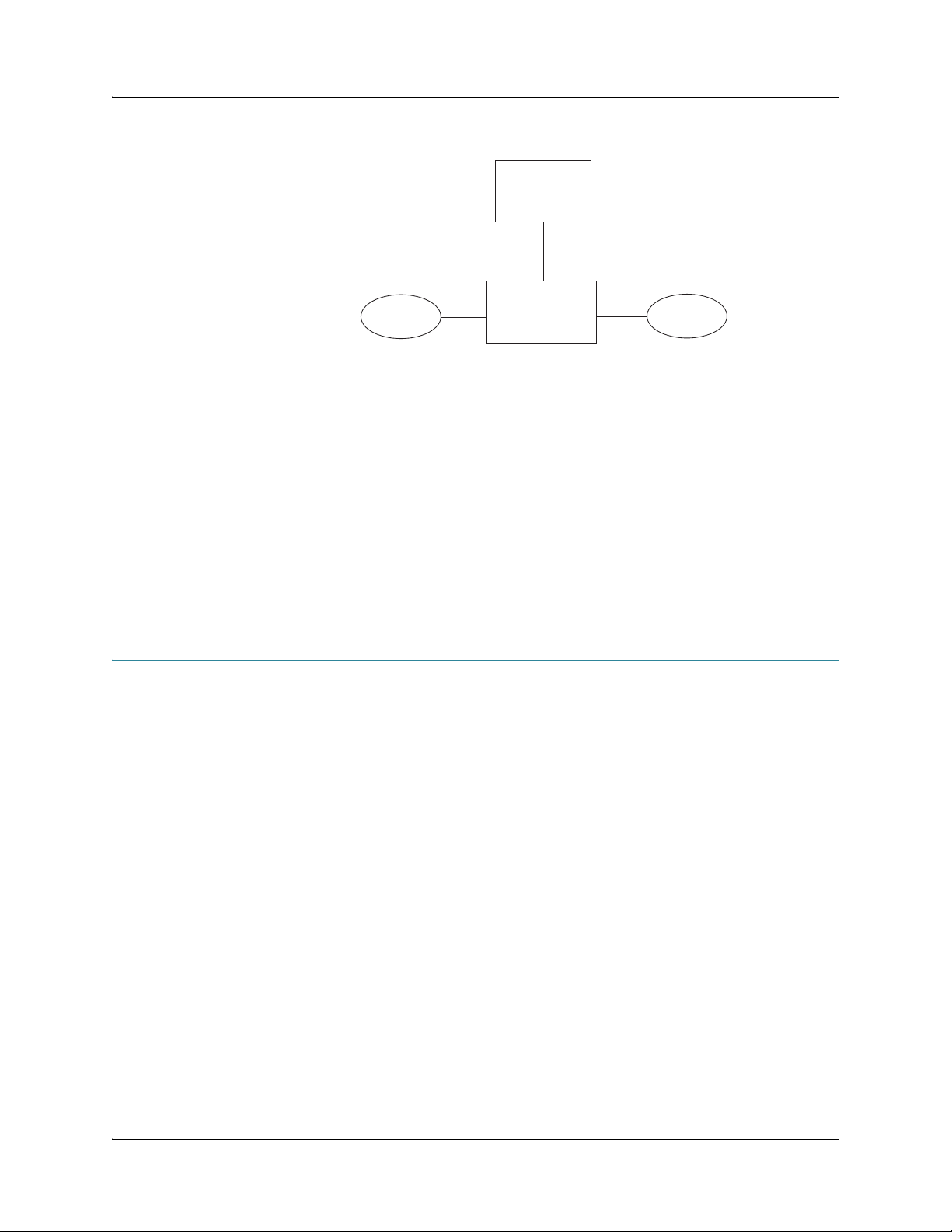
The gateway architecture consists of two parts:
z Packet processor—Performs route lookups, packet forwarding, and interworking functions for
pseudowire aggregations
z Host processor—Provides Layer 3 routing services and network management
Though there are two logical parts, physically they are packaged in a single integrated chip, using
an internal fabric to communicate with each other. The packet processor and the host processor
are realized using an off-the-shelf network processor. See Figure 1 on page 4 for an overview of the
gateway architecture.
Copyright © 2011, Juniper Networks, Inc. BX7000 Multi-Access Gateway Overview 3
Page 22
CHAPTER 1: BX7000 Multi-Access Gateway Overview
Figure 1: System Architecture of the BX7000 Multi-Access Gateway
Host Processor
Fabric
Packet Processor
The packet processor consists of four packet processing engines that perform Layer 2 and Layer 3
packet switching. It can process packets at an aggregate rate of 120 megabits per second. The
network processor promotes quick movement of packets through the gateway.
Host Processor
The host processor handles all routing protocol processes as well as the software processes that
control the gateway interfaces, the chassis components, the system management, and user
access to the gateway. These routing and software processes run on top of a kernel that interacts
with the packet processor. The host processor handles all packets that concern routing protocols,
freeing the packet processor to handle only packets that transit through the system. It also
provides different levels of system configuration and management functions, including
command-line interface (CLI), SNMP, and a NETCONF interface.
Hardware Components
This section provides the overview of the gateway’s hardware components:
z Gateway Chassis on page 4
z Front Panel on page 5
z LEDs on page 5
z T1/E1 Ports on page 6
z Ethernet Ports on page8
z Console Ports on page 11
z USB Host Port on page 12
z External Alarm Contacts on page 12
z Power Supplies on page 12
Packets in
Packet Processor
Packets out
g002900
Gateway Chassis
The chassis of the gateway is a rigid sheet metal structure that houses all the other gateway
components (see Figure 2 on page 5). The chassis measures 2.6 in. (6.7 cm) high, 17.51 in.
(44.47 cm) wide, and 9.44 in. (23.97 cm) deep (from front to the rear of the chassis) and installs in
a standard 19-in. equipment rack or in a standard enclosed cabinet.
4 Hardware Components Copyright © 2010, Juniper Networks, Inc.
Page 23
CHAPTER 1: BX7000 Multi-Access Gateway Overview
Air
Ground
Power supply
0 2 4 6 8 10 12 14
1 3 5 7 9 11 13 15
Table 1 on page 5 summarizes the physical specifications for the gateway chassis.
Table 1: Physical Specifications
Description Val ue
Chassis dimensions 2.6 in. (6.7 cm) high
17.51 in. (44.47 cm) wide
9.44 in. (23.97 cm) deep (from front to rear chassis)
Gateway weight DC model: 14.1 lb (6.4 Kg)
AC model: 13.22 lb (6.0 kg)
The gateway chassis can be mounted horizontally in a rack or vertically on a wall. All the power
receptacles, input/output ports, and expansion slots are located on the front panel of the gateway.
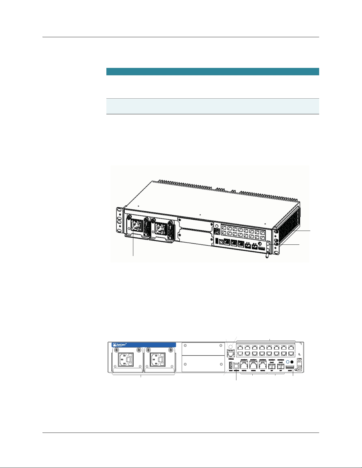
Figure 2: Front View of the BX7000 Multi-Access Gateway
Front Panel
LEDs
The front panel of the gateway has two power supplies, 16 T1/E1 ports, two console ports, one
universal serial bus (USB) host port, five Ethernet ports, one external alarm contact, LEDs that
allow you to view the status of the gateway and the ports, and two slots for expansion (see
Figure 3 on page 5).
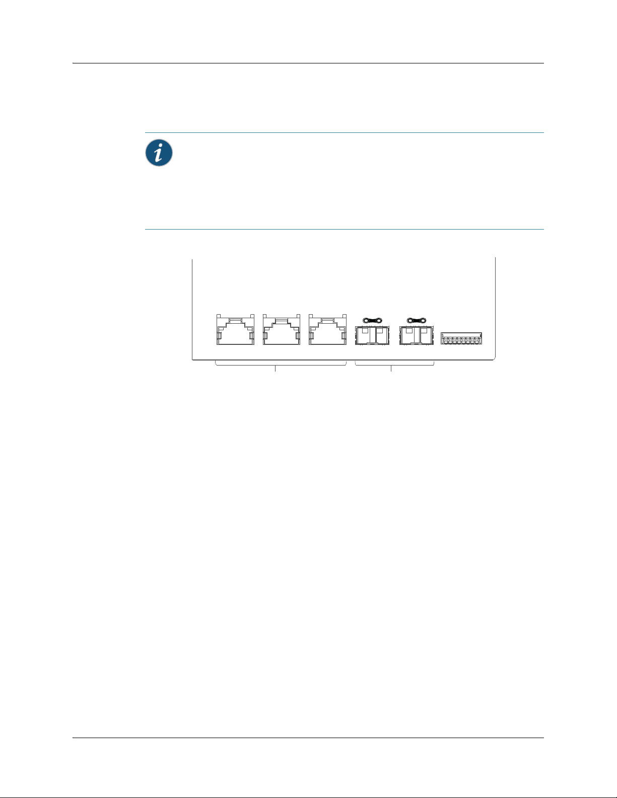
Figure 3: Front Panel of the BX7000 Multi-Access Gateway
Power supplies
BX 7000
CLOCK CARD
EXPANSION BAY
INTERFACE CARD
EXPANSION BAY
RJ-45 console port
USB host port
System LED
1 3 5 7 9 11 13 15
0 2 4 6 8 10 12 14
Copper ethernet ports
USB console port
T1/E1 Ports
Optical ports
External alarm
Grounding studs
Port LEDs
For more information on port LEDs, see “T1/E1 Ports” on page 6 and “Ethernet Ports” on page 8.
Hardware Components 5
g002902
Page 24

CHAPTER 1: BX7000 Multi-Access Gateway Overview
System LED
A tricolor system LED indicates the status of the power supplies, temperature, and conditions
based on chassis configuration such as LOS (loss of signal), Ethernet link down. A condition that
causes a change in the system LED indication also activates the corresponding alarm relay contact
on the front panel. Table 2 on page 6 describes the status of the system LED.
Table 2 : Syste m LE D
Shape Color State Description
Green
On steadily The gateway is functioning normally,
temperature and outputs are within
range, and no alarms are present
Ye l lo w
On steadily A non-critical or minor condition
requires monitoring—Possible causes
include one of the power supplies
removed from the gateway or high
temperature
Red
On steadily A critical condition that can cause the
gateway to stop functioning and
requires immediate attention—
Possible causes include component
removal or failure
Off
Gateway powered down or initializing
Synchronization Status LED on the Advanced Clocking Module
The advanced clocking module has a bicolor LED to indicate the synchronization status of the
clocks. Figure 4 on page 6 shows the LED of the advanced clocking module. If the LED is green, the
advanced clocking module is locked with an input source. If the LED is amber, the advanced
clocking module is currently not locked and is either in holdover mode or free-running mode.
Figure 4: LED in the Advanced Clocking Module
LED
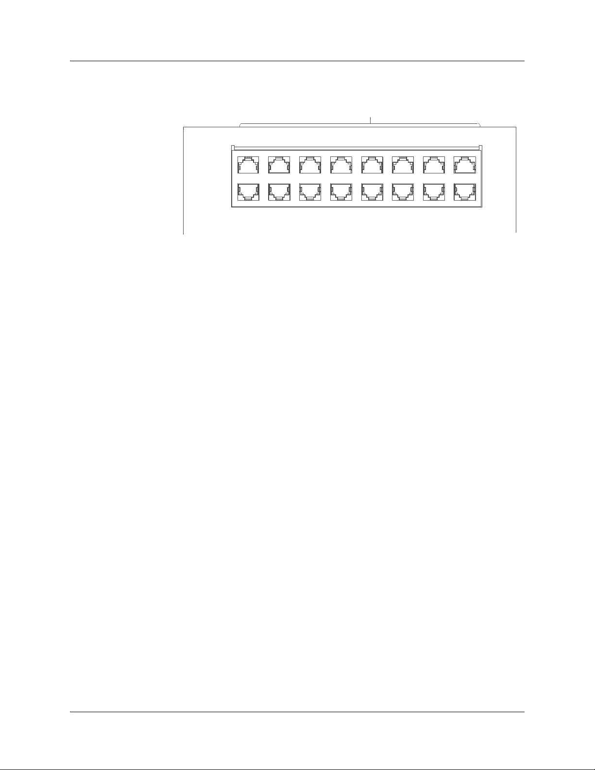
T1/E1 Ports
The T1/E1 ports provide connection to T1 or E1 network media types such as switches. They receive
incoming packets from the network and transmit outgoing packets to the network. Figure 5 on
page 6 shows the T1/E1 ports.
Figure 5: T1/E1 Ports
6 Hardware Components Copyright © 2010, Juniper Networks, Inc.
Page 25
CHAPTER 1: BX7000 Multi-Access Gateway Overview
T1/E1 ports
1 3 5 7 9 11 13 15
0 2 4 6 8 10 12 14
For information about the ports and connectors in the gateway, see Table 3 on page 8.
g002940
Hardware Components 7
Page 26

CHAPTER 1: BX7000 Multi-Access Gateway Overview
Table 3 : T 1/ E1 Po rt s
Description z 16 RJ-45 ports which can be configured either as T1 or E1
Hardware features z 16 T1/E1 ports supporting ATM, IMA, High-Level Data
Software features
Cables and connectors 16 RJ-45 connectors (one per port)—RJ-45 to RJ-45
LEDs Two rectangular single color LEDs for each T1/E1 port
Alarms, errors, and events z Alarm Indication Signal (AIS, YLW)
Link Control (HDLC)
z LEDs for status indication; for more information, see
LEDs
on page 8
z T1 framing: super frame (SF) and extended super frame
(ESF)
z E1 framing: G.703
z G.704—Channel Associated Signaling Multiframe
Format
z G.704-no-crc—Basic E1 framer format without CRC
z Per-port loop timing
z Integrated support for G.703 unframed mode and G.704
Channel Associated Signaling Multiframe Format; and
G.704-no-crc
z Encapsulations:
− High-Level Data Link Control (HDLC)
− Asynchronous Transfer Mode (ATM)
− Inverse Multiplexing over ATM (ATM-IMA)
− Point-to-Point Protocol (PPP)
− Transparent (Trans)
interface cable, Category 3
Link LED
z Green is lit in the following conditions:
− Admin-state is up and there is traffic through the port
− Admin-state is up and link is up
z Green is off in one of the following conditions:
− Error in traffic
− Link is down
− Admin-state down
Error LED
z Yellow is lit in the following error conditions:
− Admin-state is up and error in traffic
− Admin-state is up and link is down
z Yellow is off during admin-state down
z Excessive zeros (EXZ)
z Loss of frame (LOF), Loss of signal (LOS)
z Controlled Slip (CS)
Ethernet Ports
Five Ethernet ports are located in the lower right of the gateway (see Figure 6 on page 9). The
Ethernet ports can be used as either data ports or management ports.
z Three (10/100/1000Base-TX) copper Ethernet ports labeled ETHERNET 0, ETHERNET 1, and
ETHERNET 2.
z Two (1000 Base-X-SFP) fiber-optic Gigabit Ethernet ports with small form-factor pluggable
transceivers (SFPs) labeled ETHERNET 1 and ETHERNET 2.
8 Hardware Components Copyright © 2010, Juniper Networks, Inc.
Page 27
CHAPTER 1: BX7000 Multi-Access Gateway Overview
SFPs contain optical transceivers that support fiber-optic cable. Two rectangular LEDs on each
side of the copper Ethernet ports and two circular LEDs above each SFP show the link and the
status of ports. Table 4 on page 10 describes the functions of the Ethernet ports.
Note: For ETHERNET 1 and ETHERNET 2, you can connect both the copper Ethernet port and
the fiber-optic Ethernet port. However, only the copper port or the fiber-optic port can be active
at a time. If both ports are connected, the fiber-optic port will be active.
You can also use combination of these ports as follows:
z ETHERNET 1 of copper Ethernet port and ETHERNET 2 of fiber-optic Ethernet port
z ETHERNET 2 of copper Ethernet port and ETHERNET 1 of fiber-optic Ethernet port
Figure 6: Ethernet Ports
ETHERNET 0
COPPER
ETHERNET 1
COPPER
Copper Ethernet ports
ETHERNET 2
COPPER
ETHERNET 1
SFP
ETHERNET 2
SFP
ALARM
Fiber-optic Ethernet ports
g002908
Hardware Components 9
Page 28

CHAPTER 1: BX7000 Multi-Access Gateway Overview
Table 4: Ethernet Ports
Description z 3—10/100/1000 Base-TX copper Ethernet ports that
Hardware features z Auto-negotiation for copper ports
Software features
Cables and connectors z Copper (10/100/1000Base-TX): Unshielded twisted
LEDs
support Ethernet, Fast Ethernet, or Gigabit Ethernet
ports
z 2—1000 Base-X-SFP fiber-optic Gigabit Ethernet ports
z Cable crossover detection for copper ports
z High-performance throughput on each port at speeds
up to 1000 Mbps
z Full-duplex mode
z Maximum transmission units (MTUs) of up to 1500
bytes
z IP routing
z 802.1Q VLAN encapsulation support
z MPLS encapsulation support
pair (UTP), Category 5e or 6 cable, RJ-45 connector
z Use Category 5e UTP cables for copper Ethernet ports if
the installation environment requires radiated noise
immunity <= 3 V/m, conducted noise immunity <= 3 V
z Use Category 5e shielded twisted pair (STP) cables for
copper Ethernet ports if the installation environment
requires radiated noise immunity > 3 V/m, conducted
noise immunity > 3 V
z SFP: For more information on optical interface support,
see Table 5 on page 11
z Two rectangular LEDs on each side of the copper
Ethernet ports
z Two circular LEDs above each fiber-optic Ethernet port
LED activities for both the copper and the fiber-optic
Ethernet ports are as follows:
z Green is lit when
− Link is up
− Traffic passes through the port
z Green is off when
− Link is down
− No traffic
z Yellow is lit when
− Link is up
− Admin-state is enabled
z Yellow is off when
− Link is down
− Port not configured
10 Hardware Components Copyright © 2010, Juniper Networks, Inc.
Page 29
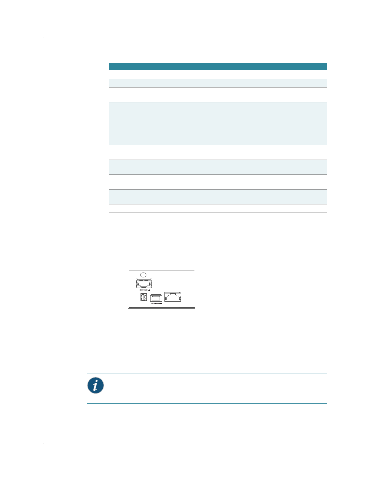
CHAPTER 1: BX7000 Multi-Access Gateway Overview
Table 5: Optical Interface Support for Gigabit Ethernet SFPs
Parame ter 1000Base-SX 1000Base-LX 1000Base-LH 1000Base-ZH
Optical interface Multimode Single-mode Single-mode Single-mode
Tra nsceiver type SFP SFP SFP SFP
Standard IEEE 802.3—2005 IEEE 802.3—2005 Multivendor
agreement
Maximum distance 62.5/125 MMF
cable: 2 to 220 m
50/125 MMF cable:
2 to 550 m
62.5/125 MMF
cable: 2 to 550 m
50/125 MMF cable:
2 to 550 m
9/125 SMF cable:
10 km
10/125 SMF cable:
0.002 to 5 km
Tra n sm i tt e r
wavelength
Average launch
power
Average receive
770 through
860 nm
–9.5 to less than 0
dBm
1270 through
1355 nm
Max –3 dBm to
min –11.5 dBm
1300 nm 1550 nm
0 to 3 dBm –2 to 3 dBm
Max 0 dBm Max –3 dBm –24 to –3 dBm –24 to –3 dBm
power
Recei ver
0dBm –3 dBm –3 dBm –3 dBm
saturation
Receiver sensitivity –17 dBm –19 dBm –24 dBm –24 dBm
Multivendor
agreement
9/125 SMF cable:
70 km
Console Ports
You can connect a console directly to the RJ-45 console port or to the USB 2.0 full-speed port of
the gateway. These two ports are labeled as CONSOLE (see Figure 7 on page 11).
Figure 7: Console Ports
RJ-45 console port
USB console port
z RJ-45 console port to connect the gateway to the serial port (RS-232 Port/COM port) of the PC
having console terminal session. An RS-232 serial cable with an RJ-45 connector is required.
z USB Type B console port to connect the gateway to the Type A USB port of the PC having
console terminal session. A standard USB cable with Type B connector is required.
Note: Although you can connect management devices to both console ports, only one console
port can be active at a time. If you connect to both the console ports, the USB console port will be
activated.
g002941
Hardware Components 11
Page 30
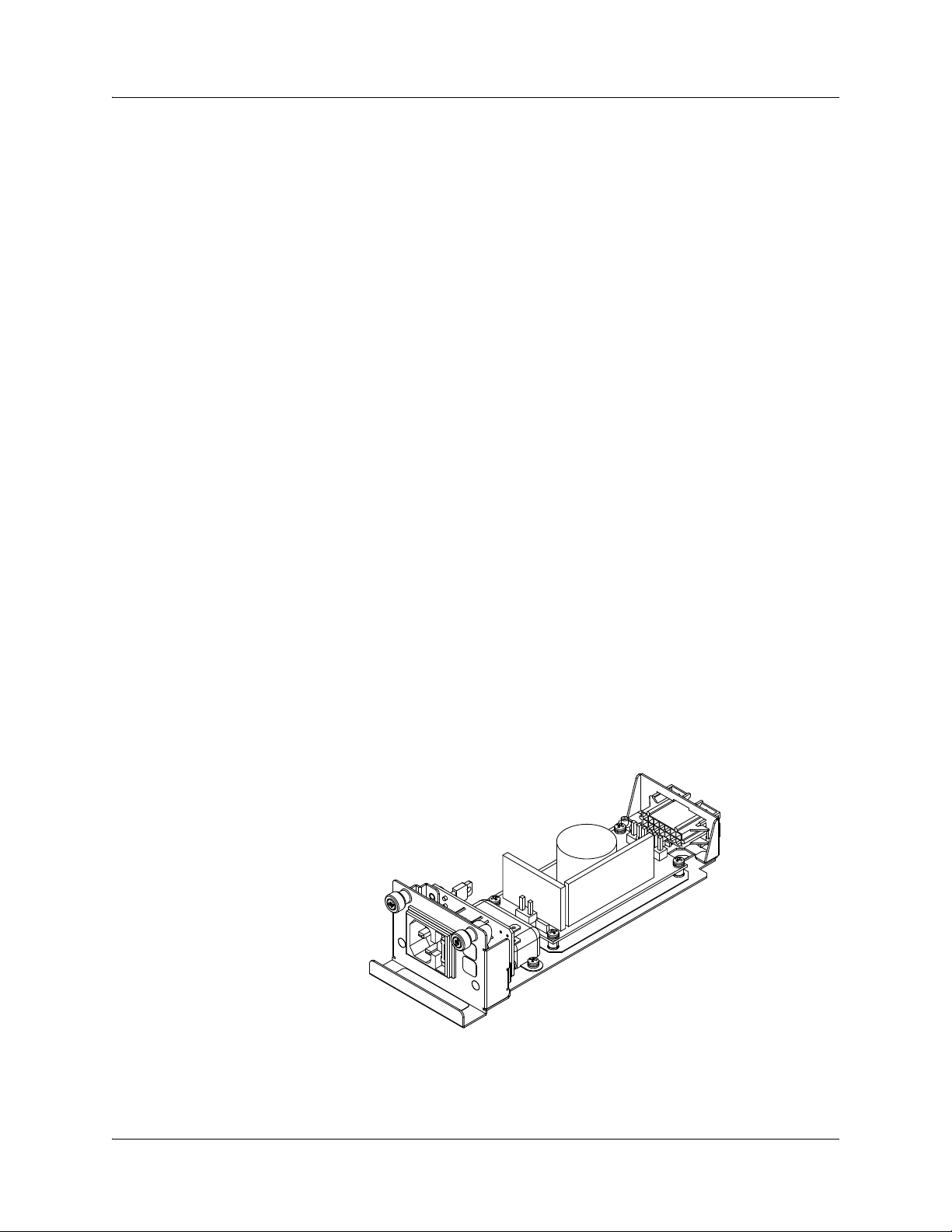
CHAPTER 1: BX7000 Multi-Access Gateway Overview
USB Host Port
Use the high-speed 2.0 USB host port, labeled FLASH, to connect a USB mass-storage device,
such as flash drive. The gateway uses this port to read configuration files during the initial startup.
This port supports a USB with Type A connector.
External Alarm Contacts
The gateway has four external alarm contacts (also known as potential free contacts) for
connecting the gateway to external alarm devices. The alarm relay contacts are located at the
lower right of the front panel. Whenever a system condition triggers an alarm, the alarm relay
contacts are activated which in turn activates the external alarm devices. Single core wires with a
gauge between 26-AWG and 24-AWG (0.5 to 0.8 mm2) are required to connect to external alarm
devices. For more information, see Connecting to an External Alarm Device on page 35.
The external alarm contact has eight pins that accept single core wire. Use the gauge of wire
appropriate for the external device that you are connecting. Each pair of pins adjacent to each
other, starting from the left, can be used to connect to one external alarm device. A total of four
devices may be connected to the wire-trap connector using the eight pins.
Power Supplies
The gateway contains one or two power supplies located on the left side of the front panel of the
chassis. The gateway uses either AC or DC power supplies. For both AC and DC power
configurations, the power supplies are hot-swappable when the gateway contains two power
supplies. If one power supply fails or is removed, the other power supply instantly takes the entire
electrical load without interrupting the operation of the gateway. For more information on AC and
DC power specifications, see “AC Power Specifications” on page 77 and “DC Power Specifications”
on page 78.
AC Power Supply
Each inlet requires a dedicated AC power feed. When both the power supplies are present, they
share the load almost equally within a fully populated gateway. Each power supply provides power
to all components in the gateway. Two AC power supplies provide full power redundancy. One
power supply provides full power to the gateway as long as it is operational. Figure 8 on page 12
shows the AC power supply.
Figure 8: AC Power Supply
DC Power Supply
Each DC power supply provides sufficient power to the fully populated gateway. The DC power
supplies can be either hardened or non-hardened. Two DC power supplies share power equally
within a gateway. Figure 9 on page 13 shows the DC power supply.
12 Hardware Components Copyright © 2010, Juniper Networks, Inc.
Page 31

CHAPTER 1: BX7000 Multi-Access Gateway Overview
Figure 9: DC Power Supply
Note: You can order a spare AC power supply unit or Hardened / Non-Hardened DC power suply
unit.
Fuse
The gateway has an electric fuse below both power supply slots. A time lag fuse of type 5 x 20 mm,
rated at 1.25A is used with the gateway.
Advanced Clocking Module
The advanced clocking module (see Figure 10 on page 14) is an optional field-replaceable
component that provides a synchronized clock signal to the gateway. The advanced clocking
module acquires the clock source and synchronizes communication over TDM interfaces in the
gateway. The advanced clocking module distributes a synchronized clock signal throughout the
gateway by locking onto a clock signal originating from an internal clock source or by connecting to
an external clock source.
The reference clock inputs can be T1/E1 line clocks, Ethernet recovered clocks, IEEE1588V2
recovered clocks, or xDSL NTU-R timing. Externally available reference clocks are BITS T1/E1 rate
clocks, 1 PPS, and 10 MHz. The two BNC connectors and one RJ-45 port on the front panel of the
advanced clocking module connect to external clock signal sources. The advanced clocking
module provides the synchronized output clocks from any one of the above reference inputs based
on the clock’s priority.
Note: The advanced clocking module is not hot-swappable. Removal or insertion of the
advanced clocking module in the gateway requires powering off the gateway.
There are eight methods to acquire and distribute the clock sources to the gateway. The advanced
clocking module can use input clocks from external reference clocks, or use recovered clocks from
within the gateway.
Internal sources include:
z Two (primary and secondary) T1/E1 line recovered clocks
z One Circuit Emulation Services (CES) recovered clock in T1 or E1 frequency rate
z Copper and fiber-optic Ethernet (2.5/25/125 MHz) line recovered clocks from mother board
Advanced Clocking Module 13
Page 32

CHAPTER 1: BX7000 Multi-Access Gateway Overview
An external source is derived from a signal coming into the gateway. These include:
z A building-integrated timing supply (BITS) clock source supplied to the advanced clocking
module using a T1 or E1 connection using a Category 3 cable with an RJ-45 connector
z One pulse per second (1PPS) input using BNC co-axial cable connected to the BNC connector
z 10 MHz, LVCMOS input using BNC co-axial cable connected to the BNC connector
IEEE 1588 PTP clock sources are rated by quality, or stratum level, where 1 represents the highest
possible quality of clocking. The advanced clocking module supports Stratum 3 level clock
synchronization.
All clock sources must conform to the following specifications:
z ITU-T G.823/G.824 for E1/T1 clock requirements
z PTP IEEE1588 support for slave mode
Note: The gateway supports only IEEE1588 slave mode.
You can configure the priority of the available clock sources from 1 through 7. The clock source with
priority one is locked and distributed to the TDM interfaces of the gateway. As the port providing
the clock source might fail, the priority for reference clock sources is programmable. For more
information about configuring the priority of a clock source, see the BXOS Configuration Guide.
Figure 10: Advanced Clocking Module
Location of Advanced Clocking Module in the Chassis
The Clock Card Expansion Bay accommodates the advanced clocking module. The advanced
clocking module is installed into the slot on the front of the gateway that is located above the
Interface Card Expansion Bay. shows the position of the advanced clocking module on the
chassis. For more information about configuring the advanced clocking module, see the BXOS
Configuration Guide.
14 Advanced Clocki ng Module Copyright © 2010, Juniper Networks, Inc.
Page 33

CHAPTER 1: BX7000 Multi-Access Gateway Overview
Figure 11: Position of Advanced Clocking Module on the Gateway
Clock Card
The advanced clocking module contains two BNC connectors and one RJ-45 connector on the
front to connect the external clock sources. Figure 12 on page 15 shows the front view of the
advanced clocking module.
Figure 12: Front View of Advanced Clocking Module
Advanced Clocking Module 15
Page 34

CHAPTER 1: BX7000 Multi-Access Gateway Overview
Table 6 on page 16 shows the features of the advanced clocking module.
Table 6: Advanced Clocking Module Features
Hardware features z Stratum 3 level clock synchronization
− Accuracy or adjust range: 4.6 x 10
− Pull in range: Must be capable of synchronizing to
clock with accuracy with ±4.6 x 10
− Stability: 3.7 x 10
− Time to first slip: 6 minutes (255 in 24 hrs)
z Integrated design to support synchronization accuracy
− ±50 ppb with OCXO
− ±280 ppb with TCXO
z Programmable priority for reference clock inputs
–7
–6
–6
Internal
− T1/E1 (1.544/2.048MHz) line clocks
− Ethernet recovered clocks
− IEEE1588V2 recovered clock
− xDSL NTU-R timing
External
− BITS T1/E1 (1.544/2.048 MHz) through RJ-45 (Cat 3)
− 10 MHz, LVCMOS through BNC connectors (50 ohms
TTL)
z Provides synchronized reference clock outputs
Internal
− T1/E1 (1.544/2.048 MHz) line clocks to mother board
and daughter board
− 25 MHz clock to Ethernet interface in mother board
and daughter board
− 8.192 MHz clock to mother board
− 19.44 MHz clock to mother board for differential
clock recovery
z Meets ITU-T G.823/G.824 for E1/T1 timing requirements
z PTP IEEE1588v2 support for slave mode
z Field-replaceable unit but not hot-swappable
z Board ID EEPROM and anti-counterfeit for secure
access
z Temperature monitoring
z Provided with heat sink arrangement for heat transfer
z LEDs for synchronization status (reference source lock
or unlock)
16 Advanced Clocking Module Copyright © 2010, Juniper Networks, Inc.
Page 35

Table 6: Advanced Clocking Module Features
Software features z Input sources:
− TDM
− Ethernet
− BITS
− 10 Mhz, LVCMOS
z Output sources:
− TDM
− Ethernet
z Any input source to any output source
z Switching of synchronous source
z Alarm and status retrieval using CLI commands
z ACS 9510 firmware upgraded through a BXOS
application.
z Manual control to switch to or from PTP source (PTP
highest priority)
z Polling of PTP alarm point to indicate when to switch to
or from PTP source
z PTP synchronization signal not monitored before
switching to it
z Alarm raised (polling) when no more wired sources can
be selected
CHAPTER 1: BX7000 Multi-Access Gateway Overview
Advanced Clocking Module 17
Page 36

CHAPTER 1: BX7000 Multi-Access Gateway Overview
18 Advanced Clocking Module Copyright © 2010, Juniper Networks, Inc.
Page 37

CHAPTER 2: Preparing the Site for Gateway Installation
CHAPTER 2
Preparing the Site for Gateway
Installation
This chapter describes how to prepare your site for installation of the BX7000 Multi-Access
Gateway. It contains the following sections:
z Site Preparation Checklist on page 19
z Wall Requirements on page 20
z Cabinet Requirements on page 20
z Rack Requirements on page 20
z Clearance Requirements for Airflow and Hardware Maintenance on page 21
Site Preparation Checklist
The location of the chassis, the layout of the mounting equipment, and security of your wiring room
are crucial for the operation of the gateway. The checklist in Table 10 on page 19 summarizes the
tasks you need to perform when preparing a site for gateway installation.
Table 10: Site Preparation Checklist
Item or Task For More Information Perfo rmed By Date
Verify that
environmental
conditions such as
temperature and
humidity do not exceed
gateway tolerance.
If mounting in a rack,
select the type of rack.
If mounting in a rack,
plan rack or cabinet
location, including
required space
clearances.
If a rack is used, secure
the rack to floor and
building structure.
Locate site for
connection of system
grounding.
“Gateway Environmental Specifications” on
page 75
“Rack Requirements” on page 20
“Cabinet Size and Clearance
Requirements” on page 21
“Rack Size and Strength” on page 20
“Clearance Requirements for Airflow and
Hardware Maintenance” on page 21
“Rack Requirements” on page 20
“Connecting the Grounding Wire” on
page 37
Copyright © 2011, Juniper Networks, Inc. Site Preparation Checklist 19
Page 38

CHAPTER 2: Preparing the Site for Gateway Installation
Item or Task For More Information Perfo rmed By Date
Measure distance
between external power
sources and gateway
installation site.
Acquire cables and
connectors.
Wall Requirements
The gateway can be installed on solid wall (for example, wood, plastic, concrete, or brick wall).
Ensure that the thickness of the wood and plastic wall on which the gateway can be installed is 1 in.
(2.54 cm). For more information on mounting the gateway on a wall, see “Wall-Mounted
Installation” on page 29.
Rack Requirements
The following sections describe the rack requirements:
z Rack Size and Strength on page 20
z Proper Rack Installation on page 20
“DC Power Specifications” on page78, “DC
Power Cable Specifications” on page 78,
“AC Power Specifications” on page77, and
“DC Power Cable Specifications” on
page 78
“BX7000 Multi-Access Gateway Overview”
on page 3
Rack Size and Strength
Proper Rack Installation
The gateway is designed for installation in a 19-in. (48.2 cm) rack as defined in Cabinets, Racks,
Panels, and Associated Equipment (document number EIA-310-D) published by the Electronics
Industry Association (EIA) (http://www.eia.org). You can install the gateway either in a 19-in. rack
or 23-in. rack.
The rack rails must be spaced wide enough to accommodate the dimensions of the gateway
chassis: 2.6 in. (6.7 cm) high, 9.44 in. (23.97 cm) deep, and 17.51 in. (44.47 cm) wide. The chassis
height of 2.6 in. (6.7 cm) is approximately 1.5 RU. The chassis comes with brackets for use with the
19-in. rack. Prepare the equipment racks by measuring and marking the space for each gateway
you plan to install.
Note: A separate installation kit is provided for 23-in. rack.
To confirm proper equipment rack installation, verify the following:
z Racks are installed and electrically grounded according to manufacturer instructions.
z Always secure the rack to the structure of the building. If your geographical area is subject to
earthquakes, bolt the rack to the floor. For maximum stability, secure the rack to the ceiling.
z Equipment rack installations comply with applicable local, state, and national codes.
Cabinet Requirements
The gateway can be installed in an enclosed cabinet with standard 19-in. rack rails. The following
sections describe cabinet requirements:
z Cabinet Size and Clearance Requirements on page 21
z Cabinet Airflow Requirements on page 21
20 Wall Requirements Copyright © 2010, Juniper Networks, Inc.
Page 39

Cabinet Size and Clearance Requirements
A standard 19-in. (48.26 cm) cabinet can accommodate the gateway. A single gateway requires
1.5 RU of space in the cabinet.
In a cabinet, the space required in front of the gateway to accommodate the cables and cords is
different depending on which ports you use. 2.16 in. (5.5 cm) space is required on the front of the
gateway when you use the fiber-optic cables to connect the fiber-optic ports. However if you plan
to use only copper Ethernet ports, 1.57 in. (4 cm) space is sufficient on the front of the gateway.
Cabinet Airflow Requirements
When you mount the gateway in a cabinet, you must ensure that ventilation through the cabinet is
sufficient to prevent overheating. Following is a list of requirements to consider when planning for
chassis cooling:
z Ensure that the cabinet allows the chassis hot exhaust air to exit from the cabinet without
recirculating into the gateway. An open cabinet (without a top or doors) that employs hot air
exhaust extraction from the top allows the best airflow through the chassis. If the cabinet
contains a top or doors, perforations in these elements assist with removing the hot air exhaust.
z Ensure that you have at least 20 mm clearance behind the gateway in the rear of the cabinet for
free airflow (see Figure 13 on page 21).
z Ensure that the gateway and all cables are dressed to minimize the blockage of airflow to and
from the chassis.
z Ensure that there is a minimum of 3 in. (7.6 cm) clearance between the inner side wall and the
gateway for free air flow when the gateway is installed in a cabinet.
CHAPTER 2: Preparing the Site for Gateway Installation
Clearance Requirements for Airflow and Hardware Maintenance
Plan the location of the gateway to provide space for connections to power, local communications,
and remote communications. Allow 2.16 in. (5.5 cm) in front of the gateway for routing the cables
when the gateway is installed in a cabinet.
At least 6 in. (15.2 cm) of clearance is required between each side of the gateway and any
heat-producing equipment.
Note: Leave the front side of the gateway open for connecting the cables.
Figure 13: Chassis Dimensions and Clearance Requirements
Clearance Requirements for Airflow and Hardware Maintenance 21
Page 40

CHAPTER 2: Preparing the Site for Gateway Installation
17.51”
(44.4 cm)
Rear of chassis
19”
(48.3 cm)
3”
(7.6 cm)
2.16” (5.5 cm)
Clearance required
for the cables
0.75” (2 cm)
Clearance required
for free airflow
Front of chassis
g002903
9.44”
(23.97 cm)
22 Clearance Requirements for Airflow and Hardware Maintenance Copyright © 2010, Juniper Networks, Inc.
Page 41

CHAPTER 3: Unpacking and Inspecting the Gateway
CHAPTER 3
Unpacking and Inspecting the Gateway
After you have prepared the installation site for the BX7000 Multi-Access Gateway, you can
unpack and install the gateway.
This chapter provides information about how to unpack the gateway from the box and how to
inspect the gateway components and other accessories.
This chapter contains the following sections:
z Unpacking the Gateway on page 23
z Inspecting the Gateway Components and Accessories on page 23
z If You Detect or Suspect Damage on page 25
To unpack the gateway, use a utility knife to cut the sealing tape on the shipping carton.
Unpacking the Gateway
The gateway is shipped in a cardboard box. The box measures 4.72 in. (12 cm) high, 14.17 in.
(36 cm) wide, and 22.83 in. (58 cm) deep. The box weighs 18.07 lb (8.2 Kg). A Getting Started
Guide is also included in each box.
To unpack the gateway:
1. Open the box cover with a knife.
2. Remove the chassis, shipping kit, and Getting Started Guide from the box.
3. Remove the ESD bag that covers the gateway.
4. Save the box cover and packing materials in case you need to move or ship the gateway later.
The packaging utilizes recyclable materials in the design and should be disposed of properly.
Recycle packaging according to your local, state, or country-specific laws and regulations.
Note: Wear gloves whenever you handle the gateway.
Inspecting the Gateway Components and Accessories
After you remove the components from the cardboard box:
z Confirm the parts in the box with the packing list included with the shipment.
z Inspect all external surfaces and external connectors for visible signs of damage.
z Inspect all parts shipped.
Copyright © 2011, Juniper Networks, Inc. Unpacking the Gateway 23
Page 42

CHAPTER 3: Unpacking and Inspecting the Gateway
z Document any damage noted during your inspection.
z Confirm that the gateway has the correct number and type of components for your ordered
configuration.
If any part is missing, contact a customer service representative.
The cardboard box contains the gateway and the following parts listed in Table 11 on page 24.
Table 11: Gateway Parts List
Part Quantity
19 in. mounting brackets 2
Product warranty 1
Getting Started Guide 1
Cable management brackets 2
EULA 1
You can order an installation kit to use during the installation of the gateway. Table 12 on page 24
lists the parts in the installation kit.
Table 12: Installation Kit Contents
Part Quantity
1 GB USB flash drive 1
USB console cable 1
RJ-45 Console/Ethernet cable 1
T1 loopback plug 1
Ethernet loopback plug 1
Wal l-Mounting Kit
23-inch Rack-Mounting Kit
You can order a wall-mounting kit. The parts of a wall-mounting kit are listed in Table 13 on
page 24.
Table 13: Parts of a Wall-Mounting Kit
Parts Quantity
Wall-moun ting bracket 1
Nylon plug 3
Wall-mounting screws (3.5 X 25 mm) 3
Note: The screws provided in the wall-mounting kit can be used for wooden or plastic wall. Use
Type 5 self tapping screws for other walls.
You can order a 23-inch rack-mounting kit. The parts of a 23-inch rack-mounting kit are listed in
Table 14 on page 24.
Table 14: Parts of a 23-inch Rack-Mounting Kit
Parts Quantity
23-in. mounting bracket assembly 2
M5 X 10 screws - (100 degree) Counter
sunk
4
24 Inspecting the Gateway Components and Accessor ies Copyrigh t © 2010, Juni per Networks, I nc.
Page 43

If You Detect or Suspect Damage
If you detect or suspect damage to any equipment:
z Contact the shipper responsible for delivery and formally report the damage.
z Contact Juniper Networks at 1-888-314-JTAC (from the United States, Canada, or Mexico) or
1-408-745-9500 (from elsewhere), or contact your sales representative if you have any
questions or concerns. See “Contacting Customer Support and Returning Hardware” on
page 109 for complete contact information.
CHAPTER 3: Unpacking and Inspecting the Gateway
If You Detect or Suspect D amage 25
Page 44

CHAPTER 3: Unpacking and Inspecting the Gateway
26 If You Detect or Suspect Damage Copyright © 2010, Juniper Networks, Inc.
Page 45

CHAPTER 4
Installing the Gateway
The BX7000 Multi-Access Gateway can be mounted on a wall or in a rack or cabinet. This chapter
describes how to install the gateway. It contains the following sections:
z Safety Requirements, Warnings, and Guidelines for Installing the Gateway on page 27
z Before you Begin on page 27
z Installing the Cable Management brackets on page 28
z Wall-Mounted Installation on page 29
z Rack-Mounted Installation on page 31
Safety Requirements, Warnings, and Guidelines for Installing the Gateway
CHAPTER 4: Installing the Gateway
Before you Begin
Warning: To avoid harm to yourself or the platform as you install and maintain the gateway,
follow the guidelines for working with and near electrical equipment as well as the safety
procedures for working with networking equipment.
z For a discussion on how to make the installation site a safe environment, see Preparing the Site
for Gateway Installation on page 19.
z For a list of safety warnings, see Safety and Regulatory Compliance Information on page 79 and
particularly Safety and Regulatory Compliance Information on page 79.
However, providing an exhaustive set of guidelines for working with electrical equipment is beyond
the scope of this guide.
Before installing the gateway, ensure the following:
z Verify that you have prepared the installation site as described in “Preparing the Site for
Gateway Installation” on page 19.
z Verify that the power supply is not connected to any power source.
z Correct the following hazardous conditions: moist or wet floors, leaks, and improper grounding.
z Check if you have the necessary tools and accessories to complete the installation.
Note: When mounting the gateway, ensure that it is within the reach of the power outlet.
Copyright © 2011, Juniper Networks, Inc. Safety Requirements, Warnings, and Guidelines for Installing the Gateway 27
Page 46

CHAPTER 4: Installing the Gateway
Installing the Cable Management brackets
You attach the cable management brackets vertically to each side of the chassis at the front. Use
the cable management brackets to keep the cables organized. Avoid bending optical cables
beyond the proper bend radius. The cable management bracket evenly distributes the weight of a
cable so that the cable is not subjected to undue stress at the connector.
To install the cable management bracket (see Figure 14 on page 28):
1. Attach an electrostatic discharge (ESD) grounding strap to your bare wrist and connect the
strap to one of the ESD points on the chassis. For more information about ESD, see
“Preventing Electrostatic Discharge Damage” on page 83.
2. Position the cable management bracket into the slots on the front of the chassis.
3. Use a number 1 Phillips screwdriver to tighten the M3 X 6 screws that are provided to secure
the cable management bracket to the chassis.
Figure 14 Installing the Cable Management Bracket
EXPANSION BAY
INTERFACE CARD
CLOCK CARD
EXPANSION BAY
g002938
28 Installing the Cable Management brackets Copyright © 2010, Juniper Networks, Inc.
Page 47

CHAPTER 4: Installing the Gateway
Warning: Install the cable management bracket only with mounting flanges pointed outward.
Wal l-Mounted I nstallatio n
Correct Method
Incorrect Method
Tools and Parts Required
This section describes the tools and parts required and the procedure for installing the gateway on
a wall.
Figure 15 on page 30 shows the wall-mounting bracket installed on a wall, and Figure 16 on
page 30 shows the gateway mounted on a wall. This section contains the following topics:
z Tools and Parts Required on page 29
z Installing the Gateway on a Wall on page 30
To install the gateway on a wall, you need the following tools:
z An appropriate screwdriver
z Three mounting screws (ST 3.5 X 25)—supplied with the wall-mounting kit
z Powered drill
z Three nylon plugs (5 X 25)—supplied with the wall-mounting kit
z Wall-mounting bracket—supplied with the wall-mounting kit
For more information about the tools and parts in the wall-mounting kit, see “Wall-Mounting Kit”
on page 24.
Wall-Mounted Installation 29
Page 48

CHAPTER 4: Installing the Gateway
Wal l-Mou nti ng Screws
The screws provided in the wall-mounting kit are 1 in. (2.54 cm) in length and can be inserted into
wood or plastic walls of thickness 1 in. or more. Table 15 on page 30 specifies the screws that you
can use for mounting the gateway on a wall.
Table 1 5: Wall -M ou nti ng S cr ews
Typ e of Wa ll Screw Size (d x l) Head Diameter Screw Type
Wood 3.5 X 25 mm 6.9 mm Self tapping
Plastic 3.5 X 25 mm 6.9 mm Self tapping
Note: For concrete or brick walls, use Type 5 self-tapping screws.
Installing the Gateway on a Wall
To install the gateway on a wall (see Figure 16):
1. Ensure that the wall is smooth, flat, dry, and sturdy.
2. Mark the points on the wall where you plan to drive the nail using the wall-mounting bracket
as a template.
3. Make holes in the marked points using a powered drill.
4. Insert the plug into the holes made.
5. Position the wall-mounting bracket and place the screws in the plugs. Use a screwdriver to
secure them at all three mounting points (see Figure 15 on page 30).
6. Hang the gateway on the two studs provided on the wall-mounting bracket (see Figure 16 on
page 30).
Figure 15: Installing the Wall-Mounting Bracket
Figure 16: Wall-Mounting the Gateway
g002904
30 Wall-Mounted Installation Copyright © 2010, Juniper Networks, Inc.
Page 49

Rack-Mounted Installation
CHAPTER 4: Installing the Gateway
g002906
The gateway can be installed in 19-in. and 23-in. racks using the appropriate brackets. The brackets
for 19-in. and 23-in. racks are shown in Figure 17 on page 31.
Figure 17: Rack-Mounting Brackets for the Gateway
Bracket for 19-inch Rack
This section describes the following:
z Installation Guidelines on page 32
z Tools and Parts Required on page 32
z Installing the Gateway in a Rack on page 32
Bracket for 23-inch Rack
Rack-Mounted Installation 31
Page 50

CHAPTER 4: Installing the Gateway
Installation Guidelines
Warning: Do not install more than three gateways adjacently in the same rack. This avoids
excessive pre-heating of the air flowing through the heatsinks of the upper units by the unit
directly below them.
Warning: Do not place a gateway between two gateways deeper than 23 cms. This avoids
formation of hot air traps around the rear heatsink of the gateway.
Tools and Parts Required
To install the gateway in a rack, you need the following tools:
z Screws—Use screws that are compatible with the equipment rack
z An appropriate screwdriver
Installing the Gateway in a Rack
To install the gateway in the rack (see Figure 18 on page 32):
1. Lift the gateway and position it in the rack.
2. Ensure that the holes of the mounting brackets align evenly with the holes of the equipment
rack on both sides.
3. Place the screws in the holes of the equipment rack, and secure them using an appropriate
screwdriver.
Figure 18: Rack-Mounting the Gateway
g002907
32 Rack-Mounted Installation Copyright © 2010, Juniper Networks, Inc.
Page 51

CHAPTER 5
Connecting the Gateway
This chapter describes how to cable the BX7000 Multi-Access Gateway. Before you cable the
gateway, ensure that you have completed all installation instructions identified in the previous
chapters.
This chapter contains the following sections:
z Before you Begin on page 33
z Cabling the Gateway to Management and Alarm Devices on page 33
Before you Begin
Before you start cabling the gateway, do the following tasks:
1. Familiarize yourself with all the ports provided in the gateway (see Figure 3), and ensure that
you have the cables and wires needed to complete each cabling procedure. For more
information about the ports, see “BX7000 Multi-Access Gateway Overview” on page 3.
2. Consider the distance from the connection points such as power, communication and the
place of installing the gateway when determining the size of cables and wires to be used. To
familiarize yourself with the electrical, environmental, and other guidelines and requirements,
see Safety Guidelines and Warnings on page 80.
3. Use the cable management brackets to keep the network interface cables untangled and
orderly to prevent cables from hindering access to other slots.
CHAPTER 5: Connecting the Gateway
Cabling the Gateway to Management and Alarm Devices
After you have installed the gateway, connect one or more external devices to the ports on the
front panel for management and service operations (see Figure 19 on page 34). Whenever you
connect the cables to the ports, make sure the connector clicks into the port. Direct access through
the RJ-45 console port enables you to monitor the system while it boots.
Copyright © 2011, Juniper Networks, Inc. Before you Begin 33
Page 52

CHAPTER 5: Connecting the Gateway
Figure 19: Management and Console Ports
RJ-45 console port
To connect external devices to the gateway ports, refer to the following sections:
z Connecting to a Console Terminal on page 34
z Connecting to an Ethernet Port on page 34
z Connecting to an External Alarm Device on page 35
z Connecting to T1/E1 Ports on page 36
z Connecting to the Advanced Clocking Module on page 36
z Connecting to the Advanced Clocking Module on page 36
Connecting to a Console Terminal
Use a console terminal, such as a laptop, a desktop, or any other auxiliary device to configure and
manage the gateway. You can connect the gateway to a console terminal directly using either the
RJ-45 console port or the USB console ports.
To Connect the Gateway Using the RJ-45 Console Port:
1. Plug the RJ-45 end of the crossover twisted-pair cable into the RJ-45 console port of the
gateway.
2. Connect the other end of the cable to the serial port of the console terminal or PC.
To Connect the Gateway Using the USB Console Port:
1. Plug the Type B end of the USB cable to the USB console port of the gateway.
2. Connect the Type A end of the USB cable to the USB port of the console terminal or PC.
CONSOLE
CONSOLE
USB console port
ETHERNET 0
COPPER
Copper Gigabit Ethernet ports
ETHERNET 1
COPPER
ETHERNET 2
COPPER
ETHERNET 1
SFP
Fiber-optic Gigabit Ethernet ports
ETHERNET 2
SFP
g002909
Connecting to an Ethernet Port
You can connect the gateway to external devices using any of the Ethernet ports.
z Connecting Gigabit Ethernet Fiber-Optic Cables on page 34
z Connecting Ethernet Copper Cables on page 35
Connecting Gigabit Ethernet Fiber-Optic Cables
For more information about fiber-optic transceivers, see “Optical Interface Support for Gigabit
Ethernet SFPs” on page 11.
To connect the fiber-optic cable to the SFP transceivers:
34 Cabling the Gateway to Management and Alarm Devices Copyright © 2010, Juniper Networks, Inc.
Page 53

CHAPTER 5: Connecting the Gateway
1. Remove the plug if the SFP transceiver is covered by a rubber safety plug.
Caution: Do not leave a fiber-optic transceiver uncovered except when inserting or removing
cable. The safety cap keeps the port clean and prevents accidental exposure to laser light.
2. Insert the cable connector into the SFP transceiver.
Warning: Do not look directly into a fiber-optic transceiver or into the ends of fiber-optic cables.
Fiber-optic transceivers and fiber-optic cables connected to a transceiver emit laser light that
can damage your eyes.
3. Arrange the cable in the cable management brackets to prevent it from dislodging or
developing stress points. Secure the cable so that it is not supporting its own weight as it
hangs to the floor. Place excess cable out of the way in a neatly coiled loop in the cable
management brackets. Placing fasteners on the loop helps to maintain its shape.
Caution: Avoid bending fiber-optic cable beyond its minimum bend radius. An arc smaller than a
few inches in diameter can damage the cable and cause problems that are difficult to diagnose.
Do not let fiber-optic cable hang free from the connector. Do not allow fastened loops of cable to
dangle, which stresses the cable at the fastening point.
Connecting Ethernet Copper Cables
For cable specifications, see Table 4 and “Ethernet Ports” on page8.
To connect the gateway to the Ethernet network:
1. Connect one end of an Ethernet cable with an RJ-45 connector (Figure 20 on page 35 shows
the connector) to one of the available copper Ethernet ports that are labeled from
ETHERNET 0 through ETHERNET 2.
2. Connect the other end of the cable to the appropriate network device.
Figure 20: Connector for Ethernet Cable
Connecting to an External Alarm Device
To connect the gateway to external alarm-reporting devices, connect wires to the relay contacts
on the front panel. A condition that triggers the red or yellow alarm LED on the front panel also
activates the corresponding alarm relay contact. The alarm relay contacts accept wire of any
gauge between 26-AWG and 24-AWG (0.4 to 0.5 mm2).
To connect an external device to the alarm relay contact:
1. Prepare the required length of single core wire with gauge of 26-AWG or 24-AWG.
2. Insert wires into the first two consecutive slots of the external alarm contact.
3. Connect the other end of the wires to the external device.
Repeat the procedure for attaching any other reporting device to the remaining pins of the external
alarm contact.
Cabling the Gateway to Management and Alarm Devices 35
Page 54

CHAPTER 5: Connecting the Gateway
Connecting to T1/E1 Ports
The gateway has 16 T1/E1 ports. These ports are connected to a switch or a router in the network.
Each T1/E1 port has an RJ-45 receptacle. Use the RJ-45-to-RJ-45 interface cable to connect the
port to a networking device.
To connect the RJ-45-to-RJ-45 interface cable to the T1/E1 ports:
1. Connect one RJ-45 end of the interface cable to the T1/E1 port on the front panel of the
gateway.
2. Connect the other RJ-45 end of the interface cable to the T1/E1 port of any networking device.
Connecting to the Advanced Clocking Module
You can use either of the two BNC connectors or the BITS interface on the advanced clocking
module.
Note: Ensure a cable of 3m or less in length is used for the 10 MHz and 1PPS connectors.
To connect the BNC co-axial cable to the advanced clocking module:
1. Connect one end of the BNC co-axial cable to either the 1PPS BNC connector or the 10 MHz
BNC connector on the advanced clocking module.
2. Connect the other end of the BNC co-axial cable to the 10 MHz or 1PPS source network
equipment.
3. Please ensure the 10MHz / 1PPS Sources are 50 ohms LVCMOS / LVTTL (3.3v) compatible.
To connect the interface cable to the advanced clocking module:
1. Connect the RJ-45 end of the interface cable to the BITS interface on the front of the
advanced clocking module.
2. Connect the other end of the interface cable to the T1/E1 port of any networking device.
36 Cabling the Gateway to Management and Alarm Devices Copyright © 2010, Juniper Networks, Inc.
Page 55

CHAPTER 6: Grounding and Powering the Gateway
CHAPTER 6
Grounding and Powering the Gateway
This chapter describes how to power on the BX7000 Multi-Access Gateway and verify if the
gateway has booted properly. This chapter contains the following sections:
z Tools and Parts Required on page 37
z Connecting the Grounding Wire on page 37
z Providing Power to the Gateway on page 39
z Powering On the Gateway on page 40
z Powering Off the Gateway on page 40
Tools and Parts Required
The tools and parts required to connect the grounding wire, AC power cords, and DC power cables
on the gateway are:
z Phillips (+) nutdriver, number 4
z An appropriate screwdriver
z 5/8” pitch twin hole grounding lug
z A standard ring terminal
z Ground wire—Use 14-AWG to10-AWG copper wire
z Power cord—For more information on the power cord, see “AC Power Cord Specifications” on
page 77
z Power cable—For more information on power cables, see “DC Power Cable Specifications” on
page 78
Connecting the Grounding Wire
Ground the gateway by connecting a grounding wire to earth ground and then connecting the other
end to one of the chassis grounding points using M4 nuts. The gateway has two grounding studs
located on the right side of the front panel to accommodate the lug. Washers and nuts are
attached to the grounding points and the studs are marked with an earth symbol. One grounding
screw of size M5 is provided on the left side in the rear of the gateway that can be used when the
gateway is mounted on the wall (see Figure 21 on page 37).
Warning: Always connect the grounding wires first (before connecting the power cords) and
disconnect them last when installing or servicing the gateway.
Figure 21: Grounding Points on the Gateway
Copyright © 2011, Juniper Networks, Inc. Tools and Parts Required 37
Page 56

CHAPTER 6: Grounding and Powering the Gateway
Grounding studs at the front
Grounding screw at the rear
grounding screw
g002939
grounding studs
To ground the gateway:
1. Verify that a licensed electrician has connected a grounding lug to the grounding cable.
2. Ensure that the grounding surface is clean and brought to a bright finish before grounding
connections are made.
3. Locate the two grounding studs on the right side of the front panel on the gateway.
4. Remove the M4 size nut and the locking washer from the grounding studs.
Note: Use a 14-AWG to10-AWG wire not exceeding 1 meter in length to connect the gateway with
the site safety ground.
5. Strip one end of the grounding wire. The amount of covering to be stripped varies depending
on the lug you attach to the wire.
6. Insert the stripped end of the grounding wire into the open end of the 5/8” pitch twin hole
grounding lug and crimp the grounding wire securely to the lug (see Figure 22 on page 39). Use
the lug manufacturer’s recommended crimping tool to ensure a proper crimp.
7. Attach the grounding lug to the threaded holes on the chassis and secure them first with
washers and then with M4 size nut.
8. Connect the other end of the grounding wire to a proper earth ground.
9. Verify that it does not touch or block access to the gateway and that it does not drape where
people could trip on it.
Note: Ensure that the wire is rust free and makes good contact when connected to the gateway.
38 Connecting the Grounding Wire Copyright © 2010, Juniper Networks, Inc.
Page 57

CHAPTER 6: Grounding and Powering the Gateway
Figure 22: Attaching Grounding Wire to the Grounding Lug
Wire
Providing Power to the Gateway
The gateway can be powered on by:
z Connecting Power to an AC-Powered Gateway on page 39
z Connecting Power to a DC-Powered Gateway on page 39
Connecting Power to an AC-Powered Gateway
After connecting the gateway to the ground, you can connect an AC power cord to the gateway. For
AC power cord specifications, see “AC Power Cord Specifications” on page 77.
To connect the AC power cords to the gateway:
1. Locate the power cord that has a plug appropriate for your geographical location; see “AC
Power Cord Specifications” on page 77.
2. Attach an electrostatic discharge (ESD) grounding strap to your bare wrist and connect the
strap to one of the ESD points on the chassis. For more information about ESD, see
“Preventing Electrostatic Discharge Damage” on page 83.
3. Insert the appliance coupler end of the power cord into the power supply receptacle in the
gateway.
4. Insert the power cord plug into an AC power source receptacle.
5. Repeat Steps 1 through 4 for the other power supply.
Grounding lug
g002905
Warning: Verify that the grounding wire and the power cord do not block access to gateway
components or drape where people could trip on them.
Connecting Power to a DC-Powered Gateway
You connect DC power to the gateway by attaching power cables from the DC power sources to
the terminal studs on the power supply.
Warning: Be sure the external power source is turned off before connecting power to the
gateway.
To connect the DC source power cables to the gateway:
1. Verify that the DC power cables are correctly labeled before making connections to the power
supply.
Providing Power to the Gateway 39
Page 58

CHAPTER 6: Grounding and Powering the Gateway
2. Attach an electrostatic discharge (ESD) grounding strap to your bare wrist and connect the
strap to one of the ESD points on the chassis. For more information about ESD, see
“Preventing Electrostatic Discharge Damage” on page 83.
Caution: You must ensure that power connections maintain the proper polarity. The power
source cables might be labeled (+) and (–) to indicate their polarity. There is no standard color
coding for DC power cables. The color coding used by the external DC power source at your site
determines the color coding for the leads on the power cables that attach to the terminal studs
on each power supply.
3. Remove the screws from the terminal studs.
4. Secure each power cable lug to the terminal studs.
a. Attach the negative wire lug to the negative (–) terminal stud.
b. Attach the positive wire lug to the positive (+) terminal stud.
5. Verify that the power cabling is correct, that the cables are not touching or blocking access to
the gateway and do not drape where people could trip on them.
6. Repeat Steps 1 through 4 for connecting the other power supply.
7. Connect the power cables to the power source.
Powering On the Gateway
To power on the gateway:
1. Verify that an external management device is connected to the console port on the gateway.
2. Turn on the power of the external management device.
3. Verify that the power supply is fully inserted in the chassis.
4. Verify that the source power cord is securely inserted into the appliance inlet.
5. Switch on the customer site circuit breakers to provide voltage to the power supply.
6. Monitor the startup process on the external management device to verify that the system has
Powering Off the Gateway
To power off the gateway:
1. Issue the request system reboot command on the external management device connected
cli@BX7000# request system reboot
Reboot the system ? (yes or no): yes
Save current configuration for next reboot? (yes or no):
For more information about connecting the console terminal, see “Connecting to a Console
Terminal” on page 34.
When the gateway is powered on successfully and diagnostic tests are complete, the system
LED is lit green, indicating that the gateway and power supplies are functioning normally. See
“System LED” on page 6.
booted properly.
to the gateway to temporarily suspend the system operation. Use the request system reboot
command to clear all committed and uncommitted commands.
A confirmation message is displayed. You can either save the configurations or discard the
configuration.
40 Powering On the Gateway Copyright © 2010, Juniper Networks, Inc.
Page 59

CHAPTER 6: Grounding and Powering the Gateway
a. To save the configuration, type yes.
b. To discard the configuration, type no.
Depending on the input, the gateway either reboots after saving the previous configurations or
reboots without saving. For more information about the command, see the BXOS CLI Users
Guide and Command Reference.
2. Follow your site instructions to turn off the power to the gateway.
Powering Off the Gateway 41
Page 60

CHAPTER 6: Grounding and Powering the Gateway
42 Powering Off the Gateway Copyright © 2010, Juniper Networks, Inc.
Page 61

CHAPTER 7: Accessing and Configuring the Gateway
CHAPTER 7
Accessing and Configuring the Gateway
This chapter describes how to access and configure the BX7000 Multi-Access Gateway.
This chapter contains the following sections:
z Console Port Setup on page 43
z Initial Setup on page 44
Console Port Setup
The console enables you to access and manage the gateway using the command-line interface
(CLI). You can configure the gateway either by using the RJ-45 console port or the USB console port.
You can access the console through a standard terminal application in the PC (Microsoft Windows,
Macintosh, or UNIX workstation).
You can use any terminal application to communicate with the gateway. The following settings are
required for the terminal emulation program:
z Baud rate: 9600
z Data bits: 8
z Parity: None
z Stop bits: 1
z Flow control: None
After you power on the gateway, your console is ready to communicate with the gateway. The
gateway performs the bootup process and displays the login prompt as follows:
BX7000 login:
1. You can log in to the system either as cli or as root at the login prompt. Then enter the
password.
2. If you log in as CLI user, the prompt appears as follows:
cli@BX7000>
3. Enter the configure command at operational mode.
cli@BX7000> configure
cli@BX7000#
The symbol # indicates that the gateway is in configuration mode.
4. If you log in as root, the prompt appears as follows:
root@BX7000#
Copyright © 2011, Juniper Networks, Inc. Console Port Setup 43
Page 62

CHAPTER 7: Accessing and Configu ring the Gateway
Initial Setup
After you deploy the gateway at the site, assign an IP address to the gateway. This section contains
the following topics:
z Assigning an IP Address on page 44
z SSH Setup on page 44
Assigning an IP Address
To assign a management IP address to the Ethernet port of the gateway, log in to the BX7000
console either through local or remote access. You can log in to the console through remote access
by means of a console switch.
After you assign an IP address to the Ethernet port, you can communicate remotely by running SSH
over an Ethernet network.
To configure the gateway IP address, include the family (inet | iso) address
statement at the [edit interface
[edit interface
set family inet address
SSH Setup
When you have configured an IP address for the system, you can run the SSH client from a host to
access the gateway through its configured port.
SSH enables remote systems to establish a secure connection with the
gateway. The gateway supports implementation of both the SSH server and the client. The SSH
server functionality enables remote hosts having the SSH client functionality to log on securely to
the gateway. The SSH client functionality enables the gateway to establish secure SSH sessions to
remote servers. The advantage of using SSH is that all the data exchanged is encrypted to prevent
intruders from accessing private information.
To access the gateway through a host:
1. Run SSH from a host on the same Ethernet network as the gateway.
2. Enter the IP address of the gateway to open the SSH session. The login prompt appears when
the SSH session to the gateway is established.
interface-name
address/destination prefix
interface-name
unit
logical-unit-number
unit
logical-unit-number
]
;
destination/prefix
] hierarchy level:
bx7000 login:
3. You can log in to the gateway either as CLI or root at the login prompt. Then enter the
password.
If you login as CLI, the prompt appears as:
cli@BX7000>
To enter configuration mode, enter the configure command:
cli@BX7000> configure
cli@BX7000#
If you log in as root, the prompt appears as:
root@BX7000#
44 Initial Setup Copyright © 2010, Juniper Networks, Inc.
Page 63

CHAPTER 7: Accessing and Configuring the Gateway
Caution: Do not change the IP address for the Ethernet interface that you are using to
communicate with the system. If you change the address, you will lose the SSH session.
Initial Setup 45
Page 64

CHAPTER 7: Accessing and Configu ring the Gateway
46 Initial Setup Copyright © 2010, Juniper Networks, Inc.
Page 65

PA RT 2
Hardware Maintenance,
Troubleshooting, and Replacement
Procedures
z Maintaining the Gateway on page 49
z Troubleshooting on page 53
z Replacing Hardware Components on page 59
:
Copyright © 2011, Juniper Networks, Inc. 47
Page 66

:
48 Copyright © 2010, Juniper Networks, Inc.
Page 67

CHAPTER 8
Maintaining the Gateway
This chapter describes how to maintain the hardware components installed in the BX7000
Multi-Access Gateway.
This chapter contains the following sections:
z Routine Maintenance Procedure on page 49
z Maintaining Cables on page 49
z Maintaining Power Supplies on page 50
z Maintaining the Advanced Clocking Module on page 50
Routine Maintenance Procedure
CHAPTER 8: Maintaining the Gateway
Maintaining Cables
Both sides of the gateway have air intake vents, which attract dust. For optimum performance of
the gateway, perform the following preventive maintenance procedures regularly:
Warning: Do not insert any metal object, such as a screwdriver, or place your hand into an open
slot when the gateway is powered on. Remove jewelry (including rings, necklaces, and watches)
before working on the equipment that is connected to power lines. These actions prevent electric
shock and serious burns.
z Inspect the installation site for moisture, loose wires or cables, and excessive dust. Make sure that
airflow is unobstructed around the gateway and into the air intake vents.
z Check the LEDs on the front panel for the status of the ports and the power supply of the
gateway. For more information on LEDs, see “BX7000 Multi-Access Gateway Overview” on
page 3.
z Periodically inspect the site to ensure that the grounding and the power cords connected to the
gateway are securely in place and that there is no moisture accumulating near the gateway.
To maintain cables:
z Use the cable management brackets to support cables and prevent cables from dislodging or
developing stress points.
z Place excess cable out of the way in the cable management brackets. Do not allow fastened
loops of cable to dangle from the connector or cable management bracket as this stresses the
cable at the fastening point. Put fasteners on the loops to help maintain their shape.
z Keep the cable connections clean and free of dust and other particles, which can cause drops in
the received power level. Always inspect cables and clean them if necessary before connecting
an interface.
The following guidelines apply specifically to fiber-optic cable:
Copyright © 2011, Juniper Networks, Inc. Routine Maintenance Procedure 49
Page 68

CHAPTER 8: Maintaining the Gateway
z When you unplug a fiber-optic cable from the gateway, always place a rubber safety plug over the
transceiver on the gateway and on the end of the cable.
z Anchor fiber-optic cable to avoid stress on the connectors. When connecting fiber-optic cable to
the gateway, ensure that it is not supporting its own weight as it hangs to the floor. Never let
fiber-optic cable hang free from the connector.
z Avoid bending fiber-optic cable beyond its bend radius. An arc smaller than a few inches can
damage the cable and cause problems that are difficult to diagnose.
z Frequent plugging and unplugging of fiber-optic cable into and out of optical instruments can
cause damage to the instruments that is expensive to repair. Instead, attach a short fiber
extension to the optical equipment. Any wear and tear due to frequent plugging and unplugging
is then absorbed by the short fiber extension, which is easy and inexpensive to replace.
z Keep fiber-optic cable connections clean. Small micro-deposits of oil and dust in the canal of the
transceiver or cable connector could cause loss of light, reducing signal power and possibly
causing intermittent problems with the optical connection.
z To clean the transceivers, use an appropriate fiber-cleaning device such as RIFOCS Fiber Optic
Adaptor Cleaning Wands (part number 946). Follow the directions for the cleaning kit you use.
z After you have cleaned the transceiver on the fiber-optic port, make sure that the connector tip of
the fiber-optic cable is clean. Use only an approved alcohol-free fiber-optic cable cleaning kit,
such as the Opptex Cletop-S Fiber Cleaner. Follow the directions for the cleaning kit you use.
Maintaining Power Supplies
To maintain the power supplies:
z Check the status of the power supplies by issuing the show chassis power command on the CLI.
The output is similar to the following:
cli@BX7000> show chassis power
Instance :0 Power_status : ON
Instance :1 Power_status : ON
z Make sure that the power cords and grounding wire are arranged so that they do not obstruct
access to other gateway components.
z Routinely check the system LED on the front panel. If the system LED is lit green, then the power
supply is functioning normally. For more information, see “System LED” on page 6.
z Power supply failure or removal triggers a yellow alarm. You can view the associated error
messages by issuing the following CLI command:
cli@BX7000> show chassis alarms
Maintaining the Advanced Clocking Module
After installing the advanced clocking module, use the following commands to troubleshoot the
advanced clocking module installation. For more information on configuring and operating the
advanced clocking module, see the BXOS Configuration Guide and BXOS CLI Users Guide and
Command Reference.
Use the following commands to maintain the advanced clocking module:
z Use the show input-clocks-status command to display the status information of the input clock
for the advanced clocking module, such as source and status, and the priority assigned to each
clock source.
cli@BX7000> show input-clocks-status
50 Maintaining Power Supplies Copyright © 2010, Juniper Networks, Inc.
Page 69

CHAPTER 8: Maintaining the Gateway
**************************************
Input clock Priority Validity
**************************************
line-tdm-primary 2 Invalid
line-tdm-secondary 3 Invalid
ces-rec-clock 4 Invalid
ethernet-rec-clock 5 Invalid
bits-clock 6 Valid
ext-10mhz 7 Invalid
z Use the show output-clocks-status command to display the status of the internal and external
output clocks for the advanced clocking module.
cli@BX7000> show output-clocks-status
Internal output clocks:
Ethrnet clock : enable
8 Khz Sync : enable
19.44 Diff clock : enable
T1/E1 TDM Clock : enable
External output clocks:
one-pps-clock : enable
z Use the show pll-status command to display the PLL status, current clock source, and the
priorities set for each clock source.
cli@BX7000> show pll-status
PLL Status: Phase Locked
Currently Selected Source: bits-clock
First Priority Validated Source: bits-clock
Second Priority Validated Source: none
Third Priority Validated Source: none
z Use the show clock-card-status command to check the status of the input and output clocks. As
shown in the sample output, the value corresponding to priority field indicates the priority set for
the input clock, the validity field indicates the status of the clock that is valid, and the interface
field indicates the interface from which the clock source is derived.
cli@BX7000> show clock-card-status
Input Clock Status:
*******************************************************************
Input clock Priority Validity Clock-type Interface
*******************************************************************
line-tdm-primary 2 Invalid wired t1-0/0/1
line-tdm-secondary 3 Invalid wired t1-0/0/2
ces-rec-clock 4 Invalid wired t1-0/0/3
ethernet-rec-clock 5 Invalid wired ge-1/0/1
bits-clock 6 Valid wired
ext-10mhz 7 Invalid wired
*******************************************************************
Revertive Mode : Disabled
Locked Status : Phase Locked
Clock Accuracy : 56149478475624359137401121013760.000000 PPM
Currently Selected Source : bits-clock
Highest Priority Validated Source : bits-clock
Maintaining the Advanced Clocking Module 51
Page 70

CHAPTER 8: Maintaining the Gateway
Second Highest Priority Validated Source : none
Third Highest Priority Validated Source : none
Output Clock Status :
Internal output clocks:
Ethrnet clock : enable
8 Khz Sync : enable
19.44 Diff clock : enable
T1/E1 TDM Clock : enable
External output clocks:
one-pps-clock : enable
52 Maintaining the Advanced Clocking Mo dule Copyright © 2010, Juniper Networks, Inc.
Page 71

CHAPTER 9
Troubleshooting
This chapter explains how you can troubleshoot a specific problem, such as abnormal LED activity
or no system power, when you power on the BX7000 Multi-Access Gateway. It contains the
following sections:
z Diagnosing Problems on page 53
z Understanding the Status LEDs to Troubleshoot on page 53
z Chassis and Interface Alarm Messages on page 54
z Troubleshooting Power Failures on page 55
z Troubleshooting High-Temperature Conditions on page 56
z Troubleshooting the Advanced Clocking Module on page 57
CHAPTER 9: Troubleshooting
Diagnosing Problems
When you first encounter a problem:
1. Make sure power connections are securely connected.
2. Observe the gateway LEDs carefully.
3. Make sure cable connections on the gateway are securely connected.
4. Ensure that the expansion cards and advanced clocking module are properly installed in the
chassis.
If a problem is beyond the scope of this chapter, see “Contacting Customer Support and Returning
Hardware” on page 109 for further instructions.
Note: Issuing the show version, show chassis hardware, and show chassis environment
commands is often a good step when trying to troubleshoot a problem.
Understanding the Status LEDs to Troubleshoot
LEDs show the immediate status of a port or a component and alert you about a problem
associated with them. Familiarize yourself with LED activities so that you can easily detect and
correct any problem related to them with minimal or no downtime.
LED Identification
LEDs on the gateway display the status of the following components.
z Port LEDs on page 54
z System LED on page 54
Copyright © 2011, Juniper Networks, Inc. Diagnosing Problems 53
Page 72

CHAPTER 9: Troubleshooting
Port LEDs
LEDs on the front panel of the gateway display system status and alert you to troubleshoot the
gateway. These LEDs include the following:
z T1/E1 port LEDs—Two LEDs (yellow and green) on top of each T1/E1 port indicate the status of
each T1/E1 port that is labeled from 0 through 15. At any one time, only one of the LEDs is lit. For
more information on LEDs, see “T1/E1 Ports” on page 6.
z Copper Ethernet port LEDs—Two LEDs (yellow and green) on the top of each copper Ethernet
port indicate the status of each Copper Ethernet port and are labeled as COPPER with
ETHERNET 0 through ETHERNET 2. For more information on LEDs, see “Ethernet Ports” on
page 8.
z Optical Ethernet port LEDs—Two LEDs (yellow and green) on top of each SFP indicate the status
of each SFP and are labeled as SFP with ETHERNET 1 and ETHERNET 2. For more information
on LEDs, see “Ethernet Ports” on page 8.
System LED
One system LED on the center of the front panel indicates the status of the gateway. Green
indicates that the gateway is functioning normally. Red indicates a critical condition that can cause
the gateway to stop functioning. Yellow indicates a non-critical or minor condition that requires
monitoring. For more information, see System LED on page 54.
Chassis and Interface Alarm Messages
When the gateway detects an alarm condition, it lights the red or the yellow alarm LED. To view a
more detailed description of the cause for the alarm, issue the show chassis alarms command:
cli@BX7000> show chassis alarms
There are two classes of alarms:
z Chassis alarms—Indicate a problem with a chassis component such as power supply and board
temperature, as described in Table 16 on page 54.
z Interface alarms—Indicate a problem with a specific network interface, as described in Table 17.
In Table 17 on page 55, the text in the column labeled CLI Message appears in the output from the
show chassis alarms command.
Table 16: Chassis Alarm Messages
Chassis
Componen t
Power
supplies
Te m p e r a t u r e The chassis
Alarm Condition Remedy Alarm Severity
A power supply has
been removed
A power supply has
failed
Only one power
supply is operating
temperature has
exceeded the
threshold (Default
threshold: 80° C).
Insert missing power supplies Red/yellow/ignore as you
configure
Replace failed power supply Red/yellow/ignore as you
configure
Insert or replace secondary
power supply
Check room temperature Red
Red/yellow/ignore as you
configure
54 Chassis and Interface Alarm Messages Copyright © 2010, Juniper Networks, Inc.
Page 73

Table 17: Interface Alarm Messages
CLI message
interface-name gige-x/x/x : Link Down
interface-name t1-x/x/x : Loss of Signal
interface-name t1-x/x/x : Alarm Indication Signal
interface-name t1-x/x/x : Loss of Frame
interface-name t1-x/x/x : Framer Yellow Alarm
interface-name t1-x/x/x : BEE
interface-name t1-x/x/x : Bipolar Violati on
interface-name t1-x/x/x : Excess Zero
interface-name t1-x/x/x : Line Code Violation
interface-name t1-x/x/x : CS
interface-name t1-x/x/x : RED
Troubleshooting Power Failures
To verify that a power supply is functioning normally:
z Check the system LED on the front panel. If the green LED is lit steadily, the power source is
providing power and the power supply is functioning normally.
z Issue the show chassis power command to check the status of installed power supplies. As
shown in the sample output, the value of Power_status indicates that the power supplies are
functioning normally.
CHAPTER 9: Troubleshooting
cli@BX7000> show chassis power
Power
Instance :0 Power_status : ON
Instance :1 Power_status : ON
If a power supply is not functioning normally, do the following to diagnose and correct the problem:
z If a red alarm occurs, issue the show chassis alarms command to determine the source of the
problem. The command displays the chassis and interface conditions that triggered the alarm.
The red alarm indicates a critical situation that needs immediate attention.
z If the system LED is off and no red alarm condition exists, check if the gateway is connected to a
power supply.
z Verify that the power cords from the power source to the gateway are not damaged. Replace the
cable if the insulation is cracked or broken.
z Connect the power supply to a different power source with a new power cable. If the system LED
still does not light, the power supply inlet in the gateway is the source of the problem. Replace the
power supply with a spare.
The gateway’s distributed power system is designed to consume low power. For specifications of
power consumption, see “System Specifications” on page 73. If you suspect a power problem, see
Table 18 on page 56.
Troubleshooting Power Failures 55
Page 74

CHAPTER 9: Troubleshooting
Table 18: Causes of Power Failures
Sympto m Possible problems Actions
Gateway does not power on z Gateway is not receiving power
z Power supply has
malfunctioned
z Power source cannot handle
the load
The following actions apply to all
possible problems:
1. Verify that all power
2. Verify that the power supply is
3. If the gateway still does not
connections are correct.
delivering the correct voltage,
current, and wattage to the
gateway.
operate, contact Juniper
Networks Customer Service.
Gateway reboots
Troubleshooting High-Temperature Conditions
The gateway has two temperature sensors for monitoring the temperature status in the gateway
chassis. If the gateway temperature exceeds the default maximum threshold limit of 80° C, a red
alarm is raised. The red alarm is cleared only if the temperature is reduced below the lower
threshold limit of 75° C.
To troubleshoot high-temperature conditions, follow these guidelines:
z Use the show chassis temperature command to display the temperature of the gateway. This
command displays the current temperature of the gateway from the two temperature sensors.
cli@BX7000> show chassis temperature
z Power supply has
malfunctioned
The following actions apply to all
possible problems:
1. Verify that the power
connections are properly
attached.
2. Verify that the gateway is
receiving power.
3. Confirm whether the LEDs are
lit.
4. If gateway does not reset,
contact Juniper Networks
Customer Service.
Instance : 0 Current Temperature(in Celcius) : 53
Instance : 1 Current Temperature(in Celcius) : 53
You can view the temperature of each chassis component by issuing the show chassis
environment command.
z Use the show chassis environment command to check the temperature and the status of the
power supply in the gateway. As shown in the sample output, the value Current Temperature
corresponding to the Tem p e r a t u r e field indicates the temperature of the gateway.
cli@BX7000> show chassis environment
Power
Instance :0 Power_status : ON
Instance :1 Power_status : ON
56 Troubleshooting High-Temperature Conditions Copyright © 2010, Juniper Networks, Inc.
Page 75

Temperature
Instance : 0 Current Temperature(in Celcius) : 49
Instance : 1 Current Temperature(in Celcius) : 50
z If the system LED on the front panel is lit red, use the show chassis alarms command to get
information about the source of an alarm condition and to get the status of the alarm.
cli@BX7000> show chassis alarms
11 alarms are currently active
Alarm time Class Description
2000-01-01 00:01:55 UTC Other e1-0/0/0 : RED
2000-01-01 00:01:55 UTC Other e1-0/0/0 : Loss of Frame
2000-01-01 00:02:00 UTC Other e1-0/0/1 : RED
2000-01-01 00:02:00 UTC Other e1-0/0/1 : Loss of Frame
2000-01-01 00:01:55 UTC Other e1-0/0/0 : Alarm Indication
Signal
2000-01-01 00:02:00 UTC Other e1-0/0/1 : Loss of Signal
2000-01-01 00:01:48 UTC Other gige-1/0/1 : Link Down
Troubleshooting the Advanced Clocking Module
If the card is not inserted properly in the Clock Card Expansion Bay slot, the POST displays the error
message “card is not detected.”
To troubleshoot:
1. Turn off the gateway.
2. Remove the card from its slot and reinstall the card into the slot.
3. After the gateway reinitializes, the card should be detected during POST.
4. If the POST again displays the message “card is not detected,” the gateway has detected a
hardware failure.
5. Contact the Juniper Networks Technical Assistance Center (JTAC) for instructions.
CHAPTER 9: Troubleshooting
Troubleshooting the Advanced Clocking Module 57
Page 76

CHAPTER 9: Troubleshooting
58 Troubleshooting the Advanced Clocking Module Copyright © 2010, Juniper Networks, Inc.
Page 77

CHAPTER 10: Replacing Hardware Components
CHAPTER 10
Replacing Hardware Components
This chapter provides information about how to replace the AC and DC power supply, an AC power
cord, a DC power cable, a fuse in the power supply, SFP transceivers, and alarm relay wires.
It contains the following sections:
z Field-Replaceable Units on page 59
z Tools and Parts Required on page 60
z Replacing an AC Power Supply on page 60
z Replacing a DC Power Supply on page 61
z Replacing an AC Power Cord on page 63
z Replacing a DC Power Cable on page 63
z Replacing the Fuse on page 64
z Replacing SFP Transceivers on page 65
z Replacing Alarm Relay Wires on page 67
z Replacing the Advanced Clocking Module on page 68
z Replacing the Advanced Clocking Module on page 68
z Replacing the Advanced Clocking Module on page 68
Field-Replaceable Units
Field-replaceable units (FRUs) are components that can be replaced at the customer site. The
gateway uses the following types of FRUs:
z Hot-swappable FRUs—You can remove and replace these components without powering down
the gateway.
z FRUs not hot-swappable —You cannot remove and replace these components without
powering down the gateway.
Table 19 on page 59 lists the FRUs for the gateway.
Table 19: Field-Replaceable Units
Hot-removable and hot-inser table FRUs FRUs not hot-swappable
Power supply Advanced Clocking Module
Copyright © 2011, Juniper Networks, Inc. Field-Replaceable Units 59
Page 78

CHAPTER 10: Replacing Hardware Components
Tools and Parts Required
To replace the hardware components, you need the tools and parts listed in Table 20 on page 60.
Table 20: Tools and Parts Required
Tool or part Componen t
Electrostatic discharge (ESD) grounding
wrist strap
Phillips (+) screwdriver, number 2 Power supplies, Advanced Clocking Module
Replacing an AC Power Supply
The power supplies are located at the front of the chassis. Each AC power supply weighs
approximately 0.99 lb (0.45 kg). For more information about AC power supply specifications, see
Table 25 on page 77.
To replace an AC power supply, perform the following procedures:
z Removing an AC Power Supply on page 60
z Installing an AC Power Supply on page 60
Removing an AC Power Supply
To remove an AC power supply (see Figure 23 on page 60):
1. Remove the power cord from the AC power source.
2. Attach an electrostatic discharge (ESD) grounding strap to your bare wrist and connect the
strap to the ESD point on the chassis. For more information about ESD, see “Preventing
Electrostatic Discharge Damage” on page 83.
3. Unplug the power cord from the AC receptacle on the power supply.
4. Loosen the thumbscrews at the top corners of the power supply.
5. Grasp the handle on the power supply faceplate and pull the power supply straight out of the
chassis.
All
Figure 23: Removing an AC Power Supply
Installing an AC Power Supply
To install an AC power supply (see Figure 24 on page 61):
1. Attach an electrostatic discharge (ESD) grounding strap to your bare wrist and connect the
strap to the ESD point on the chassis. For more information about ESD, see “Preventing
Electrostatic Discharge Damage” on page 83.
60 Tools and Parts Required Copyright © 2010, Juniper Networks, Inc.
Page 79

CHAPTER 10: Replacing Hardware Components
2. Slide the power supply straight into the chassis until the power supply is fully seated in the
chassis.
3. Tighten (but do not overtighten) the thumbscrews located at the top corners of the power
supply.
4. Insert one end of the AC power cord into the AC inlet on the power supply.
5. Insert the other end into the AC power source receptacle.
6. Verify that the system LED is lit steadily green, indicating that the power supply is functioning
normally.
7. Repeat Steps 2 through 4 to install the other AC power supply.
Note: If the LED is not lit steadily green, check whether the power supply is receiving power. If
necessary, repeat the procedure to install the power supply.
Figure 24: Installing an AC Power Supply
Replacing a DC Power Supply
The power supplies are located at the front of the chassis. Each DC power supply weighs
approximately 0.71 lb (0.32 kg). For more information about DC power supply specifications, see
Table 27 on page 78.
To replace a DC power supply, perform the following procedures:
z Removing a DC Power Supply on page 61
z Installing a DC Power Supply on page 62
Removing a DC Power Supply
To remove a DC power supply (see Figure 25 on page 62):
1. Switch off the dedicated customer site circuit breakers for the power supply being removed.
Follow your site's procedures for safety and ESD.
2. Ensure that the voltage across the DC power source cable leads is 0 V and that there is no
chance that the cables might become active during the removal process.
Replacing a DC Power Supply 61
Page 80

CHAPTER 10: Replacing Hardware Components
3. Attach an electrostatic discharge (ESD) grounding strap to your bare wrist and connect the
strap to the ESD point on the chassis. For more information about ESD, see “Preventing
Electrostatic Discharge Damage” on page 83.
4. Remove the screws from the terminal studs.
5. Remove the cable lugs from the terminal studs.
6. Loosen the thumbscrews at the top corners of the power supply.
7. Pull the power supply straight out of the chassis.
Figure 25: Removing a DC Power Supply
Installing a DC Power Supply
To install a DC power supply (see Figure 26 on page 63):
1. Ensure that the voltage across the DC power source cable leads is 0 V and that there is no
2. Attach an electrostatic discharge (ESD) grounding strap to your bare wrist and connect the
3. Slide the power supply straight into the chassis until the power supply is fully seated in the
4. Tighten (but do not overtighten) the thumbscrews located at the top corners of the power
5. Remove the screws from the terminal studs.
6. Secure each power cable lug to the terminal studs.
7. Verify that the power cabling is correct, that the cables are not touching or blocking access to
8. Switch on the dedicated customer site circuit breakers. Follow your site's procedures for
9. Verify that the system LED is lit steadily green, indicating that the power supply is functioning
10. Repeat Steps 3 through 8 to install the other power supply.
chance that the cable leads might become active during installation.
strap to the ESD point on the chassis. For more information about ESD, see “Preventing
Electrostatic Discharge Damage” on page 83.
chassis.
supply.
a. Attach the negative wire lug to the negative (–) terminal stud.
b. Attach the positive wire lug to the positive (+) terminal stud.
gateway, and that they do not drape where people could trip on them.
safety and ESD.
normally.
62 Replacing a DC Power Supply Copyright © 2010, Juniper Networks, Inc.
Page 81

Figure 26: Installing a DC Power Supply
Replacing an AC Power Cord
To replace an AC power cord, perform the following procedures:
z Disconnecting an AC Power Cord on page 63
z Connecting an AC Power Cord on page 63
CHAPTER 10: Replacing Hardware Components
Disconnecting an AC Power Cord
To disconnect the AC power cord:
1. Attach an electrostatic discharge (ESD) grounding strap to your bare wrist and connect the
strap to the ESD point on the chassis. For more information about ESD, see “Preventing
Electrostatic Discharge Damage” on page 83.
2. Unplug the power cord from the power source receptacle.
3. Unplug the power cord from the appliance inlet on the power supply.
Connecting an AC Power Cord
To connect the AC power cord:
1. Locate a replacement power cord with the type of plug appropriate for your geographical
location; see “AC Power Cord Specifications” on page 77.
2. Connect one end of the power cord to the power supply.
3. Insert the power cord plug into an external AC power source receptacle.
4. Ensure that the power cord does not block the access to gateway.
5. Verify that the system LED is lit green steadily indicating that the power cable is correctly
installed and the power supply is functioning normally.
6. Repeat Steps 2 and 3 to connect another AC power cord.
Replacing a DC Power Cable
To replace a power cable on a DC power supply, perform the following procedures:
z Removing a DC Power Cable on page 63
z Installing a DC Power Cable on page 64
Removing a DC Power Cable
To remove a power cable from a DC power supply:
Replacing an AC Power Cord 63
Page 82

CHAPTER 10: Replacing Hardware Components
1. Switch off the customer site circuit breakers. Follow your site's safety and ESD procedures.
2. Make sure that the voltage across the DC power source cable leads is 0 V and that there is no
chance that the cables might become active during the removal process.
3. Remove the power cable from the DC power source.
4. Attach an electrostatic discharge (ESD) grounding strap to your bare wrist and connect the
strap to the ESD point on the chassis. For more information about ESD, see “Preventing
Electrostatic Discharge Damage” on page 83.
5. Remove the screws from the terminal studs.
6. Remove the cable lug from the terminal studs.
7. Carefully move the power cable out of the way.
Installing a DC Power Cable
To install a replacement power cable for a DC power supply:
1. Locate a replacement power cable that meets the specifications defined in “DC Power Cable
Specifications” on page 78.
2. Verify that a licensed electrician has attached a cable lug to the replacement power cable.
3. Make sure that the voltage across the DC power source cable leads is 0 V and that there is no
chance that the cables might become active during the removal process.
4. Secure the power cable lug to the terminal studs.
5. Make sure the cable is not touching or in the way of the gateway, and that it does not drape
where people could trip on it.
6. Attach the power cable to the DC power source.
7. Switch on the customer site circuit breaker.
8. Verify that the system LED is lit green steadily indicating that the power cable is correctly
installed and the power supply is functioning normally.
9. Repeat Steps 2 through 6 to install another DC power cable.
Replacing the Fuse
Note: AC power supply assembly includes a second fuse in series with Neutral, which is not user
replaceable.
Note: Ensure that you use a time lag fuse of type 5 X 20 mm, rated at 1.25 A, 250v is used in the
gateway.
To replace the fuse (see Figure 27 on page 65):
1. Locate a replacement fuse appropriate for your power supply.
2. Unplug the power cord from the power supply receptacle for which the fuse has to be
replaced.
3. Unplug the other end of the power cord from the power source.
4. Loosen the fuse holder from the power supply and pull out the fuse from the holder.
64 Replacing the Fuse Copyright © 2010, Juniper Networks, Inc.
Page 83

CHAPTER 10: Replacing Hardware Components
5. Insert the new fuse into the inlet provided below the power supply and slide until the fuse
clicks into the place.
6. Insert one end of the power cord plug into the AC receptacle on the power supply and the
other end of the plug into a power source receptacle. Verify that the power cord does not
block access to gateway components or drape where people could trip on it.
When the power supply is plugged in successfully, the system LED is lit green indicating that the
power supply is functioning normally.
Caution: For continued protection against risk of fire, replace only with same type and rating of
fuse.
ATTENTION: Pour ne pas compromettre la protection contre les risques d'incendie, remplacer
par un fusible de même type et de memes caractéristiques nominales.
Figure 27: Replacing the Fuse
Replacing SFP Transceivers
The gateway has two small form-factor pluggable transceivers (SFPs) on the front panel. SFPs are
hot-insertable and hot-removable (see Figure 28 on page 65), but the fiber-optic ports no longer
receive or transmit data during replacement.
Warning: Do not insert any metal object, such as a screwdriver, or place your hand into an open
slot when the gateway is on. Remove jewelry (including rings, necklaces, and watches) before
working on equipment that is connected to power lines. These actions prevent electric shock and
serious burns.
Figure 28: SFP Connector
BX 7000
CLOCK CARD
EXPANSION BAY
INTERFACE CARD
EXPANSION BAY
Fuse
g002912
Connector
g002943
Replacing SFP Transceivers 65
Page 84

CHAPTER 10: Replacing Hardware Components
To replace an SFP transceiver, perform the following procedures:
z Removing an SFP on page 66
z Installing an SFP on page 66
Removing an SFP
To remove an SFP:
1. Have a replacement SFP ready and a rubber safety cap for the transceiver.
2. Label the cables connected to the SFP so that you can reconnect them correctly later.
Warning: Do not look directly into a fiber-optic transceiver or into the end of a fiber-optic cable.
Fiber-optic transceivers contain laser light sources that can damage your eyes.
3. Remove the cable connector plugged into the SFP.
4. Carefully drape the disconnected cable through the cable management bracket to prevent
the cable from developing stress points.
Caution: Avoid bending fiber-optic cable beyond its minimum bend radius. An arc smaller than a
few inches in diameter can damage the cable and cause problems that are difficult to diagnose.
Installing an SFP
5. Pull the ejector handle out from the SFP to unlock the SFP.
Caution: Make sure that you open the ejector handle completely until you hear it click. This
prevents damage to the SFP.
6. Grasp the SFP ejector handle and pull the SFP approximately 0.5 in. (1.3 cm) out of the SFP
slot.
7. Using your fingers, grasp the body of the SFP and pull it the rest of the way out of the SFP slot.
8. Place a rubber safety cap over the SFP.
To install an SFP (see Figure 38 on page 85):
1. Identify the slot where the SFP will be installed.
2. Verify that each SFP is covered by a rubber safety cap. If it is not, cover the SFP with a safety
cap.
3. Carefully align the SFP with the SFP slots. The connectors should face the SFP slot.
4. Slide the SFP until the SFP connector is seated in the SFP slot. If you are unable to fully insert
the SFP, make sure the connector is facing the right way.
Note: Make sure the connector clicks into the port.
5. Close the ejector handle of the SFP.
66 Replacing SFP Transceivers Copyright © 2010, Juniper Networks, Inc.
Page 85

CHAPTER 10: Replacing Hardware Components
6. Remove the rubber safety cap from the SFP and the end of the cable. Insert the cable into the
SFP.
7. Verify that the status LEDs above the SFP slot indicate that the fiber-optic port is functioning
normally. For more information on LEDs on the fiber-optic port, see “Ethernet Ports” on
page 8.
8. After replacing the SFPs and connecting the cables, issue the following command to ensure
that the interface is operational:
cli@BX7000>
Figure 29: Installing an SFP
Replacing Alarm Relay Wires
To replace the wires connected to an external alarm device (see Figure 30 on page 67):
1. Disconnect the existing wire at the external device.
2. Prepare the required length of replacement wire.
3. Using a screwdriver, push the body cover of the connector located on the top of the wire which
is to be disconnected from the wire-trap connector.
4. Remove the wire from the ALARM slot and release the body cover of the connector.
5. Push the replacement wire into the ALARM slot.
6. Connect the other end of the wire to the external device.
show interface
CONSOLE
FLASH
CONSOLE
interface-name
ETHERNET 0
COPPER
ETHERNET 1
COPPER
ETHERNET 2
COPPER
ETHERNET 1
SFP
ETHERNET 2
SFP
ALARM
g002913
Figure 30: Alarm Relay
Replacing Alarm Relay Wires 67
Page 86

CHAPTER 10: Replacing Hardware Components
For more information about external alarm contacts, see “External Alarm Contacts” on page 12.
Replacing the Advanced Clocking Module
The advanced clocking module is not hot-pluggable and is located between the power supplies
and flash port. It weighs approximately 1.014 lb (0.45 kg). To replace the advanced clocking
module, perform the following procedures:
z Removing the Advanced Clocking Module on page 68
z Installing the Advanced Clocking Module on page 69
External alarm contact
g002911
Removing the Advanced Clocking Module
To remove the advanced clocking module (see Figure 31 on page 68):
1. Attach an ESD wrist strap to your bare wrist and connect the wrist strap to one of the ESD
points on the chassis.
2. Switch off the dedicated customer site circuit breakers before disconnecting the power
supply.
3. Disconnect all the cables from the advanced clocking module.
4. Loosen the two M3 size captive screws on the front of the card.
5. Carefully slide the advanced clocking module out of the slot.
Figure 31: Removing the Advanced Clocking Module
68 Replacing the Advanced Clocking Module Copyright © 2010, Juniper Networks, Inc.
Page 87

Installing the Advanced Clocking Module
To install an advanced clocking module (see Figure 45 on page 92):
1. Attach an ESD wrist strap to your bare wrist and connect the wrist strap to one of the ESD
points on the chassis.
2. Ensure that the gateway is turned off.
3. Loosen the two M3 size captive screws on the blank faceplate on the front panel using a
number 2 Phillips screwdriver.
4. Remove the blank faceplate that covers the slot.
5. Remove the peel-off paper from the thermal pad of the advanced clocking module.
6. Hold the advanced clocking module horizontally, with the BITS interface and BNC connectors
facing towards you and the connectors facing the chassis slot.
7. Horizontally align the card with the guides at the right and left of the slot.
8. Gently push the card into the slot until the card is fully seated.
9. Tighten the captive screws on the front cover using the number 2 Phillips screwdriver.
10. Connect the cables to the BNC connector and BITS interface.
Caution: Do not force the card into the slot. Doing so may damage the card or the connector.
CHAPTER 10: Replacing Hardware Components
Figure 32: Installing the Advanced Clocking Module
Replacing the Advanced Clocking Module 69
Page 88

CHAPTER 10: Replacing Hardware Components
70 Replacing the Advanced Clocking Module Copyright © 2010, Juniper Networks, Inc.
Page 89

PA RT 3
Appendices
z System Specifications on page 73
z Safety and Regulatory Compliance Information on page 79
z Cabling Details on page 105
z Contacting Customer Support and Returning Hardware on page 109
z Declaration of Conformity on page 113
:
Copyright © 2011, Juniper Networks, Inc. 71
Page 90

:
72 Copyright © 2010, Juniper Networks, Inc.
Page 91

Appendix A
System Specifications
This appendix lists the system specifications, requirements, and certifications for the BX7000
Multi-Access Gateway.
z Physical Specifications on page 75
z Gateway Environmental Specifications on page 75
z Advanced Clocking Module Specifications on page 75
z Power Guidelines, Requirements, and Specifications on page 76
Table 21: General Specifications
Category Specification
Wei gh t
Chassis fully configured
Dimensions 17.5 x 2.6 x 9.4 in. (44.5 x 6.7 x 24 cm)
Environmental Requirements
Ambient operating temperature
:
Weights are approximate
DC model: 12.94 lb (5.87 kg)
AC model: 13.38 lb (6.07 kg)
NEBS GR-63-CORE compliant
NEBS GR-1089-CORE compliant
z DC Hardened: –40° to 158° F (–40° to 70° C)
z DC Non-hardened: 23° to 131° F (–5° to 55° C)
z AC: 23° to 131° F (–5° to 55° C)
95% maximum (noncondensing)
Ambient operating humidity
Ambient storage temperature
Ambient storage humidity
Heat dissipation 44 W, 150 BTU/hour maximum (for mother board
AC Input
Vol tag e
Maximum output power
Redundancy (input power)
DC Input
Vol tag e
Maximum output power
Copyright © 2010, Juniper Networks, Inc. 73
–40° to 70° C
5% to 95% (noncondensing)
and power supplies)
Operating range: 100 to 240 VAC nominal
Input line frequency: 50–60 Hz
50 W maximum
Two independent power supplies
24 to 60 VDC
50 W
Page 92

:
Category Specification
Space Requirements z 20 mm behind the gateway
z 3 in. between the inner side of the wall in a
cabinet and the gateway
z 6 in. between each side of the gateway and any
heat-producing equipment
z Do not block air vents on both sides of the
gateway
z 55 mm on the front of the gateway if fiber-optic
Ethernet ports are used
z 40 mm on the front of the gateway if copper
Ethernet ports are used
Airflow Air intake occurs on the left and right sides of the
gateway by natural convection
Safety Agency Certification
z CAN/CSA-C22.2 No. 60950-1-03 - UL 60950-1,
First Edition, Information Technology Equipment
- Safety - Part 1: General Requirements
z EN60825-1, Safety of Laser Products - Part 1:
Equipment Class, Requirements, and User's
Guide
z EN 60950-1:2006, Information Technology
Equipment - Safety - Part 1: General
Requirements
z IEC 60950-1 – CB Scheme
Telecommunications Certification
z T1 interfaces
− FCC ACTA TIA/EIA-IS-968 (Covers all types
of terminal equipment for direct connection
to the public switched network. Includes both
digital and analog interfaces.)
− Industry Canada, CS-03 (Covers all types of
terminal equipment for direct connection to
the public switched network. Includes both
digital and analog interfaces.)
z E1 Interface
− TBR 12/13
− ACA TS016
Electromagnetic Emissions Agency Certification
z AS/NZS (CISPR 22 Class A)
z EN55022 Class A
z VCCI (Voluntary Control Council for Interference
by Information Technology Equipment) Class A
z FCC CFR 47 Part 15 Class A
z EN-61000-3-2 Power Line Harmonics
74 Copyright © 2010, Juniper Networks, Inc.
Page 93

Physical Specifications
Table 22 on page 75 summarizes the physical specifications for the gateway chassis.
Table 22: Physical Specifications
Description Val ue
Chassis dimensions 2.6 in. (6.7 cm) high
Power supply Weight: AC power supply
Weight: DC model
Chassis with single power supply, fully configured
Chassis with dual power supply, fully configured
Weight: AC m odel
Chassis with single power supply, fully configured
Chassis with dual power supply, fully configured
Gateway Environmental Specifications
:
17.51 in. (44.47 cm) wide
9.44 in. (23.97 cm) deep
0.93 lb (0.42 kg)
Weight: DC power supply
0.71 lb (0.32 kg)
12.23 lb (5.54 kg)
12.94 lb (5.87 kg)
12.45lb (5.65kg)
13.38 lb (6.07 kg)
Table 23 on page 75 specifies the environmental specifications required for the gateway operation.
In addition, the site should be as dust-free as possible.
Table 23: Gateway Environmental Specifications
Description Val ue
Relative humidity Normal operation ensured in relative humidity
Temperature Normal operation ensured in the following
Seismic Designed to meet Telcordia Technologies Zone 4
Note: Install the gateway only in restricted or service areas, such as dedicated equipment rooms
and equipment closets, in accordance with Articles 110-16, 110-17, and 110-18 of the National
Electrical Code, ANSI/NFPA 70.
Advanced Clocking Module Specifications
Table 24 on page 75 lists the advanced clocking module specifications.
range of 5% to 95%, noncondensing
temperature range:
z DC Hardened: –40° to 158° F (–40° to 70° C)
z DC Non-hardened: 23° to 131° F (–5° to 55° C)
z AC: 23° to 131° F (–5° to 55° C)
earthquake requirements
Table 24: Advanced Clocking Module Specifications
Advanced Clocking Module Description
Dimensions (H X W X D) 150mm X 80mm X 26mm
Weight 1.014 l b (0.45 Kg)
Physical Specifications 75
Page 94

:
Advanced Clocking Module Description
Ports 2 BNC connectors, 1 RJ-45 connector
LED LED indicates the synchronization state of the clock
Cable and connector BNC co-axial cable with BNC connector and interface
Operating environment
Power consumption
TCXO Clock card
OCXO Clock Card
Power Guidelines, Requirements, and Specifications
z Site Electrical Wiring Guidelines on page 76
z Chassis Grounding Specifications on page 76
z AC Power Specifications on page 77
z AC Power Cord Specifications on page 77
z DC Power Specifications on page 78
z DC Power Cable Specifications on page 78
cable
z Storage temperature: –40°C to 70°C
z Operating temperature: –40°C to 70°C
z Humidity: 95% max.
z 6.82 W
z 10.2 W during start up
7.8 9 W a mbient @ 25°C
Site Electrical Wiring Guidelines
When planning the electrical wiring at your site, consider the factors discussed in the following
sections:
Distance Limitations for Signaling
Improperly installed wires can emit radio interference. In addition, the potential for damage from
lightning strikes increases if wires exceed recommended distances or if wires pass between
buildings. The electromagnetic pulse (EMP) caused by lightning can damage unshielded
conductors and destroy electronic devices. If your site has previously experienced such problems,
you might want to consult experts in electrical surge suppression and shielding.
Radio Frequency Interference
You can reduce or eliminate the emission of radio frequency interference (RFI) from your site wiring
by using twisted-pair cable with a good distribution of grounding conductors. If you must exceed
the recommended distances, use a high-quality twisted-pair cable with one ground conductor for
each data signal when applicable.
Electromagnetic Compatibility
If your site is susceptible to problems with electromagnetic compatibility (EMC), particularly from
lightning or radio transmitters, you might want to seek expert advice. Strong sources of
electromagnetic interference (EMI) can destroy the signal drivers and receivers in the gateway and
conduct power surges over the lines into the equipment, resulting in an electrical hazard. It is
particularly important to provide a properly grounded and shielded environment and to use
electrical surge-suppression devices.
Chassis Grounding Specifications
To meet safety and electromagnetic interference (EMI) requirements and to ensure proper
operation, the gateway must be adequately grounded before power is connected. For grounding
the gateway, use a 14-AWG to 10-AWG wire whose length depends on the location where the
gateway will be mounted. Two grounding studs are provided on the right side of the front panel for
connecting the gateway to earth ground. One grounding screw is provided on the left side in the
rear of the gateway for connecting the gateway to the earth ground when it is mounted on the wall.
76 Power Guidelines, Requirements, and Specifications Copyright © 2010, Juniper Networks, Inc.
Page 95

AC Power Specifications
AC Power Supply Electrical Specifications
Table 25 on page 77 lists the AC power supply electrical specifications.
Table 25: AC Power Supply Electrical Specifications
Item Description
Maximum output power for each power supply 50 W
AC input voltage Operating range: 100 to 240 VAC (nominal)
Maximum input current 1.25 A
AC input frequency 50–60 Hz (nominal)
AC Power Cord Specifications
Each AC power supply has a dedicated AC power feed. Use an AC power cord of voltage rating 250
V and current rating of at least three amperes. The appliance coupler at the female end of the cord
inserts into the appliance inlet on the faceplate of the AC power supply. The coupler is type C13 as
described by International Electrotechnical Commission (IEC) standard 60320. The plug at the
male end of the power cord fits into the power source receptacle that is standard for your
geographical location.
Table 26 on page 77 provides AC power cord specifications and Figure 33 on page 77 depicts the
plug types for AC power cord provided for each country.
:
Table 26: AC Power Cord Specifications
Country Electrical Specification Plug Type
Australia 240 VAC, 50 Hz AC SAA/3
Europe (except Italy and
United Kingdom)
Italy 230 VAC, 50 Hz AC CEI 23-16
Japan 110 VAC, 50 or 60 Hz AC JIS 8303
North America 120 VAC, 60 Hz AC NEMA 5-15P
United Kingdom 240 VAC, 50 Hz AC BS1363
220 or 230 VAC, 50 Hz AC CEE 7/7
Figure 33: AC Plug Types
Australia
Europe
Italy
Japan
North America
UK
g002910
For information about the AC power supply, see “AC Power Supply” on page 12. For instructions
on connecting the power cord and grounding cable during initial installation, see “Connecting the
Grounding Wire”
on page 37 and “Providing Power to the Gateway” on page 39.
Power Guidelines, Requirements, and Specifications 77
Page 96

:
DC Power Specifications
DC Power Supply Electrical Specifications
Table 27 on page 78 lists the DC power supply electrical specifications.
Table 27: DC Power Supply Electrical Specifications
Item Description
Maximum output power for each power supply 50 W
DC input voltage 24V to 60V DC
Maximum DC output voltage
Maximum DC output current 4.58A
Temperature range -40°C - 70°C
DC Power Cable Specifications
Use a DC power cable of voltage rating better than 100 V and current rating of at least 10 amperes.
You can use a spade lug of size 4 to attach the DC power cable to the terminal stud. Table 28 on
page 78 summarizes the specifications for the power cables, which you must supply.
Table 28: DC Power Cable Specifications
Cable Type Spec ification
Power 14-AWG wire
12V
78 Power Guidelines, Requirements, and Specifications Copyright © 2010, Juniper Networks, Inc.
Page 97

Appendix B
Safety and Regulatory Compliance
Information
To install and use the gateway safely, follow proper safety procedures. This appendix discusses
the following safety and regulatory compliance information:
z Definition of Safety Warning Levels on page79
z Safety Guidelines and Warnings on page 80
z Agency Approvals and Compliance on page 98
z Cabling Recommendations on page 100
z Hardware Compliance on page 101
:
Definition of Safety Warning Levels
Note: You might find this information helpful in a particular situation, or might otherwise overlook
it.
Caution: You need to observe the specified guidelines to avoid minor injury or discomfort to you,
or severe damage to the gateway.
Warning: This symbol means danger. You are in a situation that could cause physical injury.
Before you work on any equipment, be aware of the hazards involved with electrical circuitry and
be familiar with standard practices for preventing accidents.
Waarschuwing Dit waarschuwingssymbool betekent gevaar. U verkeert in een situatie die
lichamelijk letsel kan veroorzaken. Voordat u aan enige apparatuur gaat werken, dient u zich
bewust te zijn van de bij elektrische schakelingen betrokken risico's en dient u op de hoogte te zijn
van standaard maatregelen om ongelukken te voorkomen.
Copyright © 2010, Juniper Networks, Inc. Definition of Safety Warning Levels 79
Page 98

:
Var oi t us Tämä varoitusmerkki merkitsee vaaraa. Olet tilanteessa, joka voi johtaa
ruumiinvammaan. Ennen kuin työskentelet minkään laitteiston parissa, ota selvää
sähkökytkentöihin liittyvistä vaaroista ja tavanomaisista onnettomuuksien ehkäisykeinoista.
Attention Ce symbole d'avertissement indique un danger. Vous vous trouvez dans une situation
pouvant causer des blessures ou des dommages corporels. Avant de travailler sur un
équipement, soyez conscient des dangers posés par les circuits électriques et familiarisez-vous
avec les procédures couramment utilisées pour éviter les accidents.
War nu ng Dieses Warnsymbol bedeutet Gefahr. Sie befinden sich in einer Situation, die zu einer
Körperverletzung führen könnte. Bevor Sie mit der Arbeit an irgendeinem Gerät beginnen, seien
Sie sich der mit elektrischen Stromkreisen verbundenen Gefahren und der Standardpraktiken zur
Vermeidung von Unfällen bewußt.
Avvertenza Questo simbolo di avvertenza indica un pericolo. La situazione potrebbe causare
infortuni alle persone. Prima di lavorare su qualsiasi apparecchiatura, occorre conoscere i pericoli
relativi ai circuiti elettrici ed essere al corrente delle pratiche standard per la prevenzione di
incidenti.
Advarsel Dette varselsymbolet betyr fare. Du befinner deg i en situasjon som kan føre til
personskade. Før du utfører arbeid på utstyr, må du vare oppmerksom på de faremomentene
som elektriske kretser innebærer, samt gjøre deg kjent med vanlig praksis når det gjelder å unngå
ulykker.
Aviso Este símbolo de aviso indica perigo. Encontra-se numa situação que lhe poderá causar
danos físicos. Antes de começar a trabalhar com qualquer equipamento, familiarize-se com os
perigos relacionados com circuitos eléctricos, e com quaisquer práticas comuns que possam
prevenir possíveis acidentes.
¡Atención! Este símbolo de aviso significa peligro. Existe riesgo para su integridad física. Antes de
manipular cualquier equipo, considerar los riesgos que entraña la corriente eléctrica y
familiarizarse con los procedimientos estándar de prevención de accidentes.
Var n in g! Denna varningssymbol signalerar fara. Du befinner dig i en situation som kan leda till
personskada. Innan du utför arbete på någon utrustning måste du vara medveten om farorna
med elkretsar och känna till vanligt förfarande för att förebygga skador.
Warning: This symbol means exposure to laser radiation.
Safety Guidelines and Warnings
This section lists safety guidelines and warnings for installing, operating, and maintaining the
gateway:
z General Safety Guidelines and Warnings on page 80
z Fire Safety Requirements on page 84
z Installation Safety Guidelines and Warnings on page 84
z Laser and LED Safety Guidelines and Warnings on page 86
z Maintenance and Operational Safety Guidelines and Warnings on page 88
z Electrical Safety Guidelines and Warnings on page 92
General Safety Guidelines and Warnings
The following guidelines help ensure your safety and protect the gateway from damage. These
guidelines might not address all potentially hazardous situations in your working environment, so
be alert and exercise good judgment at all times.
80 Safety Guidelines and Warnings Copyright © 2010, Juniper Networks, Inc.
Page 99

z Perform only the procedures explicitly described in this manual. Make sure that only authorized
service personnel perform other system services.
z Keep the area around the chassis clear and free from dust before, during, and after installation.
z Keep tools away from areas where people could trip over them while walking.
z Do not wear loose clothing or jewelry, such as rings, bracelets, or chains, which could get caught
in the chassis.
z Wear safety glasses if you are working under any conditions that could be hazardous to your
eyes.
z Do not perform any actions that create a potential hazard to people or make the equipment
unsafe.
z Never attempt to lift an object that is too heavy for one person to handle.
z Never install or manipulate wiring during electrical storms.
z Operate the gateway only when it is properly grounded.
z Replace fuses only with fuses of the same type and rating.
Exercise the following guidelines to prevent electric shock, fire, and damage to the gateway:
z Do not open or remove chassis covers or sheet metal parts unless instructions are provided in
this manual.
z Do not push or force any objects through any opening in the chassis frame.
z Avoid spilling liquid onto the gateway chassis or onto any gateway component.
z Avoid touching uninsulated electrical wires or terminals that have not been disconnected from
their power source.
In addition, observe the following warnings and guidelines:
:
z Qualified Personnel Warning on page 82
z Restricted Access Area Warning on page 83
z Preventing Electrostatic Discharge Damage on page 83
Safety Guidelines and Warnings 81
Page 100

:
Qualified Personnel Warning
Warning: Only trained and qualified personnel should install or replace the gateway.
Waarschuwing Installatie en reparaties mogen uitsluitend door getraind en bevoegd personeel
uitgevoerd worden.
Var oi t us Ainoastaan koulutettu ja pätevä henkilökunta saa asentaa tai vaihtaa tämän laitteen.
Attention Tout installation ou remplacement de l'appareil doit être réalisé par du personnel
qualifié et compétent.
War nu ng Gerät nur von geschultem, qualifiziertem Personal installieren oder auswechseln
lassen.
Avvertenza Solo personale addestrato e qualificato deve essere autorizzato ad installare o
sostituire questo apparecchio.
Advarsel Kun kvalifisert personell med riktig opplæring bør montere eller bytte ut dette utstyret.
Aviso Este equipamento deverá ser instalado ou substituído apenas por pessoal devidamente
treinado e qualificado.
¡Atención! Estos equipos deben ser instalados y reemplazados exclusivamente por personal
técnico adecuadamente preparado y capacitado.
Var n in g! Denna utrustning ska endast installeras och bytas ut av utbildad och kvalificerad
personal.
82 Safety Guidelines and Warnings Copyright © 2010, Juniper Networks, Inc.
 Loading...