

Page 1

All-in-One Quick Start Guide
Published
2020-11-11
Page 2

Juniper Networks, Inc.
1133 Innovation Way
Sunnyvale, California 94089
USA
408-745-2000
www.juniper.net
Juniper Networks, the Juniper Networks logo, Juniper, and Junos are registered trademarks of Juniper Networks, Inc. in
the United States and other countries. All other trademarks, service marks, registered marks, or registered service marks
are the property of their respective owners.
Juniper Networks assumes no responsibility for any inaccuracies in this document. Juniper Networks reserves the right
to change, modify, transfer, or otherwise revise this publication without notice.
All-in-One Quick Start Guide
Copyright © 2020 Juniper Networks, Inc. All rights reserved.
The information in this document is current as of the date on the title page.
ii
YEAR 2000 NOTICE
Juniper Networks hardware and software products are Year 2000 compliant. Junos OS has no known time-related
limitations through the year 2038. However, the NTP application is known to have some difficulty in the year 2036.
END USER LICENSE AGREEMENT
The Juniper Networks product that is the subject of this technical documentation consists of (or is intended for use with)
Juniper Networks software. Use of such software is subject to the terms and conditions of the End User License Agreement
(“EULA”) posted at https://support.juniper.net/support/eula/. By downloading, installing or using such software, you
agree to the terms and conditions of that EULA.
Page 3

Table of Contents
1
About the Documentation | iv
Documentation and Release Notes | iv
Documentation Conventions | iv
Documentation Feedback | vii
Requesting Technical Support | vii
Self-Help Online Tools and Resources | viii
Creating a Service Request with JTAC | viii
All-in-One Quick Start Guide
Overview | 10
iii
Manager of Central Managers (MCM) | 10
Extensible Installations | 11
Firewall & Management Network Interface Connectivity | 11
Installing the Juniper ATP Appliance All-in-One Hardware Appliance | 12
To Install the Juniper ATP Appliance Server | 12
Configuring the Juniper ATP Appliance All-in-One System | 14
Logging into the Juniper ATP Appliance All-in-One CLI | 14
Changing the Appliance Type | 18
FIPS Mode Overview | 20
Enable FIPS Mode | 21
Reset Passwords and Keys | 23
Setting the Same Device Key Passphrase on all Juniper ATP Appliance Devices | 24
Verifying Configurations | 25
Accessing the Juniper ATP Appliance Central Manager Web UI | 26
To Log in to the Central Manager Web UI | 26
Setting SSH Honeypot Detection | 27
Resetting the Administrator Password using CLI | 28
Page 4

About the Documentation
IN THIS SECTION
Documentation and Release Notes | iv
Documentation Conventions | iv
Documentation Feedback | vii
Requesting Technical Support | vii
Use this guide to install and configure the JATP All-in-One system for inspecting network traffic and
analyzing potential malware threats.
iv
Documentation and Release Notes
To obtain the most current version of all Juniper Networks®technical documentation, see the product
documentation page on the Juniper Networks website at https://www.juniper.net/documentation/.
If the information in the latest release notes differs from the information in the documentation, follow the
product Release Notes.
Juniper Networks Books publishes books by Juniper Networks engineers and subject matter experts.
These books go beyond the technical documentation to explore the nuances of network architecture,
deployment, and administration. The current list can be viewed at https://www.juniper.net/books.
Documentation Conventions
Table 1 on page v defines notice icons used in this guide.
Page 5
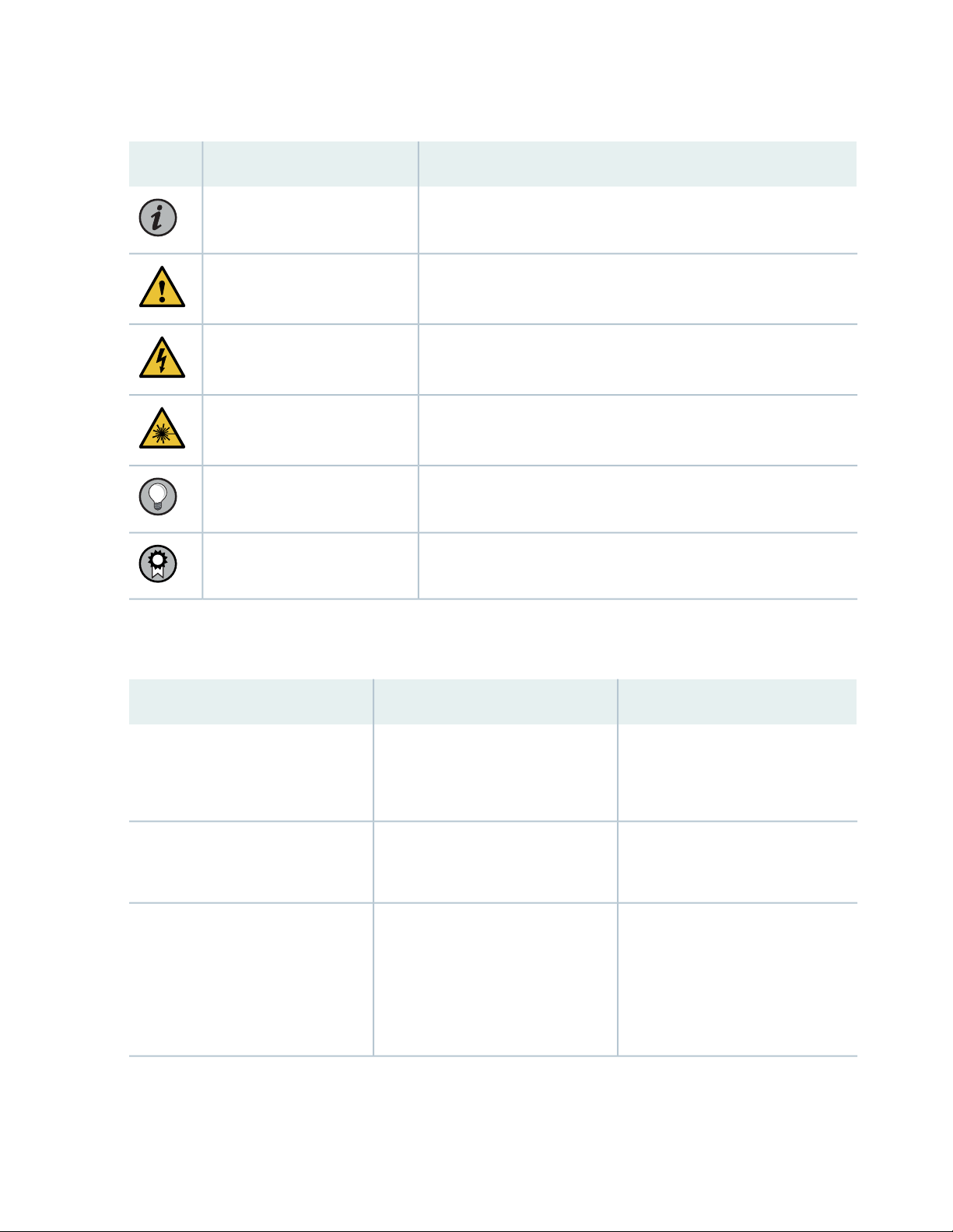
Table 1: Notice Icons
v
DescriptionMeaningIcon
Indicates important features or instructions.Informational note
Caution
Indicates a situation that might result in loss of data or hardware
damage.
Alerts you to the risk of personal injury or death.Warning
Alerts you to the risk of personal injury from a laser.Laser warning
Indicates helpful information.Tip
Alerts you to a recommended use or implementation.Best practice
Table 2 on page v defines the text and syntax conventions used in this guide.
Table 2: Text and Syntax Conventions
ExamplesDescriptionConvention
Fixed-width text like this
Italic text like this
Represents text that you type.Bold text like this
Represents output that appears on
the terminal screen.
Introduces or emphasizes important
•
new terms.
Identifies guide names.
•
Identifies RFC and Internet draft
•
titles.
To enter configuration mode, type
the configure command:
user@host> configure
user@host> show chassis alarms
No alarms currently active
A policy term is a named structure
•
that defines match conditions and
actions.
Junos OS CLI User Guide
•
RFC 1997, BGP Communities
•
Attribute
Page 6

Table 2: Text and Syntax Conventions (continued)
vi
ExamplesDescriptionConvention
Italic text like this
Text like this
< > (angle brackets)
| (pipe symbol)
Represents variables (options for
which you substitute a value) in
commands or configuration
statements.
Represents names of configuration
statements, commands, files, and
directories; configuration hierarchy
levels; or labels on routing platform
components.
variables.
Indicates a choice between the
mutually exclusive keywords or
variables on either side of the symbol.
The set of choices is often enclosed
in parentheses for clarity.
Configure the machine’s domain
name:
[edit]
root@# set system domain-name
domain-name
To configure a stub area, include
•
the stub statement at the [edit
protocols ospf area area-id]
hierarchy level.
The console port is labeled
•
CONSOLE.
stub <default-metric metric>;Encloses optional keywords or
broadcast | multicast
(string1 | string2 | string3)
# (pound sign)
[ ] (square brackets)
Indention and braces ( { } )
; (semicolon)
GUI Conventions
Indicates a comment specified on the
same line as the configuration
statement to which it applies.
Encloses a variable for which you can
substitute one or more values.
Identifies a level in the configuration
hierarchy.
Identifies a leaf statement at a
configuration hierarchy level.
rsvp { # Required for dynamic MPLS
only
community name members [
community-ids ]
[edit]
routing-options {
static {
route default {
nexthop address;
retain;
}
}
}
Page 7

Table 2: Text and Syntax Conventions (continued)
vii
ExamplesDescriptionConvention
Bold text like this
> (bold right angle bracket)
Represents graphical user interface
(GUI) items you click or select.
Separates levels in a hierarchy of
menu selections.
In the Logical Interfaces box, select
•
All Interfaces.
To cancel the configuration, click
•
Cancel.
In the configuration editor hierarchy,
select Protocols>Ospf.
Documentation Feedback
We encourage you to provide feedback so that we can improve our documentation. You can use either
of the following methods:
Online feedback system—Click TechLibrary Feedback, on the lower right of any page on the Juniper
•
Networks TechLibrary site, and do one of the following:
Click the thumbs-up icon if the information on the page was helpful to you.
•
Click the thumbs-down icon if the information on the page was not helpful to you or if you have
•
suggestions for improvement, and use the pop-up form to provide feedback.
E-mail—Send your comments to techpubs-comments@juniper.net. Include the document or topic name,
•
URL or page number, and software version (if applicable).
Requesting Technical Support
Technical product support is available through the Juniper Networks Technical Assistance Center (JTAC).
If you are a customer with an active Juniper Care or Partner Support Services support contract, or are
Page 8

covered under warranty, and need post-sales technical support, you can access our tools and resources
online or open a case with JTAC.
JTAC policies—For a complete understanding of our JTAC procedures and policies, review the JTAC User
•
Guide located at https://www.juniper.net/us/en/local/pdf/resource-guides/7100059-en.pdf.
Product warranties—For product warranty information, visit https://www.juniper.net/support/warranty/.
•
JTAC hours of operation—The JTAC centers have resources available 24 hours a day, 7 days a week,
•
365 days a year.
Self-Help Online Tools and Resources
For quick and easy problem resolution, Juniper Networks has designed an online self-service portal called
the Customer Support Center (CSC) that provides you with the following features:
Find CSC offerings: https://www.juniper.net/customers/support/
•
Search for known bugs: https://prsearch.juniper.net/
•
viii
Find product documentation: https://www.juniper.net/documentation/
•
Find solutions and answer questions using our Knowledge Base: https://kb.juniper.net/
•
Download the latest versions of software and review release notes:
•
https://www.juniper.net/customers/csc/software/
Search technical bulletins for relevant hardware and software notifications:
•
https://kb.juniper.net/InfoCenter/
Join and participate in the Juniper Networks Community Forum:
•
https://www.juniper.net/company/communities/
Create a service request online: https://myjuniper.juniper.net
•
To verify service entitlement by product serial number, use our Serial Number Entitlement (SNE) Tool:
https://entitlementsearch.juniper.net/entitlementsearch/
Creating a Service Request with JTAC
You can create a service request with JTAC on the Web or by telephone.
Visit https://myjuniper.juniper.net.
•
Call 1-888-314-JTAC (1-888-314-5822 toll-free in the USA, Canada, and Mexico).
•
For international or direct-dial options in countries without toll-free numbers, see
https://support.juniper.net/support/requesting-support/.
Page 9

1
CHAPTER
All-in-One Quick Start Guide
Overview | 10
Manager of Central Managers (MCM) | 10
Extensible Installations | 11
Installing the Juniper ATP Appliance All-in-One Hardware Appliance | 12
Configuring the Juniper ATP Appliance All-in-One System | 14
Changing the Appliance Type | 18
FIPS Mode Overview | 20
Setting the Same Device Key Passphrase on all Juniper ATP Appliance Devices | 24
Verifying Configurations | 25
Accessing the Juniper ATP Appliance Central Manager Web UI | 26
Setting SSH Honeypot Detection | 27
Resetting the Administrator Password using CLI | 28
Page 10

Overview
Welcome to the Juniper Advanced Threat Prevention Appliance All-in-One Quick Start Guide.
Juniper ATP Appliance’s continuous traffic-monitoring Collectors and multi-platform threat Detonation
Engines provide context-aware inspection, detection, and intelligence. Managed by the Juniper ATP
Appliance Central Manager, the All-in-One system inspects network traffic, extracts HTTP web and email
objects, then detonates and analyzes potential malware threats. Juniper ATP defines threat severity specific
to your environment. Results are reported through the Central Manager Web UI along with real-time
mitigation actions that reach all the way to the enterprise endpoint. SIEM integration is also supported.
Use this guide to perform initial setup of the combined “All In One” Central Manager/Core/Collector
Juniper ATP Server. Refer to the respective Quick Start Guides for separate Juniper ATP Appliance Traffic
Collector(s) servers and Mac OS X Engine Secondary Core installations.
10
RELATED DOCUMENTATION
Installing the Juniper ATP Appliance All-in-One Hardware Appliance | 12
Configuring the Juniper ATP Appliance All-in-One System | 14
Manager of Central Managers (MCM)
The Juniper ATP Appliance Manager of Central Managers (MCM) is a device that provides a Web UI
management console for Juniper ATP Appliance customers that deploy multiple Core/Central Managers
(CMs) in various geographic locations for which link speed limitations might constrain a single CM
deployment. The MCM allows customers with distributed enterprises to centralize their view of detected
malware incidents occurring on multiple CMs.
The MCM Platform device type is represented as “mcm” in the Juniper ATP Appliance CLI MCM command
mode. The MCM receives incident data from multiple Central Manager (CM) appliances and displays that
data in an MCM-mode Web UI.
The MCM Web UI is a subset of the larger Juniper ATP Appliance Central Manager Web UI and includes
only the incidents tab and the Config tab for System Profile configurations, in addition to a device Reset
and Logout tab.
RELATED DOCUMENTATION
Page 11

Installing the Juniper ATP Appliance All-in-One Hardware Appliance | 12
Configuring the Juniper ATP Appliance All-in-One System | 14
Extensible Installations
IN THIS SECTION
Firewall & Management Network Interface Connectivity | 11
Juniper ATP Appliance Server components can be installed as a single “All in One” appliance, or installed
separately as distributed devices for wider network visibility.
11
Juniper ATP Appliance For Windows
Detection
For Mac and Windows Detection
Combined Core Engine/Central Manager & Traffic Collector Server −
An “All In One” Server Appliance
An All-in-One Core Server Appliance with a separate, connected Mac
OS X Secondary Core
Firewall & Management Network Interface Connectivity
Connectivity requirements for the Juniper ATP Appliance management interface (eth0) allow for transfer
of inspected network and email objects, live malware behavior analysis, intel reporting, and product updates.
If the enterprise network firewall uses an outgoing “default allow” rule, this is sufficient. Otherwise, create
the following firewall rules:
Configure outgoing access from the Juniper ATP Appliance Core eth0 management interface to the
•
enterprise SMTP server, DNS servers, PAN or SRX Firewalls, BlueCoat or CarbonBlack servers, and
logging/SIEM servers.
Be sure any additional distributed Collector(s) can communicate with the Core/Central Manager over
•
port 443.
Page 12

Configure a management network proxy, or an “inside” or “outside” SPAN-traffic proxy using the CLI
•
“set proxy” commands; refer to the Juniper Advanced Threat Prevention Appliance CLI Command
Reference and Juniper Advanced Threat Prevention Operator’s Guide for more information.
For communication with Juniper ATP Appliance Logging and Update services, the Network Management
•
port (eth0) must be able to communicate to the Internet via port 443.
SEE ALSO
Installing the Juniper ATP Appliance All-in-One Hardware Appliance | 12
Installing the Juniper ATP Appliance All-in-One
12
Hardware Appliance
IN THIS SECTION
To Install the Juniper ATP Appliance Server | 12
For hardware specifications and set up instructions, refer to the Juniper Networks Advanced Threat
Prevention Appliance Hardware Guide. for your appliance model.
To Install the Juniper ATP Appliance Server
1. Access and download the raw image from the URL provided by Juniper and convert the raw image to
a bootable image. Create a bootable USB drive using this image. Kingston USB flash drives are
recommended. There are additional components (sandbox images) required for full functionality. These
are downloaded automatically at 12:00am local time after the initial system configuration is complete.
(Systems are shipped in PST timezone by default.)
2. Connect the eth0 management and eth1 network interfaces on the server that will host the Juniper
ATP software and confirm they are active links before beginning the software installation. Image
installation requires at least an active eth0 connection.
Page 13

3. Insert the USB drive containing the bootable image to the USB port of the server that will host the
Juniper ATP All-in-One software.
4. Use the down arrow keys to navigate the Boot Manager interface and down-arrow again to select the
USB port containing the image.
5. At the menu display, select only this option: INSTALL Juniper ATP SOFTWARE.
6. Follow the prompt to remove the USB; the system will reboot itself. This reboot may take up to 20
minutes.
7. After reboot, the Juniper ATP CLI prompt appears. At the CLI, log in to the Juniper ATP CLI with the
username admin and the password 1JATP234.
8. You will be prompted to insert the 2nd USB drive and to install the analysis engine images; answer the
prompts:
13
Do you want to update the guest images automatically [y/n]: n
Do you want to import the guest images from a URL [y/n]: n
Do you want to import the guest images from a USB [y/n]: y
9. Next, you must accept the EULA by selecting Yes when prompted.
10. You will be prompted to change the default CLI password. Enter a new password to begin configuring
the system.
NOTE: By default, JATP is installed as an All-In-One appliance. If you don’t want to install
the All-in-One Appliance, select one of the following types: 1 Core/Central Manager 2 Traffic
Collector 3 Email Collector 4 Manager Central Managers (MCM) 5 Return current form factor,
i.e. All-In-One.
After after the initial installation, you can change the appliance type but all data files related
to the current type are lost.
NOTE: Also note, if you are using MCM or Backup core with a previous release, you must
convert back to Core/CM before upgrading and using the new CLI “set appliance-type”
command to change the appliance type.
Page 14

NOTE: Starting in version 5.0.3, JATP supports FIPS mode, allowing JATP to operate in FIPS
140-2 level 1 compliant mode. FIPS mode is enabled or disabled using the CLI. If you intend to
enable FIPS mode, JATP passwords and keys must meet stronger FIPS mode specifications. For
instructions for enabling FIPS mode and prerequisites, see “FIPS Mode Overview” on page 20.
NOTE: To wipe the device, it is recommended you use DBAN software. Those instructions can
be found here: https://www.lifewire.com/how-to-erase-a-hard-drive-using-dban-2619148
SEE ALSO
FIPS Mode Overview | 20
14
Configuring the Juniper ATP Appliance All-in-One System
IN THIS SECTION
Logging into the Juniper ATP Appliance All-in-One CLI | 14
If you are powering up an All -in-One system in order to change initial configuration settings, you will need
to log in as described immediately below.
The Juniper ATP Appliance Configuration wizard steps you through initial configuration of the Juniper
ATP Appliance All-in-One system. To exit the CLI, type exit.
Logging into the Juniper ATP Appliance All-in-One CLI
1. Log in to the Juniper ATP Appliance CLI with the username admin and the password 1JATP234.
Page 15

2. When prompted with the query “Do you want to configure the system using the Configuration Wizard
(Yes/ No)?”, enter yes.
Using the Configuration Wizard
Customer Response ActionsConfiguration Wizard Prompts
15
Use DHCP to obtain the IP address and DNS server
address for the administrative interface (Yes/No)?
Note: Only if your DHCP response is no,enter the
following information when prompted:
a. Enter a gateway IP address and netmask for this
management (administrative) interface:
b. Enter primary DNS server IP address.
c. Do you have a secondary DNS Server (Yes/No).
d. Do you want to enter the search domains?
e. Enter the search domain (separate multiple search
domains by space):
Restart the administrative interface (Yes/No)?
Enter a valid hostname.
We strongly discourage the use of DHCP addressing for
the eth0 interface because it changes dynamically. A static
IP address is preferred.
Recommended: Respond with no:
a. Enter a gateway IP X.X.X.X and quad-tuple netmask
using the form 255.255.255.0 (no CIDR format).
b. Enter the primary DNS IP address
c. If yes, enter the IP address of the secondary DNS
server.
d. Enter yes if you want DNS lookups to use a specific
domain.
e. Enter search domain(s) separated by spaces; for
example: example.com lan.com dom2.com
Enter yes to restart with the new configuration settings
applied.
Type a unique hostname when prompted; do not include
the domain. A hostname should not include any spaces;
for example: juniper-atp1
Page 16

16
Customer Response ActionsConfiguration Wizard Prompts
[OPTIONAL]
f the system detects a Secondary Core with an eth2 port,
then the alternate CnC exhaust option is displayed:
Use alternate-exhaust for the analysis engine exhaust
traffic (Yes/No)?
Enter IP address for the alternateexhaust (eth2) interface:
Enter netmask for the alternateexhaust (eth2) interface:
(example: 255.255.0.0)
Enter gateway IP Address for the alternate-exhaust (eth2)
interface: (example:10.6.0.1)
Enter primary DNS server IP Address for the
alternate-exhaust (eth2) interface: (example: 8.8.8.8)
Do you have a secondary DNS server for the
alternate-exhaust (eth2) interface?
Do you want to enter the search domains for the
alternate-exhaust (eth2) interface?
Enter yes to configure an alternate eth2 interface.
Enter the IP address for the eth2 interface.
Enter the eth2 netmask.
Enter the gateway IP address.
Enter the primary DNS server IP Address for the
alternate-exhaust (eth2) interface.
Enter yes or no to confirm or deny an eth2 secondary
DNS server.
Enter yes or no to indicate whether you want to enter
search domain.
Note: A complete network interface restart can take more
than 60 seconds
Regenerate the SSL self-signed certificate (Yes/No)?
NOTE: The remaining Wizard prompts are specific to Collector or Secondary device configurations.
Enter the following server attributes:
Is this a Central Manager device:
Device Name: (must be unique)
Device Description
Device Key PassPhrase
NOTE: Remember this passphrase and use it for syncing
all distributed devices!
Enter yes to create a new SSL certificate for the Juniper
ATP Server Web UI.
If you decline the self-signed certificate by entering no,
be prepared to install a certificate authority (CA)
certificate.
Enter Yes; the system will auto-set IP 127.0.0.1 as the
All-in-One CM IP address.
Enter the Juniper ATP Collector Host Name; this identifies
the Collector in the Web UI.
Enter a device Description
Enter a user-defined PassPhrase to be used to
authenticate the Core to the Central Manager.
Page 17

NOTE: Enter CTRL-C to exit the Configuration Wizard at any time. If you exit without completing
the configuration, you will be prompted again whether to run the Configuration Wizard. You
may also rerun the Configuration Wizard at any time with the CLI command wizard. Please refer
to the Juniper ATP Appliance CLI Command Reference for further information regarding the
Juniper ATP Appliance Server command line.
SEE ALSO
Verifying Configurations | 25
FIPS Mode Overview | 20
17
Page 18

Changing the Appliance Type
In release version 5.0.4, a single ISO is provided for all appliance types (All-In-One, Email Collector, Traffic
Collector, Core/Central Manager). If you don’t change the form factor during the installation, all appliances
initially boot-up as an All-In-One appliance. You can keep this type or change the type by selecting a
different type in the wizard screen that appears following the EULA, after boot-up. See the hardware
installation guide for details.
In addition to changing the appliance type after the initial installation, you can change the appliance type
at any time using a new CLI command introduced in version 5.0.4 for both JATP700 and JATP400.
WARNING: If you change the appliance type after the initial installation, all data files
related to the current type are lost.
18
NOTE: After you change the appliance type, you must configure the device for the new type as
you would any new installation. Follow the installation procedure in the documentation that
corresponds to the new appliance type, including setting the passphrase and following the
configuration wizard prompts. There is no limit to how many times you can change the appliance
type.
To change the appliance type using the CLI, enter the following command while in server mode. (Note
that the current appliance type is displayed at the prompt. In this case, the type is “AIO,” which is
All-In-One.):
jatp:AIO#(server)# set appliance-type core-cm
This will result in the deletion of all data and configurations not relevant to the
new form factor.
Proceed? (Yes/No)? Yes
The appliance types available from the set appliance-type command are listed below and displayed in the
following CLI screen:
all-in-one
•
core-cm
•
email-collector
•
traffic-collector
•
Page 19

NOTE: When an Email Collector or Traffic Collector is converted to an All In One or Core/CM,
you must obtain and apply a new license created for that device identified by its UUID. This is
because, after the conversion, the device still uses the existing license, which it obtained and
validated from the Core it was connected to previously. Refer to Setting the Juniper ATP Appliance
License Key in the Operator’s Guide for instructions on applying a new license.
Figure 1: Available Appliance Types, CLI appliance-type Command
19
As mentioned previously, if you change the appliance type after the initial installation, all data files related
to the current type are lost. Here are examples of the information that is lost when the appliance type is
changed.
Core/CM—If Core/CM is removed from the current appliance type, that will result in the deletion of the
•
following data: all user configurations such as notifications (alert and SIEM settings), system profiles
(roles, zones, users, SAML, systems, GSS, collectors and other settings), environmental settings (email
and firewall mitigation settings, asset value, identity, splunk configuration and other environmental
settings), all file samples, analysis results, events and incidents.
Traffic Collector—If Traffic Collector is removed from the current appliance type, that will result in the
•
deletion of the following data: the data path proxy, traffic rules and all other items configured through
the collector CLI.
Page 20

Email Collector—If Email Collector is removed from the current appliance type, that will result in the
•
deletion of collector related information. Also note that the Email Collector will stop receiving emails.
All-In-One—If All-In-One is removed from the current appliance type, that will result in the following:
•
If you convert from All-In-One to Traffic Collector, then all items mentioned in the Core/CM section
•
above will be removed.
If you convert from All-In-One to Core/CM, then all settings mentioned in the Traffic Collector section
•
above will be removed.
If you convert from All-In-One to Email Collector, then all settings mentioned in both the Core/CM
•
and Traffic Collector sections above will be removed.
NOTE: If you are using MCM or Secondary Core and want to change the appliance type to one
of the choices available from the “set appliance-type” CLI command, you must first do the
following:
Convert the MCM system back to a Core/CM system by running the set mcm remove command
•
from the cm menu.
20
Convert from a Secondary Core system to a Core system by resetting the CM IP address to
•
127.0.0.1 and running the set cm 127.0.0.1 command from the server menu.
FIPS Mode Overview
IN THIS SECTION
Enable FIPS Mode | 21
Reset Passwords and Keys | 23
Page 21

Enable FIPS Mode
Federal Information Processing Standards (FIPS) are standards provided by the United Stated Federal
government for the purpose of secure interoperability among computing systems. These standards include
encryption and common codes for various types of information, such as emergencies in certain geographic
locations.
Starting in release 5.0.3, JATP provides FIPS support, allowing JATP to operate in FIPS 140-2 level 1
compliant mode. From this release onward, JATP can operate in either FIPS or non-FIPS mode.
FIPS mode is enabled or disabled using the CLI. Before you enable FIPS mode, there are several points
you should be aware of.
In clustered deployments, all systems must either be in FIPS mode or not in FIPS mode. This is due to
•
differences in how the device keys are calculated between modes. The same restriction applies for MCM
configurations.
Before enabling FIPS mode, please ensure that the Core/CM, secondary cores, collectors, and other
•
JATP appliances have been successfully upgraded to release 5.0.3 or higher. Enabling FIPS mode will
prevent non-FIPS appliances from communicating with, and upgrading from, the Core/CM appliance.
21
FIPS mode requires stronger encryption for passwords and keys than non-FIPS mode. Please note the
•
following requirements:
Password length (both CLI and UI) must be between 10 to 20 characters long. Passwords cannot use
•
common insecure entries as part of the password, such as “password” or “123456.” Passwords do not
have any character uppercase, lowercase, or symbol requirements.
User-provided UI private keys must be RSA, 2048 bits or higher.
•
User-provided UI certificates cannot use the following certificate signature hash algorithms: md2,
•
mdc2, ripemd, md4, md5
When FIPS mode is enabled, PKCS#12 bundles uploaded to the JATP Core/CM require strong
•
encryption. PKCS#12 bundles with weak encryption cannot be decrypted and the keypair will not be
applied to the UI. Use PBE-SHA1-3DES for the keypbe and certpbe arguments when creating PKCS#12
bundles with the 'openssl pkcs12' command. If the encryption is too weak, you may see the following
error message: “Couldn't process SSL Certificate: Error: Failed to extract private key from PKCS#12
bundle.”
NOTE: If the above requirements are not met, when you run the command to enable FIPS, the
output will indicate the issues you must correct.
Page 22

WARNING: For existing deployed appliances, you may be prompted to reset the UI
and CLI passwords when putting the appliance into FIPS mode. This is because stored
passwords are hashed, and it cannot be determined whether or not those passwords
meet FIPS requirements.
Enable FIPS mode using the CLI in server mode as follows:
NOTE: If the current password does not meet the FIPS requirements stated above, you must
change it before enabling FIPS mode.
Use the set fips command with following options to enable and disable FIPS:
eng-dhcp (server)# set fips
22
Available options are:
level —Select FIPS 140-2 security level
off —Disable FIPS 140-2 settings
Level 1 is only valid entry at this time. For example, turn FIPS on with the following command:
eng-dhcp (server)# set fips level 1
NOTE: If all requirements are met and the command is successful, you are prompted to reboot
the appliance. FIPS mode settings are applied after the reboot.
Turn FIPS off with the following command:
eng-dhcp (server)# set fips off
View FIPS settings with the following command:
eng-dhcp (server)# show fips
View FIPS issues with the following command:
Page 23

eng-dhcp (diagnosis)# show fips errors
Reset Passwords and Keys
To reset your passwords and keys (in preparation for enabling FIPS mode or for any other reason):
Enter the reset command in server mode:
eng-dhcp(server)# reset
options are:
ui —Reset all UI settings and remove non-default UI users
passwords —Reset default CLI and UI passwords
23
keys —Regenerate internal keys and certificates
all —Reset passwords and keys
For example, reset passwords and keys with the following command:
eng-dhcp(server)# reset all
Example Output:
Update passphrases and default accounts ...
Enter the current password of CLI admin:
Enter the new password of CLI admin:
Retype the new password of CLI admin:
Password changed successfully!
Enter the new password of the Central Manager UI account:
Retype the new password of the Central Manager UI account:
Password changed successfully!
Enter new devicekey: securephrase3
Recreating internal keys/certificates (1/4) ...
Recreating internal keys/certificates (2/4) ...
Recreating internal keys/certificates (3/4) ...
Regenerate the SSL self-signed certificate? (Yes/No)? Yes
SSL Self-signed certificate re-generated successfully!
Recreating internal keys/certificates (4/4) ...
This will remove all UI configurations and UI users, except for the default admin
user. All settings, including software/content update, RADIUS, SAML and GSS settings
will be reset to the default settings.
Page 24

Proceed? (Yes/No)? Yes
----Restarting all services----
NOTE: The following prompts from the output above are only applicable for the Core/CM or
All-in-one appliance. They are not shown for collectors and secondary cores.
Enter the new password of the Central Manager UI account:
Retype the new password of the Central Manager UI account: Password changed successfully!
This will remove all user configurations and UI users, except for the default admin user.
Proceed? (Yes/No)? Yes
24
Setting the Same Device Key Passphrase on all Juniper ATP Appliance Devices
The same device key must be set on all Juniper ATP Appliance devices in your network, no matter how
remote the distributed devices may be. To set a device key passphrase, SSH into the device, login, and use
the following CLI commands:
JATP(server)# set passphrase <strongPassphraseHash>
JATP(server)# show device key
Most characters are valid for the passphrase, except for the following cases:
Passphrases including white spaces must be put inside quotations “”.
•
Passphrases including the character \ must be put inside quotations “”.
•
If the passphrase includes the “ character, the “ character itself needs to be escaped.
•
Always use the latest version of Putty for SSH operations, if using Putty as an SSH client.
Page 25

Verifying Configurations
To verify interface configurations, use the following CLI commands (refer to the CLI Command Reference
Guide for more information):
PurposeCLI Mode & Command
Run a check of all system componentsJATP (diagnosis)# setupcheck all
Verify interface connectivity and statusJATP (server)# show interface
Verify traffic [example: show ip eth1]JATP (server)# show ip <interface>
Display All-in-One Collector statisticsJATP (diagnosis)# show device collectorstatus
Ping connected devices.JATP (server)# ping x.x.x.x
25
JATP (diagnosis)# capture-start <IP address>
<interface>
JATP (server)# shutdown
NOTE: Be sure to refer to the Juniper ATP CLI Command Reference for more information. Special characters used
in CLI parameters must be enclosed in double quotation marks.
Starts packet capture as a means for diagnosing and debugging
network traffic and obtaining stats (not part of the Collector
traffic capture engine).
Shutdown before moving a devices to a different location, or
to perform server room maintenance etc
RELATED DOCUMENTATION
Accessing the Juniper ATP Appliance Central Manager Web UI | 26
Page 26

Accessing the Juniper ATP Appliance Central Manager Web UI
IN THIS SECTION
To Log in to the Central Manager Web UI | 26
NOTE: To access the Juniper ATP Appliance Central Manager (CM) Web UI, use HTTP/HTTPS
and enter the configured Juniper ATP Appliance CM IP address or hostname in a web browser
address field, then accept the SSL certificate when prompted. Login is required.
26
NOTE: Be sure any distributed devices (additional Collectors or Mac OS X Engines) connected
to the Allin- One system are configured with the same device key as defined by the CLI command
set passphrase. If you do not set the same passphrase on all devices, you will not be able to see
the Collector or the Mac OS X Engine in the Web UI.
To Log in to the Central Manager Web UI
1. In the Juniper ATP Login window, enter the default username admin and the password juniper.
2. When prompted to reset the password, re-enter the password juniper as the “old” password, and enter
a new password (twice).
NOTE: The CM Web UI supports passwords up to 32 characters, and at least 8 characters.
Letters (uppercase/lowercase), numbers, and special characters can be used with the exception
of double-quotes (”), spaces, or backslash characters (\) in passwords.
Page 27

Web UI Navigation Tabs
Dashboard : Review incontext malware summaries lateral progressions and trends: Operations, Research,
•
System, Collectors, Events Timeline.
Incidents: View detected incidents and their behaviors.
•
File Uploads: Upload files for analysis.
•
Mitigation: Perform immediate threat verification & mitigation.
•
Figure 2: Central Manager Dashboard
27
The Juniper ATP Appliance CM Dashboard provides in-context and aggregated malware detection
information as well as system status and health information. Additional configurations are made from the
Configuration tab. Refer to the Operator's Guide for more information.
Setting SSH Honeypot Detection
A honeypot deployed within a customer enterprise network can be used to detect network activity
generated by malware attempting to infect or attack other machines in a local area network. Attempted
SSH login honeypots are used to supplement detection of lateral spread events. A honeypot can be deployed
on a customer Traffic Collector from which event information is sent to the Juniper ATP Appliance Core
for processing. Customers can place a honeypot on any local network they desire.
Page 28

A malicious actor attempting to perform brute force SSH entry, or execute targeted SSH access to a “root”
account, will also be detected by the Juniper ATP Appliance SSH Honeypot feature.
Results of SSH Honeypot detections are displayed on the Central Manager Web UI Incidents page, and
included in generated Reports.
Data sent to the Juniper ATP Appliance GSS for honeypot detection events include “Threat Target” and
a detailing of all attempted “SSH sessions” (including username and password) with timestamps.
A honeypots can operate on a Juniper ATP Appliance All-in-One system or on a Traffic Collector-only
device, as long as the host has enough physical interfaces. Each honeypot uses two interfaces, one
externally-facing interface for internet/intranet traffic and one for internal host-to-guest communication.
This means that each honeypot will use the eth3 interface for all outbound traffic.
Resetting the Administrator Password using CLI
28
WARNING: To reset the administrator password using CLI, you must have physical
access to the appliance. You cannot reset the administrator password remotely.
A user with the name “recovery” can log into the appliance without a password and enter a limited amount
of commands, including a command to reset the administrator password.
To recover the administrator password using CLI, do the following:
1. When prompted to login, enter the username recovery on the appliance and press Enter.
user login: recovery
*******************************************************************
Juniper Networks Advanced Threat Prevention Appliance
*******************************************************************
Welcome recovery. It is now Wed Jan 01 12: 00:00 PDT 2020
user:Core#
exit help history
reset-admin-password
Since no password is required the recovery user is automatically logged into the device.
2. Enter the reset-admin-password command to reset the password.
Page 29

user:Core# reset-admin-password
The other commands available to the recovery user are: exit, help, and history.
In addition to viewing UI users in the audit logs, you can also view admin and recovery-admin CLI users
in the audit logs, under Reports in the Web UI. See the Operator’s Guide for details.
29
 Loading...