

Page 1

ACX500 Universal Access Routers Quick
Start—ACX500 Indoor Routers
August 2015
Part Number: 530-061428
Revision 02
This document describes how to install the Juniper Networks®ACX500 Universal Access
Routers—the ACX500 indoor routers.
Contents
ACX500 Routers Quick Start Description . . . . . . . . . . . . . . . . . . . . . . . . . . . . . . . . . 3
Step 1: Prepare the Site for Installation . . . . . . . . . . . . . . . . . . . . . . . . . . . . . . . . . . . 6
Step 2: Install the Router . . . . . . . . . . . . . . . . . . . . . . . . . . . . . . . . . . . . . . . . . . . . . . 8
Tools Required to Install the ACX500 Indoor Router in a Rack . . . . . . . . . . . . . 8
Install the Mounting Brackets . . . . . . . . . . . . . . . . . . . . . . . . . . . . . . . . . . . . . . . 8
Install the ACX500 Indoor Router in a Rack . . . . . . . . . . . . . . . . . . . . . . . . . . . 9
Step 3: Ground the ACX500 Indoor Router . . . . . . . . . . . . . . . . . . . . . . . . . . . . . . . 10
Tools Required to Ground the Router . . . . . . . . . . . . . . . . . . . . . . . . . . . . . . . . 10
Connect the Grounding Cable . . . . . . . . . . . . . . . . . . . . . . . . . . . . . . . . . . . . . . 10
Step 4: Connect External Devices and Cables . . . . . . . . . . . . . . . . . . . . . . . . . . . . . 12
Tools Required to Connect External Devices and Cables . . . . . . . . . . . . . . . . . 12
Connect the ACX500 Router to a Network for Out-of-Band
Management . . . . . . . . . . . . . . . . . . . . . . . . . . . . . . . . . . . . . . . . . . . . . . . . 12
Connect the ACX500 Router to a Management Console Device . . . . . . . . . . 12
Connect Network Interface Cables to the ACX500 Router . . . . . . . . . . . . . . . 12
Step 5: Connect Power to the ACX Series Router . . . . . . . . . . . . . . . . . . . . . . . . . . 14
Connect Power to an AC-Powered ACX500 Router . . . . . . . . . . . . . . . . . . . . 14
Connect Power to a DC-Powered ACX500 Router . . . . . . . . . . . . . . . . . . . . . 15
Step 6: Perform Initial Software Configuration . . . . . . . . . . . . . . . . . . . . . . . . . . . . 18
Enter Configuration Mode . . . . . . . . . . . . . . . . . . . . . . . . . . . . . . . . . . . . . . . . . 18
Configure User Accounts and Passwords . . . . . . . . . . . . . . . . . . . . . . . . . . . . . 18
Configure System Attributes . . . . . . . . . . . . . . . . . . . . . . . . . . . . . . . . . . . . . . . 19
Commit the Configuration . . . . . . . . . . . . . . . . . . . . . . . . . . . . . . . . . . . . . . . . . 19
Safety Warnings . . . . . . . . . . . . . . . . . . . . . . . . . . . . . . . . . . . . . . . . . . . . . . . . . . . . 21
Compliance Statements for NEBS . . . . . . . . . . . . . . . . . . . . . . . . . . . . . . . . . . . . . 22
Compliance Statements for EMC Requirements for ACX500 Routers . . . . . . . . . 23
Canada . . . . . . . . . . . . . . . . . . . . . . . . . . . . . . . . . . . . . . . . . . . . . . . . . . . . . . . 23
European Community . . . . . . . . . . . . . . . . . . . . . . . . . . . . . . . . . . . . . . . . . . . . 23
1
Page 2

ACX500 Universal Access Routers Quick Start—ACX500 Indoor Routers
Israel . . . . . . . . . . . . . . . . . . . . . . . . . . . . . . . . . . . . . . . . . . . . . . . . . . . . . . . . . 23
Japan . . . . . . . . . . . . . . . . . . . . . . . . . . . . . . . . . . . . . . . . . . . . . . . . . . . . . . . . . 23
United States . . . . . . . . . . . . . . . . . . . . . . . . . . . . . . . . . . . . . . . . . . . . . . . . . . . 23
Junos OS Documentation and Release Notes . . . . . . . . . . . . . . . . . . . . . . . . . . . . 25
Requesting Technical Support . . . . . . . . . . . . . . . . . . . . . . . . . . . . . . . . . . . . . . . . . 25
Self-Help Online Tools and Resources . . . . . . . . . . . . . . . . . . . . . . . . . . . . . . . 25
Opening a Case with JTAC . . . . . . . . . . . . . . . . . . . . . . . . . . . . . . . . . . . . . . . . 26
Revision History . . . . . . . . . . . . . . . . . . . . . . . . . . . . . . . . . . . . . . . . . . . . . . . . . . . . 26
2
Page 3

ACX500 Routers Quick Start Description
This Quick Start contains information you need to install and configure the ACX500
indoor router quickly. For complete installation instructions, see the ACX500 Universal
Access Router Hardware Guide at http://www.juniper.net/techpubs/.
WARNING: This Quick Start containsa summary of safetywarnings in “Safety
Warnings” on page 21. For a completelist of warnings for this router, including
translations, see the ACX500 Universal Access Router Hardware Guide at
http://www.juniper.net/techpubs/.
The ACX Series Universal Access Routers are Ethernet-optimized mobile backhaul routers
that provide both switching and carrier-class Ethernet routing. The ACX Series routers
enable a wide range of business and residential applications and services, including
microwave cell site aggregation,mobile backhaul service cell site deployment, and service
provider or operator cell site deployment. The routers have high-density Ethernet
interfaces and high-capacity switching throughput.
ACX500 Routers Quick Start Description
An ACX Series router has a built-in Routing Engine and one Packet Forwarding Engine.
The Packet Forwarding Engine has one “pseudo” Flexible PIC Concentrator (FPC 0).
Because there is no switching fabric, the single Packet Forwarding Engine takes care of
packet forwarding.
The compact ACX500 indoor router is one rack unit (U; that is, 1.75 in., or 4.45 cm) tall.
Several routers can be stacked in a single floor-to-ceiling rack for increased port density
per unit of floor space. The chassis is a rigid sheet metal structure that houses all the
other router components. The chassis of the ACX500 indoor router measures 1.75 in.
(4.45 cm) high, 9.4 in. (24 cm) deep, and 17.5 in. (44.5 cm) wide. The outer edges of the
mounting brackets extend the width to 19.2 in. (48.7 cm) (with mounting brackets
attached). The chassis installs in standard 300-mm deep (or larger) enclosed cabinets,
19-in. equipment racks, or telco open-frame racks. The ACX500 indoor router is available
in both AC and DC models.
The ACX500 indoor router contains a total of 10 Gigabit Ethernet ports, eight of which
are labeled COMBO. At any point of time, you can use a maximum of six ports.
The ports labeled COMBO (combination ports) consist of four RJ-45 ports and four
Gigabit Ethernet SFP ports. Out of the four RJ-45 ports, three ports support PoE (PoE+
and PoE++).
The two ports that are not part of the COMBO ports are the Gigabit Ethernet SFP ports.
On the ACX500, the six ports that you can use at any point of time can be two Gigabit
Ethernet SFP ports (non-combination) and four ports from the COMBO ports.
3
Page 4

ACX500 Universal Access Routers Quick Start—ACX500 Indoor Routers
NOTE: You can mix and match the four RJ-45 and SFP COMBO ports as long
as the port numbers are unique.
For example, from the COMBO ports, you can use the SFP port 0/1/0 along
with the RJ-45 port 0/1/1 PoE+, but not the RJ-45 port 0/1/0 PoE++, because
the port numbers of the SFP and the RJ-45 ports are the same (0/1/0).
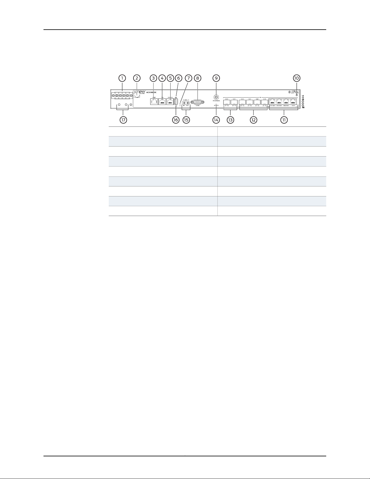
Figure 1 on page 4 and Figure 2 on page 5 show the front panels of the AC-powered
and DC-powered ACX500 indoor routers, respectively.
Figure 1: Front Panel of the AC-Powered ACX500 Indoor Router
Management Ethernet port
USB port
Alarm contact port
9—1— ESD pointAC terminals
10—2—
Gigabit Ethernet RJ-45 ports (COMBO)
11—3—
Gigabit Ethernet SFP ports (COMBO)Time of day (TOD) RJ-45 port
12—4— Gigabit Ethernet SFP portsConsole port
13—5—
GPS LED (GPS 1PPS)
14—6— External clocking portsRecovery switch
15—7—
System status LED (SYS)
16—8— Grounding terminalsGPS antenna port
4
Page 5
ACX500 Routers Quick Start Description
Figure 2: Front Panel of the DC-Powered ACX500 Indoor Router
10—1— ESD pointDC terminals
DC power status LED
Management Ethernet port
Time of day (TOD) RJ-45 port
Console port
Recovery switch
9—GPS antenna port
11—2—
Gigabit Ethernet RJ-45 ports (COMBO)
12—3—
Gigabit Ethernet SFP ports (COMBO)
13—4— Gigabit Ethernet SFP ports
14—5—
GPS LED (GPS 1PPS)
15—6— External clocking portsUSB port
16—7—
System status LED (SYS)
17—8— Grounding terminalsAlarm contact port
5
Page 6

ACX500 Universal Access Routers Quick Start—ACX500 Indoor Routers
Step 1: Prepare the Site for Installation
Prepare your site for installation by observing the following guidelines:
•
You can install the router in a four-post rack or cabinet or in an open-frame rack.
•
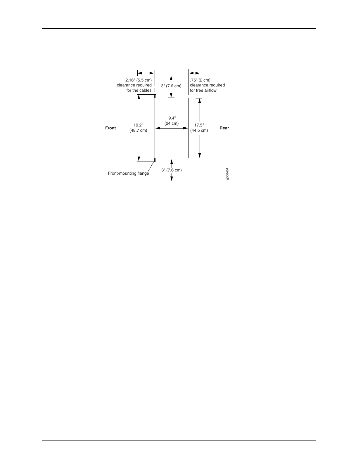
The rack rails must be spaced widely enough to accommodate the chassis's external
dimensions: 1.75 in. (4.4 cm) high, 9.4 in. (24 cm) deep, and 17.5 in. (44 cm) wide. The
outer edges of the mounting brackets extend the width to 19.2 in. (48.7 cm). See
Figure 3 on page 7.
•
One person must be available to lift the router while another secures the router to the
rack.
•
The rack must be strong enough to support the weight of the fully configured router,
up to 8.6 lb (3.9 kg).
•
For service personnel to remove and install hardware components, allow at least
2.16 in. (5.5 cm) in front of the router.
•
The rack or cabinet must have an adequate supply of cooling air. Allow a minimum of
1 meter per second of airflow over the ACX500 indoor router.
•
Ensure that the cabinet allows the hot exhaust air of the chassis to exit from the cabinet
without recirculating into the router.
•
When deploying the router in environments where the router might operate between
68° F (20° C) and 149° F (65° C), allow a 1 U gap above and below the router.
•
When you are installing the router in a cabinet, ensure that the bottom of the cabinet
is closed.
•
You must install the router into a rack that is secured to the building structure.
•
Mount the router at the bottom of the rack if it is the only unit in the rack.
•
When mounting the router in a partially filled rack, load the rack from the bottom to
the top, with the heaviest component at the bottom of the rack.
•
Install the router only in restricted areas, such as dedicated equipment rooms and
equipment closets, in accordance with Articles 110-16, 110-17,and 110-18 of the National
Electrical Code, ANSI/NFPA 70.
6
Page 7
RearFront
17.5"
(44.5 cm)
9.4"
(24 cm)
g006404
Front-mounting flange
19.2"
(48.7 cm)
2.16" (5.5 cm)
clearance required
for the cables
.75" (2 cm)
clearance required
for free airflow
3" (7.6 cm)
3" (7.6 cm)
Step 1: Prepare the Site for Installation
Figure 3: ACX500 Indoor Router Rack Clearanceand Chassis Dimensions
7
Page 8
g006405
g006406
ACX500 Universal Access Routers Quick Start—ACX500 Indoor Routers
Step 2: Install the Router
•
Tools Required to Install the ACX500 Indoor Router in a Rack on page 8
•
Install the Mounting Brackets on page 8
•
Install the ACX500 Indoor Router in a Rack on page 9
Tools Required to Install the ACX500 Indoor Router in a Rack
To install the router in a rack, you need the following tools:
•
Phillips (+) screwdriver, number 2
Install the Mounting Brackets
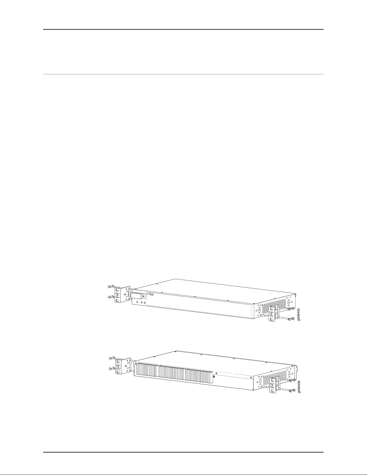
Two mounting brackets for front or rear mounting ship with the router (see
Figure 4 on page 8 and Figure 5 on page 8).
Attach both mounting brackets to either the front or rear of the chassis:
1. Align the bracket with the two sets of mounting holes of the chassis.
2. Insert the four screws at the top and bottom of the bracket and tighten each screw
partially.
3. Tighten the four screws completely.
4. Repeat the procedure for the other bracket.
Figure 4: Installing the Mounting Brackets to the Front of the ACX500
Indoor Router
Figure 5: Installing the Mounting Brackets to the Rear of the ACX500
Indoor Router
8
Page 9

Install the ACX500 Indoor Router in a Rack
g006407
Mounting rack
Mounting bracket
The ACX500 indoor router can be installed horizontally in a rack or cabinet. The router
can be accessed only from the front of the router. All components—such as ports, LEDs,
power unit, and so on are located in the front of the ACX500 indoor router.
One person must be available to lift the router while another secures the router to the
rack. The chassis weighs approximately 8.6 lb (3.9 kg). To install the chassis (see
Figure 6 on page 9):
1. Ensure that the rack is in its permanent location and is secured to the building. Ensure
that the installation site allows adequate clearance for both airflow and maintenance.
2. Position the router in front of the rack or cabinet.
3. Have one person grasp both sides of the router, lift the router, and position it in the
rack, aligning the mounting bracket holes with the threaded holes in the rack rails.
Make sure that the chassis is level.
4. Have the second person install a mounting screw into each of the open mounting
holes aligned with the rack, starting from the bottom.
Install the ACX500 Indoor Router in a Rack
5. Visually inspect the alignment of the router. If the router is installed properly in the
rack, all the mounting screws on one side of the rack should be aligned with the
mounting screws on the opposite side, and the router should be level.
Figure 6: Installing the Front-Mounted Router in the Rack
9
Page 10

ACX500 Universal Access Routers Quick Start—ACX500 Indoor Routers
Step 3: Ground the ACX500 Indoor Router
You must ground both the AC-powered and the DC-powered routers before connecting
them to power.
•
Tools Required to Ground the Router on page 10
•
Connect the Grounding Cable on page 10
Tools Required to Ground the Router
To ground the router, you need the following tools:
•
Phillips (+) screwdriver, number 2
•
Electrostatic discharge (ESD) grounding wrist strap
•
Two SAE 10-32 screws 0.25–0.5 in. long, and flat washers (not provided)
•
Grounding lug, Panduit LCD6-14BH-L or equivalent (not provided)
•
Grounding cable, minimum 14 AWG (2 mm2) 90° C wire (not provided)
Connect the Grounding Cable
You ground the router by connecting a grounding cable to earth ground and then attaching
it to the chassis grounding points. To ground the ACX500 indoor router:
1. Verify that a licensed electrician has attached the cable lug, which is provided with
the router, to the grounding cable.
2. Attach an electrostaticdischarge (ESD) grounding strap to your bare wrist, and connect
the strap to an approved site ESD grounding point. See the instructions for your site.
3. Ensure that all grounding surfaces are clean and brought to a bright finish before you
make grounding connections.
4. Connect the grounding cable to a proper earth ground.
5. Detach the ESD grounding strap from the site ESD grounding point.
6. Attach an ESD grounding strap to your bare wrist and connect the strap to one of the
ESD points on the chassis.
7. Place the grounding cable lug over the grounding points on the front of the chassis
(see Figure 7 on page 11).
NOTE: The grounding point location on the ACX500 is the same for both
the AC and the DC models.
8. Secure the grounding cable lug with the washers and screws. The holes are sized for
SAE 10-32 screws.
9. Dress the grounding cable, and verify that it does not touch or block access to router
components, and that it does not drape where people could trip on it.
10
Page 11

g006419
1
2
Connect the Grounding Cable
Figure 7: Grounding Points on the ACX500 Indoor Routers
2—1— SAE 10-32 screw and washerGrounding lug
11
Page 12

ACX500 Universal Access Routers Quick Start—ACX500 Indoor Routers
Step 4: Connect External Devices and Cables
•
Tools Required to Connect External Devices and Cables on page 12
•
Connect the ACX500 Router to a Network for Out-of-Band Management on page 12
•
Connect the ACX500 Router to a Management Console Device on page 12
•
Connect Network Interface Cables to the ACX500 Router on page 12
Tools Required to Connect External Devices and Cables
To connect external devices and cables to the router, you need the following tools:
•
Ethernet cable with an RJ-45 connector attached (provided)
•
RJ-45 to DB-9 serial port adapter (provided)
•
Management host, such as a PC, with an Ethernet port (not provided)
Figure 8: Ethernet Cable Connector
Connect the ACX500 Router to a Network for Out-of-Band Management
1. Turn off the power to the management device.
2. Plug one end of the Ethernet cable (Figure 8 on page 12 shows the connector) into
the MGMT port on the front of the chassis. Figure 2 on page 5 show the port.
3. Plug the other end of the cable into the network device.
Connect the ACX500 Router to a Management Console Device
1. Turn off the power to the console device.
2. Plug the RJ-45 end of the serial cable (Figure 8 on page 12 shows the connector) into
the CONSOLE port on the front panel. Figure 2 on page 5 show the port.
3. Plug the female DB-9 end into the device's serial port.
Connect Network Interface Cables to the ACX500 Router
1. Have ready a length of the type of cable used by the network ports. For cable
specifications, see the ACX500 Universal Access Router Hardware Guide.
NOTE: Shielded cables are required for outside deployment.
2. Remove the rubber safety plug from the cable connector port.
12
Page 13

Connect Network Interface Cables to the ACX500 Router
WARNING: Do not look directly into a fiber-optic transceiver or into the
ends of fiber-optic cables. Fiber-optic transceivers and fiber-optic cable
connected to a transceiver emit laser light that can damage your eyes.
CAUTION: Do not leave a fiber-optic transceiver uncovered except when
inserting or removing cable. The safety cap keeps the port clean and
prevents accidental exposure to laser light.
3. Insert the cable connector into the cable connector port on the faceplate.
4. Arrange the cable to prevent it from dislodging or developing stress points. Secure
the cable so that it is not supporting its own weight as it hangs to the floor. Place
excess cable out of the way in a neatly coiled loop.
CAUTION: Avoid bending fiber-optic cable beyond its minimum bend
radius. An arc smaller than a few inches in diameter can damage the cable
and cause problems that are difficult to diagnose.
CAUTION: Do not let fiber-optic cable hang free from the connector. Do
not allow fastened loops of cable to dangle, which stresses the cable at
the fastening point.
13
Page 14

ACX500 Universal Access Routers Quick Start—ACX500 Indoor Routers
Step 5: Connect Power to the ACX Series Router
Depending on your configuration, your router uses either AC or DC power supplies. Perform
the appropriate procedures for each power supply in your router.
•
Connect Power to an AC-Powered ACX500 Router on page 14
•
Connect Power to a DC-Powered ACX500 Router on page 15
Connect Power to an AC-Powered ACX500 Router
To connect power to the AC-powered router, you need the following tools:
•
AC power cords
•
ESD grounding wrist strap
1. Locate power cords that have a plug appropriate for your geographical location. For
more information, see the ACX500 Universal Access Routers Hardware Guide.
2. Attach an ESD grounding strap to your bare wrist and connect the strap to one of the
ESD points on the chassis.
3. Insert the appliance coupler end of the power cord into the appliance inlet on the
power supply. See Figure 9 on page 14.
4. Insert the power cord plug into an external AC power source receptacle.
NOTE: Each power supply must be connected to a dedicated AC power
feed and a dedicated customer-site circuit breaker. We recommend that
you use a dedicated customer-site circuit breaker rated for 2 A (100 VAC)
minimum or 1 A (240 VAC), or as required by local code.
5. Dress the power cord appropriately. Verify that the power cord does not block the air
exhaust and access to router components, or drape where people could trip on it.
6. Observe the system LED on the router. If an AC power supply is functioning normally,
the system LED lights green steadily.
If the system LED is not lit, the power supply is not functioning normally. Repeat the
cabling procedure.
Figure 9: Connecting AC Power to the Router
14
Page 15

Connect Power to a DC-Powered ACX500 Router
To connect power to the DC-powered router, you need the following tools:
•
Phillips (+) screwdriver, number 2
•
ESD grounding wrist strap
•
M3 screws and flat washers
•
DC power source cables, minimum 14 AWG or as required by local code (not provided)
•
Ring lugs, Molex 190700067 or equivalent (not provided)
The DC power supply has four terminals on the front panel, covered by a clear plastic
cover.
WARNING: You must ground the router before connecting the DC power
cables.
Connect Power to a DC-Powered ACX500 Router
Table 1: ACX Series DC Power System Input Voltage
SpecificationNominal Voltage
Operating range: +18 to +30 VDC+24
Operating range: –39 to –56 VDC–48
Operating range: –39 to –72 VDC–60
1. Attach an ESD grounding strap to your bare wrist, and connect the strap to one of the
ESD points on the chassis. For more information about ESD, see the ACX500Universal
Access Router Hardware Guide.
2. Switch off the dedicated customer-site circuit breakers. Ensure that the voltage across
the DC power source cable leads is 0 V and that there is no chance that the cable
leads might become active during installation.
3. Remove the clear plastic cover protecting the terminal on the faceplate.
4. Verify that the DC power cables are correctly labeled before making connections to
the power supply.In a typical power distribution scheme where the return is connected
to chassis ground at the battery plant, you can use a multimeter to verify the resistance
of the –48V, +24V, –60V, and the return DC cables to chassis ground:
For –48V and –60V:
a. The cable with very large resistance (indicating an open circuit) to chassis ground
is the DC input cable (+).
b. The cable with very low resistance (indicating a closed circuit) to chassis ground
is the return cable (–).
15
Page 16

ACX500 Universal Access Routers Quick Start—ACX500 Indoor Routers
For +24V:
a. The cable with very low resistance (indicating a closed circuit) to chassis ground
is the return cable (–).
b. The cable with very large resistance (indicating an open circuit) to chassis ground
is the DC input cable (+).
5. Remove the screws and flat washers from the terminals.
6. Secure each power cable lug to the terminal with the flat washers and screw (see
Figure 10 on page 17). Apply between 8 lb-in. (0.9Nm) and 9 lb-in. (1.02 Nm) of torque
to each screw. Do not overtighten the screw. (Use a number 2 Phillips screwdriver.)
a. Secure the positive DC source power cable lug to the return (+) terminal.
b. Secure the negative DC source power cable lug to the input (–) terminal.
CAUTION: Ensure that each power cable lug seats flush against the surface
of the terminal block as you tighten the screws. Ensure that each screw
is properly threaded into the terminal. Applying installation torque to the
screw when the screw is improperly threaded might result in damage to
the terminal.
CAUTION: The maximum torque rating of the terminal screws on the DC
powersupply is 9 lb-in. (1.02 Nm). The terminal screws might be damaged
if excessive torque is applied. Use only a torque-controlled driver to tighten
screws on the DC power supply terminals. Use an appropriately sized
driver, with a maximum torque capacity of 9 lb-in. or less. Ensure that the
driver is undamaged and properly calibrated and that you have been
trained in its use. Youmight want to use a driver that is designed to prevent
overtorque when the preset torque level is achieved.
7. Replace the clear plastic cover over the terminals on the faceplate.
8. Connect each DC power cable to the appropriate external DC power source.
NOTE: For information about connecting the router to external DC power
sources, see the instructions for your site.
9. Switch on the external circuit breakers to provide voltage to the DC power source
cable leads. Observe the system LED on front of the router. If the DC power cable is
correctly installed and functioning normally, the system LED lights green steadily. If
the system LED is not lit, the power supply is not functioning normally. Repeat the
installation and cabling procedures.
16
Page 17

g006409
Connect Power to a DC-Powered ACX500 Router
Figure 10: Connecting DC Power to the Router
17
Page 18

ACX500 Universal Access Routers Quick Start—ACX500 Indoor Routers
Step 6: Perform Initial Software Configuration
This procedure connects the router to the network but does not enable it to forward
traffic. For complete information about configuring the router to forward traffic, including
examples, see the Junos OS configuration guides.
To configure the software:
•
Enter Configuration Mode on page 18
•
Configure User Accounts and Passwords on page 18
•
Configure System Attributes on page 19
•
Commit the Configuration on page 19
Enter Configuration Mode
1. Verify that the router is powered on.
2. Log in as the root user. There is no password.
Amnesiac ttyd0
login: root
3. Start the CLI.
root@% cli
root>
4. Enter configuration mode.
root> configure
Entering configuration mode.
[edit]
root#
Configure User Accounts and Passwords
For information about using an encrypted password or an SSH public key string (DSA or
RSA), see the Junos OS System Basics Configuration Guide.
1. Add a password to the root administration user account. Enter a clear-text password.
[edit]
root# set system root-authentication plain-text-password
New password: password
Retype new password: password
2. Create a management console user account.
[edit]
root# set system login user user-name authentication plain-text-password
New Password: password
Retype new password: password
3. Set the user account class to super-user.
[edit]
18
Page 19

Configure System Attributes
For more information about configuring the backup routing and static routes, see the
Junos OS Administration Library for Routing Devices.
1. Configure the name of the router. If the name includes spaces, enclose the name in
quotation marks (“ ”).
[edit]
root@# set system host-name host-name
2. Configure the router’s domain name.
[edit]
root@# set system domain-name domain-name
3. Configure the IP address and prefix length for the router’s Ethernet interface.
[edit]
root@# set interfaces fxp0 unit 0 family inet address address/prefix-length
Configure System Attributes
root@# set system login user user-name class super-user
4. Configure the IP address of a backup router, which is used only while the routing
protocol is not running.
5. Configure the IP address of a DNS server.
6. (Optional) Configure the static routes to remote subnets with access to the
management port. Access to the management port is limited to the local subnet. To
access the management port from a remote subnet, you need to add a static route
to that subnet within the routing table. For more information about static routes, see
the Junos OS System Basics Configuration Guide.
7. Configure the Telnet service at the [edit system services] hierarchy level.
Commit the Configuration
1. (Optional) Display the configuration to verify that it is correct.
[edit]
root@# set system backup-router address
[edit]
root@# set system name-server address
[edit]
root@# set routing-options static route remote-subnet next-hop destination-IP retain
no-readvertise
[edit]
root@# set system services telnet
[edit]
root@# show
system {
host-name host-name;
domain-name domain-name;
backup-router address;
19
Page 20

ACX500 Universal Access Routers Quick Start—ACX500 Indoor Routers
root-authentication {
authentication-method (password | public-key);
}
name-server {
address;
}
}
interfaces {
fxp0 {
unit 0 {
family inet {
address address/prefix-length;
}
}
}
}
2. Commit the configuration to activate it on the router.
[edit]
root@# commit
3. (Optional) Configure additional properties by adding the necessary configuration
statements. Then commit the changes to activate them on the router.
[edit]
root@host# commit
4. When you have finished configuring the router, exit configuration mode.
[edit]
root@host# exit
root@host>
20
Page 21

Safety Warnings
Safety Warnings
WARNING: See installation instructions before connecting the router. This
is a summary of safety warnings. For a complete list of warnings for this
router, including translations, see the ACX500 Universal Access Router
Hardware Guide at http://www.juniper.net/techpubs/.
CAUTION: To comply with intrabuilding lightning and surge requirements,
intrabuilding wiring must be shielded, and the shield for the wiring must be
grounded at both ends.
WARNING: The intrabuilding ports of the router are suitable for connection
to intrabuilding or unexposed wiring or cabling only. The intrabuilding ports
of the router MUST NOT be metallically connectedto interfaces that connect
to the OSP or its wiring. These interfaces are designed for use as intrabuilding
interfaces only (Type 2 or Type 4 ports as described in GR-1089-CORE, Issue
4) and require isolation from the exposed OSP cabling. The addition of primary
protectors is not sufficient protection to connect these interfaces metallically
to OSP wiring.
CAUTION: Before removing or installing components of a router, attach an
ESD strap to an ESD point, and place the other end of the strap around your
bare wrist. Failure to use an ESD strap could result in damage to the router.
CAUTION: Use an external surge protective device (SPD) at the AC input of
the router.
•
Only trained and qualified personnel should install or replace the router.
•
Perform only the procedures described in this quick start or the ACX500 Universal
Access Router Hardware Guide. Other services should be performed by authorized
service personnel only.
•
Read the installation instructions before you connect the router to a power source.
•
Before installing the router, read the guidelines for site preparation in the ACX500
Universal Access Router Hardware Guide to make sure that the site meets power,
environmental, and clearance requirements for the router.
•
When installing the router, do not use a ramp inclined more than 10 degrees.
•
To prevent injury, keep your back straight and lift with your legs, not your back.
21
Page 22

ACX500 Universal Access Routers Quick Start—ACX500 Indoor Routers
•
Mount the router at the bottom of the rack if it is the only unit in the rack.
•
When mounting the router in a partially filled rack, load the rack from the bottom to
the top with the heaviest component at the bottom of the rack.
•
If the rack is provided with stabilizing devices, install the stabilizers before mounting
or servicing the router in the rack.
•
When removing or installing an electrical component, always place it component-side
up on a flat antistatic surface or in an electrostatic bag.
•
When you install the router, always make the ground connection first and disconnect
it last.
•
Wire the DC power supply by using the appropriate lugs.
•
Do not work on the system or connect or disconnect cables during electrical storms.
•
Beforeworking on equipment that is connectedto power lines, remove jewelry, including
rings, necklaces, and watches. Metal objects heat up when connected to power and
ground and can cause serious burns or become welded to the terminals.
•
Failure to observe these safety warnings can result in serious physical injury.
•
AC power cable warning (Japan):
WARNING:
Translation from Japanese—The attached power cable is only for this
product. Do not use the cable for another product.
•
The recommended maximum ambient temperature is 158° F (70° C). For safe operation,
take into consideration the internal temperature within the rack.
•
Note the hot surface warning label on the top rear of the chassis.
Compliance Statements for NEBS
•
The equipment is suitable for installation as part of the Common Bonding Network
(CBN).
22
•
The equipment is suitable for installation in locations where the National Electrical
Code (NEC) applies.
•
The battery return connection is to be treated as an isolated DC return (that is, DC-I),
as defined in GR-1089-CORE.
Page 23

Compliance Statements for EMC Requirements for ACX500 Routers
Compliance Statements for EMC Requirements for ACX500 Routers
•
Canada on page 23
•
European Community on page 23
•
Israel on page 23
•
Japan on page 23
•
United States on page 23
Canada
This Class A digital apparatus complies with Canadian ICES-003.
Cet appareil numérique de la classe A est conforme à la norme NMB-003 du Canada.
European Community
This is a Class A product.
Israel
Japan
Translation from Hebrew—Warning: This product is Class A. In residential environments,
the product may cause radio interference,and in such a situation, the user may be required
to take adequate measures.
The preceding translates as follows:
This is a Class A product based on the standard of the Voluntary Control Council for
Interference by Information Technology Equipment (VCCI). If this product is used near
a radio or television receiver in a domestic environment, it may cause radio interference.
Install and use the equipment according to the instruction manual. VCCI-A.
United States
The hardware equipment has been tested and found to comply with the limits for a Class
A digital device, pursuant to Part 15 of the FCC Rules. These limits are designed to provide
reasonable protection against harmful interference when the equipment is operated in
23
Page 24

ACX500 Universal Access Routers Quick Start—ACX500 Indoor Routers
a commercial environment. This equipment generates, uses, and can radiate radio
frequency energy and, if not installed and used in accordance with the instruction manual,
may cause harmful interference to radio communications. Operation of this equipment
in a residential area is likely to cause harmful interference in which case the user will be
required to correct the interference at his own expense.
24
Page 25

Junos OS Documentation and Release Notes
For a list of related Junos OS documentation, see
http://www.juniper.net/techpubs/software/junos/.
If the information in the latest release notes differs from the information in the
documentation, follow the Junos OS Release Notes.
To obtain the most current version of all Juniper Networks®technical documentation,
see the product documentation page on the Juniper Networks website at
http://www.juniper.net/techpubs/.
Requesting Technical Support
Technicalproduct support is available through the Juniper Networks TechnicalAssistance
Center (JTAC). If you are a customer with an active J-Care or Partner Support Service
support contract, or are covered under warranty, and need postsales technical support,
you can access our tools and resources online or open a case with JTAC.
Junos OS Documentation and Release Notes
•
JTAC policies—For a complete understanding of our JTAC procedures and policies,
review the JTAC User Guide located at
http://www.juniper.net/us/en/local/pdf/resource-guides/7100059-en.pdf.
•
Product warranties—For product warranty information, visit
http://www.juniper.net/support/warranty/.
•
JTAC Hours of Operation —The JTAC centers have resources available 24 hours a day,
7 days a week, 365 days a year.
Self-Help Online Tools and Resources
For quick and easy problem resolution, Juniper Networks has designed an online
self-service portal called the Customer Support Center (CSC) that provides you with the
following features:
•
Find CSC offerings: http://www.juniper.net/customers/support/
•
Find product documentation: http://www.juniper.net/techpubs/
•
Find solutions and answer questions using our Knowledge Base: http://kb.juniper.net/
•
Download the latest versions of software and review release notes:
http://www.juniper.net/customers/csc/software/
•
Search technical bulletins for relevant hardware and software notifications:
http://kb.juniper.net/InfoCenter/
•
Join and participate in the Juniper Networks Community Forum:
http://www.juniper.net/company/communities/
•
Open a case online in the CSC Case Management tool: http://www.juniper.net/cm/
25
Page 26

ACX500 Universal Access Routers Quick Start—ACX500 Indoor Routers
Toverify service entitlement by product serial number, use our Serial Number Entitlement
(SNE) Tool: https://tools.juniper.net/SerialNumberEntitlementSearch/
Opening a Case with JTAC
You can open a case with JTAC on the Web or by telephone.
•
Use the Case Management tool in the CSC at http://www.juniper.net/cm/.
•
Call 1-888-314-JTAC (1-888-314-5822 toll-free in the USA, Canada, and Mexico).
For international or direct-dial options in countries without toll-free numbers, visit us at
http://www.juniper.net/support/requesting-support.html
Revision History
August 2015—530-061428. Initial release.
Copyright © 2015, Juniper Networks, Inc. All rights reserved.
Juniper Networks, Junos, Steel-Belted Radius, NetScreen, and ScreenOS are registered trademarks of Juniper Networks, Inc. in the United
States and other countries. The Juniper Networks Logo, the Junos logo, and JunosE are trademarks of Juniper Networks, Inc. All other
trademarks, service marks, registered trademarks, or registered service marks are the property of their respective owners.
Juniper Networks assumes no responsibility for any inaccuracies in this document. Juniper Networks reserves the right to change, modify,
transfer, or otherwise revise this publication without notice.
26
Page 27

ACX Series Universal
Access Routers
Data Sheet
Product Overview
ACX Series Universal Access
Routers bring operational
intelligence to the access and
aggregation layers, providing
the option to deploy Ethernet
or IP/MPLS infrastructure.
High precision synchronization
technology, industry-leading
security, and high availability
features enhance QoE, while
extensive OAM, built-in advanced
SLA management, and rapid
deployment capabilities reduce
TCO. ACX Series platforms
address a variety of service
provider use cases—including
mobile backhaul, residential,
business access,, and metro
Ethernet aggregation—as well
as enterprise use cases such as
power utilities, oil and gas, mining,
transportation, defense and
public safety industries.
Product Description
Juniper Networks® ACX Series Universal Access Routers are Juniper’s response to a shift
in metro network architecture where the access and aggregation layer is extending the
operational intelligence from the service provider edge to the access network. The ACX
Series simplifies access and aggregation architectures by eliminating unnecessary layers
and network overlays, dramatically reducing CapEx and OpEx. Based on architectural
simplification and cost reduction, service providers and enterprises can adopt the true
universal access paradigm enabled by the ACX Series.
ACX Series routers are optimized for converging mobile, business, and residential access
services on a single platform. The ACX Series devices come in space-ecient 1 and 2.5 U
chassis and support 6 to 2,560 Gbps of throughput, setting a new benchmark for port density
in its product category. The ACX Series provides:
• Flexible deployment options over Ethernet or IP/MPLS infrastructure
• True pay-as-you-grow model for in-service upgrade from 1GbE to 10GbE interfaces
• High availability features such as multichassis link aggregation (MC-LAG), unified in-
service soware upgrade (unified ISSU), and Virtual Chassis
• Environmental or temperature hardened designs (on most models) and low power
consumption, enabling deployment in extreme temperature situations such as in
outside cabinets and remote points of presence (POPs)
• Built-in service engine to enable SDN-based programmability such as advanced SLA
management
• Inline advanced security services such as IPsec, Network Address Translation (NAT),
Media Access Control Security (MACsec), and Trusted Platform Module (TPM)
management on select models
• Highly scalable and reliable hardware-based timing technology based on Juniper’s
intellectual property, that meets the strictest LTE-A requirements for frequency and
phase synchronization to enhance quality of experience (QoE) for mobile broadband
(on most models)
• Rapid deployment capabilities via Juniper Networks Junos® Space Network
Management Platform and zero touch provisioning (ZTP) solutions that minimize
installation, provisioning, and network management costs
Your ideas. Connected.
™
1
Page 28

Data SheetACX Serie s Univer sal Acces s Routers
Architecture and Key Components
Powered by Juniper Networks Junos operating system, the ACX
Series routers complement Juniper’s universal edge solutions
through a flexible and scalable service provider and enterprise
branch routing portfolio optimized to support rapidly growing
mobile, video, and cloud computing applications. The ACX Series
introduces Juniper’s proven IP/MPLS leadership from core and edge
into the access layers of the network. Maintaining relative simplicity
in the access network, the ACX Series supports a rich suite of L2,
L3, and IP/MPLS functionality to allow large-scale seamless MPLS
networks with simplified service provisioning and operations.
The ACX Series delivers industry-leading performance with a
range of port densities and interface types. Table 1 provides a
snapshot of interfaces supported on each ACX Series model.
Integrated High Precision Timing
The ACX Series incorporates1 highly scalable and reliable
hardware-based timing technology, based on Juniper Networks
intellectual property that meets the strictest LTE-A requirements
for frequency and phase synchronization. Providing an accurate
timing reference is one of the most significant technical and
operational challenges for deployment of LTE radio access
networks. ACX Series routers support Synchronous Ethernet for
frequency as well as Precision Time Protocol (PTP) for both
frequency and phase synchronization. Furthermore, the ACX
Series allows Synchronous Ethernet and PTP to be used in a
hybrid mode for the highest level of frequency (10 ppb) and
phase (<500 nS) accuracy required for LTE-A. The ACX500,
ACX500-O, and ACX500-O-PoE also provide an integrated GPS
receiver and can act as grandmaster (GM) clock for a distributed
PTP implementation, making them an ideal choice for the
aggregation of small cell traffic when the backhaul is transported
over the Internet.
Advanced Security Services
One of the significant challenges in the roll out of small cells is
to address the security threats from easily accessible locations.
The ACX500 enables advanced security services such as
IPsec, MACsec, NAT, and TPM to protect against potential
vulnerabilities to the network as well as subscriber traffic.
Hardware acceleration through a purpose-built services engine
enhances the scalability of these computational-intensive
services to support a large-scale small cell deployment.
Enhanced Service Assurance, SLA Management
and Ethernet OAM
The ACX Series routers provide the most comprehensive set
of features. Using 802.3ah, 802.1ag, Y.1731, Two-Way Active
Measurement Protocol (TWAMP) and RFC2544, mobile
operators and wholesale service providers can make sure that
the services being offered through ACX Series routers are meeting
the desired service-level agreements.
Environmental Hardened Design
Most of the ACX Series models such as ACX500, ACX1x00,
and ACX2x00, are temperature hardened and support
passive cooling for outdoor deployments in extreme weather
conditions. The ACX500-O and ACX500-O-PoE are based
on environmentally hardened, ruggedized chassis and are
IP65 compliant for outdoor deployments with no need for an
enclosure or cabinet. These are designed to be pole or strand
mounted alongside outdoor small cells.
Table 1: Built-In Interface Options for Various ACX Series Models
Model TDM (T 1/E1) GbE (cop per) GbE (combo) Gb E (SFP) 10GbE (SFP+) 40 G bE (QSF P)
ACX500
ACX500-O - 3 - 3 - -
ACX500-O-POE
ACX1000 8 8 4 - - -
ACX1100
ACX2000
ACX2100 16 4 4 2 2* -
ACX2200 - 4 4 2 2* -
ACX4000
ACX5048 - - - - 48* 6
ACX5096 - - - - 96* 8
* SFP+ ports can be configured to be 1GbE ports and accept 1GbE small form-factor pluggable transceiver (SFP).
1
All models except ACX5048 and ACX5096
- -
-
- 8 4 - - -
16
- -
3 with PoE+
support
8 (PoE++
support on 2
ports)
4 (PoE+ support
on 3 ports)
- 3 - -
- 2 2* -
8 (PoE++
support on 2
ports)
2 - -
2 2* -
2
Page 29

Data SheetACX Serie s Univer sal Acces s Routers
Features and Benefits
ACX Series Universal Access Routers deliver new levels of
programmability, reliability, and scalability to the service provider
and enterprise networks. The ACX Series portfolio improves
customer satisfaction while lowering the total cost of operating,
maintaining, and updating the network infrastructure.
The flexibility and upgradability (mix-and-match of interface
types) makes the ACX Series ideal for a wide range of applications:
• Carrier Ethernet Aggregation: In-service provider networks,
carrier Ethernet switches, and routers are typically deployed
in central oce (CO) locations. Service providers use
carrier Ethernet services for a variety of use cases, including
connecting the residential access nodes to their respective
service delivery nodes at the edge of the network, and
site-to-site connectivity for enterprises. These Ethernet
services are carried through an aggregation layer to reduce
the number of ports required at the universal edge. The
compact form factor and high port density of the ACX Series,
especially the ACX5048 or ACX5096, makes it an ideal
carrier Ethernet aggregation router.
Table 2: ACX Series Features and Benefits
• Mobile Backhaul (macro and small cell): Mobile backhaul
is a special case in the general carrier Ethernet aggregation
category. In addition to high capacity and density to address
scaling requirements, the ACX Series also addresses end-
user quality through high precision timing, advanced security
features, and enhanced SLA management capabilities. In
a typical deployment scenario, the ACX500 will be used as
a small cell router, whereas the ACX1x00 or ACX2x00 will
be a macro cell site router. The backhaul trac carried over
Ethernet or IP/MPLS will be aggregated by the ACX5048
before it hits the mobile core.
• High-Performance, High Availability Enterprise Networking:
The ACX Series routing platforms deliver high performance
in demanding, space-constrained, and harsh environments.
This makes the ACX Series the perfect choice for high
reliability, high availability, mission-critical communications
networks deployed in extreme environments around the
world. These include power utilities, oil and gas, mining,
transportation, defense, and public safety industries.
Feature Feature Description Benefits
Scalability and modularity • 6 to 2560 Gbps capacity
• 10/100 Mbps, GbE, 10GbE, 40GbE
• Time-division multiplexing (TDM) interfaces,
T1 to OC3
High availability • Unified in-service soware upgrade
(unified ISSU)
• Multichassis link aggregation (MC-LAG)
• Virtual Chassis, virtual ring
Rich security services • Scalable IPsec, MACsec
• NAT, TPM management
Integrated timing • Synchronous Ethernet, NTP, GPS, BITS, ToD
• Precision Time Protocol (PTP) (slave, boundary
clock, master clock3)
Temperature hardened • -40o to +65o C Easy deployment in remote POPs and outside
Zero touch provisioning • Junos Space Rapid provisioning and service design enhances
Enhanced SLA management • RFC2544, Y.1564, TWAMP Meets the strict requirement of availability
Cost optimal pay-as-you-grow model is ideal for
universal access and aggregation applications.
ACX Series design provides high level of resiliency
to ensure that critical services and customers stay
connected.
Securing data, control, and management plane
for high level of protection against vulnerabilities
enhances subscriber QoE.
Provides highest level of QoE for mobile broadband.
cabinets.
scale and minimizes TCO.
for mobile broadband and mission-critical
applications.
3
Only for ACX500, ACX500-O, ACX500-O-PoE models
3
Page 30

Data SheetACX Serie s Univer sal Acces s Routers
ACX500-O
ACX500DC
ACX1000
ACX1100
ACX2100ACX2000
ACX5048ACX2200D C
ACX5096ACX4000DC
Specifications
This section lists basic specifications for the ACX Series routers. For further details, please refer to the hardware installation manuals
on www.juniper.net/techpubs.
Specifications ACX500,
ACX500-O,
ACX500-O-POE
Dimensions
(W x H x D)
Weight (lb/kg) fully
configured
Power (DC) -48 V nominal or
Power (AC) 90-240 V 90 to 240 VAC for
ACX500:
17.5x1.75x9.4 in
(44.5x4.4x24 cm)
ACX500-O:
8x12.3x4.3 in
(20.3x31.2x10.9 cm)
ACX500-O-POE:
10x16x4.7 in
(25.4x40.6x11.9 cm)
ACX500-DC:
8.6 lb (3.9 kg)
ACX500-AC:
9.26 lb (4.2 kg)
ACX500-O-DC:
11 lb (5 kg)
ACX500-O-AC:
11.68 lb (5.3 kg)
ACX500-O-POE-DC:
13.66 lb (6.2 kg)
ACX500-O-POE-AC:
14.33lb (6.5 kg)
-60 V telco nominal
or +24 VDC nominal
ACX1000,
ACX1100
17.5x1.75x9.4 in
(44.5x4.4x24 cm)
ACX1000:
6.5 lb (2.94 kg)
ACX1100:
7.8 lb (3.54 kg)
-48 V nominal or
-60 V telco nominal
or +24 VDC nominal
ACX1100-AC* only
ACX2000,
ACX4000 ACX5048,
ACX2100,
ACX2200
17.5x1.75x9.4 in
(44.5x4.4x24 cm)
8.3 lb (3.77 kg) 23.8 lb (10.82 kg)
-48 V nominal or
-60 V telco nominal
or +24 VDC nominal
90 to 240 VAC for
ACX2100-AC* only
17.5x4.35x9.25 in
(44.5x11x23.5 cm)
(Fully configured with
two power supply
units, two Modular
Interface Cards
(MICs)
-48 V nominal or
-60 V telco nominal
or +24 VDC nominal
90 to 240 VAC 110-240 V
ACX5096
ACX5048:
17.36x1.72x20.48 in
(44.09x4.37x52.02
cm)
ACX5096:
17.36x3.46x22.44 in
(44.09x8.8x57 cm)
ACX5048:
21.8 lb (9.9 kg)
ACX5096:
32.5 lb (14.74 kg)
-36 to -72 VDC power
4
Page 31

Data SheetACX Serie s Univer sal Acces s Routers
Specifications ACX500,
ACX500-O,
ACX1000,
ACX1100
ACX500-O-POE
Maximum power
draw
Operating
temperature
Humidity 95% RH
65 W + PoE power
(80 W) (ACX500)
55 W (ACX500-O)
55 W + PoE power
(80 W) (ACX500-OPOE)
-40° to 149° F
(-40° to 65° C)
noncondensing
50 W (ACX1000);
35 W (ACX1100-AC);
40 W (ACX1100-DC)
-40° to 158° F
(-40° to 70° C)
95% RH
noncondensing
Approvals
Safety Approvals
• CAN/CSA-C22.2 No. 60950-1
• UL 60950-1
• EN 60950-1
• IEC 60950-1—CB Scheme
• EN 60825-1
EMC
• AS/NZS CISPR22 Class A
• EN55022 Class A
• VCCI Class B
• FCC Part 15 Class A
Immunity
• EN-61000-3-2 Power Line Harmonics
• EN-61000-3-3 Voltage Fluctuations and Flicker
• EN-61000-4-2 ESD
• EN-61000-4-3 Radiated Immunity
• EN-61000-4-4 EFT
• EN-61000-4-5 Surge
• EN-61000-4-6 Low Frequency Common Immunity
• EN-61000-4-11 Voltage Dips and Sags
ETSI (European Telecommunications Standardization Institute)
• ETSI EN300386-2 Telecommunication Network Equipment,
Electromagnetic Compatibility Requirements
• ETSI EN 300 019-2-1 (2000)—Storage, Class T1.2
• ETSI EN 300 019-2-2 (1999)—Transportation, Class T2.3
• ETSI EN 300 019-2-3 (2003)—Stationary Use at Weatherprotected Locations, Class T3.2
• ETSI EN 300 019-2-4 (2003)—Stationary Use at Nonweather Protected Locations, Class 4.2H
• ETS 300753 (1997)—Acoustic Noise Emitted by
Telecommunications Equipment
NEBS
• SR-3580 NEBS Criteria Levels (Level 3 Compliance)
• GR-63-CORE: NEBS, Physical Protection
ACX2000,
ACX2100,
ACX4000 ACX5048,
ACX5096
ACX2200
70 W (ACX2000);
60 W (ACX2100-AC);
80 W (ACX2100-DC)
-40° to 149° F
(-40° to 65° C)
full featured
95% RH
noncondensing
150 W (w/o MICs);
45 W for each
MIC; 65 W for each
PoE++ port
-40° to 158° F
(-40° to 70° C)
95% RH
noncondensing
~350 W (with optical
SFPs) (ACX5048)
~550 W (with optical
SFPs) (ACX5096)
32° to 104° F
(0° to 40° C)
5%-90% RH
noncondensing
• GR-1089-CORE: EMC and Electrical Safety for Network
Telecommunications Equipment (Issue 6 compliant)
• GR-3108-CORE: Generic Requirements for Network
Equipment in the Outside Plant (OSP)
Telecomm Compliance
• RTTE Directive 1995/5/EC
• T1 and XDSL Interfaces FCC Part 68
• Industry Canada CS-03
• JATE Green Book
• TBR 21 (XDSL only)
• E1 Interface TBR 12/13
• ACA TS016
• G.703
Management
• Device management: NETCONF, CLI, SNMP v1/v2/v3
• Comprehensive fault, configuration, accounting, performance,
and security (FCAPS) management through Junos Space
Network Management Platform: device-level configuration,
soware upgrade, alarms, script management
• End-to-end provisioning of ELINE, emulated LAN (ELAN),
Layer 3 VPN (L3VPN), Synchronous Ethernet, IEEE15882008 (PTP), Operation, Administration, and Maintenance
(OAM), class of service (CoS)
• Device and service-level fault management
• Device and service-level performance management
Metro Ethernet Forum (MEF)
• MEF CE2.0 compliant
Juniper Networks Services and Support
Juniper Networks is the leader in performance-enabling services
that are designed to accelerate, extend, and optimize your
high-performance network. Our services allow you to maximize
operational efficiency while reducing costs and minimizing
risk, achieving a faster time to value for your network. Juniper
Networks ensures operational excellence by optimizing the
network to maintain required levels of performance, reliability,
and availability. For more details, please visit www.juniper.net/us/
en/products-services.
5
Page 32

Ordering Information
Data SheetACX Serie s Univer sal Acces s Routers
Model Number Name
ACX500-AC ACX500 indoor unit 2x1GbE (SFP) + 4x1GbE
(combo) with single AC PS, 1 U, temperature
hardened, passive cooling, rack mounting
options, PoE support, Junos OS
ACX500-DC ACX500 indoor unit 2x1GbE (SFP) + 4x1GbE
(combo) with single DC PS, 1 U, temperature
hardened, passive cooling, rack mounting
options, PoE support, Junos OS
ACX500-O-AC ACX500 outdoor unit 3x1GbE (SFP) +
3x1GbE (Cu) with single AC PS, IP65
complaint for outdoor installation, pole/wall
mounting options, no Power over Ethernet
(PoE) support, Junos OS
ACX500-O-DC ACX500 outdoor unit 3x1GbE (SFP) +
3x1GbE (Cu) with single DC PS, IP65
complaint for outdoor installation, pole/wall
mounting options, no PoE support, Junos OS
ACX500-O-POE-AC ACX500 outdoor unit 3x1GbE (SFP) +
3x1GbE (Cu) with single AC PS, IP65
complaint for outdoor installation, pole/wall
mounting options, PoE support, Junos OS
ACX500-O-POE-DC ACX500 outdoor unit 3x1GbE (SFP) +
3x1GbE (Cu) with single DC PS, IP65
complaint for outdoor installation, pole/wall
mounting options, PoE support, Junos OS
ACX500-LIC-GPS ACX500 license to activate GPS receiver
ACX500-LIC-SEC ACX500 license to activate IPsec and NAT
features
ACX1000-DC ACX1000 unit, 8xT1/E1, 8xGbE copper,
4xGbE combination (copper or SFP), 1 U,
ETSI 300, dual feed DC power, temperature
hardened, passively cooled, Junos OS (optics
sold separately)
ACX1100-DC ACX1100 unit, 8xGbE copper and 4xGbE
combination (copper or SFP), 1 U, ETSI 300,
redundant DC power supplies, temperature
hardened, passively cooled, Junos OS (optics
sold separately)
ACX1100-AC ACX1100 unit, 8xGbE copper and 4xGbE
combination (copper or SFP), 1 U, ETSI 300,
redundant AC power, temperature hardened,
passively cooled, Junos OS (optics sold
separately)
ACX2000-DC ACX2000 unit, 16xT1/E1, 2x10GbE SFP+,
8xGbE copper with PoE++ on two ports,
2xGbE SFP, 1 U, ETSI 300, dual feed DC
power, temperature hardened, passively
cooled, Junos OS (optics sold separately)
ACX2100-DC ACX2100 unit, 16xT1/E1, 2x10GbE SFP+,
4xGbE copper, 4xGbE combination
(copper or fiber), 2xGbE SFP, 1 U, ETSI 300,
redundant DC power, temperature hardened,
passively cooled, Junos OS (optics sold
separately)
ACX2100-AC ACX2100 unit, 16xT1/E1, 2x10GbE SFP+,
4xGbE copper, 4xGbE combination
(copper or fiber), 2xGbE SFP, 1 U, ETSI 300,
redundant AC power, temperature hardened,
passively cooled, Junos OS (optics sold
separately)
Model Number Name
ACX2200-DC ACX2200 unit, 2x10GbE SFP+, 4xGbE
ACX2200-AC ACX2200 unit, 2x10GbE SFP+, 4xGbE
ACX4000-DC ACX4000 modular unit, 2x10GbE SFP+,
ACX4000-AC ACX4000 modular unit, 2x10GbE SFP+,
ACX-MIC-6GE-CUSFP
ACX-MIC-4COC31COC12-CE
ACX-MIC-16CHE1T1-CE
ACX5048-AC-L2-L3 ACX5048, 48 SFP+/SFP ports, 6 QSFP ports,
ACX5048-DC-L2-L3 ACX5048, 48 SFP+/SFP ports, 6 QSFP ports,
ACX5096-AC-L2-L3 ACX5096, 96 SFP+/SFP ports, 8 QSFP
ACX5096-DC-L2-L3 ACX5096, 96 SFP+/SFP ports, 8 QSFP
ACX5K-L-IPVPN ACX5K Right to use IP VPN
ACX5K-L-1X10GE-S ACX5K Right to use a single 10GbE port
ACX5K-L-8X10GE-S ACX5K Right to use 8 10GbE ports on ACX5K
ACX5K-L-16X10GE-S ACX5K Right to use 16 10GE ports on ACX5K
ACX5K-L-24X10GE-S ACX5K Right to use 24 10GE ports on ACX5K
ACX5K-L48X10GE-S
ACX5K-L-72X10GE-S ACX5K Right to use 72 10GE ports on ACX5K
ACX5K-L96X10GE-S
ACX5K-L104X10GE-S
copper, 4xGbE combination (copper or
fiber), 2xGbE SFP, 1 U, ETSI 300, redundant
DC power, temperature hardened, passively
cooled, Junos OS (optics sold separately)
copper, 4xGbE combination (copper or
fiber), 2xGbE SFP, 1 U, ETSI 300, redundant
AC power, temperature hardened, passively
cooled, Junos OS (optics sold separately)
8xGbE combo (copper/fiber) with PoE++
on two ports, 2xGbE SFP, 2.5 U, ETSI 300,
redundant DC power, temperature hardened,
Junos OS, two configurable MIC slots (optics
sold separately)
8xGbE combo (copper/fiber) with PoE++
on two ports, 2xGbE SFP, 2.5 U, ETSI 300,
redundant AC power, temperature hardened,
Junos OS, two configurable MIC slots (optics
sold separately)
6xGbE copper/SFP MIC for ACX4000
4xCHOC3/STM-1/1xCHOC12/STM-4 MIC for
ACX4000
16x T1/E1 MIC for ACX4000
redundant fans and AC power supplies; no
right to use IP VPN
redundant fans and DC power supplies; no
right to use IP VPN
ports, redundant fans and AC power
supplies; no right to use IP VPN
ports, redundant fans and DC power
supplies; no right to use IP VPN
on ACX5K system; enforceable per ACX5K
system
system; enforceable per ACX5K system
system; enforceable per ACX5K system
system; enforceable per ACX5K system
ACX5K Right to use 48 10GE ports on ACX5K
system; enforceable per ACX5K system
system; enforceable per ACX5K system
ACX5K Right to use 96 10GE ports on ACX5K
system; enforceable per ACX5K system
ACX5K Right to use 104 10GE ports on
ACX5K system; enforceable per ACX5K
system
6
Page 33

About Juniper Networks
Juniper Networks is in the business of network innovation. From
devices to data centers, from consumers to cloud providers,
Juniper Networks delivers the software, silicon and systems that
transform the experience and economics of networking. The
company serves customers and partners worldwide. Additional
information can be found at www.juniper.net.
Data SheetACX Serie s Univer sal Acces s Routers
Corporate and Sales Headquarters
Juniper Networks, Inc.
1133 Innovation Way
Sunnyvale, CA 94089 USA
Phone: 888.JUNIPER (888.586.4737)
or +1.408.745.2000
Fa x: +1 .408.745 .21 00
www.juniper.net
Copyr ight 2015 Juniper Netwo rks, In c. All rights res erved. Juni per Net works , the Juniper Net works logo, Junos
and QFabr ic are regi stered trademar ks of Juniper Network s, Inc. in the United States and other countries.
All other trademar ks, servi ce marks, registered ma rks, or registe red ser vice marks are the prop erty of their
respe ctive ow ners. Junip er Networks assumes no respo nsibility fo r any inaccuracies in this document. Jun iper
Netwo rks reser ves the right to change, modif y, trans fer, or other wise revise this publication w ithout notice.
1000397-007-EN Feb 2015
APAC and EMEA Headquarters
Juniper Networks International B.V.
Boeing Avenue 240
1119 PZ Schiphol-Rijk
Amsterdam, The Netherlands
Phon e: +31.0.207.125.700
Fax: +31.0.207.125.701
 Loading...