
Juniper ACX6160 User Manual

ACX6160 Universal Metro Router

Hardware Guide

Published

2021-04-10

ii

Juniper Networks, Inc. 1133 nn v n Way Sunnyvale, California 94089 USA

408-745-2000 www.juniper.net

Juniper Networks, the Juniper Networks logo, Juniper, and Junos are registered trademarks of Juniper Networks, Inc. in the United States and other countries. All other trademarks, service marks, registered marks, or registered service marks are the property of their r s c v owners.

Juniper Networks assumes no responsibility for any inaccuracies in this document. Juniper Networks reserves the right

to change, modify, transfer, or otherwise revise this b c

n without n c

ACX6160 Universal Metro Router Hardware Guide


Copyright © 2021 Juniper Networks, Inc. All rights reserved.


The n rm

n in this document is current as of the date on the

page.

YEAR 2000 NOTICE

Juniper Networks hardware and s w r products are Year 2000 compliant. Junos OS has no known m r

m ns through the year 2038. However, the NTP c n is known to have some c y in the year 2036.

END USER LICENSE AGREEMENT

The Juniper Networks product that is the subject of this technical

c m n

n consists of (or is intended for use

with) Juniper Networks s w r

Use of such s

w r

is subject to the terms and c n

ns of the End User License

Agreement ("EULA") posted at

s s

r

n r n

s

r

. By downloading, installing or using such

s w r you agree to the terms and c n

ns of that EULA.


iii

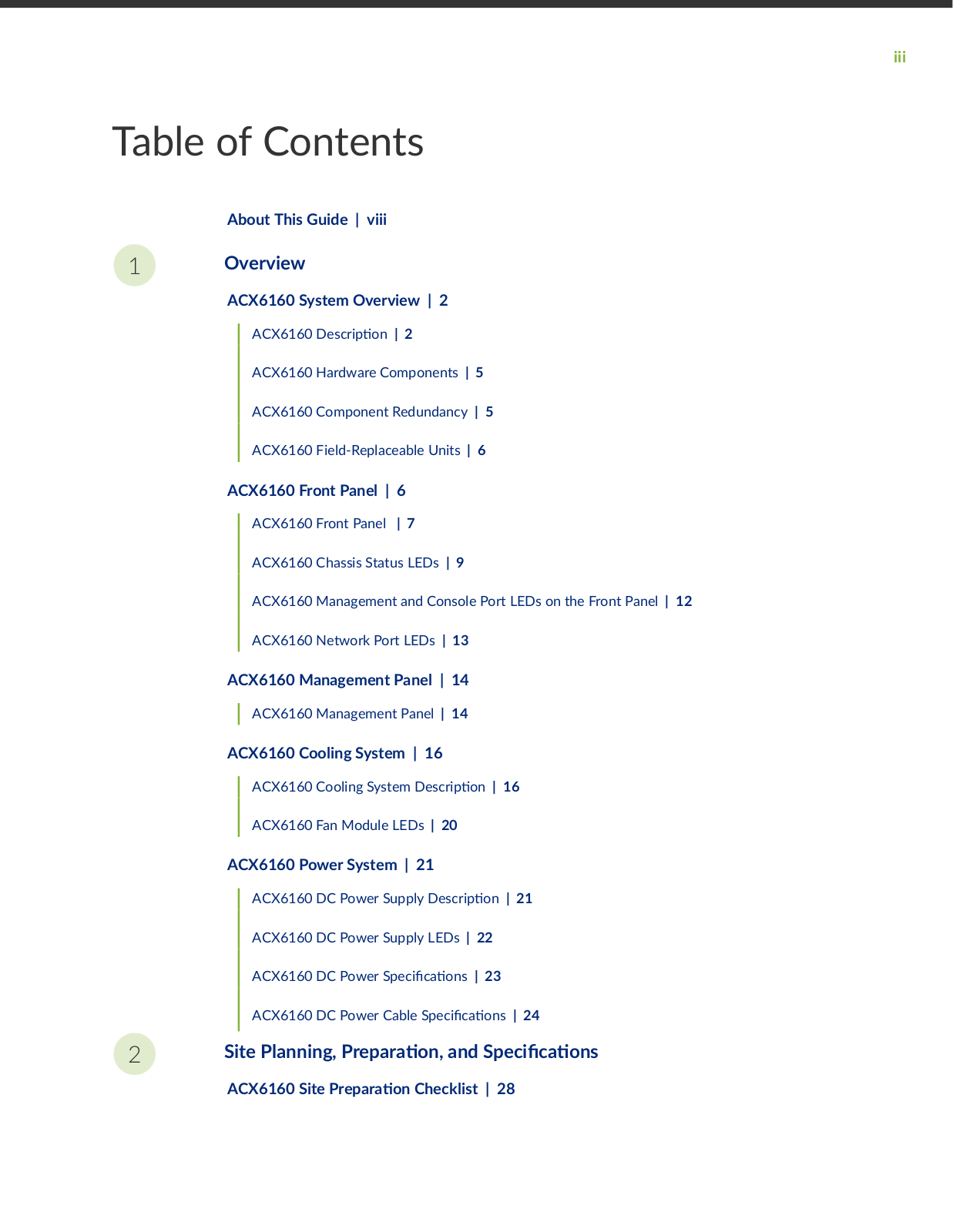
Table of Contents

1

2

About This Guide | viii

Overview

ACX6160 System Overview | 2

ACX6160 scr

n | 2

ACX6160 Hardware Components | 5

ACX6160 Component Redundancy | 5

ACX6160 Field-Replaceable Units | 6

ACX6160 Front Panel | 6

ACX6160 Front Panel | 7

ACX6160 Chassis Status LEDs | 9

ACX6160 Management and Console Port LEDs on the Front Panel | 12

ACX6160 Network Port LEDs | 13

ACX6160 Management Panel | 14

ACX6160 Management Panel | 14

ACX6160 Cooling System | 16


ACX6160 Cooling System


scr

n | 16


ACX6160 Fan Module LEDs | 20


ACX6160 Power System | 21


ACX6160 DC Power Supply

scr

n | 21


ACX6160 DC Power Supply LEDs | 22


ACX6160 DC Power S c

c

ns | 23


ACX6160 DC Power Cable S

c c

ns | 24


Site Planning, r

r

n and S c c

ns

ACX6160 Site r r n Checklist | 28

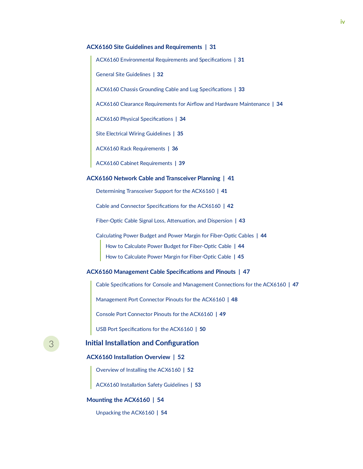
iv

ACX6160 Site Guidelines and Requirements | 31

ACX6160 Environmental Requirements and S

c

c

ns | 31

General Site Guidelines | 32


ACX6160 Chassis Grounding Cable and Lug S

c

c

ns | 33

ACX6160 Clearance Requirements for r w and Hardware Maintenance | 34

ACX6160 Physical S c c ns | 34

Site Electrical Wiring Guidelines | 35

ACX6160 Rack Requirements | 36

ACX6160 Cabinet Requirements | 39

ACX6160 Network Cable and Transceiver Planning | 41

Determining Transceiver Support for the ACX6160 | 41


Cable and Connector S c c

ns for the ACX6160 | 42


F b

r

c Cable Signal Loss,

n

n and Dispersion | 43


C

c

n

Power Budget and Power Margin for F b r

c Cables | 44


How to Calculate Power Budget for F b r

c Cable | 44


How to Calculate Power Margin for F b r

c Cable | 45


ACX6160 Management Cable S

c c

ns and Pinouts | 47


Cable S

c

c

ns for Console and Management C nn c

ns for the ACX6160 | 47


Management Port Connector Pinouts for the ACX6160 | 48


Console Port Connector Pinouts for the ACX6160 | 49


USB Port S

c

c ns for the ACX6160 | 50


3

n

ns


n and C n

r

n


ACX6160 ns


n Overview | 52


Overview of Installing the ACX6160 | 52


ACX6160 ns

n Safety Guidelines | 53


n n the ACX6160 | 54

Unpacking the ACX6160 | 54

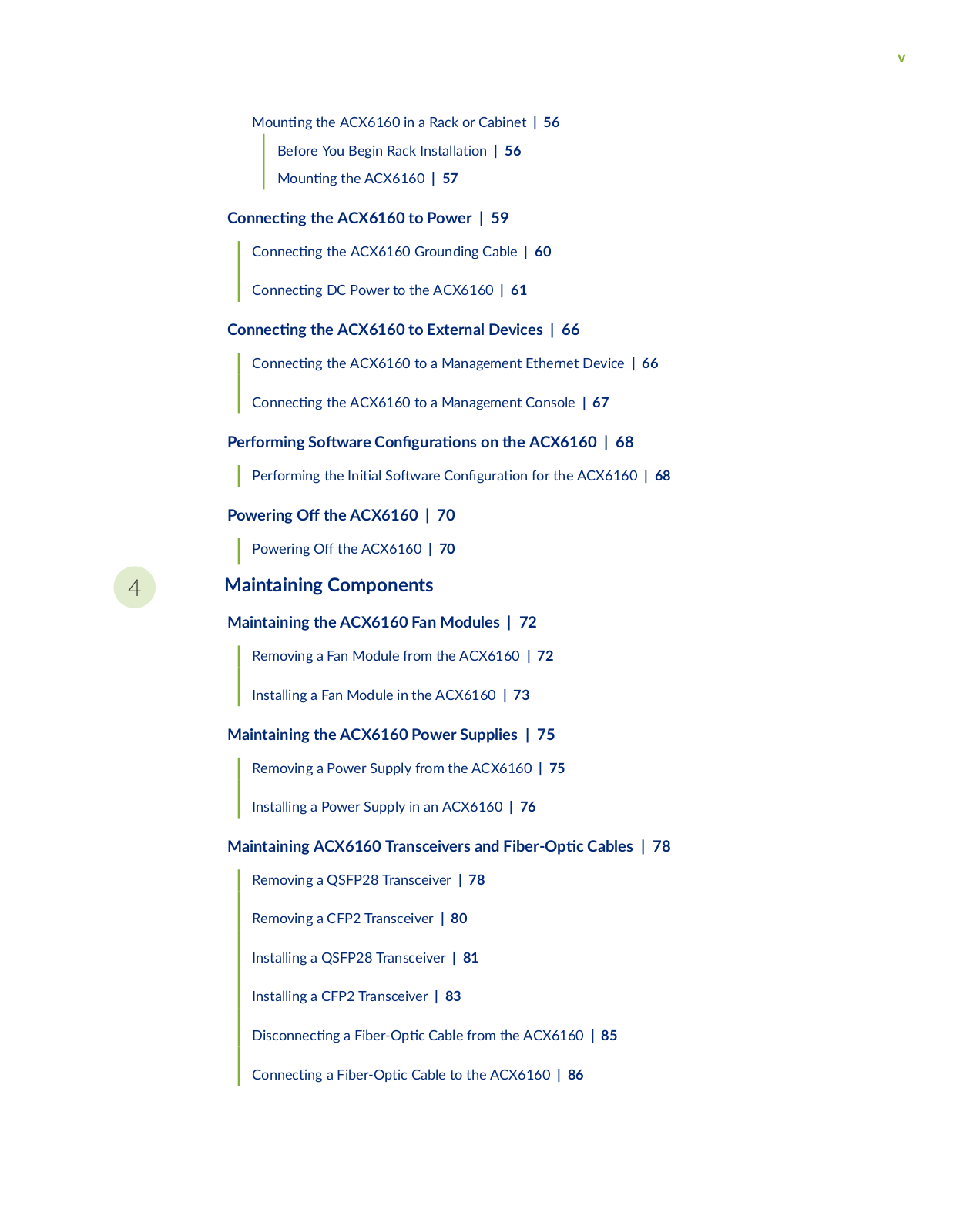
v

Mn n the ACX6160 in a Rack or Cabinet | 56

Before You Begin Rack ns

n | 56

M n n the ACX6160 | 57


C nn c n

the ACX6160 to Power | 59


C nn c

n

the ACX6160 Grounding Cable | 60


C nn c n

DC Power to the ACX6160 | 61

C nn c n

the ACX6160 to External Devices | 66


C nn c

n

the ACX6160 to a Management Ethernet Device | 66


C nn c

n

the ACX6160 to a Management Console | 67

Performing S

w r

C n

r

ns on the ACX6160 | 68


Performing the n

S

w r

C n r n for the ACX6160 | 68


Powering


the ACX6160 | 70


Powering

the ACX6160 | 70


4Maintaining Components

Maintaining the ACX6160 Fan Modules | 72

Removing a Fan Module from the ACX6160 | 72

Installing a Fan Module in the ACX6160 | 73

Maintaining the ACX6160 Power Supplies | 75

Removing a Power Supply from the ACX6160 | 75

Installing a Power Supply in an ACX6160 | 76

Maintaining ACX6160 Transceivers and b r

c Cables | 78


Removing a QSFP28 Transceiver | 78


Removing a CFP2 Transceiver | 80


Installing a QSFP28 Transceiver | 81


Installing a CFP2 Transceiver | 83


sc nn c

n a F b r

c Cable from the ACX6160 | 85


C nn c n

a F b r

c Cable to the ACX6160 | 86


5

6

7

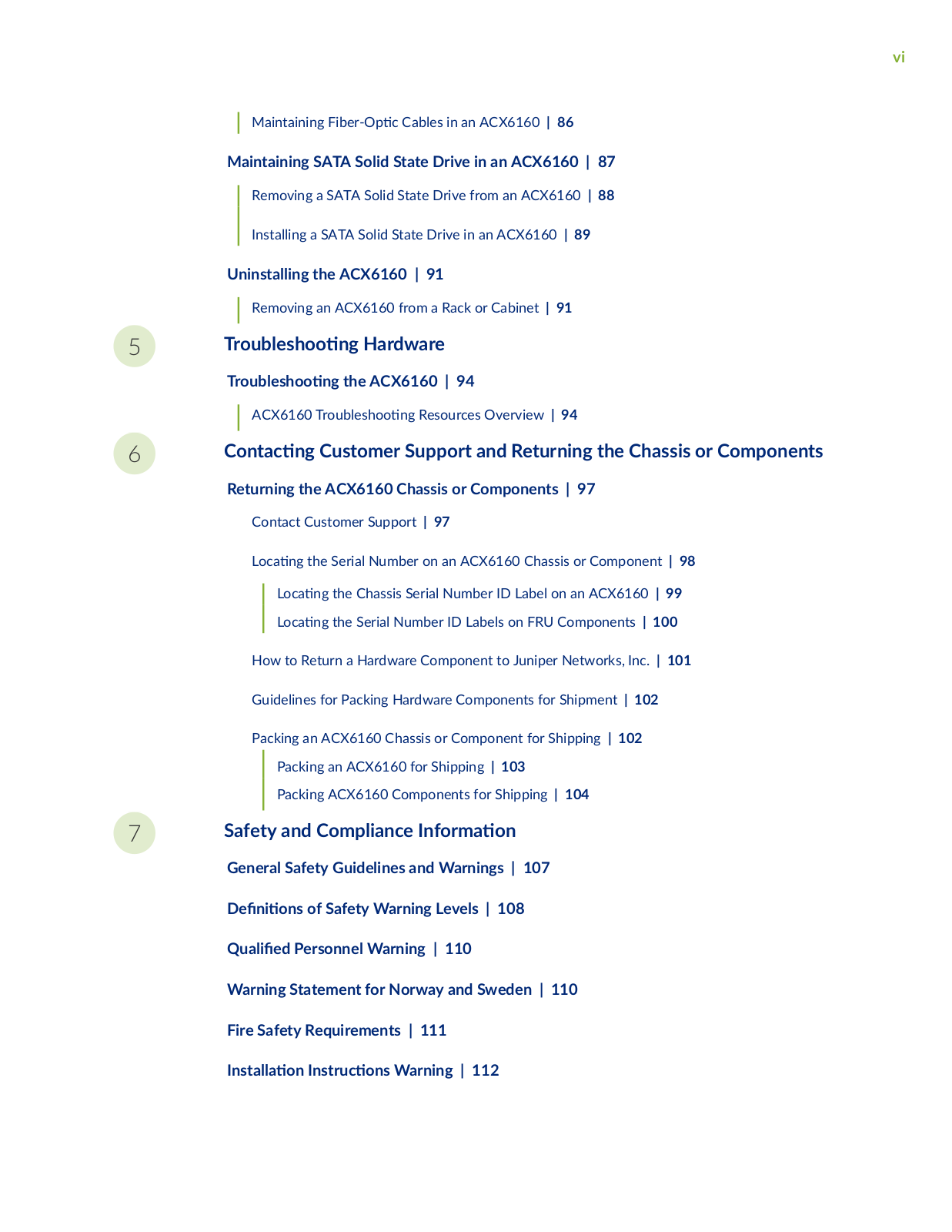
vi

Maintaining F b r c Cables in an ACX6160 | 86

Maintaining SATA Solid State Drive in an ACX6160 | 87

Removing a SATA Solid State Drive from an ACX6160 | 88

Installing a SATA Solid State Drive in an ACX6160 | 89

Uninstalling the ACX6160 | 91

Removing an ACX6160 from a Rack or Cabinet | 91

r b s n Hardware

rb s n the ACX6160 | 94


ACX6160

r b s

n Resources Overview | 94

C n c n

Customer Support and Returning the Chassis or Components

Returning the ACX6160 Chassis or Components | 97

Contact Customer Support | 97

L c n the Serial Number on an ACX6160 Chassis or Component | 98

L

c

n

the Chassis Serial Number ID Label on an ACX6160 | 99

L

c

n

the Serial Number ID Labels on FRU Components | 100

How to Return a Hardware Component to Juniper Networks, Inc. | 101

Guidelines for Packing Hardware Components for Shipment | 102

Packing an ACX6160 Chassis or Component for Shipping | 102

Packing an ACX6160 for Shipping | 103

Packing ACX6160 Components for Shipping | 104

Safety and Compliance n rm

n

General Safety Guidelines and Warnings | 107 n ns of Safety Warning Levels | 108

QPersonnel Warning | 110

Warning Statement for Norway and Sweden | 110

Fire Safety Requirements | 111

ns n ns r c ns Warning | 112

vii

Chassis and Component

n Guidelines | 113

Restricted Access Warning | 113

Ramp Warning | 115


R c

n n and C b n

n n Warnings | 115

Grounded Equipment Warning | 119

Laser and LED Safety Guidelines and Warnings | 120

Rn from Open Port Apertures Warning | 123

Maintenance and

r

n Safety Guidelines and Warnings | 124

General Electrical Safety Guidelines and Warnings | 130

c n to Take

r an Electrical Accident | 131

r v n n of c r s

c Discharge Damage | 132

DC Power Electrical Safety Guidelines | 133

DC Power Copper Conductors Warning | 134

DC Power sc nn c n Warning | 135

DC Power Grounding Requirements and Warning | 136

DC Power Wiring Sequence Warning | 137

DC Power Wiring

rm n

ns Warning | 139

Power Supplies

sc nn c n Warning | 140

TN Power Warning | 141

ACX6160 Regulatory Standard Compliances | 142

ACX6160 Regulatory Standard Compliances | 142

Compliance Statements for the ACX6160 Routers | 143

viii

About This Guide

Use this guide to plan, install, perform n

s

w r

c n r n perform r

n maintenance, and

to troubleshoot ACX6160 Universal Metro Routers.


r c m

n the ns

n and basic c

n

r

n procedures covered in this guide.

RELATED DOCUMENTATION

ACX6160 Quick Start Guide

1

CHAPTER

Overview

ACX6160 System Overview | 2

ACX6160 Front Panel | 6

ACX6160 Management Panel | 14

ACX6160 Cooling System | 16

ACX6160 Power System | 21

2

ACX6160 System Overview

IN THIS SECTION

ACX6160 scr

n | 2

ACX6160 Hardware Components | 5

ACX6160 Component Redundancy | 5

ACX6160 Field-Replaceable Units | 6

ACX6160 scr n

IN THIS SECTION

B n s of the ACX6160 | 3

Front Panel | 4

Rear Panel | 4

The Juniper Networks ACX6160 Universal Metro Router is a standalone c transponder that has 12 network ports, of which 8 are client ports, and 4 are line ports. It has removable DC power supplies and cooling fans. It supports the Open ROADM M S rc Agreements (MSA) (Version 2.2.1).

The ACX6160 is a transparent transponder that supports:


Eight 100-Gigabit Ethernet/OTU4 client interfaces that support QSFP28 LR4

cs


NOTE: Only four client interfaces are currently supported.


Four 100-Gbps coherent dense wavelength division m

x n (DWDM) line interfaces that


support CFP2-DCO

cs These interfaces

z quadrature phase s keying (QPSK) m

n

3

with Open ROADM (r c n r b

c add/drop m

x r) c m n high-gain forward error

c rr c n(HG F C)


Table 1 on page 3 describes the model.


Table 1: ACX6160 Hardware Model

Model Number

scr

n


ACX6160-T-DC

This model includes the chassis, v fan modules, and two DC power supplies.


B n

s of the ACX6160


The ACX6160 provides full Open ROADM c m

b

transponder support for metro packet

c


transport

c

ns in a 1 U

rm Open R


M c m

b APIs provide fully compliant


third-party controller support along with HG-FEC-compliant interfaces, enabling true interoperable


transponder

nc

n y


The ACX6160 supports a zero touch deployment (ZTD) feature that s n c n y reduces the

m


required to install and provision new equipment, r s

n in lower OpEx, lower TCO, and greater


r

n

c

ncy ZTD also reduces the complexity of deploying MPLS in the access layer.


• Disaggregated and open-line system—The ACX6160

m z s open-line system performance when


combined with disaggregated control design. This enables

x b updates with service c n n

y


and the freedom to deploy best transponder s

ns


4

Front Panel

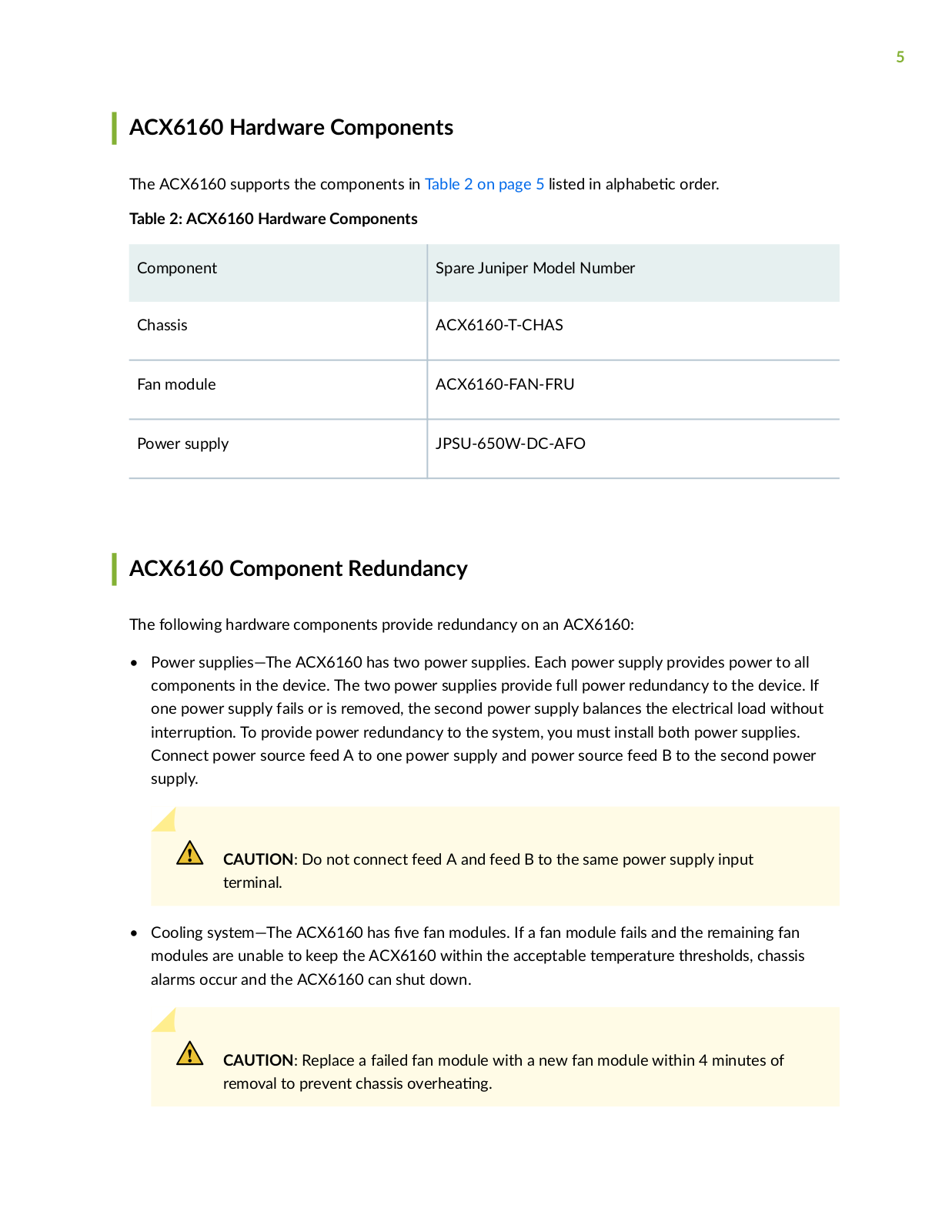
The front panel of the ACX6160 contains 12 network ports, comprising eight client ports and four line ports, LEDs, console and management ports, and system status LEDs. Figure 1 on page 4 shows the ACX6160 front panel.

Figure 1: ACX6160 Front Panel

1Status LEDs—Alarm (ALM), system (SYS),

4Line ports (CFP2 ports)

n c n (ID)


2Client ports (QSFP28 ports)

5RJ-45 console port labelled (CON)

3Pull-out tab with customer asset ID label

6RJ-45 (1000BASE-T) management Ethernet


port (labeled MGMT)


Rear Panel

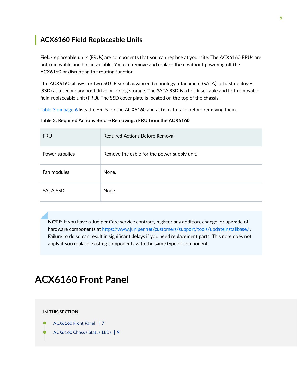
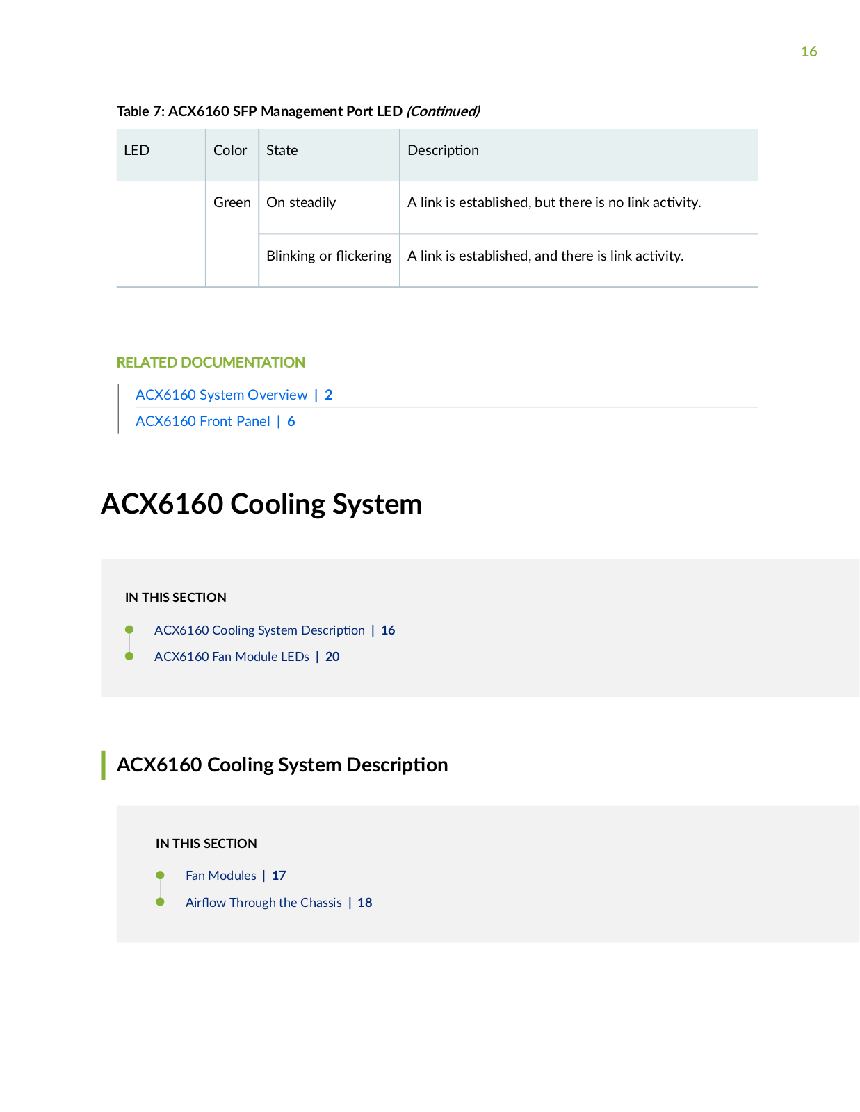
The rear panel contains the management panel, the fan modules, and power supplies for the ACX6160. Figure 2 on page 4 shows the ACX6160 rear panel with the management panel and the FRUs. The management panel has external clock sync r n z n ports, and a USB port to support s w r

ns n and recovery.

Figure 2: ACX6160 Management and FRU Panel

1

Management panel

3Power supplies (2)


2

Fan modules (5)


5

ACX6160 Hardware Components

The ACX6160 supports the components in Table 2 on page 5 listed in

b c order.

Table 2: ACX6160 Hardware Components


Component

Spare Juniper Model Number


Chassis

ACX6160-T-CHAS


Fan module

ACX6160-FAN-FRU


Power supply

JPSU-650W-DC-AFO


ACX6160 Component Redundancy

The following hardware components provide redundancy on an ACX6160:

Power supplies—The ACX6160 has two power supplies. Each power supply provides power to all components in the device. The two power supplies provide full power redundancy to the device. If one power supply fails or is removed, the second power supply balances the electrical load without

n rr n To provide power redundancy to the system, you must install both power supplies. Connect power source feed A to one power supply and power source feed B to the second power supply.

CAUTION: Do not connect feed A and feed B to the same power supply input terminal.

• Cooling system—The ACX6160 has v fan modules. If a fan module fails and the remaining fan modules are unable to keep the ACX6160 within the acceptable temperature thresholds, chassis alarms occur and the ACX6160 can shut down.

CAUTION: Replace a failed fan module with a new fan module within 4 minutes of removal to prevent chassis v r n

6

ACX6160 Field-Replaceable Units

Field-replaceable units (FRUs) are components that you can replace at your site. The ACX6160 FRUs are hot-removable and hot-insertable. You can remove and replace them without powering the

ACX6160 or sr n the r n nc n


The ACX6160 allows for two 50 GB serial advanced technology

c m n (SATA) solid state drives

(SSD) as a secondary boot drive or for log storage. The SATA SSD is a hot-insertable and hot-removable r c b unit (FRU). The SSD cover plate is located on the top of the chassis.

Table 3 on page 6 lists the FRUs for the ACX6160 and c ns to take before removing them.

Table 3: Required c

ns Before Removing a FRU from the ACX6160


FRU


Required c ns Before Removal


Power supplies


Remove the cable for the power supply unit.


Fan modules


None.


SATA SSD


None.


NOTE: If you have a Juniper Care service contract, register any


n change, or upgrade of

hardware components at

s

www

n r n c s m rs s

r

s

ns b s .

Failure to do so can result in s n

c n

delays if you need replacement parts. This note does not

apply if you replace x s n

components with the same type of component.


ACX6160 Front Panel

IN THIS SECTION

ACX6160 Front Panel | 7

ACX6160 Chassis Status LEDs | 9

7

ACX6160 Management and Console Port LEDs on the Front Panel | 12

ACX6160 Network Port LEDs | 13

ACX6160 Front Panel

IN THIS SECTION

QSFP28 Network Ports | 8

CFP2-DCO Network Ports | 8

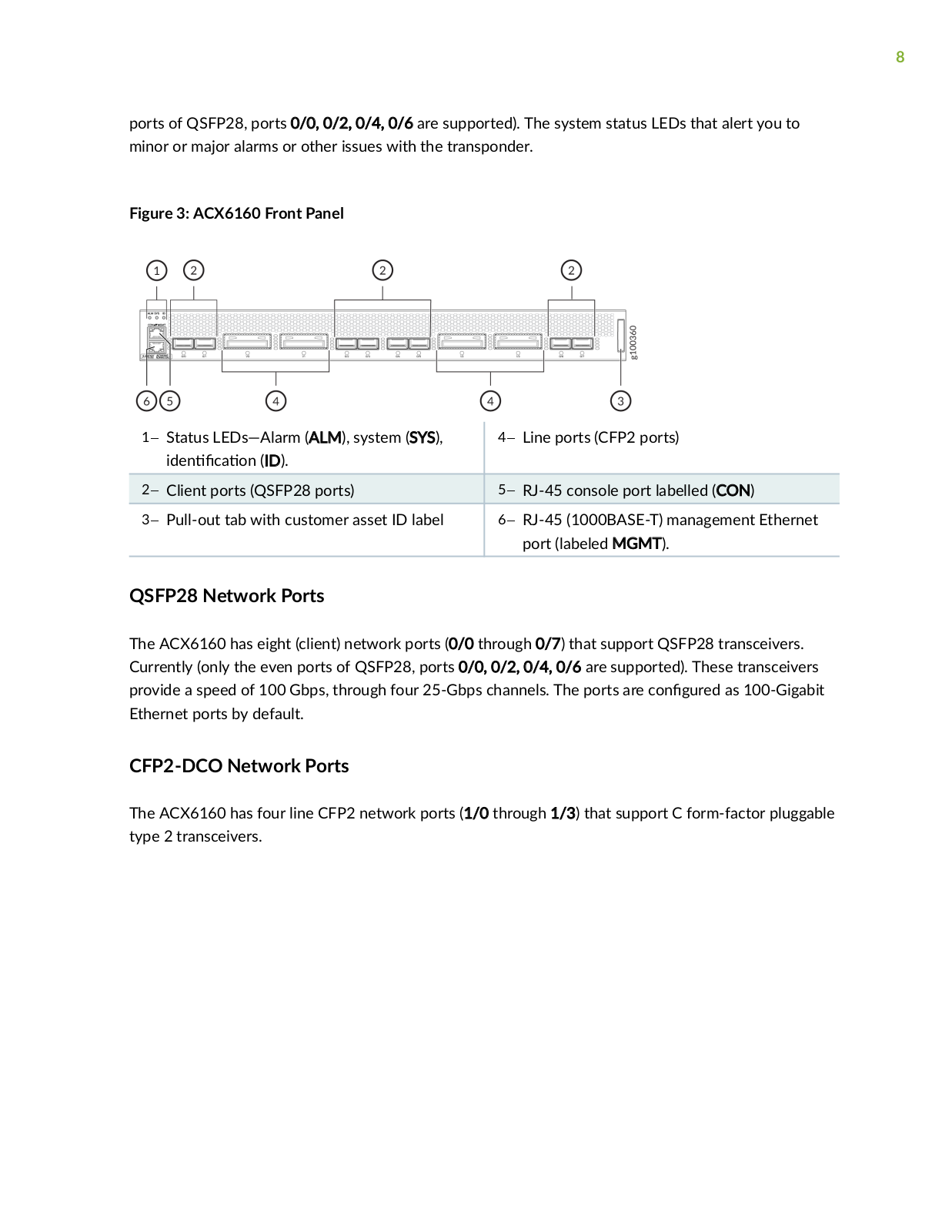
The front panel of the ACX6160 contains network ports, port LEDs, console and management ports, and system status LEDs. You can manage the ACX6160 by using an open ROADM controller. Figure 3 on page 8 shows the ACX6160 port panel. There are eight QSFP28 network ports and four line CFP2 ports on the front panel. Only four of the eight QSFP28 ports are currently supported (only the even

8

ports of QSFP28, ports 0/0, 0/2, 0/4, 0/6 are supported). The system status LEDs that alert you to minor or major alarms or other issues with the transponder.

Figure 3: ACX6160 Front Panel

1Status LEDs—Alarm (ALM), system (SYS),

4Line ports (CFP2 ports)

n c n (ID).


2Client ports (QSFP28 ports)

5RJ-45 console port labelled (CON)

3Pull-out tab with customer asset ID label

6RJ-45 (1000BASE-T) management Ethernet


port (labeled MGMT).


QSFP28 Network Ports

The ACX6160 has eight (client) network ports (0/0 through 0/7) that support QSFP28 transceivers. Currently (only the even ports of QSFP28, ports 0/0, 0/2, 0/4, 0/6 are supported). These transceivers provide a speed of 100 Gbps, through four 25-Gbps channels. The ports are c n r as 100-Gigabit Ethernet ports by default.

CFP2-DCO Network Ports

The ACX6160 has four line CFP2 network ports (1/0 through 1/3) that support C form-factor pluggable type 2 transceivers.

9

ACX6160 Chassis Status LEDs

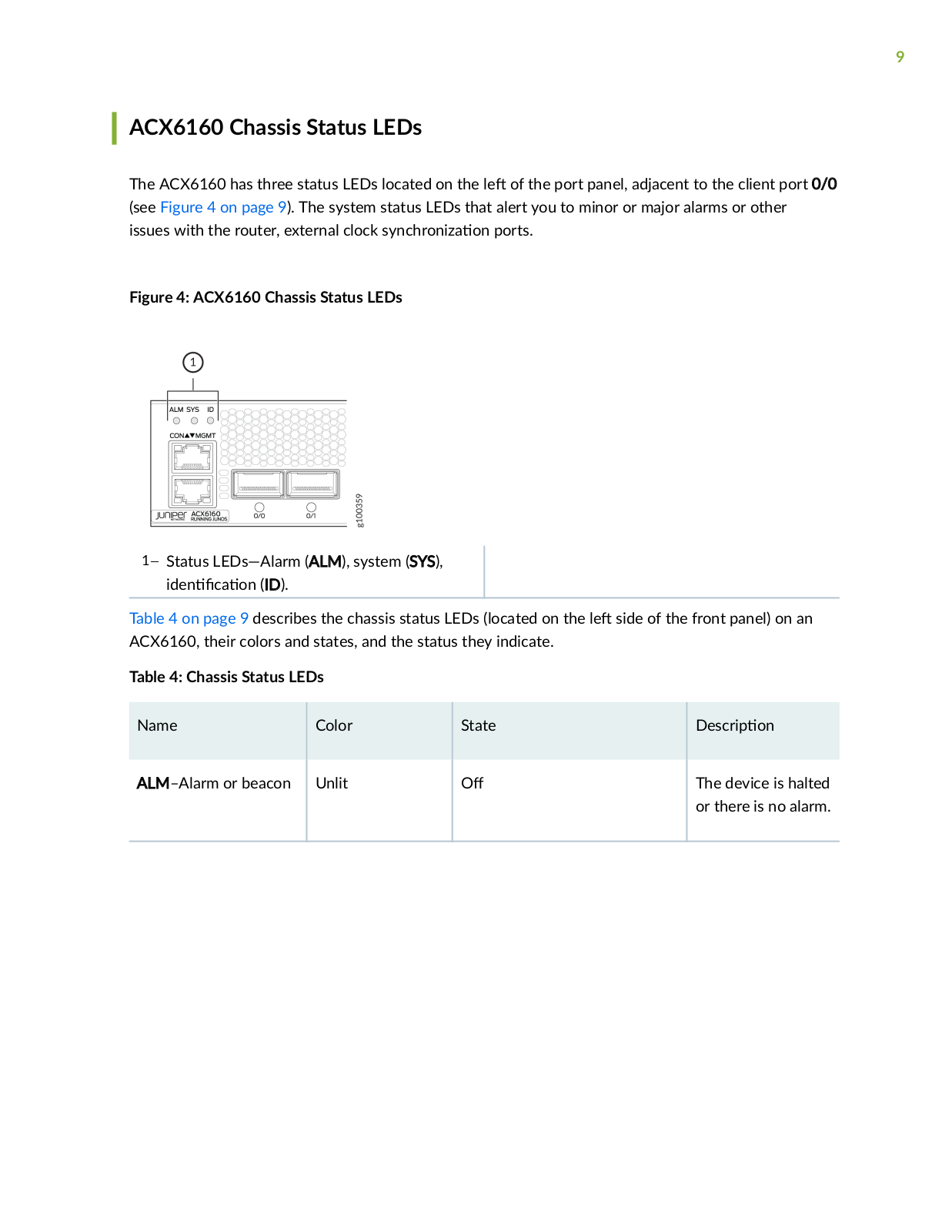
The ACX6160 has three status LEDs located on the

of the port panel, adjacent to the client port 0/0

(see Figure 4 on page 9). The system status LEDs that alert you to minor or major alarms or other

issues with the router, external clock sync r n z

n ports.

Figure 4: ACX6160 Chassis Status LEDs

1Status LEDs—Alarm (ALM), system (SYS), n c n (ID).

Table 4 on page 9 describes the chassis status LEDs (located on the

side of the front panel) on an

ACX6160, their colors and states, and the status they indicate.


Table 4: Chassis Status LEDs


Name

Color

State


scr

n


ALM–Alarm or beacon

Unlit


The device is halted


or there is no alarm.


10

Table 4: Chassis Status LEDs (C n n

)


Name

Color


State

scr

n


Red


On steadily

A major hardware


fault has occurred,


such as a


temperature alarm


or power failure,


and the device has


halted. When such


a fault occurs,


power

the


device. See


"Powering

the


ACX6160" on page


70. Correct any


voltage or site


temperature issues,


and allow the


device to cool


down. Power on


the device and


monitor the power


supply and fan


LEDs to help


determine where


the error is


occurring.


11

Table 4: Chassis Status LEDs (C n n

)


Name

Color


State

scr

n


Amber


On steadily

A minor alarm has


occurred, such as a


s w r

error.


When you see the


ALM LED lit amber,


power

the


device. "Powering


the ACX6160"


on page 70. Power


on the device and


monitor the SYS


status LEDs to


ensure that Junos


OS boots properly.


SYS–System

Unlit


The device is


powered

or


halted.


Green


On steadily

The device is


powered on and


Junos OS is loaded


on the device.


ID– n c n

Unlit


The beacon feature


is not enabled on


the device.


12

Table 4: Chassis Status LEDs (C n n

)


Name

Color


State

scr

n


Blue


Blinking

The beacon feature


is enabled on the


device. The beacon


feature helps the


administrator


n

y the device.


This feature is not


supported at this


m


ACX6160 Management and Console Port LEDs on the Front Panel

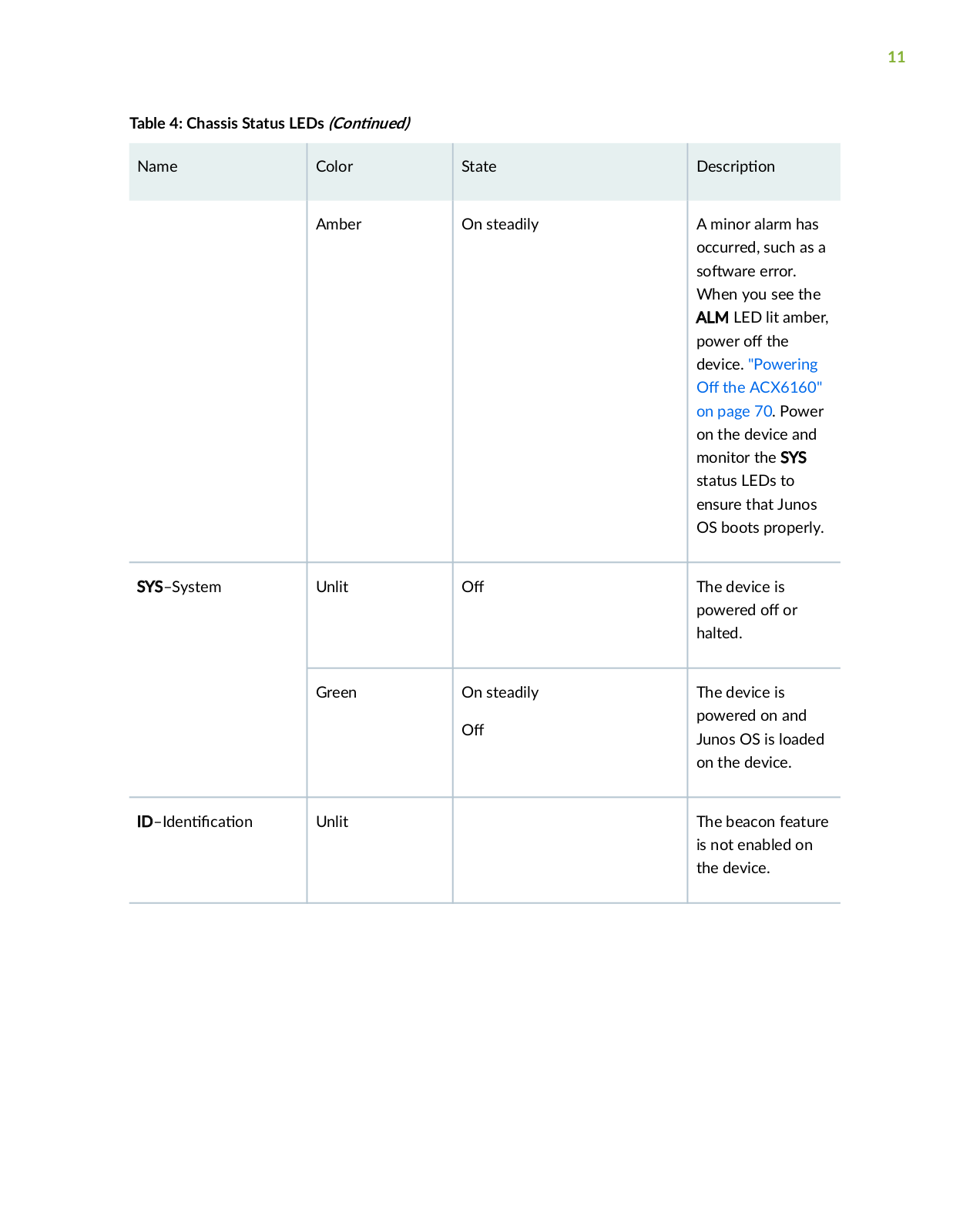
There are two management ports on the ACX6160, both ports are labeled MGMT. The RJ-45 management port is for 10/100/1000BASE-T c nn c ns and is located on the front panel. The other management port is located on the rear panel.

The RJ-45 port has separate LEDs for status and c v y Figure 5 on page 12 shows the c n of the LEDs.

Figure 5: Management Port LEDs on an ACX6160

1Status LED

2Link c v y LED


Table 5 on page 13 describes the RJ-45 management port LEDs.

13

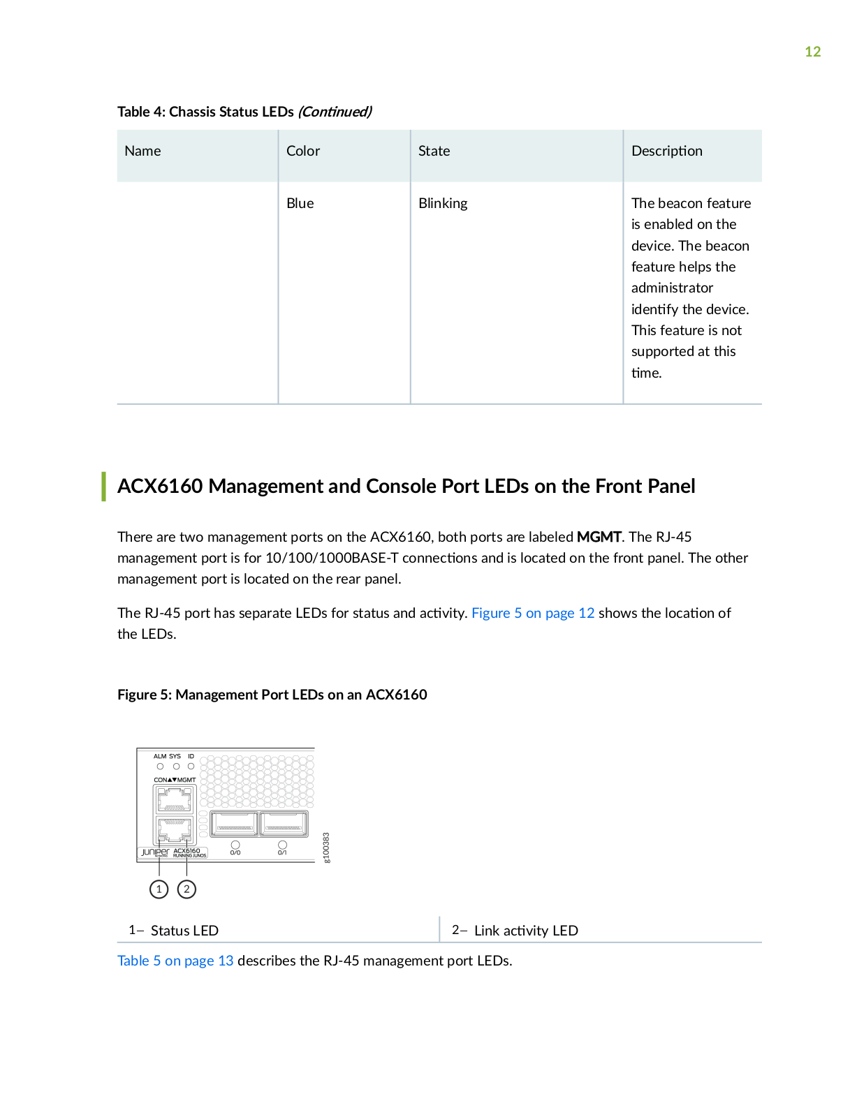
Table 5: ACX6160 RJ-45 Management Port LEDs


LED

Color

State

scr

n


Link c v y

Unlit


No link is established, there is a fault, or the link is


down.


Amber

Blinking or c r n

A link is established, and there is link c v y


Status

Unlit


Either the port speed is 10 Mbps or the link is down.


Green

On steadily

The port speed is 1000 Mbps.


ACX6160 Network Port LEDs

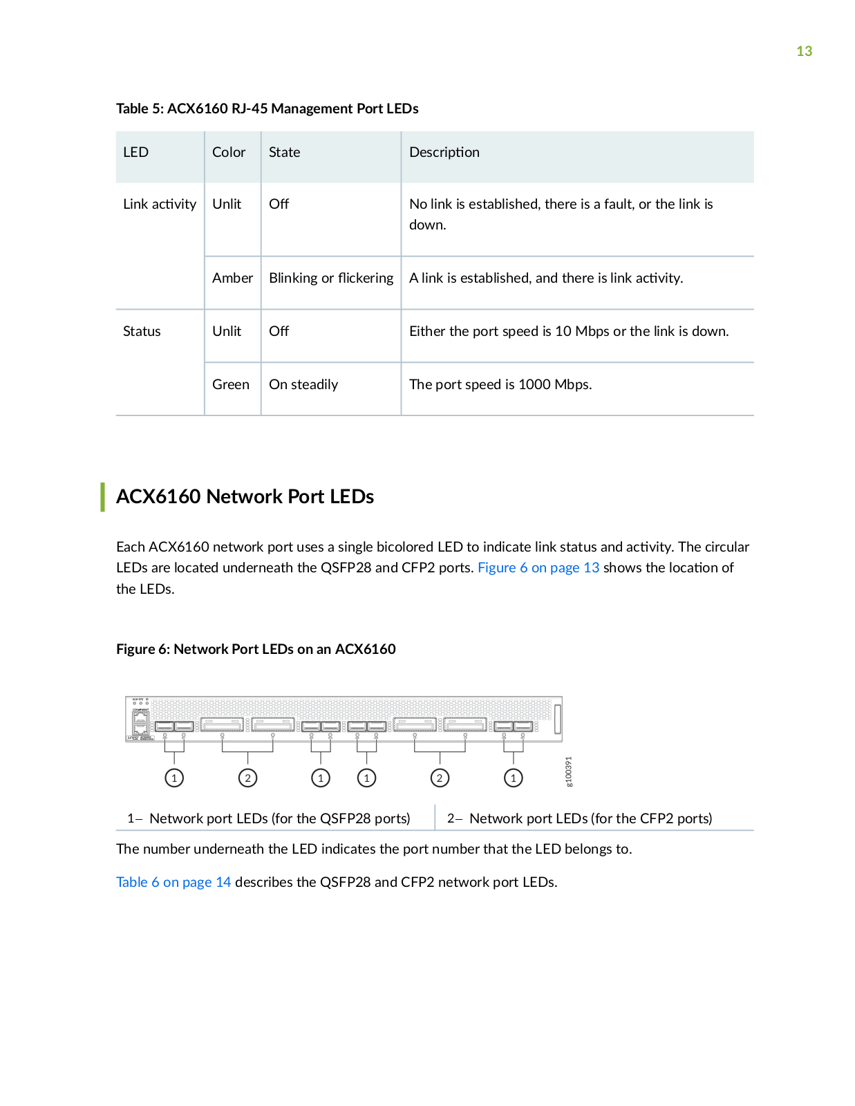
Each ACX6160 network port uses a single bicolored LED to indicate link status and c v y The circular LEDs are located underneath the QSFP28 and CFP2 ports. Figure 6 on page 13 shows the c n of the LEDs.

Figure 6: Network Port LEDs on an ACX6160

1Network port LEDs (for the QSFP28 ports)

2Network port LEDs (for the CFP2 ports)

The number underneath the LED indicates the port number that the LED belongs to.

Table 6 on page 14 describes the QSFP28 and CFP2 network port LEDs.

14

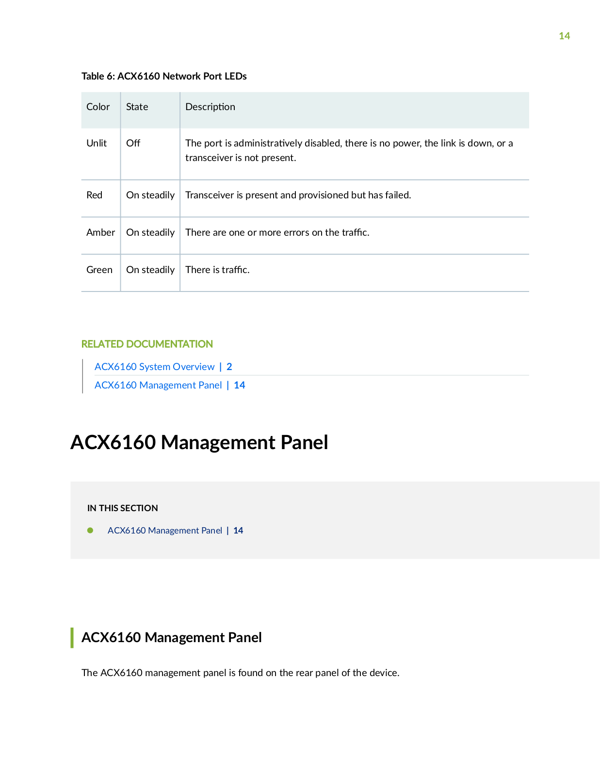
Table 6: ACX6160 Network Port LEDs

Color

State

scr

n


Unlit


The port is

m n s r v y disabled, there is no power, the link is down, or a


transceiver is not present.


Red

On steadily

Transceiver is present and provisioned but has failed.


Amber

On steadily

There are one or more errors on the r c


Green

On steadily

There is

r

c


RELATED DOCUMENTATION

ACX6160 System Overview | 2

ACX6160 Management Panel | 14

ACX6160 Management Panel

IN THIS SECTION

ACX6160 Management Panel | 14

ACX6160 Management Panel

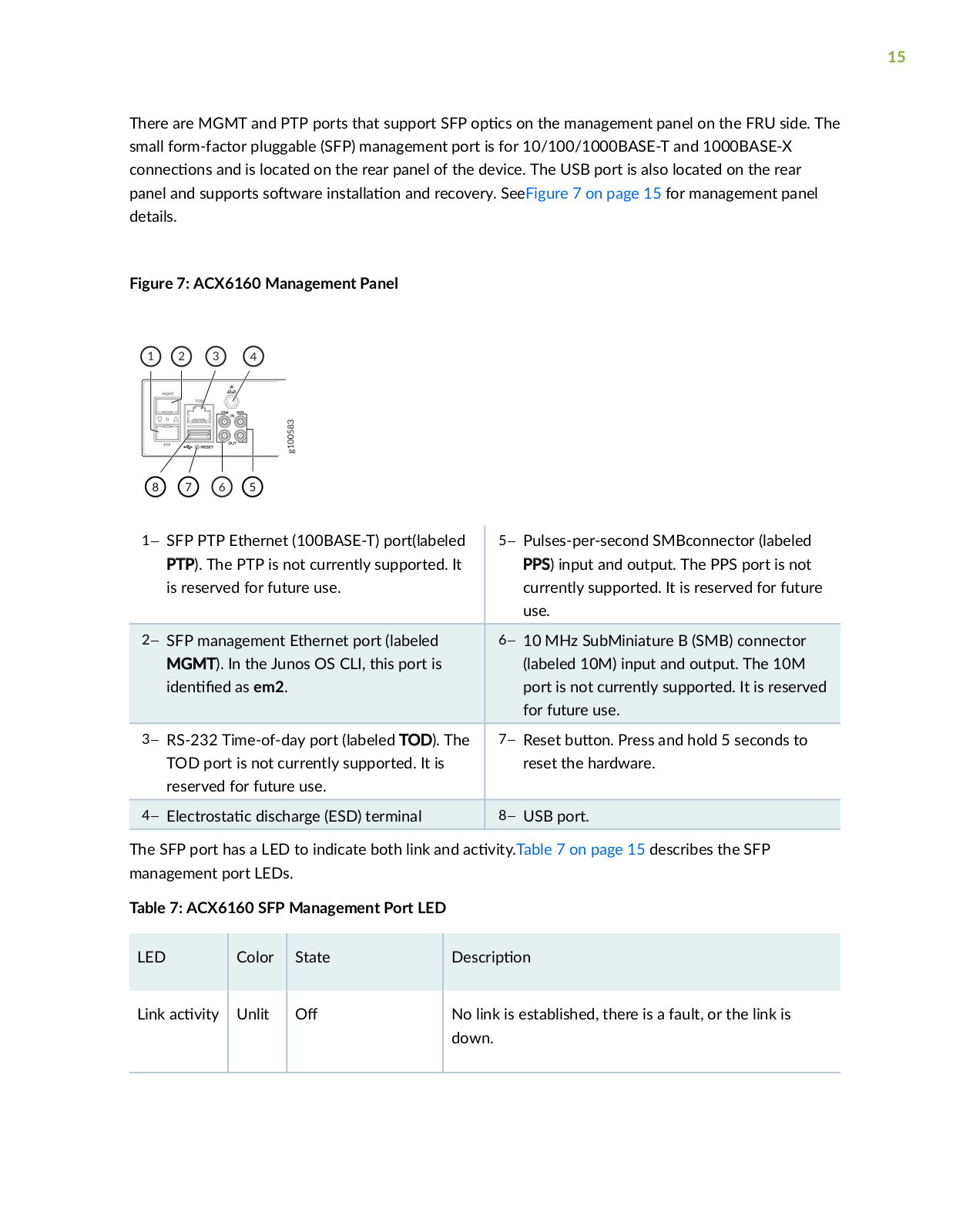
The ACX6160 management panel is found on the rear panel of the device.

15

There are MGMT and PTP ports that support SFP

cs on the management panel on the FRU side. The

small form-factor pluggable (SFP) management port is for 10/100/1000BASE-T and 1000BASE-X

c nn c ns and is located on the rear panel of the device. The USB port is also located on the rear

panel and supports s w r ns

n and recovery. SeeFigure 7 on page 15 for management panel

details.


Figure 7: ACX6160 Management Panel

1SFP PTP Ethernet (100BASE-T) port(labeled


5Pulses-per-second SMBconnector (labeled


PTP). The PTP is not currently supported. It


PPS) input and output. The PPS port is not


is reserved for future use.


currently supported. It is reserved for future


use.


2SFP management Ethernet port (labeled


610 MHz SubMiniature B (SMB) connector


MGMT). In the Junos OS CLI, this port is


(labeled 10M) input and output. The 10M


n

as em2.


port is not currently supported. It is reserved


for future use.

3RS-232 Time-of-day port (labeled TOD). The


7Reset b

n Press and hold 5 seconds to


TOD port is not currently supported. It is


reset the hardware.


reserved for future use.


4

c r s

c discharge (ESD) terminal


8USB port.


The SFP port has a LED to indicate both link and

c v

y Table 7 on page 15 describes the SFP

management port LEDs.


Table 7: ACX6160 SFP Management Port LED


LED


Color


State


scr

n


Link

c v y

Unlit


No link is established, there is a fault, or the link is


down.


16

Table

7: ACX6160 SFP Management Port LED (C n n

)


LED


Color

State

scr

n


Green

On steadily

A link is established, but there is no link

c

v y


Blinking or c r n

A link is established, and there is link c

v

y


RELATED DOCUMENTATION

ACX6160 System Overview | 2

ACX6160 Front Panel | 6

ACX6160 Cooling System

IN THIS SECTION

ACX6160 Cooling System scr

n | 16

ACX6160 Fan Module LEDs | 20

ACX6160 Cooling System scr

n

IN THIS SECTION

Fan Modules | 17

r w Through the Chassis | 18

Juniper ACX6160 User Manual

17

Fan Modules

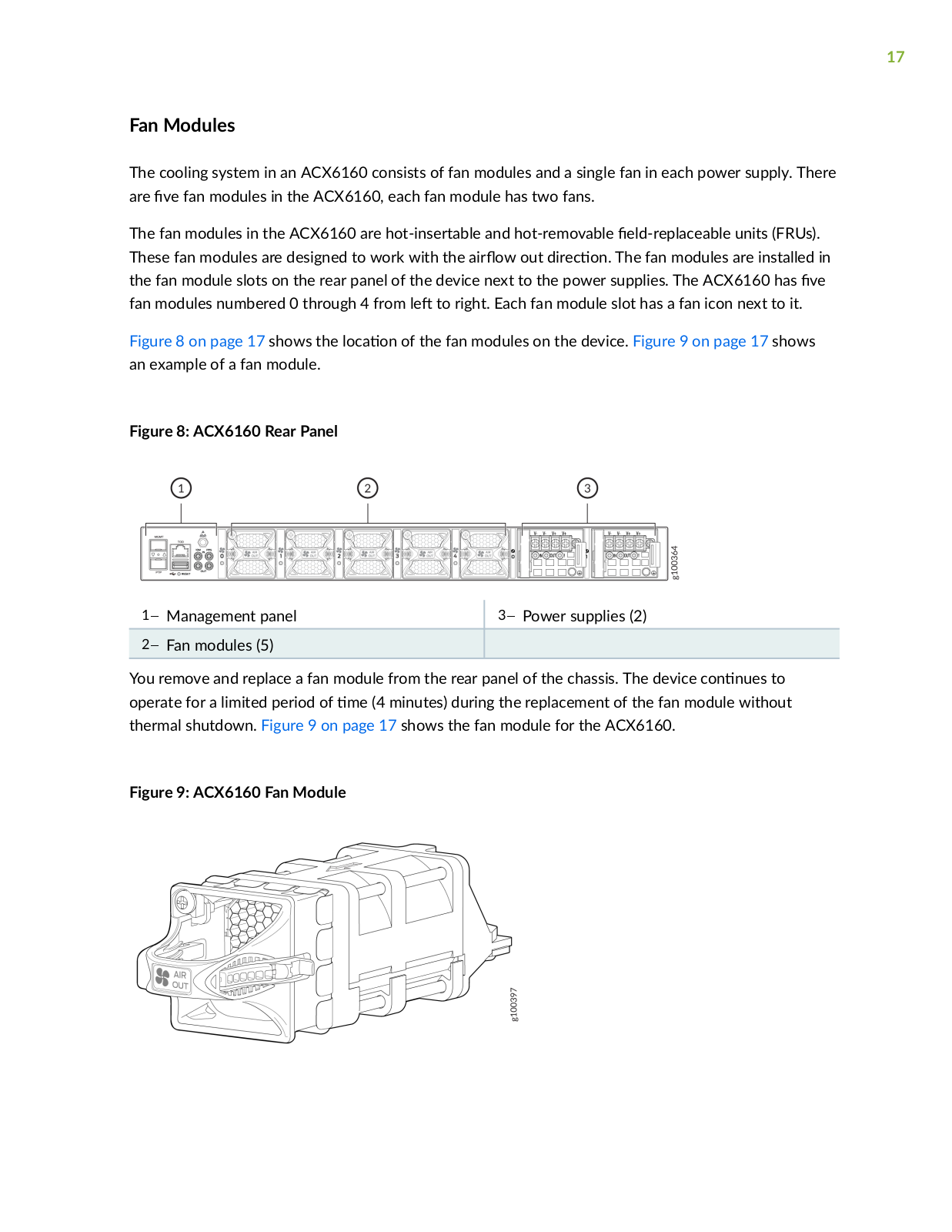
The cooling system in an ACX6160 consists of fan modules and a single fan in each power supply. There are v fan modules in the ACX6160, each fan module has two fans.

The fan modules in the ACX6160 are hot-insertable and hot-removable r c b units (FRUs). These fan modules are designed to work with the r w out r c n The fan modules are installed in the fan module slots on the rear panel of the device next to the power supplies. The ACX6160 has v fan modules numbered 0 through 4 from to right. Each fan module slot has a fan icon next to it.

Figure 8 on page 17 shows the c n of the fan modules on the device. Figure 9 on page 17 shows an example of a fan module.

Figure 8: ACX6160 Rear Panel

1

Management panel

3Power supplies (2)


2

Fan modules (5)


You remove and replace a fan module from the rear panel of the chassis. The device c n n s to operate for a limited period of m (4 minutes) during the replacement of the fan module without thermal shutdown. Figure 9 on page 17 shows the fan module for the ACX6160.

Figure 9: ACX6160 Fan Module

18

NOTE: All fan modules must be installed for

m

r n of the device.


Table 8 on page 18 lists the fan n rm

n


Table 8: ACX6160 Fan Module


Fan Module

Label on the Fan

r c n of

r

w in the Fan


Module

Module


ACX6160-FAN-

AIR OUT

Port-to-FRU, that is, air comes in

FRU


through vents on the end with


ports; air exhausts out the end


with the fans (also known as


front-to-back

r

w)


Power Supply to be Installed

You must install only power supplies that have AIR OUT labels in devices in which the fan modules have AIR OUT labels.

r w Through the Chassis

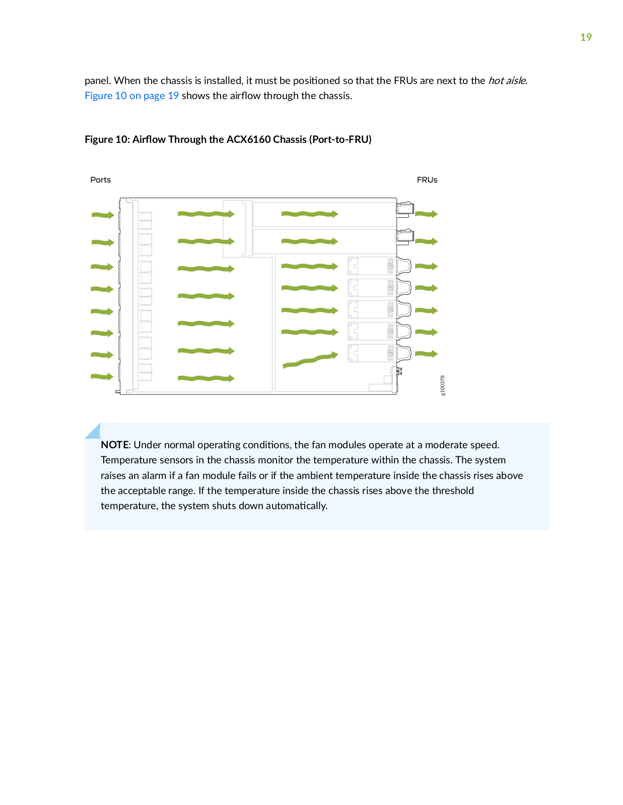
In the ACX6160 cooling system, cool air enters through the vents in the front panel and hot air exhausts

through the rear (FRU) panel. This type of

r w is known as r w out or port-to-FRU r w The

r w r c n on the ACX6160 is r

w out, air comes into the device through the vents in the front

19

panel. When the chassis is installed, it must be s n so that the FRUs are next to the hot aisle. Figure 10 on page 19 shows the r w through the chassis.

Figure 10: r w Through the ACX6160 Chassis (Port-to-FRU)

NOTE: Under normal r n c n ns the fan modules operate at a moderate speed. Temperature sensors in the chassis monitor the temperature within the chassis. The system raises an alarm if a fan module fails or if the ambient temperature inside the chassis rises above the acceptable range. If the temperature inside the chassis rises above the threshold temperature, the system shuts down m c y

20

ACX6160 Fan Module LEDs

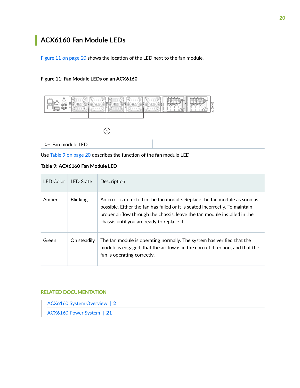
Figure 11 on page 20 shows the c n of the LED next to the fan module.

Figure 11: Fan Module LEDs on an ACX6160

1Fan module LED

Use Table 9 on page 20 describes the

nc

n of the fan module LED.


Table 9: ACX6160 Fan Module LED


LED Color

LED State

scr

n


Amber

Blinking

An error is detected in the fan module. Replace the fan module as soon as


possible. Either the fan has failed or it is seated incorrectly. To maintain


proper

r

w through the chassis, leave the fan module installed in the


chassis

n

you are ready to replace it.


Green

On steadily

The fan module is

r n

normally. The system has v r

that the


module is engaged, that the

r w is in the correct r c

n and that the


fan is

r

n

correctly.


RELATED DOCUMENTATION

ACX6160 System Overview | 2

ACX6160 Power System | 21

21

ACX6160 Power System

IN THIS SECTION


ACX6160 DC Power Supply

scr

n | 21


ACX6160 DC Power Supply LEDs | 22


ACX6160 DC Power S c c

ns | 23


ACX6160 DC Power Cable S

c c

ns | 24


ACX6160 DC Power Supply scr n

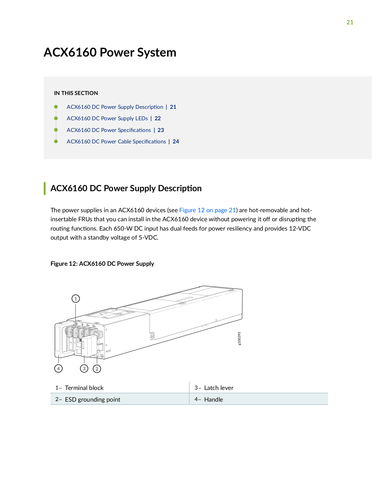
The power supplies in an ACX6160 devices (see Figure 12 on page 21) are hot-removable and hotinsertable FRUs that you can install in the ACX6160 device without powering it or sr n the r n nc ns Each 650-W DC input has dual feeds for power resiliency and provides 12-VDC output with a standby voltage of 5-VDC.

Figure 12: ACX6160 DC Power Supply

1

Terminal block

3

Latch lever


2

ESD grounding point

4

Handle


22

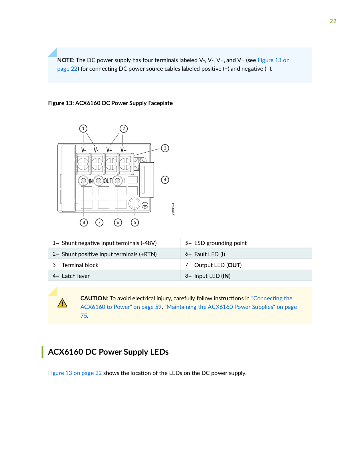
NOTE: The DC power supply has four terminals labeled V-, V-, V+, and V+ (see Figure 13 on page 22) for c nn c n DC power source cables labeled s v (+) and n v (–).

Figure 13: ACX6160 DC Power Supply Faceplate

1Shunt n

v

input terminals (-48V)

5ESD grounding point


2Shunt s

v

input terminals (+RTN)

6Fault LED (!)

3Terminal block


7Output LED (OUT)


4Latch lever


8Input LED (IN)


CAUTION: To avoid electrical injury, carefully follow ns r c ns in C nn c n the ACX6160 to Power" on page 59, "Maintaining the ACX6160 Power Supplies" on page 75.

ACX6160 DC Power Supply LEDs

Figure 13 on page 22 shows the c n of the LEDs on the DC power supply.

Loading...
+ 125 hidden pages