

Page 1

ACX5448, ACX5448-D, and ACX5448-M
Published
2019-12-23
Universal Metro Router Hardware Guide
Page 2

Juniper Networks, Inc.
1133 Innovation Way
Sunnyvale, California 94089
USA
408-745-2000
www.juniper.net
Juniper Networks, the Juniper Networks logo, Juniper, and Junos are registered trademarks of Juniper Networks, Inc. in
the United States and other countries. All other trademarks, service marks, registered marks, or registered service marks
are the property of their respective owners.
Juniper Networks assumes no responsibility for any inaccuracies in this document. Juniper Networks reserves the right
to change, modify, transfer, or otherwise revise this publication without notice.
ACX5448, ACX5448-D, and ACX5448-M Universal Metro Router Hardware Guide
Copyright © 2019 Juniper Networks, Inc. All rights reserved.
The information in this document is current as of the date on the title page.
ii
YEAR 2000 NOTICE
Juniper Networks hardware and software products are Year 2000 compliant. Junos OS has no known time-related
limitations through the year 2038. However, the NTP application is known to have some difficulty in the year 2036.
END USER LICENSE AGREEMENT
The Juniper Networks product that is the subject of this technical documentation consists of (or is intended for use with)
Juniper Networks software. Use of such software is subject to the terms and conditions of the End User License Agreement
(“EULA”) posted at https://support.juniper.net/support/eula/. By downloading, installing or using such software, you
agree to the terms and conditions of that EULA.
Page 3

Table of Contents
1
About the Documentation | ix
Documentation and Release Notes | ix
Using the Examples in This Manual | ix
Merging a Full Example | x
Merging a Snippet | xi
Documentation Conventions | xi
Documentation Feedback | xiv
Requesting Technical Support | xiv
Self-Help Online Tools and Resources | xv
Creating a Service Request with JTAC | xv
iii
Overview
ACX5448, ACX5448-D, and ACX5448-M System Overview | 19
ACX5400 Universal Metro Router Description | 19
Benefits of ACX5400 Routers | 21
ACX5448, ACX5448-D, and ACX5448-M System Overview | 21
ACX5400 Router Models | 25
Field-Replaceable Units in ACX5400 Routers | 26
Hardware Redundancy of ACX5400 Router Components and Functionality | 27
ACX5400 Routers Hardware and CLI Terminology Mapping | 27
ACX5400 System Software Overview | 29
ACX5448, ACX5448-D, and ACX5448-M Chassis | 30
Management Panel of ACX5400 Routers | 30
Port Panel of ACX5400 Routers | 32
Port Panel of an ACX5448 Router | 32
Port Panel of an ACX5448-D Router | 32
Port Panel of an ACX5448-M Router | 36
Chassis Status LEDs on ACX5400 Routers | 37
Management Port LEDs on ACX5400 Routers | 40
Network Port LEDs on ACX5400 Routers | 41
Page 4

Fan Status LEDs on ACX5400 Routers | 43
2
Power Supply LEDs on ACX5400 Routers | 44
AC Power Supply LEDs on ACX5400 Routers | 44
DC Power Supply LEDs on ACX5400 Routers | 46
Cooling System and Airflow in ACX5448, ACX5448-D, and ACX5448-M Routers | 47
Fan Modules | 48
Fan Module and Power Supply Requirement | 50
Fan Module Status | 51
ACX5448, ACX5448-D, and ACX5448-M Power System | 52
AC Power Supply for ACX5400 Routers | 53
AC Power Specifications for ACX5400 Routers | 55
AC Power Cord Specifications for ACX5400 Routers | 55
DC Power Supply for ACX5400 Routers | 57
iv
DC Power Specifications for ACX5400 Routers | 59
Site Planning, Preparation, and Specifications
Site Preparation Checklist for ACX5448, ACX5448-D, and ACX5448-M Routers | 63
ACX5448, ACX5448-D, and ACX5448-M Site Guidelines and Requirements | 64
General Site Guidelines | 65
Site Electrical Wiring Guidelines | 65
Chassis Physical Specifications for ACX5400 Routers | 66
ACX5400 Router Environmental Requirements and Specifications | 67
ACX5400 Grounding Cable and Lug Specifications | 68
Clearance Requirements for Airflow and Hardware Maintenance for ACX5400 Routers | 70
Cabinet Requirements for ACX5400 Routers | 71
Page 5

Rack Requirements for ACX5400 Routers | 72
3
ACX5448, ACX5448-D, and ACX5448-M Network Cable and Transceiver Planning | 73
Determining Transceiver Support for ACX5400 | 74
Cable Specifications for QSFP+ and QSFP28 Transceivers | 74
Calculating Power Budget and Power Margin for Fiber-Optic Cables | 76
Calculating Power Budget for Fiber-Optic Cable | 76
Calculating Power Margin for Fiber-Optic Cable | 77
Understanding Fiber-Optic Cable Signal Loss, Attenuation, and Dispersion | 78
Signal Loss in Multimode and Single-Mode Fiber-Optic Cable | 78
Attenuation and Dispersion in Fiber-Optic Cable | 79
ACX5448, ACX5448-D, and ACX5448-M Management and Console Port Specifications
and Pinouts | 80
Management Cable Specifications for ACX5400 Routers | 80
v
Management Port Connector Pinout Information for ACX Series Routers | 80
Console or Auxiliary Port Connector Pinout on ACX Series Routers | 81
USB Port Specifications for an ACX Series Router | 82
Initial Installation and Configuration
ACX5448, ACX5448-D, and ACX5448-M Installation Overview | 85
Unpacking and Mounting ACX5448, ACX5448-D, and ACX5448-M | 86
Unpack an ACX5400 Router | 86
Mount an ACX5400 Router in a Rack or Cabinet | 87
Before You Begin Rack Installation | 88
Install the ACX5400 Router in the Rack | 89
Connect ACX5448, ACX5448-D, and ACX5448-M to Power | 95
Connect Earth Ground to ACX5400 Routers | 95
Connect AC Power to an ACX5400 Router | 98
Connect DC Power to an ACX5400 Router | 102
Connect ACX5448, ACX5448-D, and ACX5448-M to External Devices | 106
Connect an ACX5400 Router to a Management Console | 106
Connect an ACX5400 Router to a Network for Out-of-Band Management | 107
Page 6

Connect an ACX5400 Router to External Clocking and Timing Devices | 108
4
5
Perform Initial Software Configuration for the ACX5448, ACX5448-D, and ACX5448-M
Routers | 109
Maintaining Components
Maintaining ACX5448, ACX5448-D, and ACX5448-M Components | 115
Replace an ACX5400 Fan Module | 115
Remove a Fan Module from an ACX5400 Router | 115
Install a Fan Module in an ACX5400 Router | 117
Replace an ACX5400 AC Power Supply Module | 118
Remove an AC Power Supply Module from an ACX5400 Router | 118
Install an AC Power Supply Module in an ACX5400 Router | 120
Replace an ACX5400 DC Power Supply Module | 122
Remove an ACX5400 DC Power Supply Module | 123
vi
Install an ACX5400 DC Power Supply Module | 124
Replace an SFP+ Transceiver | 127
Remove an SFP+ Transceiver | 127
Install an SFP+ Transceiver | 128
Replace a QSFP28 Transceiver | 129
Remove a QSFP28 Transceiver | 130
Install a QSFP28 Transceiver | 131
Replacing a CFP2 Transceiver | 132
Removing a CFP2 Transceiver | 133
Installing a CFP2 Transceiver | 134
Maintaining Fiber-Optic Cables | 136
Removing the ACX5448, ACX5448-D, or ACX5448-M Router | 136
Power Off an ACX5400 Router | 137
Remove an ACX5400 Router from a Rack or Cabinet | 138
Troubleshooting Hardware
Troubleshooting the ACX5448, ACX5448-D, and ACX5448-M Routers | 143
Alarm Types and Severity Classes on ACX Series Routers | 143
Alarm Types | 143
Alarm Severity Classes | 144
Page 7

Contacting Customer Support and Returning the Chassis or Components
6
7
Contacting Customer Support and Returning the Chassis or Components | 147
Returning a Hardware Component to Juniper Networks, Inc. | 147
How to Locate the Serial Number on an ACX5400 Router or Component | 148
List the Chassis and Component Details Using the CLI | 149
Locate the Chassis Serial Number ID Label on an ACX5400 Router | 151
Locate the Serial Number ID Labels on ACX5400 Power Supply Modules | 152
Locate the Serial Number ID Label on an ACX5400 Fan Module | 153
Contacting Customer Support to Obtain Return Material Authorization | 154
Guidelines for Packing Hardware Components for Shipment | 155
Safety and Compliance Information
General Safety Guidelines and Warnings | 159
vii
Definitions of Safety Warning Levels | 160
Qualified Personnel Warning | 163
Warning Statement for Norway and Sweden | 164
Fire Safety Requirements | 164
Fire Suppression | 164
Fire Suppression Equipment | 164
Installation Instructions Warning | 166
Restricted Access Warning | 167
Ramp Warning | 169
Rack-Mounting and Cabinet-Mounting Warnings | 170
Grounded Equipment Warning | 176
Radiation from Open Port Apertures Warning | 177
Laser and LED Safety Guidelines and Warnings | 178
General Laser Safety Guidelines | 178
Class 1 Laser Product Warning | 179
Class 1 LED Product Warning | 180
Page 8

Laser Beam Warning | 181
Maintenance and Operational Safety Guidelines and Warnings | 181
Battery Handling Warning | 183
Jewelry Removal Warning | 184
Lightning Activity Warning | 186
Operating Temperature Warning | 187
Product Disposal Warning | 189
General Electrical Safety Guidelines and Warnings | 190
Prevention of Electrostatic Discharge Damage | 191
Site Electrical Wiring Guidelines | 192
AC Power Electrical Safety Guidelines | 193
viii
AC Power Disconnection Warning | 195
DC Power Disconnection Warning | 196
DC Power Grounding Requirements and Warning | 198
DC Power Wiring Sequence Warning | 200
DC Power Wiring Terminations Warning | 203
Multiple Power Supplies Disconnection Warning | 206
TN Power Warning | 207
Action to Take After an Electrical Accident | 207
Agency Approvals for ACX5448, ACX5448-D, and ACX5448-M Routers | 208
Compliance Statements for NEBS | 209
Compliance Statements for EMC Requirements | 209
Canada | 209
European Community | 210
Israel | 210
Japan | 210
United States | 210
Compliance Statements for Environmental Requirements | 211
Page 9
About the Documentation
IN THIS SECTION
Documentation and Release Notes | ix
Using the Examples in This Manual | ix
Documentation Conventions | xi
Documentation Feedback | xiv
Requesting Technical Support | xiv
Use this guide to install hardware and perform initial software configuration, routine maintenance, and
troubleshooting for the ACX5448 Router.
ix
After completing the installation and basic configuration procedures covered in this guide, refer to the
Junos OS documentation for information about further software configuration.
Documentation and Release Notes
To obtain the most current version of all Juniper Networks®technical documentation, see the product
documentation page on the Juniper Networks website at https://www.juniper.net/documentation/.
If the information in the latest release notes differs from the information in the documentation, follow the
product Release Notes.
Juniper Networks Books publishes books by Juniper Networks engineers and subject matter experts.
These books go beyond the technical documentation to explore the nuances of network architecture,
deployment, and administration. The current list can be viewed at https://www.juniper.net/books.
Using the Examples in This Manual
If you want to use the examples in this manual, you can use the load merge or the load merge relative
command. These commands cause the software to merge the incoming configuration into the current
candidate configuration. The example does not become active until you commit the candidate configuration.
Page 10

If the example configuration contains the top level of the hierarchy (or multiple hierarchies), the example
is a full example. In this case, use the load merge command.
If the example configuration does not start at the top level of the hierarchy, the example is a snippet. In
this case, use the load merge relative command. These procedures are described in the following sections.
Merging a Full Example
To merge a full example, follow these steps:
1. From the HTML or PDF version of the manual, copy a configuration example into a text file, save the
file with a name, and copy the file to a directory on your routing platform.
For example, copy the following configuration to a file and name the file ex-script.conf. Copy the
ex-script.conf file to the /var/tmp directory on your routing platform.
system {
scripts {
commit {
file ex-script.xsl;
}
}
}
interfaces {
fxp0 {
disable;
unit 0 {
family inet {
address 10.0.0.1/24;
}
}
}
}
x
2. Merge the contents of the file into your routing platform configuration by issuing the load merge
configuration mode command:
[edit]
user@host# load merge /var/tmp/ex-script.conf
load complete
Page 11

Merging a Snippet
To merge a snippet, follow these steps:
1. From the HTML or PDF version of the manual, copy a configuration snippet into a text file, save the
file with a name, and copy the file to a directory on your routing platform.
For example, copy the following snippet to a file and name the file ex-script-snippet.conf. Copy the
ex-script-snippet.conf file to the /var/tmp directory on your routing platform.
commit {
file ex-script-snippet.xsl; }
2. Move to the hierarchy level that is relevant for this snippet by issuing the following configuration mode
command:
[edit]
user@host# edit system scripts
[edit system scripts]
xi
3. Merge the contents of the file into your routing platform configuration by issuing the load merge
relative configuration mode command:
[edit system scripts]
user@host# load merge relative /var/tmp/ex-script-snippet.conf
load complete
For more information about the load command, see CLI Explorer.
Documentation Conventions
Table 1 on page xii defines notice icons used in this guide.
Page 12
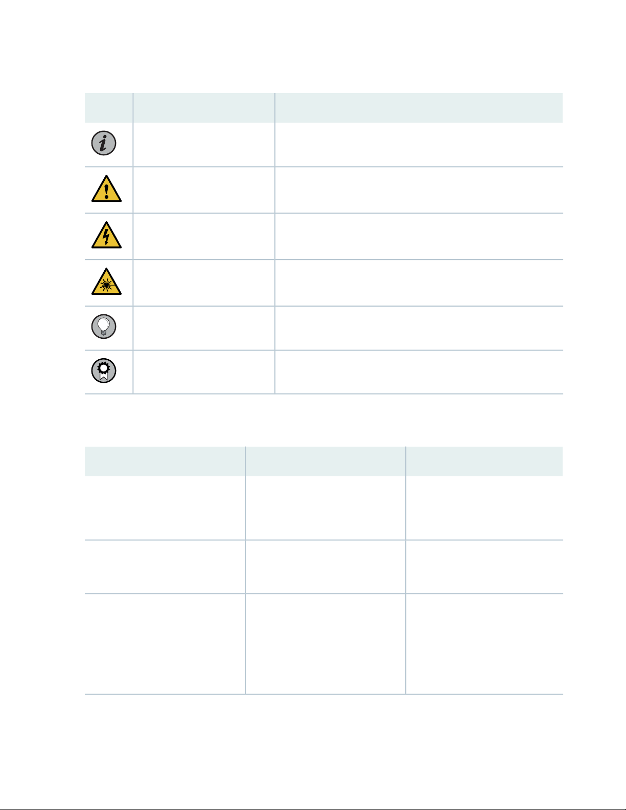
Table 1: Notice Icons
xii
DescriptionMeaningIcon
Indicates important features or instructions.Informational note
Caution
Indicates a situation that might result in loss of data or hardware
damage.
Alerts you to the risk of personal injury or death.Warning
Alerts you to the risk of personal injury from a laser.Laser warning
Indicates helpful information.Tip
Alerts you to a recommended use or implementation.Best practice
Table 2 on page xii defines the text and syntax conventions used in this guide.
Table 2: Text and Syntax Conventions
ExamplesDescriptionConvention
Fixed-width text like this
Italic text like this
Represents text that you type.Bold text like this
Represents output that appears on
the terminal screen.
Introduces or emphasizes important
•
new terms.
Identifies guide names.
•
Identifies RFC and Internet draft
•
titles.
To enter configuration mode, type
the configure command:
user@host> configure
user@host> show chassis alarms
No alarms currently active
A policy term is a named structure
•
that defines match conditions and
actions.
Junos OS CLI User Guide
•
RFC 1997, BGP Communities
•
Attribute
Page 13

Table 2: Text and Syntax Conventions (continued)
xiii
ExamplesDescriptionConvention
Italic text like this
Text like this
< > (angle brackets)
| (pipe symbol)
Represents variables (options for
which you substitute a value) in
commands or configuration
statements.
Represents names of configuration
statements, commands, files, and
directories; configuration hierarchy
levels; or labels on routing platform
components.
variables.
Indicates a choice between the
mutually exclusive keywords or
variables on either side of the symbol.
The set of choices is often enclosed
in parentheses for clarity.
Configure the machine’s domain
name:
[edit]
root@# set system domain-name
domain-name
To configure a stub area, include
•
the stub statement at the [edit
protocols ospf area area-id]
hierarchy level.
The console port is labeled
•
CONSOLE.
stub <default-metric metric>;Encloses optional keywords or
broadcast | multicast
(string1 | string2 | string3)
# (pound sign)
[ ] (square brackets)
Indention and braces ( { } )
; (semicolon)
GUI Conventions
Indicates a comment specified on the
same line as the configuration
statement to which it applies.
Encloses a variable for which you can
substitute one or more values.
Identifies a level in the configuration
hierarchy.
Identifies a leaf statement at a
configuration hierarchy level.
rsvp { # Required for dynamic MPLS
only
community name members [
community-ids ]
[edit]
routing-options {
static {
route default {
nexthop address;
retain;
}
}
}
Page 14
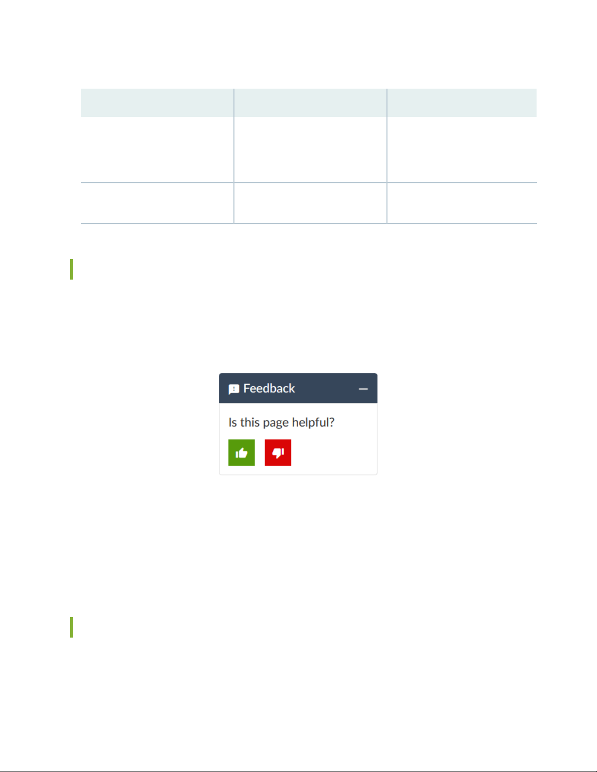
Table 2: Text and Syntax Conventions (continued)
xiv
ExamplesDescriptionConvention
Bold text like this
> (bold right angle bracket)
Represents graphical user interface
(GUI) items you click or select.
Separates levels in a hierarchy of
menu selections.
In the Logical Interfaces box, select
•
All Interfaces.
To cancel the configuration, click
•
Cancel.
In the configuration editor hierarchy,
select Protocols>Ospf.
Documentation Feedback
We encourage you to provide feedback so that we can improve our documentation. You can use either
of the following methods:
Online feedback system—Click TechLibrary Feedback, on the lower right of any page on the Juniper
•
Networks TechLibrary site, and do one of the following:
Click the thumbs-up icon if the information on the page was helpful to you.
•
Click the thumbs-down icon if the information on the page was not helpful to you or if you have
•
suggestions for improvement, and use the pop-up form to provide feedback.
E-mail—Send your comments to techpubs-comments@juniper.net. Include the document or topic name,
•
URL or page number, and software version (if applicable).
Requesting Technical Support
Technical product support is available through the Juniper Networks Technical Assistance Center (JTAC).
If you are a customer with an active Juniper Care or Partner Support Services support contract, or are
Page 15

covered under warranty, and need post-sales technical support, you can access our tools and resources
online or open a case with JTAC.
JTAC policies—For a complete understanding of our JTAC procedures and policies, review the JTAC User
•
Guide located at https://www.juniper.net/us/en/local/pdf/resource-guides/7100059-en.pdf.
Product warranties—For product warranty information, visit https://www.juniper.net/support/warranty/.
•
JTAC hours of operation—The JTAC centers have resources available 24 hours a day, 7 days a week,
•
365 days a year.
Self-Help Online Tools and Resources
For quick and easy problem resolution, Juniper Networks has designed an online self-service portal called
the Customer Support Center (CSC) that provides you with the following features:
Find CSC offerings: https://www.juniper.net/customers/support/
•
Search for known bugs: https://prsearch.juniper.net/
•
xv
Find product documentation: https://www.juniper.net/documentation/
•
Find solutions and answer questions using our Knowledge Base: https://kb.juniper.net/
•
Download the latest versions of software and review release notes:
•
https://www.juniper.net/customers/csc/software/
Search technical bulletins for relevant hardware and software notifications:
•
https://kb.juniper.net/InfoCenter/
Join and participate in the Juniper Networks Community Forum:
•
https://www.juniper.net/company/communities/
Create a service request online: https://myjuniper.juniper.net
•
To verify service entitlement by product serial number, use our Serial Number Entitlement (SNE) Tool:
https://entitlementsearch.juniper.net/entitlementsearch/
Creating a Service Request with JTAC
You can create a service request with JTAC on the Web or by telephone.
Visit https://myjuniper.juniper.net.
•
Call 1-888-314-JTAC (1-888-314-5822 toll-free in the USA, Canada, and Mexico).
•
For international or direct-dial options in countries without toll-free numbers, see
https://support.juniper.net/support/requesting-support/.
Page 16

1
CHAPTER
Overview
ACX5448, ACX5448-D, and ACX5448-M System Overview | 19
ACX5448, ACX5448-D, and ACX5448-M Chassis | 30
Cooling System and Airflow in ACX5448, ACX5448-D, and ACX5448-M Routers | 47
ACX5448, ACX5448-D, and ACX5448-M Power System | 52
Page 17

Page 18
ACX5448, ACX5448-D, and ACX5448-M System Overview
IN THIS SECTION
ACX5400 Universal Metro Router Description | 19
ACX5400 Router Models | 25
Field-Replaceable Units in ACX5400 Routers | 26
Hardware Redundancy of ACX5400 Router Components and Functionality | 27
ACX5400 Routers Hardware and CLI Terminology Mapping | 27
ACX5400 System Software Overview | 29
19
ACX5400 Universal Metro Router Description
IN THIS SECTION
Benefits of ACX5400 Routers | 21
ACX5448, ACX5448-D, and ACX5448-M System Overview | 21
The Juniper Networks ACX5400 Universal Metro Routers are top-of-rack routers with deep packet buffer
solutions for metro network or aggregation environments. The ACX5400 router portfolio consists of
high-performance, fixed-configuration, 1 U routers that add higher port densities, additional scalability,
and improved latency to the ACX Series. The routers have a high-throughput Packet Forwarding Engine,
which provides full duplex throughput of 800 Gbps.
The ACX5400 line of routers are available in three variants:
ACX5448
•
ACX5448-D
•
ACX5448-M
•
Page 19
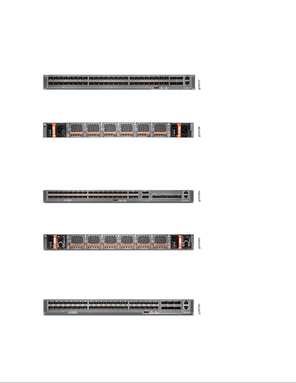
Figure 1 on page 20 and Figure 2 on page 20 show the front and rear, respectively, of a typical ACX5448
router.
Figure 1: ACX5448 Router—Front
Figure 2: AC-Powered ACX5448 Router—Rear
Figure 3 on page 20 and Figure 4 on page 20 show the front and rear, respectively, of a typical ACX5448-D
router.
20
Figure 3: ACX5448-D Router—Front
Figure 4: AC-Powered ACX5448-D Router—Rear
Figure 5 on page 20 and Figure 6 on page 21 show the front and rear, respectively, of a typical ACX5448-M
router.
Figure 5: ACX5448-M Router—Front
Page 20
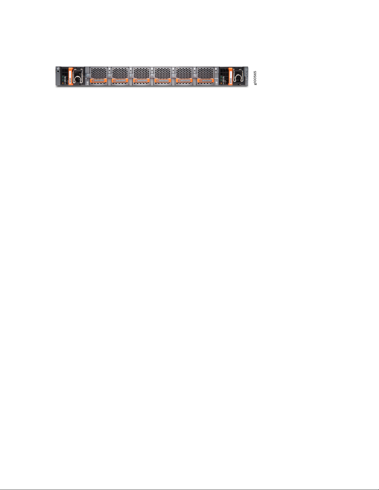
Figure 6: AC-Powered ACX5448-M Router—Rear
Benefits of ACX5400 Routers
Optimized space—The ACX5400 router has a 1 U form factor and is ideal for Ethernet service aggregation.
•
Its innovative design helps service providers build high-density, high-performance 100-Gigabit Ethernet
infrastructures where rack space and cooling are limited.
High performance
•
The 52 ports on the ACX5448 router support 10-Gbps and 100-Gbps speeds providing a total
•
throughput of up to 800 Gbps. The router provides full metro Ethernet and IP/MPLS VPN services in
a space-optimized platform.
21
The ACX5448-D router supports 10-Gigabit, 100-Gigabit, and 100G/200G dense wavelength-division
•
multiplexing (DWDM) ports with a system throughput of up to 800 Gbps. The innovative design of
the ACX5448-D helps service providers develop converged packet optical solutions.
Simplified network architecture— The ACX5400 line of routers simplify access and aggregation
•
architectures by eliminating unnecessary layers and network overlays.
Advanced security capabilities— The ACX5448-M router supports advanced security capabilities such
•
as Media Access Control Security (MACsec) on the 10-Gigabit or 1-Gigabit Ethernet ports to protect
against potential network vulnerabilities.
ACX5448, ACX5448-D, and ACX5448-M System Overview
The ACX5400 routers have a high-throughput Packet Forwarding Engine, and the performance of the
control plane running on ACX5400 routers is enhanced by the 1.9-Ghz six-core Intel CPU with 32-GB of
memory and two 100-GB enterprise-grade solid-state drives (SSDs) for storage.
We ship the ACX5400 routers with redundant fans and redundant power supply modules (PSMs). You
can order the routers with front-to-back airflow (airflow out or AFO) or back-to-front airflow (airflow in
or AFI), and with AC or DC PSMs.
Figure 7 on page 22 shows the important components on the front of the ACX5448 router.
Page 21
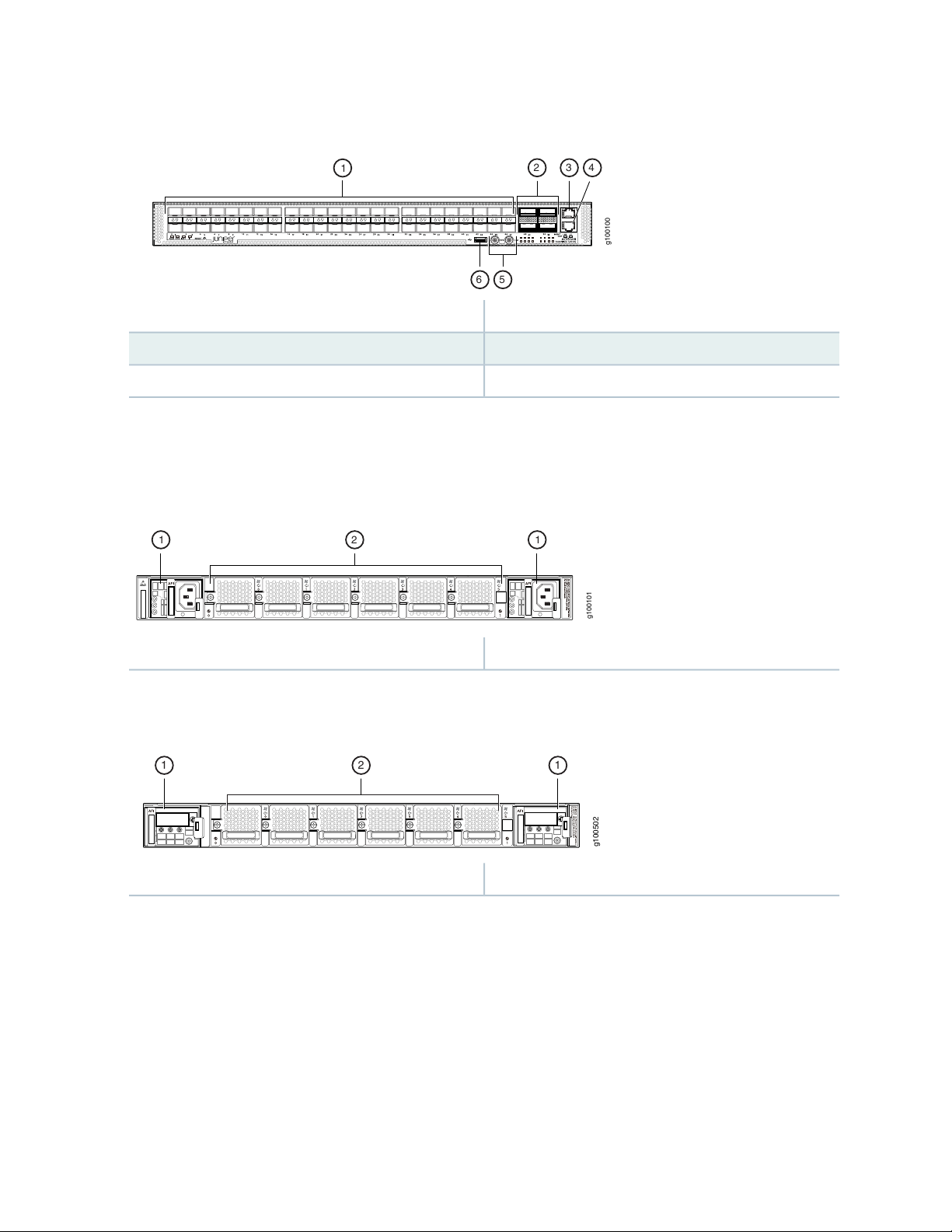
Figure 7: Front View of the ACX5448 Router
g100100
2 3 4
56
1
g100101
21 1
g100502
2 11
4—1— Console (CON) portSFP+ ports
5—2— PPS and 10M GPS output portsQSFP28 ports
6—3— USB portManagement (MGMT) port
Figure 8 on page 22 and Figure 9 on page 22 shows the important components on the rear of the ACX5448
routers.
Figure 8: Rear View of the AC-Powered ACX5448 Router
22
2—1— Fan modulesPower supply modules (AC)
Figure 9: Rear View of the DC-Powered ACX5448 Router
2—1— Fan modulesPower supply modules (DC)
The fan modules and PSMs on the ACX5448 routers are installed in slots on the rear of the chassis. The
chassis has six slots for the fan modules and two slots for the PSMs.
The six fan modules are numbered 0 through 5 from left to right. Similarly, the two PSMs are numbered
0 and 1.
Figure 10 on page 23 shows the important components on the front of the ACX5448-D router.
Page 22

Figure 10: Front View of the ACX5448-D Router
g100500
32 4 5
1
67
g100701
21 1
g100502
2 11
5—1— Console (CON) portSFP+ ports
6—2— PPS and 10M GPS output portsQSFP28 ports
7—3— USB portCFP2 ports
4—Management (MGMT) port
Figure 11 on page 23 and Figure 12 on page 23 show the important components on the rear of the
ACX5448-D routers.
23
Figure 11: Rear View of the AC-Powered ACX5448-D Router
2—1— Fan modulesPower supply modules (AC)
Figure 12: Rear View of the DC-Powered ACX5448-D Router
2—1— Fan modulesPower supply modules (DC)
The fan modules and PSMs on the ACX5448-D routers are installed in slots on the rear of the chassis. The
chassis has six slots for the fan modules and two slots for the PSMs.
The six fan modules are numbered 0 through 5 from left to right. Similarly, the two PSMs are numbered
0 and 1.
Figure 13 on page 24 shows the important components on the front of the ACX5448-M router.
Page 23
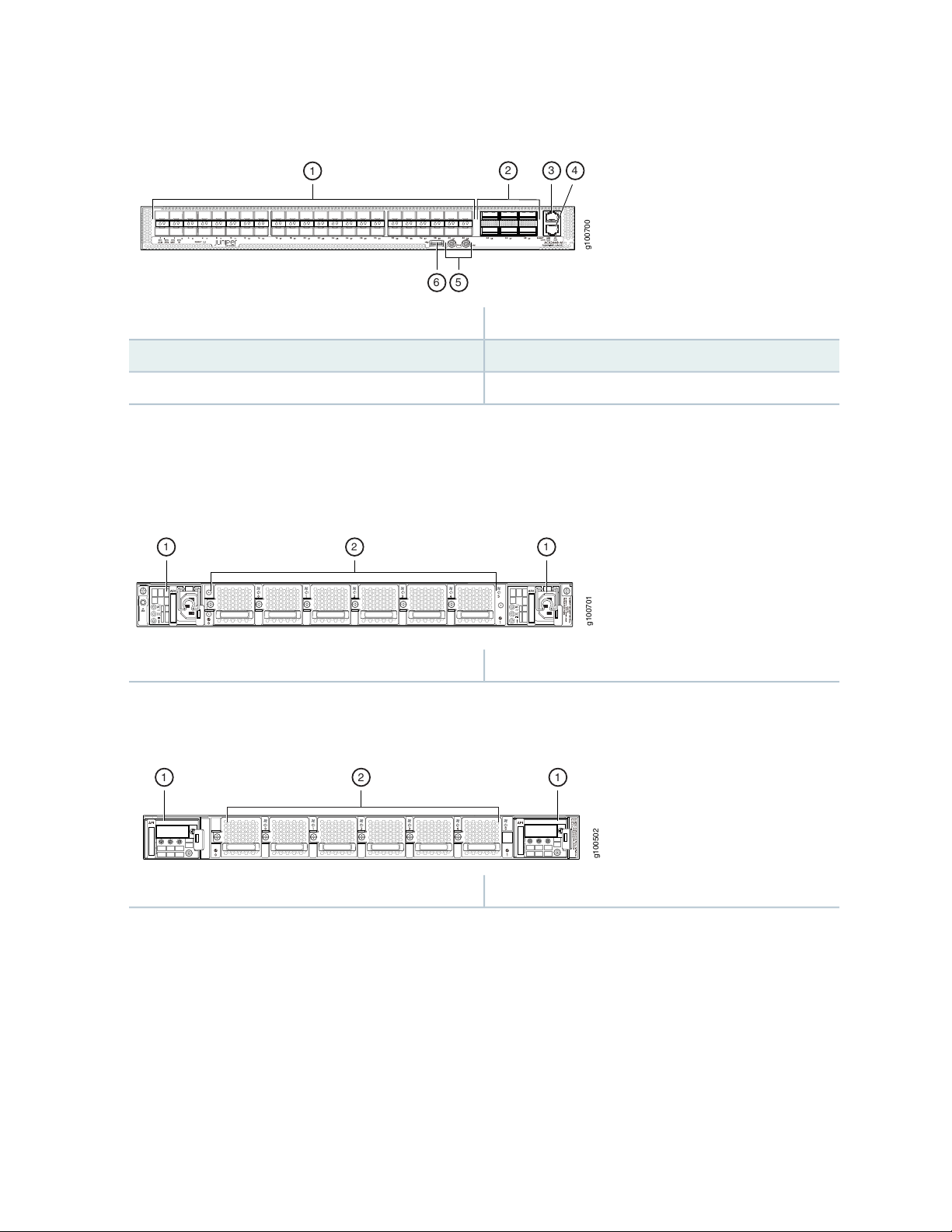
Figure 13: Front View of the ACX5448-M Router
g100700
2 3 4
1
56
g100701
21 1
g100502
2 11
4—1— Console (CON) portSFP+ ports
5—2— PPS and 10M GPS output portsQSFP28 ports
6—3— USB portManagement (MGMT) port
Figure 14 on page 24 and Figure 15 on page 24 show the important components on the rear of the
ACX5448-M routers.
Figure 14: Rear View of the AC-Powered ACX5448-M Router
24
2—1— Fan modulesPower supply modules (AC)
Figure 15: Rear View of the DC-Powered ACX5448-M Router
2—1— Fan modulesPower supply modules (DC)
The fan modules and PSMs on the ACX5448-M routers are installed in slots on the rear of the chassis.
The chassis has six slots for the fan modules and two slots for the PSMs.
The six fan modules are numbered 0 through 5 from left to right. Similarly, the two PSMs are numbered
0 and 1.
Page 24

ACX5400 Router Models
The ACX5400 line of routers are available with either AC or DC power supply modules (PSMs) and with
either airflow-out (AFO) or airflow-in (AFI) cooling. AFO is also known as front-to-back or port-to-FRU
cooling; similarly AFI is known as back-to-front or FRU-to-port cooling.
Table 3 on page 25 lists the model numbers for ACX5448 routers.
Table 3: ACX5448 Router Model Numbers and Description
AirflowPower SupplyModel Number
Airflow in (back-to-front)ACACX5448-AC-AFI
Airflow in (back-to-front)DCACX5448-DC-AFI
Airflow out (front-to-back)ACACX5448-AC-AFO
25
Table 4 on page 25 lists the model numbers for ACX5448-D routers.
Table 4: ACX5448-D Router Model Numbers and Description
Table 5 on page 25 lists the model numbers for ACX5448-M routers.
Table 5: ACX5448-M Router Model Numbers and Description
Airflow out (front-to-back)DCACX5448-DC-AFO
AirflowPower SupplyModel Number
Airflow in (back-to-front)ACACX5448-D-AC-AFI
Airflow in (back-to-front)DCACX5448-D-DC-AFI
Airflow out (front-to-back)ACACX5448-D-AC-AFO
Airflow out (front-to-back)DCACX5448-D-DC-AFO
AirflowPower SupplyModel Number
Airflow in (back-to-front)ACACX5448-M-AC-AFI
Airflow in (back-to-front)DCACX5448-M-DC-AFI
Airflow out (front-to-back)ACACX5448-M-AC-AFO
Page 25

Table 5: ACX5448-M Router Model Numbers and Description (continued)
AirflowPower SupplyModel Number
Airflow out (front-to-back)DCACX5448-M-DC-AFO
CAUTION: Do not mix different types (AC and DC) of power supply modules and
different airflow modules (AFI and AFO) in the same chassis.
Field-Replaceable Units in ACX5400 Routers
Field-replaceable units (FRUs) are components that you can replace at your site. The ACX5400 FRUs are
hot-insertable and hot-removable: you can remove and replace them without powering off the router or
disrupting the routing function.
26
The following are the ACX5400 FRUs:
Power supply modules (PSMs)
•
Fan modules
•
Optical transceivers
•
CAUTION: Replace a failed PSM with a new PSM within one minute of removal to
prevent chassis overheating. The router continues to operate with only one PSM
running. Replace a failed fan module with a new fan module within one minute of
removal to prevent chassis overheating. Do not operate the router with missing FRUs
for longer than one minute.
NOTE: If you have a Juniper J-Care service contract, register any addition, change, or upgrade
of hardware components at
https://www.juniper.net/customers/csc/management/updateinstallbase.jsp. Failure to do so
can result in significant delays if you need replacement parts. This note does not apply if you
replace existing components with the same type of component.
Page 26
NOTE: Before removing the optical transceivers, we recommend that you disable the interface
using the set interfaces interface-name disable command.
Hardware Redundancy of ACX5400 Router Components and Functionality
The following hardware components provide redundancy on ACX5400 routers:
Power supply modules (PSMs)—The ACX5400 routers have two PSMs. Each PSM provides power to all
•
components in the router. If two PSMs are installed, they provide full power redundancy to the device.
If one PSM fails or if you remove one PSM, then the second PSM balances the electrical load without
interruption.
To provide power redundancy to the system, both PSMs must be installed. Connect the first power
source feed to one PSM and the other power source to the second PSM.
27
CAUTION: Do not connect both the power source feeds to the same power supply
input terminal.
Cooling system—The ACX5400 routers have six fan modules. If a fan module fails and is unable to keep
•
the router within the desired temperature thresholds, chassis alarms occur and the router can eventually
shut down. The router can work with one failed fan module for a long duration, but for the router to
work efficiently you must replace the failed fan module immediately.
ACX5400 Routers Hardware and CLI Terminology Mapping
Table 6 on page 28 describes the hardware terms used in ACX5400 router documentation and the
corresponding terms used in the Junos OS command line interface (CLI).
Page 27

Table 6: CLI Equivalents of Terms Used in Documentation for ACX5400 Routers
Hardware
Item (as
Displayed
in the CLI)
Description (as
Displayed in the
CLI)
Value (as
Displayed in the
CLI)
Item in
Documentation
Additional Information
28
Chassis
Engine
FPC n
PIC n
ACX5448-D
ACX5448-M
Abbreviated name of
the Flexible PIC
Concentrator (FPC;
an FPC is equivalent
to a line card)
Abbreviated name of
the Physical
Interface Card (PIC)
Value of n is always
0.
Value of n is a
value in the range
of 0-1.
Router chassis–ACX5448
Built-in Routing Engine.–Routing EngineRouting
The router does not
have actual FPCs. In
this case, FPC refers to
the router itself.
Built-in FPC.
The router does not
have actual PIC
devices; see entries for
PIC n for the equivalent
item on the router.
Built-in network ports
on the front panel of
the router are mapped
to logical PICs.
“Chassis Physical
Specifications for ACX5400
Routers” on page 66
Interface Naming
Conventions Used in the
Junos OS Operational
Commands
Interface Naming
Conventions Used in the
Junos OS Operational
Commands
xcvr n
Abbreviated name of
the transceiver
equivalent to the
number of the port
in which the
transceiver is
installed.
Optical transceiversn is a value
Port and Interface
Specifications
Page 28

Table 6: CLI Equivalents of Terms Used in Documentation for ACX5400 Routers (continued)
Hardware
Item (as
Displayed
in the CLI)
Description (as
Displayed in the
CLI)
Value (as
Displayed in the
CLI)
Item in
Documentation
Additional Information
29
Power supplyPEM n
FanFan tray
n is a value in the
range of 0—1.
range of 0-5.
AC power supply
module
DC power supply
module
Fann is a value in the
“AC Power Supply for
ACX5400 Routers” on
page 53
“DC Power Supply for
ACX5400 Routers” on
page 57
“Cooling System and
Airflow in ACX5448,
ACX5448-D, and
ACX5448-M Routers” on
page 47
ACX5400 System Software Overview
The ACX5400 routers run the Junos operating system (OS), which provides Layer 2 and Layer 3 switching,
routing, and security services. Junos OS is installed on an ACX5400 router’s 100-gigabyte (GB) internal
solid-state flash drive. The same Junos OS code base that runs on an ACX5400 router also runs on all
Juniper Networks QFX and EX Series switches, SRX Series devices, and on MX Series, ACX Series, and
PTX Series routers.
For more information about which features are supported on an ACX5400 router, see Feature Explorer.
You manage the router using the Junos OS command-line interface (CLI), accessible through the console
and out-of-band management ports on the router.
Page 29
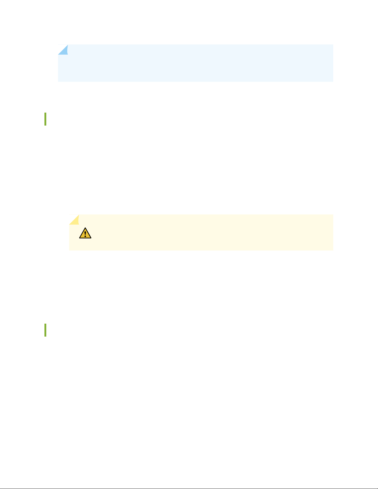
ACX5448, ACX5448-D, and ACX5448-M Chassis
g100235
1
7 6 5 4 3
2
IN THIS SECTION
Management Panel of ACX5400 Routers | 30
Port Panel of ACX5400 Routers | 32
Chassis Status LEDs on ACX5400 Routers | 37
Management Port LEDs on ACX5400 Routers | 40
Network Port LEDs on ACX5400 Routers | 41
Fan Status LEDs on ACX5400 Routers | 43
Power Supply LEDs on ACX5400 Routers | 44
30
The front panel on the ACX5400 chassis contains LEDs for the router components, a reset button,
management and console ports, and network ports. On the front panel, you can view status and
troubleshooting information at a glance.
The rear panel of the router has slots for the power supply modules (PSMs) and fan modules. The power
and fan modules are installed from the rear of the router.
Management Panel of ACX5400 Routers
The management panel of ACX5400 routers is found on the front of the router.
Figure 16 on page 30 shows the management panel components on an ACX5448 router.
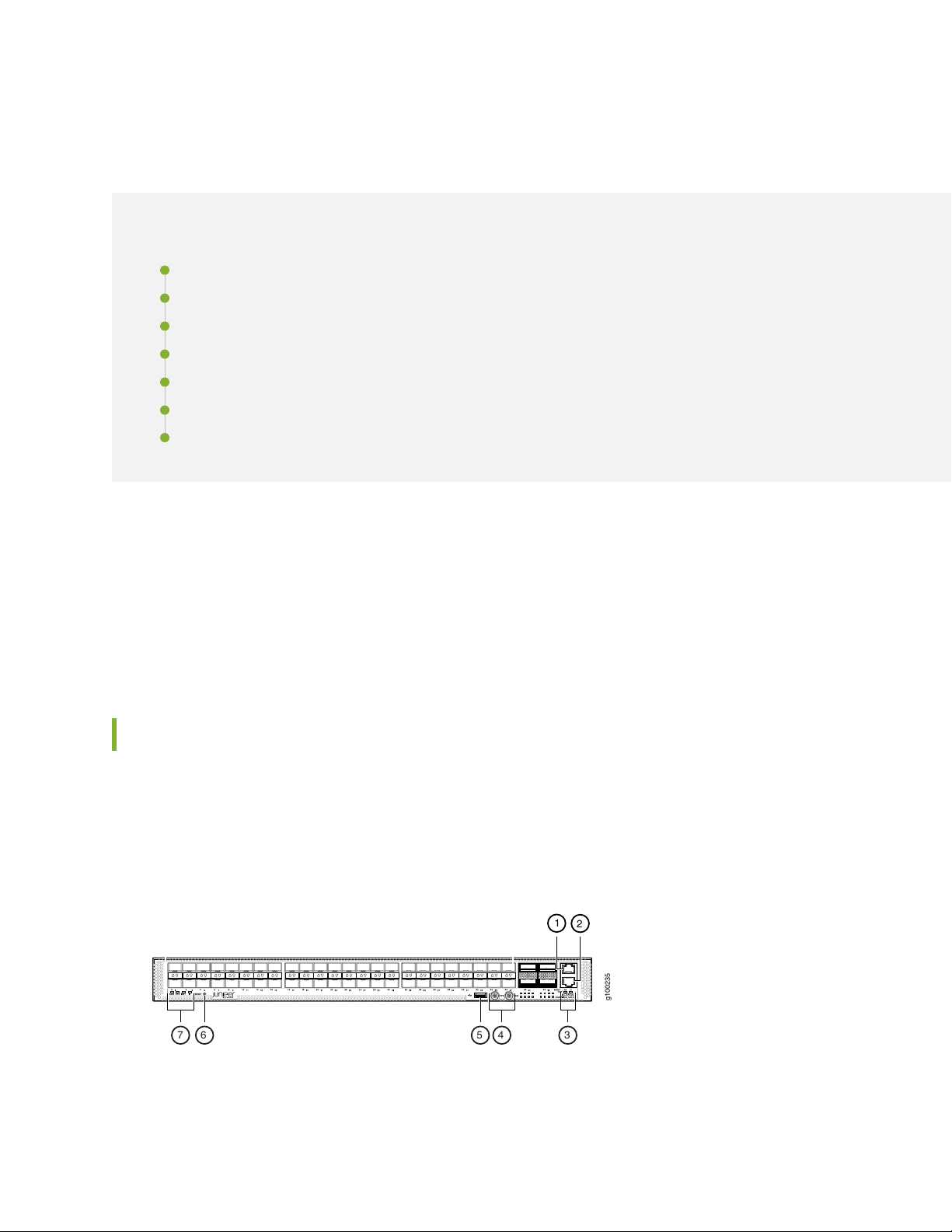
Figure 16: Management Panel Components on ACX5448
Figure 17 on page 31 shows the management panel components on an ACX5448-D router.
Page 30
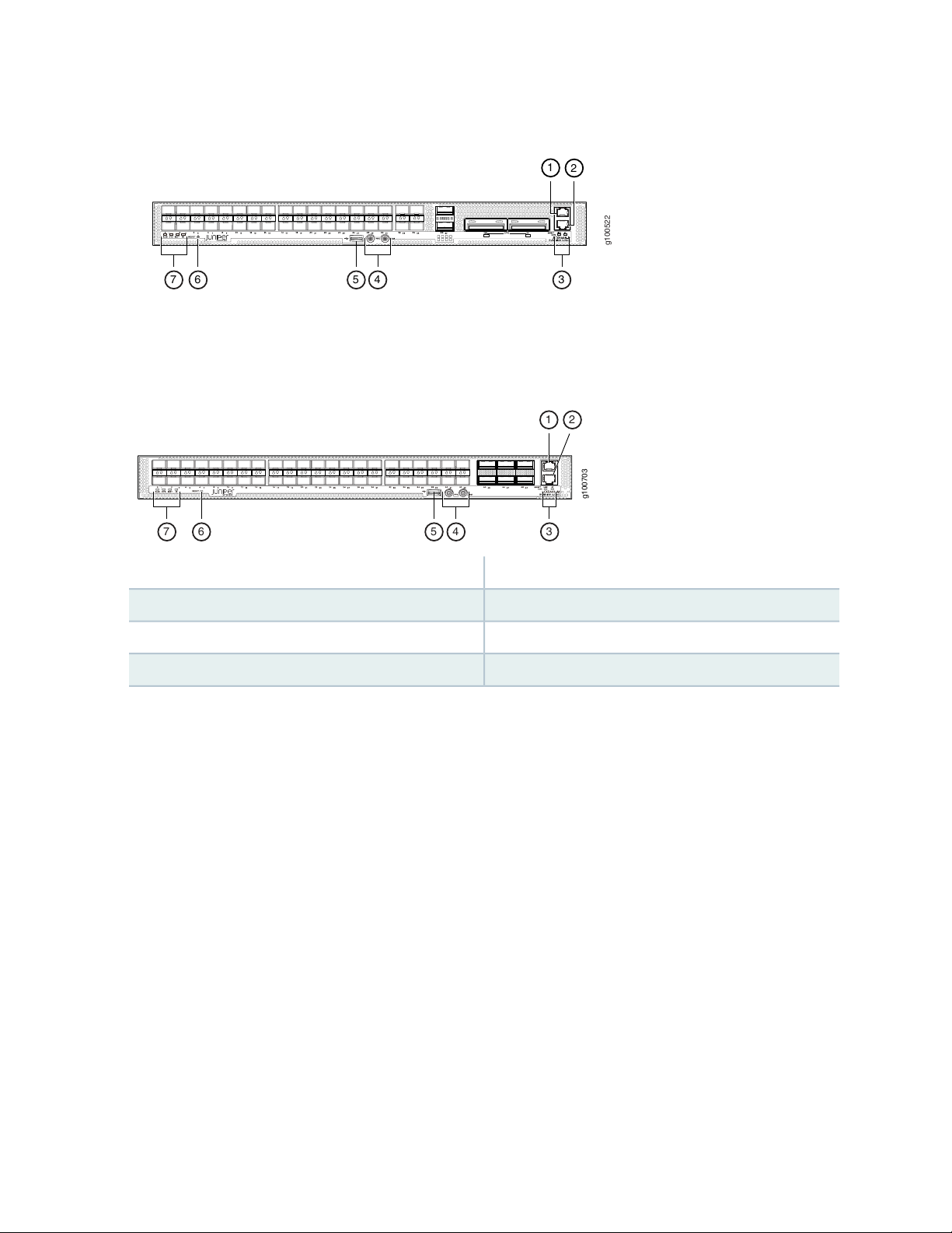
Figure 17: Management Panel Components on ACX5448-D
g100522
1
7 6 5 4 3
2
g100703
1 2
456 37
Figure 18 on page 31 shows the management panel components on ACX5448-M routers.
Figure 18: Management Panel Components on ACX5448-M
31
5—1— USB portManagement (MGMT) port
6—2— RESET buttonConsole (CON) port
7—3— Status LEDsLINK and ST LEDs
4—PPS and 10M GPS output ports
The management panel consists of the following components:
Status LEDs—ALM, SYS, MST, and ID LEDs
•
Router product number
•
Management (MGMT) port— RJ-45 connectors for 10/100/1000BASE-T. See “Connect an ACX5400
•
Router to a Network for Out-of-Band Management” on page 107.
Console (CON) port— RJ-45 connector to support RS-232 serial ports.
•
Link activity (left LED labeled LINK) and port status (right LED labeled ST) LEDs.
•
USB port for image updates.
•
Reset button to reset the device.
•
Two SMB connector ports that support 1-PPS and 10-MHz timing devices.
•
Page 31

Port Panel of ACX5400 Routers
g100234
2
1
IN THIS SECTION
Port Panel of an ACX5448 Router | 32
Port Panel of an ACX5448-D Router | 32
Port Panel of an ACX5448-M Router | 36
Port Panel of an ACX5448 Router
The port panel of the ACX5448 router has the following port configurations:
Forty-eight 10-Gigabit or 1-Gigabit Ethernet ports (ports 0 through 47) that operate at 10-Gbps speed
•
with SFP+ transceivers or at 1-Gbps speed when you use SFP optics.
32
Four 100-Gigabit Ethernet ports (ports 48 through 51) that support quad small form-factor pluggable
•
28 (QSFP28) transceivers. You can channelize these ports into four 25-Gbps interfaces using breakout
cables (and channelization configuration). These ports also support 40-Gbps speed, when you use QSFP+
optics. You can channelize these 40-Gbps ports into four 10-Gbps interfaces using breakout cables (and
channelization configuration).
Figure 19 on page 32 shows the port panel of an ACX5448 router.
Figure 19: ACX5448 Router Port Panel
2—1— 100–Gigabit Ethernet ports (4 QSFP28 ports)10–Gigabit Ethernet ports (48 SFP+ ports)
Port Panel of an ACX5448-D Router
The port panel of the ACX5448-D router has the following port configurations:
Thirty-six 10-Gigabit or 1-Gigabit Ethernet ports (0 through 35, mapped to CLI PIC 0) that operate at
•
10-Gbps speed with SFP+ transceivers or at 1-Gbps speed when you use SFP optics.
Page 32

Two 100-Gigabit Ethernet ports (36 and 37, mapped to CLI PIC 1) that support QSFP28 transceivers.
g100507
32
1
•
You can channelize these ports into four 25-Gbps interfaces using breakout cables (and channelization
configuration). These ports also support 40-Gbps speed, when you use QSFP+ optics. You can channelize
these 40-Gbps ports into four 10-Gbps interfaces using breakout cables (and channelization configuration).
Two 200-Gigabit Ethernet ports (38 and 39, mapped to logical PIC 2) that support 200-gigabit CFP2-DCO
•
transceivers.
NOTE: One QSFP28 port (port 36) and one CFP2-DCO port (port 38) can operate as multiplexer
ports.
Figure 20 on page 33 shows the port panel of an ACX5448-D router.
Figure 20: ACX5448-D Router Port Panel
33
1- Gigabit/10–Gigabit Ethernet ports (36 SFP+ ports)
2—100–Gigabit Ethernet ports (2 QSFP28 ports)
3—1— 100–Gigabit/200-Gigabit Ethernet ports (2
CFP2-DCO ports)
Port, Interface, and PIC Mapping
The ACX5448-D does not have a physical FPC or PIC. FPC 0 refers to the router. The ports on the front
panel are mapped to logical PICs as follows:
Ports 0–35 mapped to PIC 0 (interfaces xe-0/0/0 through xe-/0/0/35)
•
Ports 36 and 37 mapped to PIC 1 (interfaces et-0/1/0 and et-0/1/1)
•
Ports 38 and 39 mapped to PIC 2 (interfaces ot-0/2/0 and ot-0/2/1)
•
For each CFP2-DCO optical module installed in ports 38 and 39, one optical transport (ot-) interface is
created. Therefore, the ACX5448-D supports two ot- interfaces—ot-0/2/0 and ot-0/2/1. You can map
two 100-Gigabit Ethernet (et-) interfaces to each ot- interface, depending on the configured rate—100
Gbps or 200 Gbps—for the CFP2-DCO module. As a result, four et- interfaces are possible—et-0/2/0,
et-0/2/1, et-0/2/2, and et-0/2/3.
Page 33

The optical interface to et mapping is displayed in the following table:
34
Mapped et interface(s)Modulation FormatPort Numberot- interface
et-0/2/0QPSK-100GPort 38ot-0/2/0
8QAM-200G
16QAM-200G
8QAM-200G
16QAM-200G
et-0/2/0
et-0/2/1
et-0/2/0
et-0/2/1
et-0/2/2QPSK-100GPort 39ot-0/2/1
et-0/2/2
et-0/2/3
et-0/2/2
et-0/2/3
Default Port Configuration on ACX5448-D
By default (factory-default configuration), when you power on an ACX5448-D router, the following port
combinations are available:
36 SFP+ ports (ports 0 through 35)—These ports can operate as native 10-Gigabit Ethernet interfaces
•
or as 1-Gigabit Ethernet interfaces when you use 1-gigabit optics.
Two QSFP28 ports (36 and 37)—The interface for port 36 is not created. However, you can configure
•
port 37 as native 100-Gigabit or 40-Gigabit Ethernet interfaces, or channelize these ports into four
25-Gigabit Ethernet or 10-Gigabit Ethernet interfaces, respectively, by using CLI configuration and
breakout cables.
Two CFP2 ports (38 and 39)—You can configure each of the CFP2 ports as a 200-Gigabit Ethernet port.
•
Multiplexing on ACX5448-D Routers
As we have seen in the preceding sections, the et-0/1/0 interface is created for QSFP28 port 36 and the
ot-0/2/0 interface is created for CFP2 port 38. The ot-0/2/0 interface is mapped to the et- interfaces
et-0/2/0 and et-0/2/1.
The QSFP28 port 36 (interface et-0/1/0) and the CFP2 port 38 (interface et-0/2/1) operate as multiplexer
(also called mux) ports.
Page 34

When you start up the router, the et-0/1/0 interface on port 36 is not created by default. However, the
interface et-0/2/0 (on port 38) is always available. You can enable the et-0/1/0 interface (on port 36) by
running the set chassis fpc 0 cfp-to-et command and restarting the FPC by executing the restart
chassis-control command. (This configuration deletes the interface et-0/2/1 on port 38.)
Therefore, you can change the factory-default port combination for the QSFP28 and CFP2 ports to the
following:
QSFP28 ports 36 and 37—Enable the et-0/1/0 interface on port 36. You can configure ports 36 and 37
•
as native 100-Gigabit or 40-Gigabit Ethernet interfaces, or channelize them into four 25-Gigabit Ethernet
or 10-Gigabit Ethernet interfaces, respectively, by using CLI configuration and breakout cables.
CFP2 ports 38 and 39—Configure port 38 as a 100-Gigabit Ethernet port and port 39 as a 200-Gigabit
•
Ethernet port.
Enable Multiplexing by Changing the Default Configuration
In the factory-default configuration, the interface for port 36 is not created. You need to enable it and
then operate it as a multiplexed port 38 (interface et-0/2/1). To change the factory-default port combination
and enable the et-0/1/0 interface (port 36):
35
1. Include the set chassis fpc 0 cfp-to-et command at the [edit] hierarchy level in the configuration mode.
[edit]
user@host# set chassis fpc 0 cfp-to-et
2. Commit the configuration.
[edit]
user@host# commit
3. Restart the FPC.
user@host> restart chassis-control
This configuration deletes the et-0/2/1 interface (on port 38) and creates the et-0/1/0 interface (on port
36). After you change the factory-default port combination, the modified port combination will become
the default port combination when you power on the device.
NOTE: Before changing this default behavior, plan to handle disruption of services.
Page 35

LED Behavior for CFP2 Ports
Table 7 on page 36 summarizes the LED port behavior for CFP2 DCO ports.
Table 7: LED behavior for CFP2 ports
36
DescriptionStateColorMode
OnGreen200G
and the port speed is 200
Gbps but there is no traffic
passing.
FlashingGreen200G
is 200 Gbps, and there is some
activity.
OnAmber100G
and the port speed is 100
Gbps but there is no traffic
passing.
FlashingAmber100G
and the port speed is 100
Gbps and there is some
activity.
First et-
port status
Second et-
port status
First et-
traffic
Second et-
traffic
OffOffUpUpIndicates that the port is up
OnOnUpUpIndicates that the port speed
OffOffDownUpIndicates that the port is up
OffOffUpDown
OffOnDownUpIndicates that the port is up
OnOffUpDown
OffOnUpUp
OnOffUpUp
There is no link on the port.OffUnlit
NOTE: The first et- interface in Table 7 on page 36 refers to the et-0/2/0 interface (port 38) or
the et-0/2/2 interface (port 39). Similarly, the second et interface refers to the et-0/2/1 interface
(port 38) or the et-0/2/3 interface (port 39).
Port Panel of an ACX5448-M Router
The port panel of the ACX5448-M router has the following port configurations:
Forty-four 10-Gigabit or 1-Gigabit Ethernet ports (0 through 43) that operate at 10-Gbps speed with
•
SFP+ transceivers or at 1-Gbps speed when you use SFP optics.
Page 36

Six 100-Gigabit Ethernet ports (44 through 49) that support quad small form-factor pluggable 28 (QSFP28)
g100714
2
1
g100235
1
7 6 5 4 3
2
•
transceivers. You can channelize these ports into four 25-Gbps interfaces using breakout cables (and
channelization configuration). These ports also support 40-Gbps speed, when you use QSFP+ optics.
You can channelize these 40-Gbps ports into four 10-Gbps interfaces using breakout cables (and
channelization configuration).
NOTE: The ACX5448-M routers support advanced security capabilities such as Media Access
Control Security (MACsec). MACsec is supported only on the forty-four 10-Gigabit or
1-Gigabit Ethernet ports.
Figure 21 on page 37 shows the port panel of an ACX5448-M router.
Figure 21: ACX5448-M Router Port Panel
37
2—1— 100–Gigabit Ethernet ports (6 QSFP28 ports)10–Gigabit Ethernet ports (44 SFP+ ports)
Chassis Status LEDs on ACX5400 Routers
The ACX5400 routers have four status LEDs on the front side of the chassis (see callout 7 in
Figure 22 on page 37).
Figure 22: Chassis Status LEDs on an ACX5448 Router
Page 37

Figure 23: Chassis Status LEDs on an ACX5448-D Router
g100522
1
7 6 5 4 3
2
g100703
1 2
456 37
Figure 24: Chassis Status LEDs on an ACX5448-M Router
38
5—1— USB portManagement (MGMT) port
6—2— RESET buttonConsole (CON) port
7—3— Status LEDsLINK and ST LEDs
4—PPS and 10M GPS output ports
Table 8 on page 39 describes the chassis status LEDs on ACX5400 routers, their colors and states, and
the status they indicate. You can view the colors of the three LEDs remotely through the CLI by issuing
the operational mode command show chassis lcd.
Page 38

Table 8: Chassis Status LEDs on ACX5400 Routers
39
DescriptionStateColorName
OffUnlitALM–Alarm or beacon
On steadilyRed
On steadilyAmber
The router is halted or there is no
alarm.
A major hardware fault has occurred,
such as a temperature alarm or power
failure, and the router has halted.
Power off the router by setting the AC
power source outlet to the off (O)
position and unplugging the AC power
cords. Correct any voltage or site
temperature issues, and allow the
router to cool down. Power on the
router and monitor the power supply
and fan LEDs to help determine where
the error is occurring.
A minor alarm has occurred, such as a
software error. Power off the router
by setting the AC power source outlet
to the off (O) position and unplugging
the AC power cords. Power on the
router and monitor the status LEDs to
ensure that Junos OS boots properly.
The router is powered off or halted.OffUnlitSYS–System
On steadilyGreen
OffUnlitID–Identification
BlinkingBlue
Junos OS for ACX Series is loaded on
the router.
The router is a linecard member.OffUnlitMST–Master
The router is a standalone router.On steadilyGreen
The beacon feature is not enabled on
the router. This feature is enabled using
the request chassis beacon command.
The beacon feature is enabled on the
router. This feature is enabled using
the request chassis beacon command.
Page 39

Management Port LEDs on ACX5400 Routers
g100119
1 2
34
g100521
1 2
34
The management ports (labeled MGMT) for 10/100/1000BASE-T connections on ACX5400 routers have
two LEDs that indicate link status and link activity (see callout 3 and 4 in Figure 25 on page 40). The right
LED indicates status; the left LED indicates link activity.
Figure 25: Management Port LEDs on an ACX5448 Router
40
Figure 26: Management Port LEDs on an ACX5448-D Router
Page 40

Figure 27: Management Port LEDs on an ACX5448-M Router
g100704
1 2
34
3—1— Status (ST) LEDManagement (MGMT) port
4—2— Link activity (LINK) LEDConsole (CON) port
41
Table 9 on page 41 describes the management port LEDs.
Table 9: Management Port LEDs on ACX5400 Routers
(Link
Activity;
left)
(Status;
right)
Network Port LEDs on ACX5400 Routers
DescriptionStateColorLED
A link is established, and there is link activity.Blinking or flickeringGreenLINK
A link is established, but there is no link activity.On steadily
No link is established, there is a fault, or the link is down.Off
Indicates that the port speed is 10 Mbps.Blinking at an interval of 200 msGreenST
Indicates that the port speed is 100 Mbps.Blinking at an interval of 83 ms
Indicates that the port speed is 1000 Mbps.On steadily
The ACX5400 routers use bicolored LEDs to indicate link activity on and status of network ports. The link
LED indicates link activity or a fault. The status LED indicates transceiver presence.
Table 10 on page 42 describes how to interpret the SFP+ port LEDs.
Page 41

Table 10: Network Port LEDs on SFP+ Ports for ACX5400 Routers
DescriptionStateColorMode
42
Indicates that the port speed is 10 Gbps, and there
is some activity.
Indicates that the port speed is 1 Gbps, and there
is some activity.
There is no link on the port.UnlitOff
Ethernet or
10-Gigabit
Ethernet
On or flashingGreen1-Gigabit
On or flashingAmber
Table 11 on page 42 describes how to interpret the QSFP28 LEDs.
Table 11: Network Port LEDs on QSFP28 Ports for ACX5400 Routers
DescriptionStateColorMode
On or flashingGreen100-Gigabit
Ethernet
On or flashingAmber40-Gigabit
Ethernet
Indicates that the port speed is 100 Gbps, and there
is some activity.
There is no link on the port.UnlitOff
Indicates that the port speed is 40 Gbps, and there
is some activity.
Ethernet
Ethernet
There is no link on the port.UnlitOff
On or flashingGreen25-Gigabit
On or flashingAmber10-Gigabit
Indicates that the port speed is 25 Gbps (using a
breakout cable), and there is some activity.
There is no link on the port.UnlitOff
Indicates that the port speed is 10 Gbps (using a
breakout cable), and there is some activity.
There is no link on the port.UnlitOff
Page 42

NOTE: There are four bicolor lane LEDs for each QSFP28 port that are located just below the
g100519
1
QSFP28 ports. The first LED is used and the remaining LEDs are not used when the port is
configured as a 40-Gigabit Ethernet or 100-Gigabit Ethernet interface, and connected to a
QSFP28 transceiver. All four LEDs are used when the port is configured as a 10-Gigabit Ethernet
or 25-Gigabit Ethernet interface, and the port is connected using an optical split cable (breakout
cable) or a direct attach copper breakout (DACBO) cable.
Table 12 on page 43 describes how to interpret CFP2 port LEDs.
Table 12: CFP2 Port LEDs on ACX5448-D Routers
DescriptionStateColorMode
43
Indicates that the port speed is 200 Gbps, and
there is some activity.
Indicates that the port speed is 100 Gbps, and
there is some activity.
There is no link on the port.UnlitOff
Ethernet or
200-Gigabit
Ethernet
On or flashingGreen100-Gigabit
On or flashingAmber
Fan Status LEDs on ACX5400 Routers
The fan modules on ACX5400 routers do not have any LEDs—the fan status LEDs are located next to the
fan module slots on the ACX5400 chassis. Figure 28 on page 43 shows the location of the LED next to
the fan module.
Figure 28: Fan Status LEDs on ACX5400 Routers
1—Fan LEDs
Table 13 on page 44 describes the function of the fan status LED.
Page 43

Table 13: Fan Status LED on ACX5400 Routers
44
DescriptionStateColorName
On steadilyGreenFan
On steadilyRed
Power Supply LEDs on ACX5400 Routers
IN THIS SECTION
The fan module is operating normally. The
system has verified that the module is
engaged, that the airflow is in the correct
direction, and that the fan is operating
correctly.
An error has been detected in the fan
module. Replace the fan module as soon
as possible. Either the fan has failed or it
is seated incorrectly. To maintain proper
airflow through the chassis, leave the fan
module installed in the chassis until you
are ready to replace it.
AC Power Supply LEDs on ACX5400 Routers | 44
DC Power Supply LEDs on ACX5400 Routers | 46
AC Power Supply LEDs on ACX5400 Routers
Figure 29 on page 45 shows the location of the LEDs on the ACX5448 power supply module (PSM).
Page 44

Figure 29: AC Power Supply LEDs on an ACX5448 Router
g100508
1
2
3
g100718
1
2
3
4
5
3—1— Fault LEDInput status LED
2—Output status LED
Figure 30 on page 45 shows the location of the LEDs on the ACX5448-D and ACX5448-M PSM (see
callouts 1, 2, and 3).
Figure 30: AC Power Supply LEDs on an ACX5448-D and ACX5448-M Router
45
3—1— Fault LEDInput status LED
2—Output status LED
Table 14 on page 45 describes the LEDs on the AC PSMs.
Table 14: AC Power Supply Module LEDs on ACX5400 Routers
DescriptionStateColorLED
There is no input power to the PSM.OffUnlitAC
There is input AC power to the PSMOn steadilyGreen
There is no output voltage from the PSM. Check the PSM.OffUnlitDC
There is output voltage from the PSM.On steadilyGreen
Page 45

Table 14: AC Power Supply Module LEDs on ACX5400 Routers (continued)
g100112
1
2 3
DescriptionStateColorLED
46
On steadilyAmber! (fault)
An error is detected in the PSM. Replace the PSM as soon as
possible. To maintain proper airflow through the chassis, leave
the PSM installed in the chassis until you are ready to replace
it.
NOTE: If the AC OK LED and the DC OK LED are unlit, either the AC power cord is not installed
properly or the power supply fuse has failed. If the AC OK LED is lit and the DC OK LED is unlit,
the AC PSM is installed properly, but the power supply has an internal failure.
DC Power Supply LEDs on ACX5400 Routers
Figure 31 on page 46 shows the location of the LEDs on the DC PSM.
Figure 31: DC Power Supply Faceplate on ACX5400 Routers
3—1— Fault LEDInput LED
2—Output LED
CAUTION: The V+ terminals are shunted internally, as are the V– terminals. The same
polarity terminal can be wired together from the same source to provide an additional
current path in a higher-power chassis. Do not connect the terminals to different
sources.
Table 15 on page 47 describes the LEDs on the DC PSMs.
Page 46

Table 15: DC Power Supply LEDs on ACX5400 Routers
47
DescriptionStateColorName
There is no input power to the PSM.OffUnlitIN
There is input DC power to the PSM.On steadilyGreen
OffUnlitOUT
On steadilyAmber! (fault)
There is no output voltage from the PSM.
Check the PSM.
There is output voltage from the PSM.On steadilyGreen
An error is detected in the PSM. Replace the
PSM as soon as possible. To maintain proper
airflow through the chassis, leave the PSM
installed in the chassis until you are ready to
replace it.
Cooling System and Airflow in ACX5448, ACX5448-D, and ACX5448-M Routers
IN THIS SECTION
Fan Modules | 48
Fan Module and Power Supply Requirement | 50
Fan Module Status | 51
The cooling system in ACX5400 routers consists of six fan modules and a single fan in each power supply
module (PSM). The ACX5400 routers can be set up to work in the following airflow directions:
Airflow in (AFI)—Air comes into the router through the vents in the field-replaceable units (FRUs)
•
Airflow out (AFO)—Air comes into the router through the vents in the front panel.
•
Page 47

CAUTION: Do not mix fan modules and PSMs with AFO and AFI labels in the same
g100520
chassis.
Fan Modules
The fan modules in ACX5400 routers are hot-insertable and hot-removable field-replaceable units (FRUs).
The fan modules are installed in the fan module slots on the rear of the router. The ACX5400 routers
support six fan modules numbered 0 through 5 from left to right, with each fan module slot having a fan
icon next to it.
The ACX5400 routers are available with either front-to-back airflow (airflow out, ports-to-FRUs, or AFO),
or back-to-front airflow (airflow in, FRUs-to-ports, or AFI). In AFO models, the air is pulled through the
front of the chassis toward the fan modules, from where it is exhausted out of the chassis. In AFI models,
the air is pulled through the fan modules and toward the front of the chassis, from where it is exhausted
out of the chassis. The fan modules and the power modules are available in both AFO and AFI models.
48
Figure 32 on page 48 shows an ACX5400 fan module.
Figure 32: Fan Module Used in ACX5400 Routers
You remove and replace a fan module from the FRU end of the chassis. The router continues to operate
for a limited period of time (30 seconds) during the replacement of the fan module without thermal
shutdown.
NOTE: All fan modules must be installed for optimal operation of the router.
Table 16 on page 49 lists the available fan modules and the direction of airflow in them.
Page 48

Table 16: Fan Module in ACX5400 Routers
Label on
the Fan
Module
HandleAirflow DiagramFan Module
Color of
Fan
Module
Direction of
Airflow in the
Fan Module
49
Power
Supplies
ACX5448-D-FAN-AFI
ACX5448-D-FAN-AFO
AIR INFigure 33 on page 50ACX5448-FAN-AFI
AIR OUTFigure 34 on page 50ACX5448-FAN-AFO
Juniper
Azure
Blue
Juniper
Gold
Air is pulled
through the fan
modules and
toward the front of
the chassis, from
where it is
exhausted out of
the chassis.
Air is pulled
through the front
of the chassis
toward the fan
modules, from
where it is
exhausted out of
the chassis.
You must
install PSMs
that have
AIR IN labels
only in those
routers in
which the
fan modules
have AIR IN
labels.
You must
install PSMs
that have
AIR OUT
labels only in
those routers
in which the
fan modules
have AIR
OUT labels.
In data center deployments, position the router in such a manner that the AIR IN labels on router
components are next to the cold aisle, and AIR OUT labels on router components are next to the hot aisle.
Page 49

Figure 33: Air In Airflow Through ACX5400 Chassis—AFI
g100524
FRUsPorts
g100525
FRUsPorts
Figure 34: Air Out Airflow Through ACX5400 Chassis—AFO
50
Fan Module and Power Supply Requirement
Do not mix PSMs with different airflow. If the PSMs are color-coded, ensure they are either all azure blue
for the airflow-in (AFI) models or all gold for airflow-out (AFO) models. If the PSMs are not color-coded
but have a label, ensure that the chassis is either using all airflow in (AFI) or using all airflow out (AFO).
Likewise, ensure that all fan modules have the same airflow and match the airflow of the PSMs. Fan modules
are also color-coded either azure blue for airflow in or gold for airflow out. If the fan module has a label
instead of being color-coded, ensure that labels (AIR IN and AIR OUT) are not mixed. If the fan modules
Page 50

have AIR IN labels, the color of the PSM handle must be azure blue; if the fan modules have AIR OUT
labels, the color of the PSM handle must be gold.
Mixing components with different airflows in the same chassis hampers the performance of the cooling
system of the router and leads to overheating of the chassis.
CAUTION: The system raises an alarm if a fan module fails or if the ambient
temperature inside the chassis rises above the acceptable range. If the temperature
inside the chassis rises above the threshold temperature, the system shuts down
automatically.
Do not mix fan modules with different wattage. Only use the replacement fan modules that are designed
for use with your product number. See Table 16 on page 49 for the correct part number for your ACX5400
router.
However, if you need to convert an ACX5400 device to have a different airflow, you can change the airflow
pattern. To convert an AIR IN product model to an AIR OUT product model or an AIR OUT product model
to a AIR IN product model, you must replace all of the fan modules and PSMs at one time to use the new
direction.
51
NOTE: You must power off the device before replacing all the fans and power supplies and then
power on the device. If you replace the fans or power supplies without powering off the device,
the system will raise an alarm.
Fan Module Status
You can check the status of fan modules through the show system alarms command or by looking at the
LEDs next to each fan module. The fan module does not have any status LED—the fan module status LED
is located on the chassis.
Each router has a status LED for each fan module on the right side of the corresponding fan module slot.
It indicates the status of the corresponding fan module. Table 17 on page 52 describes the fan module
status LED in an ACX5400 router.
Page 51

Table 17: Fan Module Status
52
DescriptionStateLED Color
On steadilyGreen
On steadilyRed
Under normal operating conditions, the fan modules operate at a moderate speed. Temperature sensors
in the chassis monitor the temperature within the chassis.
The system raises an alarm if a fan module fails or if the ambient temperature inside the chassis rises above
the acceptable range. If the temperature inside the chassis rises above the threshold temperature, the
system shuts down automatically.
The fan module is operating normally. The system has verified
that the module is engaged, that the airflow is in the correct
direction, and that the fan is operating correctly.
An error has been detected in the fan module. Replace the fan
module as soon as possible. Either the fan has failed or it is
seated incorrectly. To maintain proper airflow through the
chassis, leave the fan module installed in the chassis until you
are ready to replace it.
ACX5448, ACX5448-D, and ACX5448-M Power System
IN THIS SECTION
AC Power Supply for ACX5400 Routers | 53
AC Power Specifications for ACX5400 Routers | 55
AC Power Cord Specifications for ACX5400 Routers | 55
DC Power Supply for ACX5400 Routers | 57
DC Power Specifications for ACX5400 Routers | 59
Page 52

AC Power Supply for ACX5400 Routers
g100107
The ACX5448 AC router operates at 650 W while the ACX5448-D and ACX5448-M AC routers need
850 W. The two power supply modules (PSMs) in ACX5400 routers are hot-removable and hot-insertable
field-replaceable units (FRUs). The PSMs are installed in the router at the factory. You can replace the
PSMs without powering off the router or disrupting the router function.
NOTE: Both the AFI and AFO PSMs look identical. Be sure to use the correct PSM for your
chassis product model (see Table 18 on page 54 for ACX5448 routers and Table 19 on page 55
for ACX5448-D and ACX5448-M routers).
CAUTION: Do not mix PSMs with different airflow in the same chassis. The system
raises an alarm when a PSM having a different airflow is inserted into the chassis.
53
CAUTION: Do not mix AC and DC PSMs in the same chassis.
Figure 35 on page 53 shows the AC PSM in ACX5448 routers.
Figure 35: AC PSM in an ACX5448 Router
Figure 36 on page 54 shows the AC PSM in ACX5448-D and ACX5448-M routers.
Page 53

Figure 36: AC PSM in ACX5448-D and ACX5448-M Routers
g100509
The PSMs provide FRU-to-port or port-to-FRU airflow depending on the product model you purchase.
The PSMs either have labels on the handles that indicate the direction of airflow or have color-coded
handles with a fan icon. A PSM with the label AFI or a blue handle denotes FRU-to-port airflow. A PSM
with the label AFO or a gold-colored handle denotes port-to-FRU airflow.
CAUTION: Verify that the airflow direction on the PSM handle matches the direction
of airflow in the chassis. Ensure that each PSM that you install in the chassis has the
same airflow direction. If you install PSM with two different airflow directions, Junos
OS raises an alarm. If you need to convert the airflow pattern on a chassis, you must
replace all the fans and PSMs at one time to use the new direction.
54
Table 18 on page 54 and Table 19 on page 55 show the different PSMs and their direction of airflow.
Table 18: Airflow Direction in AC PSM for ACX5448
Color of Power
Supply Module
HandleDirection of AirflowWattagePower Supply Modules
Juniper Azure BlueAirflow in (back-to-front)650 WJPSU-650W-AC-AFI
JPSU-650W-AC-AFO
(front-to-back)
Juniper GoldAirflow out
Page 54

Table 19: Airflow Direction in AC PSM for ACX5448-D and ACX5448-M
55
Color of Power
Supply Module
HandleDirection of AirflowWattagePower Supply Modules
Juniper Azure BlueAirflow in (back-to-front)850 WJPSU-850W-AC-AFI
JPSU-850W-AC-AFO
(front-to-back)
AC Power Specifications for ACX5400 Routers
Table 20 on page 55 describes the AC power specifications for ACX5400 routers.
Table 20: AC Power Specifications for ACX5400 Routers
Specifications for
ACX5448-D
Operating range:
100–240 VAC
•
50–60 Hz (all product
models)
AC input voltage
AC input line frequency
Specifications for
ACX5448Item
Operating range:
100–240 VAC
•
50–60 Hz (all product
models)
Juniper GoldAirflow out
Specifications for
ACX5448-M
Operating range:
100–240 VAC
•
50–60 Hz (all product
models)
AC input current rating
consumption
consumption
7.8 A at 100–120 VAC
•
3.8 A at 200–240 VAC
•
5.6 A at 100–120 VAC
•
2.3 A at 200–240 VAC
•
6.5 A at 100–120 VAC
•
2.7 A at 200–240 VAC
•
300 W340 W250 WTypical power
550 W550 W450 WMaximum power
AC Power Cord Specifications for ACX5400 Routers
We ship detachable AC power cords with the chassis if you include them as part of your order. The coupler
is type C13 as described by International Electrotechnical Commission (IEC) standard 60320. The plug at
Page 55

the male end of the power cord fits into the power source outlet that is standard for your geographical
location.
NOTE: In North America, AC power cords must not exceed 14.75 feet (approximately 4.5 meters)
in length, to comply with National Electrical Code (NEC) Sections 400-8 (NFPA 75, 5-2.2) and
210-52 and Canadian Electrical Code (CEC) Section 4-010(3). The ACX series power cords comply
with the standards.
Table 21 on page 56 lists AC power cord specifications provided for each country or region.
Table 21: AC Power Cord Specifications
Juniper Model NumberPlug StandardsElectrical SpecificationsCountry/Region
CBL-EX-PWR-C13-ARIRAM 2073 Type RA/3250 VAC, 10 A, 50 HzArgentina
56
Switzerland, and United
Kingdom)
Japan
Korea
250 VAC, 10 A, 50 HzAustralia
Hz
Hz
CBL-EX-PWR-C13-AUAS/NZZS 3112 Type
SAA/3
CBL-EX-PWR-C13-BRNBR 14136 Type BR/3250 VAC, 10 A, 50 HzBrazil
CBL-EX-PWR-C13-CHGB 1002-1996 Type PRC/3250 VAC, 10 A, 50 HzChina
CBL-EX-PWR-C13-EUCEE (7) VII Type VIIG250 VAC, 10 A, 50 HzEurope (except Italy,
CBL-EX-PWR-C13-INIS 1293 Type IND/3250 VAC, 10 A, 50 HzIndia
CBL-EX-PWR-C13-ILSI 32/1971 Type IL/3G250 VAC, 10 A, 50 HzIsrael
CBL-EX-PWR-C13-ITCEI 23-16 Type I/3G250 VAC, 10 A, 50 HzItaly
CBL-EX-PWR-C13-JPSS-00259 Type VCTF125VAC, 12 A, 50 Hz or 60
CBL-EX-PWR-C13-KRCEE (7) VII Type VIIGK250 VAC, 10 A, 50 Hz or 60
CBL-EX-PWR-C13-USNEMA 5-15 Type N5-15125 VAC, 13 A, 60 HzNorth America
250 VAC, 10 A, 50 HzSouth Africa
ZA/13
CBL-EX-PWR-C13-SASABS 164/1:1992 Type
Page 56

Table 21: AC Power Cord Specifications (continued)
57
Juniper Model NumberPlug StandardsElectrical SpecificationsCountry/Region
CBL-EX-PWR-C13-SZSEV 6534-2 Type 12G250 VAC, 10 A, 50 HzSwitzerland
Taiwan
50 Hz
CBL-EX-PWR-C13-TWNEMA5-15P Type N5-15P125 VAC, 11 A and 15 A,
CBL-EX-PWR-C13-UKBS 1363/A Type BS89/13250 VAC, 10 A, 50 HzUnited Kingdom
Figure 37 on page 57 illustrates the plug on the power cord for some of the countries or regions listed in
Table 21 on page 56.
Figure 37: AC Plug Types
DC Power Supply for ACX5400 Routers
The two power supply modules (PSMs) in ACX5400 routers are hot-removable and hot-insertable
field-replaceable units (FRUs). The PSMs are installed in the router at the factory. The DC power supply
in ACX5448 is 650 W and ACX5448-D and ACX5448-M is 850 W with dual feeds for power resiliency.
You can install replacement PSMs without powering off the router or disrupting the router function.
NOTE: Both the AFI and AFO PSMs look identical. Be sure to use the correct PSM for your
chassis product model (see Table 22 on page 58).
CAUTION: Do not mix PSMs with different airflow. The system raises an alarm when
a PSM with a different airflow is inserted into the chassis.
Figure 38 on page 58 shows the DC PSM in ACX5448 routers.
Page 57

Figure 38: DC PSM in an ACX5448 router
g100113
g100515
Figure 39 on page 58 shows the DC PSM in ACX5448-D and ACX5448-M routers.
Figure 39: DC PSM in ACX5448-D and ACX5448-M Routers
58
NOTE: The DC PSM in the router has four terminals labeled V–, V–, V+, and V+ for connecting
DC power source cables labeled positive (+) and negative (–). The V+ terminals are shunted
together, as are the V– terminals.
Table 22 on page 58 and Table 23 on page 59 show the different PSMs and their direction of airflow.
Table 22: Airflow Direction in DC PSM for ACX5448
Color of Power
Supply Module
HandleDirection of AirflowWattagePower Supply Module Number
Juniper Azure BlueAirflow in (back-to-front)650 WJPSU-650W-DC-AFI
JPSU-650W-DC-AFO
(front-to-back)
Juniper GoldAirflow out
Page 58

Table 23: Airflow Direction in DC PSM for ACX5448-D and ACX5448-M routers
59
Color of Power
Supply Module
HandleDirection of AirflowWattagePower Supply Module Number
Juniper Azure BlueAirflow in (back-to-front)850 WJPSU-850W-DC-AFI
JPSU-850W-DC-AFO
(front-to-back)
DC Power Specifications for ACX5400 Routers
Table 24 on page 59 describes the DC power specifications for routers.
Table 24: DC Power Specifications for ACX5400 Routers
Specifications for
ACX5448-D
Rated operating voltage:
•
–48 VDC through –60
VDC
Operating voltage range:
•
–43.2 VDC through –72
VDC
DC input voltage
Specifications for
ACX5448Item
Rated operating voltage:
•
–48 VDC through –60
VDC
Operating voltage range:
•
–40.8 VDC through –72
VDC
Juniper GoldAirflow out
Specifications for
ACX5448-M
Rated operating voltage:
•
–48 VDC through –60 VDC
Operating voltage range:
•
–43.2 VDC through –72
VDC
rating
consumption
consumption
13.5 A maximum11.4 A maximum20 A maximumDC input current
300 W340 W250 WTypical power
550 W525 W450 WMaximum power
Page 59

2
CHAPTER
Site Planning, Preparation, and
Specifications
Site Preparation Checklist for ACX5448, ACX5448-D, and ACX5448-M Routers | 63
ACX5448, ACX5448-D, and ACX5448-M Site Guidelines and Requirements | 64
ACX5448, ACX5448-D, and ACX5448-M Network Cable and Transceiver
Planning | 73
ACX5448, ACX5448-D, and ACX5448-M Management and Console Port
Specifications and Pinouts | 80
Page 60

Page 61

Site Preparation Checklist for ACX5448, ACX5448-D, and ACX5448-M Routers
The checklist in Table 25 on page 63 summarizes the tasks you need to perform when preparing a site for
an ACX5400 router installation.
Table 25: Site Preparation Checklist
DatePerformed byFor More InformationItem or Task
Environment
63
Verify that environmental factors such as
temperature and humidity do not exceed
router tolerances.
Power
Measure the distance between external
power sources and router installation site.
Calculate the power consumption and
requirements.
Rack or Cabinet
Verify that your rack or cabinet meets the
minimum requirements for the installation
of the router.
“ACX5400 Router Environmental
Requirements and Specifications”
on page 67
“AC Power Specifications for
ACX5400 Routers” on page 55
“DC Power Specifications for
ACX5400 Routers” on page 59
“Rack Requirements for ACX5400
Routers” on page 72
“Cabinet Requirements for
ACX5400 Routers” on page 71
Plan rack or cabinet location, including
required space clearances.
Secure the rack or cabinet to the floor and
building structure.
Cables
“Clearance Requirements for
Airflow and Hardware Maintenance
for ACX5400 Routers” on page 70
Page 62

Table 25: Site Preparation Checklist (continued)
64
DatePerformed byFor More InformationItem or Task
Acquire cables and connectors:
Determine the number of cables needed
•
based on your planned configuration.
Review the maximum distance allowed
•
for each cable. Choose the length of
cable based on the distance between the
hardware components being connected.
Plan the cable routing and management.
“Determining Transceiver Support
for ACX5400” on page 74
Cable Specifications for QSFP+ and
QSFP28 Transceivers
ACX5448, ACX5448-D, and ACX5448-M Site Guidelines and Requirements
IN THIS SECTION
General Site Guidelines | 65
Site Electrical Wiring Guidelines | 65
Chassis Physical Specifications for ACX5400 Routers | 66
ACX5400 Router Environmental Requirements and Specifications | 67
ACX5400 Grounding Cable and Lug Specifications | 68
Clearance Requirements for Airflow and Hardware Maintenance for ACX5400 Routers | 70
Cabinet Requirements for ACX5400 Routers | 71
Rack Requirements for ACX5400 Routers | 72
Page 63

General Site Guidelines
Efficient device operation requires proper site planning and maintenance and proper layout of the equipment,
rack or cabinet (if used), and wiring closet.
To plan and create an acceptable operating environment for your device and prevent environmentally
caused equipment failures:
Keep the area around the chassis free from dust and conductive material, such as metal flakes.
•
Follow prescribed airflow guidelines to ensure that the cooling system functions properly and that
•
exhaust from other equipment does not blow into the intake vents of the device.
Follow the prescribed electrostatic discharge (ESD) prevention procedures to prevent damaging the
•
equipment. Static discharge can cause components to fail completely or intermittently over time.
Install the device in a secure area, so that only authorized personnel can access the device.
•
65
Site Electrical Wiring Guidelines
Table 26 on page 65 describes the factors you must consider while planning the electrical wiring at your
site.
WARNING: You must provide a properly grounded and shielded environment and use
electrical surge-suppression devices.
Table 26: Site Electrical Wiring Guidelines
GuidelinesSite Wiring Factor
Signaling limitations
If your site experiences any of the following problems, consult experts in electrical surge
suppression and shielding:
Improperly installed wires cause radio frequency interference (RFI).
•
Damage from lightning strikes occurs when wires exceed recommended distances or
•
pass between buildings.
Electromagnetic pulses (EMPs) caused by lightning damage unshielded conductors and
•
electronic devices.
Page 64

Table 26: Site Electrical Wiring Guidelines (continued)
GuidelinesSite Wiring Factor
66
Radio frequency
interference
Electromagnetic
compatibility
To reduce or eliminate RFI from your site wiring, do the following:
Use a twisted-pair cable with a good distribution of grounding conductors.
•
If you must exceed the recommended distances, use a high-quality twisted-pair cable
•
with one ground conductor for each data signal when applicable.
If your site is susceptible to problems with electromagnetic compatibility (EMC), particularly
from lightning or radio transmitters, seek expert advice.
Some of the problems caused by strong sources of electromagnetic interference (EMI)
are:
Destruction of the signal drivers and receivers in the device
•
Electrical hazards as a result of power surges conducted over the lines into the equipment
•
Chassis Physical Specifications for ACX5400 Routers
The ACX5400 router chassis is a rigid sheet-metal structure that houses the hardware components.
Table 27 on page 66, Table 28 on page 67, and Table 29 on page 67 summarize the physical specifications
of ACX5448, ACX5448-D, and ACX5448-M routers and their components.
Table 27: Physical Specifications for an ACX5448 Router Chassis and FRUs
1.70 in. (4.33 cm)ACX5448
17.26 in.
(43.84 cm)
Without fan module and power
supply module (PSM) handles:
20.29 in. (51.53 cm)
With fan module and PSM
handles: 21.81 in.(55.41 cm)
WeightDepthWidthHeightItem
With FRUs installed:
•
22.48 lb (10.2 kg)
With no FRUs
•
installed: 16 lb
(7.26 kg)
0.35 lb (0.16 kg)3.62 in. (9.19 cm)1.59 in. (4.05 cm)1.62 in. (4.11 cm)Fan module
2.2 lb (1 kg)14.50 in. (36.83 cm)2.23 in. (5.66 cm)1.58 in. (4.01 cm)AC PSM
2.2 lb (1 kg)14.53 in. (36.91 cm)2.23 in. (5.66 cm)1.67 in. (4.24 cm)DC PSM
Page 65

Table 28: Physical Specifications for an ACX5448-D Router Chassis and FRUs
67
WeightDepthWidthHeightItem
1.70 in. (4.33 cm)ACX5448-D
17.26 in.
(43.84 cm)
Without fan module and PSM
handles: 20.29 in. (51.53 cm)
With fan module and PSM
handles: 21.81 in.(55.41 cm)
Table 29: Physical Specifications for an ACX5448-M Router Chassis and FRUs
1.70 in. (4.33 cm)ACX5448-M
17.26 in.
(43.84 cm)
Without fan module and power
supply module handles: 24.0 in.
(61.0 cm)
With fan module and power
supply module handles:
25.5 in.(64.8 cm)
With FRUs installed:
•
23.14 lb (10.5 kg)
With no FRUs
•
installed: 16.76 lb
(7.6 kg)
0.33 lb (0.15 kg)3.62 in. (9.19 cm)1.59 in. (4.05 cm)1.62 in. (4.11 cm)Fan module
2.2 lb (1 kg)14.50 in. (36.83 cm)2.23 in. (5.66 cm)1.58 in. (4.01 cm)AC PSM
2.2 lb (1 kg)14.53 in. (36.91 cm)2.23 in. (5.66 cm)1.67 in. (4.24 cm)DC PSM
WeightDepthWidthHeightItem
With FRUs installed:
•
26.12 lb (11.85 kg)
With no FRUs
•
installed: 19.73 lb
(8.95 kg)
0.33 lb (0.15 kg)3.62 in. (9.19 cm)1.59 in. (4.05 cm)1.62 in. (4.11 cm)Fan module
2.2 lb (1 kg)14.50 in. (36.83 cm)2.23 in. (5.66 cm)1.58 in. (4.01 cm)AC PSM
2.2 lb (1 kg)14.53 in. (36.91 cm)2.23 in. (5.66 cm)1.67 in. (4.24 cm)DC PSM
ACX5400 Router Environmental Requirements and Specifications
The router must be installed in a rack or cabinet. It must be housed in a dry, clean, well-ventilated, and
temperature-controlled environment.
Follow these environmental guidelines:
The site must be as dust-free as possible, because dust can clog air intake vents and filters, reducing the
•
efficiency of the router cooling system.
Page 66

Maintain ambient airflow for normal router operation. If the airflow is blocked or restricted, or if the
•
intake air is too warm, the router might overheat, leading to the router temperature monitor shutting
down the device to protect the hardware components.
Table 30 on page 68 provides the required environmental conditions for normal router operation.
Table 30: ACX5400 Router Environmental Tolerances
ToleranceDescription
No performance degradation to 6,000 feet (1,829 meters)Altitude
68
Relative humidity
Temperature
Seismic
Normal operation ensured in relative humidity range of 5% through 90%,
noncondensing
Short-term operation ensured in relative humidity range of 5% through
•
93%, noncondensing
NOTE: As defined in NEBS GR-63-CORE, short-term events can be up
to 96 hours in duration but not more than 15 days per year.
Normal operation ensured in temperature range of 32° F through 104° F
•
(0° C through 40° C)
Non-operating storage temperature in shipping container: –40° F through
•
158° F (–40° C through 70° C)
Complies with Zone 4 earthquake requirements according to NEBS
GR-63-CORE.
NOTE: Install ACX Series devices only in restricted-access areas, such as dedicated equipment
rooms and equipment closets, in accordance with Articles 110-16, 110-17, and 110-18 of the
National Electrical Code, ANSI/NFPA 70.
ACX5400 Grounding Cable and Lug Specifications
For installations that require a separate grounding conductor to the chassis, you must ground the router
properly before connecting power to ensure proper operation and to meet safety and electromagnetic
interference (EMI) requirements. To ground an ACX5400 router, connect a grounding cable to earth ground
and then attach it to the chassis grounding points.
Page 67

WARNING: The router is a pluggable type A equipment installed in a restricted-access
location. It has a separate protective earthing terminal provided on the chassis in
addition to the grounding pin of the power supply cord. You must keep this separate
protective earthing terminal permanently connected to earth ground for installations
that require a separate grounding conductor to the chassis.
WARNING: To comply with GR-1089 requirements, all intra-building copper cabling
used for SFP+ and QSFP+ ports must be shielded and grounded at both ends.
CAUTION: Before router installation begins, a licensed electrician must attach a cable
lug to the grounding cables that you supply. See “Connect Earth Ground to ACX5400
Routers” on page 95. A cable with an incorrectly attached lug can damage the router.
69
Before connecting the router to earth ground, review the following information:
You require a protective earthing terminal bracket for connecting the chassis to earth ground. This
•
two-holed bracket attaches on the side of the chassis through the mounting rail and provides a protective
earthing terminal for the router. The grounding points are in the form of studs sized for #10–32 pan
head screws. (You need to provide these screws with integrated washers as we do not ship them in the
accessory kit). The grounding points are spaced at 0.63-in. (16-mm) centers.
For an ACX5448 router, the grounding lug required is a Panduit LCD10-10A-L or equivalent (not provided).
•
The grounding lug accommodates 12 AWG (2.5 mm²) stranded wire.
For an ACX5448 router, the grounding cable that you provide for the chassis must be the same size or
•
heavier than the input wire of each power supply. Minimum recommendations are 12 AWG (2.5 mm²)
stranded wire, 60° C wire, or as permitted by local code.
For ACX5448-D and ACX5448-M routers, the grounding lug required is a Panduit LCD10-10A-L or
•
equivalent. The grounding lug accommodates 12 AWG (2.5 mm²) , 90° C temperature-rated stranded
wire.
Page 68

Clearance Requirements for Airflow and Hardware Maintenance for
g100124
21.81 in.
( 55.41 cm)
19 in.
(48.2 cm)
17.26 in.
(43.84 cm)
Ports FRUs
24 in.
(61 cm)
Clearance required
for maintenance
24.0 in.
(61 cm)
Clearance required
for maintenance
20 .29 in.
( 51.53 cm)
g100706
25.50 in.
(64.75 cm)
19 in.
(48.2 cm)
17.26 in.
(43.84 cm)
Ports FRUs
24 in.
(61 cm)
Clearance required
for maintenance
24.0 in.
(61 cm)
Clearance required
for maintenance
24.0 in.
(61.0 cm)
ACX5400 Routers
When planning the site for installing an ACX5400 router, you must allow sufficient clearance around the
installed chassis (see Figure 40 on page 70 and Figure 41 on page 70).
Figure 40: Clearance Requirements for Airflow and Hardware Maintenance for ACX5448 and ACX5448-D
Routers
70
Figure 41: Clearance Requirements for Airflow and Hardware Maintenance for ACX5448-M Routers
Page 69

For the cooling system to function properly, the airflow around the chassis must be unrestricted. See
•
“Cooling System and Airflow in ACX5448, ACX5448-D, and ACX5448-M Routers” on page 47 for more
information about the airflow through the chassis.
If you are mounting an ACX5400 router in a rack or cabinet with other equipment, ensure that the
•
exhaust from other equipment does not blow into the intake vents of the chassis.
For service personnel to remove and install hardware components, and to accommodate the interface
•
and power cable bendradius, there must be adequate space at the front and rear of the router. Allow at
least 24 in. (61 cm) of space both at the front and the rear of the router.
Cabinet Requirements for ACX5400 Routers
You can mount an ACX5400 router in an enclosure or cabinet that contains a four-post 19-in. open rack
as defined in Cabinets, Racks, Panels, and Associated Equipment (document number EIA-310-D) published
by the Electronics Industry Association.
71
Cabinet requirements consist of:
Cabinet size and clearance
•
Cabinet airflow requirements
•
Table 31 on page 71 provides the cabinet requirements and specifications for an ACX5400 router.
Table 31: Cabinet Requirements for ACX5400 Routers
GuidelinesCabinet Requirement
Cabinet size and clearance
The minimum cabinet size for accommodating an ACX5400 router is 36 in.
(91.4 cm) deep. Large cabinets improve airflow and reduce the chance of
overheating.
Page 70

Table 31: Cabinet Requirements for ACX5400 Routers (continued)
GuidelinesCabinet Requirement
72
Cabinet airflow requirements
When you mount the router in a cabinet, ensure that ventilation through the
cabinet is sufficient to prevent overheating.
Ensure that the cool air supply you provide through the cabinet adequately
•
dissipates the thermal output of the router (or routers).
Ensure that the cabinet allows the chassis hot exhaust air to exit the cabinet
•
without recirculating into the router. An open cabinet (without a top or
doors) that employs hot air exhaust extraction from the top allows the best
airflow through the chassis. If the cabinet contains a top or doors,
perforations in these elements assist with removing the hot air exhaust.
The ACX5400 router fans exhaust hot air either through the vents on the
•
port panel or through the fan modules and PSMs. Install the router in the
cabinet in a way that maximizes the open space on the FRU side of the
chassis. This maximizes the clearance for critical airflow.
Route and dress all cables to minimize the blockage of airflow to and from
•
the chassis.
Ensure that the spacing of rails and adjacent cabinets allows for the proper
•
clearance around the router and cabinet.
Rack Requirements for ACX5400 Routers
The ACX5400 routers are designed to be installed on four-post racks.
Table 32 on page 72 provides the rack requirements and specifications for ACX5400 routers.
Table 32: Rack Requirements for ACX5400 Routers
GuidelinesRack Requirement
Rack type
Mounting bracket
hole spacing
Use a four-post rack that provides bracket holes or hole patterns spaced at 1-U increments
(1.75 in. or 4.45 cm) and that the rack meets the size and strength requirements to support the
weight.
A U is the standard rack unit defined in Cabinets, Racks, Panels, and Associated Equipment
(document number EIA-310–D) published by the Electronics Industry Association.
Ensure that the holes in the mounting brackets are spaced at 1 U (1.75 in. or 4.45 cm) so that
the router can be mounted in any rack that provides holes spaced at that distance.
Page 71

Table 32: Rack Requirements for ACX5400 Routers (continued)
GuidelinesRack Requirement
73
Rack size and
strength
Ensure that the rack complies with the standards for a 19-in. rack as defined in Cabinets,
•
Racks, Panels, and Associated Equipment (document number EIA-310–D) published by the
Electronics Industry Association.
Use an 800-mm rack as defined in the four-part Equipment Engineering (EE) European
•
telecommunications standard for equipment practice (document numbers ETS 300 119-1
through 119-4) published by the European Telecommunications Standards Institute
(http://www.etsi.org).
The horizontal spacing between the rails in a rack that complies with this standard is usually
wider than the device's mounting brackets, which measure 19 in. (48.26 cm) from outer edge
to outer edge. Use approved wing devices to narrow the opening between the rails as required.
Ensure that the rack rails are spaced widely enough to accommodate the router chassis’
•
external dimensions. The outer edges of the front-mounting brackets extend the width to
19 in. (48.26 cm).
Ensure that for four-post installations, the front and rear rack rails are spaced between 23.6
•
in. (60 cm) and 36 in. (91.4 cm) front-to-back.
Ensure that the rack is strong enough to support the weight of the router. The fully configured
•
ACX5448 router weighs about 22.48 lb (10.2 kg), the ACX5448-D router weighs 23.14 lb
(10.5 kg), and the ACX5448-M router weighs 26.12 lb (11.85 kg).
Ensure that the spacing of rails and adjacent racks allows for proper clearance around the
•
router and rack.
Rack connection to
building structure
Secure the rack to the building structure.
•
If earthquakes are a possibility in your geographical area, secure the rack to the floor.
•
Secure the rack to the ceiling brackets as well as wall or floor brackets for maximum stability.
•
ACX5448, ACX5448-D, and ACX5448-M Network Cable and Transceiver Planning
IN THIS SECTION
Determining Transceiver Support for ACX5400 | 74
Cable Specifications for QSFP+ and QSFP28 Transceivers | 74
Calculating Power Budget and Power Margin for Fiber-Optic Cables | 76
Understanding Fiber-Optic Cable Signal Loss, Attenuation, and Dispersion | 78
Page 72

Determining Transceiver Support for ACX5400
You can find information about the pluggable transceivers and connector types supported on your Juniper
Networks device by using the Hardware Compatibility Tool. The tool also documents the optical and cable
characteristics, where applicable, for each transceiver. You can search for transceivers by product—and
the tool displays all the transceivers supported on that device—or by category, interface speed, or type.
The list of supported transceivers for the ACX5400 is located at
https://apps.juniper.net/hct/product/#prd=ACX5448.
CAUTION: If you face a problem running a Juniper Networks device that uses a
third-party optic or cable, the Juniper Networks Technical Assistance Center (JTAC)
can help you diagnose the source of the problem. Your JTAC engineer might recommend
that you check the third-party optic or cable and potentially replace it with an equivalent
Juniper Networks optic or cable that is qualified for the device.
74
SEE ALSO
Cable Specifications for QSFP+ and QSFP28 Transceivers
Cable Specifications for QSFP+ and QSFP28 Transceivers
The 40-Gigabit Ethernet QSFP+ and 100-Gigabit Ethernet QSFP28 transceivers that are used in ACX
Series routers use 12-ribbon multimode fiber crossover cables with female MPO connectors (SR4 optics
only). The fiber can be either OM3 or OM4. Juniper Networks does not sell these cables.
CAUTION: To maintain agency approvals, use only a properly constructed, shielded
cable.
TIP: Ensure that you order cables with the correct polarity. Vendors refer to these crossover
cables as key up to key up, latch up to latch up, Type B, or Method B. If you are using patch panels
between two QSFP+ or QSFP28 transceivers, ensure that the proper polarity is maintained
through the cable plant.
Page 73

Table 33 on page 75 describes the signals on each fiber. Table 34 on page 75 shows the pin to pin
connections for proper polarity.
Table 33: QSFP+ MPO Cable Signals
SignalFiber
Tx0 (Transmit)1
Tx1 (Transmit)2
Tx2 (Transmit)3
Tx3 (Transmit)4
Unused5
Unused6
75
Unused7
Unused8
Rx3 (Receive)9
Rx2 (Receive)10
Rx1 (Receive)11
Rx0 (Receive)12
Table 34: QSFP+ MPO Fiber-Optic Crossover Cable Pinouts
PinPin
121
112
103
94
85
76
Page 74

Table 34: QSFP+ MPO Fiber-Optic Crossover Cable Pinouts (continued)
PinPin
67
58
49
310
211
112
76
Calculating Power Budget and Power Margin for Fiber-Optic Cables
Use the information in this topic and the specifications for your optical interface to calculate the power
budget and power margin for fiber-optic cables.
TIP: You can use the Hardware Compatibility Tool to find information about the pluggable
transceivers supported on your Juniper Networks device.
To calculate the power budget and power margin, perform the following tasks:
1.
Calculating Power Budget for Fiber-Optic Cable | 76
2.
Calculating Power Margin for Fiber-Optic Cable | 77
Calculating Power Budget for Fiber-Optic Cable
To ensure that fiber-optic connections have sufficient power for correct operation, you need to calculate
the link's power budget, which is the maximum amount of power it can transmit. When you calculate the
power budget, you use a worst-case analysis to provide a margin of error, even though all the parts of an
actual system do not operate at the worst-case levels. To calculate the worst-case estimate of power
budget (PB), you assume minimum transmitter power (PT) and minimum receiver sensitivity (PR):
PB= PT– P
R
Page 75

The following hypothetical power budget equation uses values measured in decibels (dB) and decibels
referred to one milliwatt (dBm):
77
PB= PT– P
R
PB= –15 dBm – (–28 dBm)
PB= 13 dB
Calculating Power Margin for Fiber-Optic Cable
After calculating a link's power budget, you can calculate the power margin (PM), which represents the
amount of power available after subtracting attenuation or link loss (LL) from the power budget (PB). A
worst-case estimate of PMassumes maximum LL:
PM= PB– LL
PMgreater than zero indicates that the power budget is sufficient to operate the receiver.
Factors that can cause link loss include higher-order mode losses, modal and chromatic dispersion,
connectors, splices, and fiber attenuation. Table 35 on page 77 lists an estimated amount of loss for the
factors used in the following sample calculations. For information about the actual amount of signal loss
caused by equipment and other factors, refer to vendor documentation.
Table 35: Estimated Values for Factors Causing Link Loss
Estimated Link-Loss ValueLink-Loss Factor
Higher-order mode losses
Modal and chromatic dispersion
Fiber attenuation
Single mode—None
Multimode—0.5 dB
Single mode—None
Multimode—None, if product of bandwidth and distance is less than
500 MHz-km
0.5 dBConnector
0.5 dBSplice
Single mode—0.5 dB/km
Multimode—1 dB/km
The following sample calculation for a 2-km-long multimode link with a power budget (PB) of 13 dB uses
the estimated values from Table 35 on page 77 to calculate link loss (LL) as the sum of fiber attenuation
Page 76

(2 km @ 1 dB/km, or 2 dB) and loss for five connectors (0.5 dB per connector, or 2.5 dB) and two splices
(0.5 dB per splice, or 1 dB) as well as higher-order mode losses (0.5 dB). The power margin (PM) is calculated
as follows:
PM= PB– LL
PM= 13 dB – 2 km (1 dB/km) – 5 (0.5 dB) – 2 (0.5 dB) – 0.5 dB
PM= 13 dB – 2 dB – 2.5 dB – 1 dB – 0.5 dB
PM= 7 dB
The following sample calculation for an 8-km-long single-mode link with a power budget (PB) of 13 dB
uses the estimated values from Table 35 on page 77 to calculate link loss (LL) as the sum of fiber attenuation
(8 km @ 0.5 dB/km, or 4 dB) and loss for seven connectors (0.5 dB per connector, or 3.5 dB). The power
margin (PM) is calculated as follows:
PM= PB– LL
78
PM= 13 dB – 8 km (0.5 dB/km) – 7(0.5 dB)
PM= 13 dB – 4 dB – 3.5 dB
PM= 5.5 dB
In both examples, the calculated power margin is greater than zero, indicating that the link has sufficient
power for transmission and does not exceed the maximum receiver input power.
Understanding Fiber-Optic Cable Signal Loss, Attenuation, and Dispersion
IN THIS SECTION
Signal Loss in Multimode and Single-Mode Fiber-Optic Cable | 78
Attenuation and Dispersion in Fiber-Optic Cable | 79
Signal Loss in Multimode and Single-Mode Fiber-Optic Cable
Multimode fiber is large enough in diameter to allow rays of light to reflect internally (bounce off the walls
of the fiber). Interfaces with multimode optics typically use LEDs as light sources. However, LEDs are not
coherent sources. They spray varying wavelengths of light into the multimode fiber, which reflects the
Page 77

light at different angles. Light rays travel in jagged lines through a multimode fiber, causing signal dispersion.
When light traveling in the fiber core radiates into the fiber cladding, higher-order mode loss results.
Together these factors limit the transmission distance of multimode fiber compared with single-mode
fiber.
Single-mode fiber is so small in diameter that rays of light can reflect internally through one layer only.
Interfaces with single-mode optics use lasers as light sources. Lasers generate a single wavelength of light,
which travels in a straight line through the single-mode fiber. Compared with multimode fiber, single-mode
fiber has higher bandwidth and can carry signals for longer distances.
Exceeding the maximum transmission distances can result in significant signal loss, which causes unreliable
transmission.
Attenuation and Dispersion in Fiber-Optic Cable
Correct functioning of an optical data link depends on modulated light reaching the receiver with enough
power to be demodulated correctly. Attenuation is the reduction in power of the light signal as it is
transmitted. Attenuation is caused by passive media components, such as cables, cable splices, and
connectors. Although attenuation is significantly lower for optical fiber than for other media, it still occurs
in both multimode and single-mode transmission. An efficient optical data link must have enough light
available to overcome attenuation.
79
Dispersion is the spreading of the signal over time. The following two types of dispersion can affect an
optical data link:
Chromatic dispersion—Spreading of the signal over time resulting from the different speeds of light rays.
•
Modal dispersion—Spreading of the signal over time resulting from the different propagation modes in
•
the fiber.
For multimode transmission, modal dispersion, rather than chromatic dispersion or attenuation, usually
limits the maximum bit rate and link length. For single-mode transmission, modal dispersion is not a factor.
However, at higher bit rates and over longer distances, chromatic dispersion rather than modal dispersion
limits maximum link length.
An efficient optical data link must have enough light to exceed the minimum power that the receiver
requires to operate within its specifications. In addition, the total dispersion must be less than the limits
specified for the type of link in Telcordia Technologies document GR-253-CORE (Section 4.3) and
International Telecommunications Union (ITU) document G.957.
When chromatic dispersion is at the maximum allowed, its effect can be considered as a power penalty in
the power budget. The optical power budget must allow for the sum of component attenuation, power
penalties (including those from dispersion), and a safety margin for unexpected losses.
Page 78

ACX5448, ACX5448-D, and ACX5448-M Management and Console Port Specifications and Pinouts
IN THIS SECTION
Management Cable Specifications for ACX5400 Routers | 80
Management Port Connector Pinout Information for ACX Series Routers | 80
Console or Auxiliary Port Connector Pinout on ACX Series Routers | 81
USB Port Specifications for an ACX Series Router | 82
80
Management Cable Specifications for ACX5400 Routers
Table 36 on page 80 lists the specifications for the cables that connect the console and management ports
to management devices.
Table 36: Specifications of Cables to Connect to Management Devices
Additional InformationReceptacleCable SpecificationsPorts
RJ-45 Console port
Management Ethernet port
RJ-45CAT5e UTP (unshielded
twisted pair) cable
RJ-45Ethernet cable with an
RJ-45 connector
Connecting a Device to a
Management Console Using
an RJ-45 Connector
Connecting a Device to a
Network for Out-of-Band
Management
Management Port Connector Pinout Information for ACX Series Routers
The management port— labeled MGMT— on an ACX Series router uses an RJ-45 connector to connect
to a management device for out-of-band management.
The port uses an autosensing RJ-45 connector to support a 10/100BASE-T connection. Two LEDs indicate
link activity on the port and the administrative status of the port.
Page 79

Table 37 on page 81 provides the pinout information for the RJ-45 connector for the management port.
Table 37: Management Port Connector Pinout Information
DirectionDescriptionPin
In/OutTRD[0]-1
In/OutTRD[0]+2
In/OutTRD[1]-3
In/OutTRD[1]+4
In/OutTRD[2]-5
In/OutTRD[2]+6
In/OutTRD[3]-7
81
In/OutTRD[3]+8
Console or Auxiliary Port Connector Pinout on ACX Series Routers
The port labeled CONSOLE/AUX on the front panel is an asynchronous serial interface that accept an
RJ-45 connector. Use a cable with the pinouts described in Table 38 on page 81 to connect the Routing
Engine to an auxiliary or console management device.
NOTE: You must use a shielded twisted pair (STP) cable for both outdoor and indoor deployments.
Table 38: Connector Pinout for the Console/Auxiliary Port
DirectionCPUDescriptionSignalPin
OutRouting EngineRequest to SendRTS1
Out1588 CPUTransmit DataTXD2
OutRouting EngineTransmit DataTXD3
––Signal GroundGround4
Page 80

Table 38: Connector Pinout for the Console/Auxiliary Port (continued)
DirectionCPUDescriptionSignalPin
––Signal GroundGround5
InRouting EngineReceive DataRXD6
In1588 CPUReceive DataRXD7
InRouting EngineClear to SendCTS8
USB Port Specifications for an ACX Series Router
The following Juniper Networks USB flash drives have been tested and are officially supported for the
USB port on all ACX Series routers:
82
RE-USB-1G-S
•
RE-USB-2G-S
•
RE-USB-4G-S
•
CAUTION: Any USB memory product not listed as supported for ACX Series routers
has not been tested by Juniper Networks. The use of any unsupported USB memory
product could expose your ACX Series router to unpredictable behavior. Juniper
Networks Technical Assistance Center (JTAC) can provide only limited support for
issues related to unsupported hardware. We strongly recommend that you use only
supported USB flash drives.
All USB flash drives used on ACX Series routers must have the following features:
USB 2.0 or later.
•
Formatted with a FAT or MS-DOS file system.
•
Page 81

3
CHAPTER
Initial Installation and Configuration
ACX5448, ACX5448-D, and ACX5448-M Installation Overview | 85
Unpacking and Mounting ACX5448, ACX5448-D, and ACX5448-M | 86
Connect ACX5448, ACX5448-D, and ACX5448-M to Power | 95
Connect ACX5448, ACX5448-D, and ACX5448-M to External Devices | 106
Perform Initial Software Configuration for the ACX5448, ACX5448-D, and
ACX5448-M Routers | 109
Page 82

Page 83

ACX5448, ACX5448-D, and ACX5448-M Installation Overview
You can mount ACX5400 routers:
Flush with the front of a 19-in. four-post rack. Use the standard mounting brackets provided with the
•
router for this configuration.
Recessed 2 in. (5 cm) from the front of a 19-in. four-post rack. Use the extension bracket provided in
•
the standard mounting kit for this configuration. Recessed mounting is primarily used in enclosed cabinets.
To install and connect an ACX5400 router:
1. Follow the instructions in “Unpack an ACX5400 Router” on page 86.
2. Determine how the device is to be mounted.
85
For instructions on flush or recessed mounting, see “Mount an ACX5400 Router in a Rack or Cabinet”
on page 87.
3. Follow the instructions in:
a. “Connect Earth Ground to ACX5400 Routers” on page 95.
b. “Connect AC Power to an ACX5400 Router” on page 98 or “Connect DC Power to an ACX5400
Router” on page 102, as required.
c. Registering Products—Mandatory for Validating SLAs
4. “Perform Initial Software Configuration for the ACX5448, ACX5448-D, and ACX5448-M Routers” on
page 109.
Page 84

Unpacking and Mounting ACX5448, ACX5448-D, and ACX5448-M
IN THIS SECTION
Unpack an ACX5400 Router | 86
Mount an ACX5400 Router in a Rack or Cabinet | 87
Unpack an ACX5400 Router
86
The ACX5400 router chassis is a rigid sheet-metal structure that houses the hardware components. We
ship the ACX5400 router in a cardboard carton, secured with foam packing material. The carton also
contains an accessory box and quick start instructions.
CAUTION: ACX5400 routers are maximally protected inside the shipping carton. Do
not unpack the router until you are ready to begin installation.
To unpack an ACX5400 router:
1. Move the shipping carton to a staging area as close to the installation site as possible, but where you
have enough room to remove the system components.
2. Position the carton so that the arrows are pointing up.
3. Open the top flaps on the shipping carton.
4. Remove the accessory box and verify the contents against the inventory included in the box.
Table 39 on page 87 lists the inventory of components that we supply with an ACX5400 router.
5. Pull out the packing material holding the router in place.
6. Verify the chassis components received:
Two power supply modules (PSMs)
•
Page 85

Six fan modules
•
7. Save the shipping carton and packing materials in case you need to move or ship the router later.
Table 39: ACX5400 Router Parts List
QuantityComponent
1Chassis with six fan modules and two PSMs
2AC power cord (generic, type C13 coupler)
(only with AC-powered ACX5400 routers)
2AC Power cord retainer clip
(only with AC-powered ACX5400 routers)
1End User License Agreement (EULA)
87
Table 40: Accessory Box Parts List
adapter, straight through)
Mount an ACX5400 Router in a Rack or Cabinet
1Warranty card
1Documentation roadmap card
1Accessory kit (see Table 40 on page 87)
QuantityComponent
1Four–Post rack-mounting kit
17-ft serial cable to connect the Routing Engine to a management console (DB-9 to RJ-45
IN THIS SECTION
Before You Begin Rack Installation | 88
Install the ACX5400 Router in the Rack | 89
Page 86

You can mount an ACX5400 router in a four-post 19-in. rack or cabinet using the mounting kit provided
with the device.
For four-post rack or cabinet installations, the mounting kit contains two front-mounting rails with two
matching rear-mounting blades. This configuration allows either end of the router to be mounted flush
with the rack and still be adjustable for racks with different depths.
The front and rear rack rails must be spaced between 28 in. (71.1 cm) and 36 in. (91.4 cm) front to back.
Before You Begin Rack Installation
Before you begin mounting an ACX5400 router in the rack or cabinet:
1. Ensure that you understand how to prevent electrostatic discharge (ESD) damage. See “Prevention of
Electrostatic Discharge Damage” on page 191.
2. Verify that the site meets the requirements described in “Site Preparation Checklist for ACX5448,
ACX5448-D, and ACX5448-M Routers” on page 63.
88
3. Place the rack in its permanent location, allowing adequate clearance for airflow and maintenance, and
secure it to the building structure.
4. Read “General Site Guidelines” on page 65, with particular attention to Chassis and Component Lifting
Guidelines.
5. Remove the router from the shipping carton. See “Unpack an ACX5400 Router” on page 86.
6. Ensure that you have the following parts and tools available to mount the router in a rack:
NOTE: You can mount the ACX5400 router in a four-post rack or cabinet. We include
the mounting blades, rails, and the respective screws for the four-post installation with
the ACX5400 chassis in the shipping carton.
ESD grounding strap (not provided).
•
Blades, rails, or brackets (provided).
•
One pair of rear-mounting blades. These mounting blades support the rear of the chassis and must
•
be installed (provided).
One pair of front-mounting rails. The mounting blades slide into the mounting rails to support the
•
router (provided).
Twelve screws to secure the mounting rails to the chassis (provided).
•
Page 87

Eight screws to secure the chassis and mounting installation blades to the rack (not provided).
•
Appropriate screwdriver for the mounting screws (not provided).
•
Two power cords with plugs appropriate for your geographical location (provided).
•
RJ-45 cable and RJ-45 to DB-9 serial port adapter (provided).
•
Management host, such as a PC laptop, with a serial port (not provided).
•
Optional equipment: Grounding cable kit with bracket, lug, and two screws with integrated washers.
WARNING: You must ensure rack support on all four corners of the 1 U ACX5400
router. Mounting the chassis using only the front brackets will damage the chassis and
can result in serious bodily injury.
CAUTION: The router requires two people for installation, one person to lift the router
into place, and another person to attach the router to the rack. If you are installing the
routers above 60 in. (152.4 cm) from the floor, you can remove the PSMs and fan
modules to minimize the weight before attempting to install the router.
89
CAUTION: If you are mounting multiple routers on a rack, mount the router in the
lowest position of the rack first. Proceed to mount the rest of the routers from the
bottom to the top of the rack to minimize the risk of the rack toppling.
Install the ACX5400 Router in the Rack
To install the router in a four-post rack or cabinet:
1. Position the router in front of the rack or cabinet.
2. Wrap and fasten one end of the ESD grounding strap around your bare wrist, and connect the other
end of the strap to the ESD point on the chassis.
3. Align the holes in the front-mounting rails with the holes on the side of the chassis (see
Figure 42 on page 90 for ACX5448, Figure 43 on page 90 for ACX5448-D, and Figure 44 on page 90
for ACX5448-M).
Page 88

Figure 42: Install the Mounting Rails on an ACX5448 Router
g100129
g100531
g100708
Figure 43: Install the Mounting Rails on an ACX5448-D Router
Figure 44: Install the Mounting Rails on an ACX5448-M Router
90
4. Using a Phillips (+) number 2 screwdriver, secure the mounting rails to the chassis using the mounting
screws.
5. With one person on each side, hold on to the bottom of the chassis and carefully lift it so that the
mounting rails contact the rack rails.
6. Carefully slide the chassis with the rails attached on to the rack rails (see Figure 45 on page 91 for the
ACX5448 router, Figure 46 on page 91 for the ACX5448-D router, and Figure 47 on page 91 for the
ACX5448-M router).
Page 89

Figure 45: Install the ACX5448 Router in a Four-Post Rack
g100130
g100532
g100709
Figure 46: Install the ACX5448-D Router in a Four-Post Rack
91
Figure 47: Install the ACX5448-M Router in a Four-Post Rack
7. Install mounting screws into each of the front-mounting bracket holes aligned with the rack, starting
from the bottom, and secure them tightly. Figure 48 on page 92, Figure 49 on page 92, and
Figure 50 on page 92 show the router fully secured to the front rails of the four-post rack.
Page 90

Figure 48: ACX5448 Router Secured by Front-Mounting Brackets
g100131
g100534
g100711
Figure 49: ACX5448-D Router Secured by Front-Mounting Brackets
92
Figure 50: ACX5448-M Router Secured by Front-Mounting Brackets
8. On the rear of the chassis, slide the rear-mounting blades on either side of the chassis until the
rear-mounting brackets at the end of the blades contact the rack rails (see Figure 51 on page 93 for
the ACX5448 router, Figure 52 on page 93 for the ACX5448-D router, and Figure 53 on page 93 for
the ACX5448-M router).
The rear-mounting blades on each side of the chassis are movable. You can adjust the length of the
blades according to the depth of the rack.
Page 91

Figure 51: Install the Rear-Mounting Blades on an ACX5448 Router
g100132
g100533
g100710
Figure 52: Install the Mounting Blades on an ACX5448-D Router
93
Figure 53: Install the Rear-Mounting Blades on an ACX5448-M Router
9. Install mounting screws into each of the rear-mounting bracket holes aligned with the rack, starting
from the bottom, and secure them tightly.
10. Visually inspect the alignment of the chassis. If you’ve installed the chassis properly in the rack, all the
mounting screws on one side of the rack are aligned with the mounting screws on the opposite side,
and the router is level. Figure 54 on page 94, Figure 55 on page 94, and Figure 56 on page 94 show
the router fully secured and installed in a four-post rack.
Page 92

Figure 54: ACX5448 Router Installed in the Rack
g100133
g100535
g100712
Figure 55: ACX5448-D Router Installed in the Rack
94
Figure 56: ACX5448-M Router Installed in the Rack
Page 93

Connect ACX5448, ACX5448-D, and ACX5448-M to
g100125
1
g100527
1
Power
IN THIS SECTION
Connect Earth Ground to ACX5400 Routers | 95
Connect AC Power to an ACX5400 Router | 98
Connect DC Power to an ACX5400 Router | 102
Connect Earth Ground to ACX5400 Routers
95
To meet safety and electromagnetic interference (EMI) requirements and to ensure proper operation, you
must ground the router properly before connecting power.
Figure 57 on page 95, Figure 58 on page 95, and Figure 59 on page 96 show the grounding points on
ACX5400 routers.
Figure 57: Grounding Points on the ACX5448 Router
Figure 58: Grounding Points on the ACX5448-D Router
Page 94

Figure 59: Grounding Points on the ACX5448-M Router
g100707
1
1—Grounding points
You need a protective earthing terminal bracket for connecting the chassis to earth ground. This two-holed
bracket attaches on the side of the chassis through the mounting rail and provides a protective earthing
terminal for the router. The grounding points are in the form of studs sized for #10–32 pan head screws.
(You need to provide these screws with integrated washers as we do not ship them in the accessory kit).
The grounding points are spaced at 0.63-in. (16-mm) centers.
You ground the router by connecting a grounding cable to earth ground and then attaching it to the chassis
grounding points by using two #10–32 pan head screws. You must provide the grounding cables.
96
NOTE: The grounding lug required is a Panduit LCD10-10A-L or equivalent (not provided). The
grounding lug accommodates 12 AWG (2.5 mm²) stranded wire. The grounding cable that you
provide for the chassis must be the same size or heavier than the input wire of each power
supply. Minimum recommendations are 12 AWG (2.5 mm²) stranded wire, 60° C wire for the
ACX5448 router and 12 AWG (2.5 mm²), 90° C temperature-rated stranded wire for the
ACX5448-D and ACX5448-M routers.
To ground the ACX5400 router:
1. Verify that a licensed electrician has attached the cable lug provided with the router to the grounding
cable.
2. Ensure that all grounding surfaces are clean and brought to a bright finish before grounding connections
are made.
3. Connect the grounding cable to a proper earth ground.
4. For ACX5448-M routers, remove the dummy screws from the grounding point (see
Figure 61 on page 97).
Page 95

5. Place the grounding cable lug over the grounding points on the side of the chassis (see
g100529
g100716
Figure 60 on page 97 for ACX5448 and ACX5448-D routers and Figure 61 on page 97 for the
ACX5448-M router).
Figure 60: Connect the Grounding Cable to the ACX5448 or ACX5548-D Router
97
Figure 61: Connect the Grounding Cable to the ACX5448-M Router
6. Secure the grounding cable lug with the screws. The holes are sized to accommodate #10–32 pan head
screws.
7. Dress the grounding cable and verify that it does not touch or block access to router components, and
that it does not drape where people could trip over it.
Page 96

Connect AC Power to an ACX5400 Router
The power supply module (PSM) in an ACX5400 router is a hot-removable and hot-insertable
field-replaceable unit (FRU). You can remove and replace it without powering off the router or disrupting
routing functions.
Ensure that you have a power cord appropriate for your geographical location available to connect AC
power to the router.
Before you begin connecting AC power to the router:
Ensure that you have taken the necessary precautions to prevent electrostatic discharge (ESD) damage
•
(see “Prevention of Electrostatic Discharge Damage” on page 191).
Ensure that you have connected the router chassis to earth ground.
•
CAUTION: Before you connect power to the router, a licensed electrician must
attach a cable lug to the grounding and power cables that you supply. A cable with
an incorrectly attached lug can damage the router (for example, by causing a short
circuit).
98
To meet safety and electromagnetic interference (EMI) requirements and to ensure
proper operation, you must connect the chassis to earth ground before you connect
it to power. For installations that require a separate grounding conductor to the
chassis, use the protective earthing terminal on the router chassis to connect to
the earth ground. The router gains additional grounding when you plug the PSM
in the router to a grounded AC power outlet by using the AC power cord
appropriate for your geographical location.
Install the PSM in the chassis.
•
NOTE: You must connect each PSM to a dedicated power source outlet.
To connect AC power to an ACX5448 router:
1. Wrap and fasten one end of the ESD grounding strap around your bare wrist, and connect the other
end of the strap to the ESD point on the chassis.
2. Power off the AC input appliance inlet on the source power supply.
3. Connect the power cord to the power source outlet.
Page 97

NOTE: Each power supply must be connected to a dedicated AC power feed and a
g100048
1
2
3
4
5
dedicated customer-site 2-pole circuit breaker. We recommend that you use a dedicated
customer-site circuit breaker rated for 20 A (110 VAC) or 16 A (220 VAC) minimum, or
as required by local code.
4. Push the end of the AC power cord retainer strip into the hole next to the inlet on the power supply
faceplate on the router until it snaps into place. Ensure that the loop in the retainer strip faces toward
the power cord.
Figure 62 on page 99 shows the port on the AC PSM for ACX5448 router where the power cord
retainer is installed.
Figure 62: Power Cord Retainer Port on the AC PSM
99
4—1— Ejector leverInput status LED
5—2— AC power cord retainer portOutput status LED
3—Fault LED
Figure 63 on page 100 shows the power cord retainer installed on the AC PSM for ACX5448 router.
Page 98

Figure 63: Power Cord Retainer Installed on the AC PSM for ACX5448
g009866
1
2
3
5
4
g100513
4—1— AC power cord retainer installedInput status LED
5—2— Ejector leverOutput status LED
3—Fault LED
5. Press the small tab on the retainer strip to loosen the loop. Slide the loop until you have enough space
to insert the power cord coupler into the inlet.
100
6. Insert the power cord coupler firmly into the inlet.
7. Slide the loop toward the PSM until it is snug against the base of the coupler.
8. Press the tab on the loop and draw out the loop into a tight circle (see Figure 64 on page 100).
9. Route the power cord appropriately. Verify that the power cord does not block the air exhaust and
access to router components, or drape where people could trip over it.
10. Power on the source power supply.
11. Repeat Step 3 through Step 9 for the installing the remaining PSM.
Figure 64: Connect an AC Power Cord to an ACX5448
To connect AC power to ACX5448-D and ACX5448-M routers:
Page 99

1. Wrap and fasten one end of the ESD grounding strap around your bare wrist, and connect the other
g100718
1
2
3
4
5
end of the strap to the ESD point on the chassis.
2. Power off the AC input appliance inlet on the source power supply.
3. Connect the power cord to the source power supply.
NOTE: Each PSM must be connected to a dedicated AC power feed and a dedicated
customer-site 2-pole circuit breaker. We recommend that you use a dedicated
customer-site circuit breaker rated for 20 A (110 VAC) or 16 A (220 VAC) minimum, or
as required by local code.
4. Push the power cord retainer onto the power cord.
Figure 65 on page 101 shows the power cord retainer installed on the AC PSM for the ACX5448-D and
ACX5448-M router and Figure 66 on page 102 shows how to connect an AC power cord to an
ACX5448-D or ACX5448-M router.
101
Figure 65: Power Cord Retainer Installed on the AC PSM for ACX5448-D and ACX5448-M
4—1— AC power cord retainer installedInput status LED
5—2— Ejector leverOutput status LED
3—Fault LED
Page 100

Figure 66: : Connect an AC Power Cord to an ACX5448-D or ACX5448-M router
g100715
5. Power on the power supply at source.
Connect DC Power to an ACX5400 Router
The power supply module (PSM) in an ACX5400 router is a hot-removable and hot-insertable
field-replaceable unit (FRU). You can remove and replace it without powering off the router or disrupting
routing functions.
102
WARNING: DC-powered ACX5400 routers are intended for installation only in a
restricted-access location.
NOTE: The battery returns of the DC power supply must be connected as an isolated DC return
(DC-I).
Before you begin connecting DC power to the router:
Ensure that you have taken the necessary precautions to prevent electrostatic discharge (ESD) damage
•
(see “Prevention of Electrostatic Discharge Damage” on page 191).
Ensure that you have connected the router chassis to earth ground.
•
 Loading...