

Page 1

ACX500 Universal Metro Router Hardware
Published
2020-11-10
Guide
Page 2

Juniper Networks, Inc.
1133 Innovation Way
Sunnyvale, California 94089
USA
408-745-2000
www.juniper.net
Juniper Networks, the Juniper Networks logo, Juniper, and Junos are registered trademarks of Juniper Networks, Inc. in
the United States and other countries. All other trademarks, service marks, registered marks, or registered service marks
are the property of their respective owners.
Juniper Networks assumes no responsibility for any inaccuracies in this document. Juniper Networks reserves the right
to change, modify, transfer, or otherwise revise this publication without notice.
ACX500 Universal Metro Router Hardware Guide
Copyright © 2020 Juniper Networks, Inc. All rights reserved.
The information in this document is current as of the date on the title page.
ii
YEAR 2000 NOTICE
Juniper Networks hardware and software products are Year 2000 compliant. Junos OS has no known time-related
limitations through the year 2038. However, the NTP application is known to have some difficulty in the year 2036.
END USER LICENSE AGREEMENT
The Juniper Networks product that is the subject of this technical documentation consists of (or is intended for use with)
Juniper Networks software. Use of such software is subject to the terms and conditions of the End User License Agreement
(“EULA”) posted at https://support.juniper.net/support/eula/. By downloading, installing or using such software, you
agree to the terms and conditions of that EULA.
Page 3

Table of Contents
1
About the Documentation | xi
Documentation and Release Notes | xi
Using the Examples in This Manual | xi
Merging a Full Example | xii
Merging a Snippet | xiii
Documentation Conventions | xiii
Documentation Feedback | xvi
Requesting Technical Support | xvi
Self-Help Online Tools and Resources | xvii
Creating a Service Request with JTAC | xvii
iii
Overview
ACX500 System Overview | 19
ACX500 Universal Metro Router Overview | 19
Benefits of the ACX500 Router | 21
ACX500 Routers Hardware and CLI Terminology Mapping | 22
ACX500 Indoor Routers Hardware and CLI Terminology Mapping | 22
ACX500 Outdoor Routers Hardware and CLI Terminology Mapping | 24
ACX500 Outdoor Routers with PoE Hardware and CLI Terminology Mapping | 26
Packet Flow on ACX Series Routers | 28
Protocols and Applications Supported by ACX Series Routers | 29
ACX500 Chassis | 51
ACX500 Indoor Router Description | 51
ACX500 Outdoor Router Description | 52
ACX500 Outdoor Router with PoE Description | 54
Front Panel of an ACX500 Indoor Router | 55
Front Panel of an ACX500 Outdoor Router with PoE | 57
Page 4

Alarm Contact Port on ACX500 Routers | 59
2
LEDs on ACX500 Routers | 61
System LED on the Front Panel | 61
Gigabit Ethernet SFP and RJ-45 Port LEDs | 62
Management Port LEDs on the Front Panel | 62
GPS 1 PPS LED on the Front Panel | 63
Uplink Ports on ACX500 Routers | 63
Gigabit Ethernet RJ-45 Ports | 64
Gigabit Ethernet SFP Ports | 64
PoE Ports | 65
Clocking Ports on ACX500 Routers | 66
Cooling System and Airflow in ACX500 Routers | 67
ACX500 Power System | 68
iv
ACX500 Power Overview | 68
ACX500 AC Power Specifications | 69
ACX500 Router AC Power Cord Specifications | 70
ACX500 DC Power Specifications | 72
Site Planning, Preparation, and Specifications
Site Preparation Checklist for ACX500 Routers | 75
ACX500 Site Guidelines and Requirements | 76
General Site Guidelines | 77
Site Electrical Wiring Guidelines | 77
Clearance Requirements for Airflow and Hardware Maintenance on ACX500 Routers | 78
ACX500 Indoor Router Chassis Dimensions and Clearance Requirements | 79
ACX500 Outdoor Router Chassis Dimensions and Clearance Requirements | 80
ACX500 Outdoor Router with PoE Chassis Dimensions and Clearance Requirements | 82
Chassis Physical Specifications for ACX500 Routers | 84
ACX500 Router Environmental Specifications | 86
ACX500 Router Grounding Specifications | 88
Grounding Points Specifications | 88
Grounding Cable Lug Specifications | 89
Page 5

Grounding Cable Specifications | 90
ACX500 Mounting Requirements | 90
Cabinet Requirements for ACX500 Indoor Routers | 91
Wall Requirements for ACX500 Outdoor Routers | 93
Pole Requirements for ACX500 Outdoor Routers | 93
Rack Requirements for ACX500 Indoor Routers | 94
ACX500 Alarm and Management Cable Specifications and Pinouts | 95
Alarm Contact Port Pinouts for ACX500 Routers | 95
Console Port Connector Pinout on ACX500 Routers | 97
Management Port Connector Pinout Information for ACX500 Routers | 98
USB Port Specifications for ACX500 Routers | 99
External Clocking Ports Specifications on ACX500 Routers | 100
ToD RS-422 and 1 PPS RS-422 Port Connector Pinout on ACX500 Routers | 100
v
ACX500 Timing Server Specifications | 101
Requirements and Specifications for Installing a GNSS Antenna | 101
Requirements for Installing a GNSS Antenna | 102
ACX500 Router GNSS Antenna Signal Gain Requirements | 102
General ACX500 GNSS Antenna Mounting and Installation Recommendations | 103
Tools and Parts Required to Install the GNSS Antenna | 106
Installing the ACX500 GNSS Antenna | 107
ACX500 GNSS Antenna Power Specification | 108
ACX500 GNSS Antenna Surge Protection | 109
Antenna Installation Verification | 109
Requirements and Specifications for the Recommended GNSS Antenna | 110
Antenna Selection Guidelines | 110
Recommended GNSS Antenna Specifications | 110
Page 6

Initial Installation and Configuration
3
ACX500 Installation Overview | 115
Installing and Connecting an ACX500 Indoor Router Overview | 115
Installing and Connecting an ACX500 Outdoor Router Overview | 116
Unpacking the ACX500 | 117
Unpacking the ACX500 Router | 117
Parts Inventory (Packing List) for ACX500 Routers | 118
Installing the ACX500 Router | 121
Installing the ACX500 Indoor Router in a Rack | 121
Mounting the ACX500 Outdoor Router on a Wall | 124
Mounting the ACX500 Outdoor Router on a Pole | 129
Weatherproofing the ACX500 Outdoor Router | 135
vi
Weatherproofing Overview | 135
Accessing and Weatherproofing the Interface Ports | 136
Accessing and Weatherproofing the Management Ports | 147
Connecting the ACX500 Router to Earth Ground | 149
Connecting the ACX500 to Power | 152
Connecting an AC Power Cord to the ACX500 Indoor Router | 153
Connecting DC Power Cables to the ACX500 Indoor Router | 154
Connecting an AC Power Cord to the ACX500 Outdoor Router | 157
Connecting a DC Power Cord to the ACX500 Outdoor Router | 162
Connecting the ACX500 to External Devices | 165
Connecting ACX500 Routers to Management Devices | 166
Connecting the Router to a Network for Out-of-Band Management | 166
Connecting the Router to a Management Console | 167
Connecting the ACX500 Router to an External Alarm-Reporting Device | 168
Connecting the ACX500 Router to External Clocking Devices | 169
Connecting 1 PPS Timing Devices to the Router | 170
Configuring Junos OS on the ACX500 Router | 170
Page 7

Removing, Installing, and Maintaining Components
4
5
Maintaining ACX500 Components | 176
Routine Maintenance Procedures for the ACX500 Router | 176
Maintaining Cables That Connect to ACX500 Network Ports | 176
Maintaining the ACX500 Uplink Ports | 177
Replacing ACX500 Components | 178
Replacing a Console Cable | 178
Removing a Console Cable | 179
Installing a Console Cable | 179
Replacing a Management Ethernet Cable | 180
Removing a Management Ethernet Cable | 180
Installing a Management Ethernet Cable | 180
Replacing a Fiber-Optic Cable | 181
vii
Disconnecting a Fiber-Optic Cable | 181
Connecting a Fiber-Optic Cable | 182
Replacing an SFP Transceiver | 183
Removing an SFP Transceiver | 184
Installing an SFP Transceiver | 185
Troubleshooting Hardware
Troubleshooting ACX500 Components | 188
Troubleshooting Resources for ACX500 Routers | 188
Command-Line Interface | 188
Front Panel LEDs | 188
Monitoring System Log Messages | 189
Alarm Types and Severity Classes on ACX Series Routers | 189
Alarm Types | 190
Alarm Severity Classes | 190
Verifying Active Alarms | 190
Page 8

Contacting Customer Support and Returning the Chassis or Components
6
7
Contacting Customer Support and Returning the Chassis or Components | 193
Contacting Customer Support | 193
Displaying ACX500 Components and Serial Numbers | 194
ACX500 Chassis Serial Number Label | 195
How to Return a Hardware Component to Juniper Networks, Inc. | 196
Packing the ACX Series Router for Shipment | 197
Guidelines for Packing Hardware Components for Shipment | 198
Safety and Compliance Information
General Safety Guidelines and Warnings | 201
Definitions of Safety Warning Levels | 202
Qualified Personnel Warning | 205
viii
Warning Statement for Norway and Sweden | 206
Fire Safety Requirements | 206
Fire Suppression | 206
Fire Suppression Equipment | 206
Installation Instructions Warning | 208
Chassis and Component Lifting Guidelines | 208
Restricted Access Warning | 210
Ramp Warning | 212
Rack-Mounting and Cabinet-Mounting Warnings | 213
Grounded Equipment Warning | 219
Radiation from Open Port Apertures Warning | 220
Laser and LED Safety Guidelines and Warnings | 221
General Laser Safety Guidelines | 221
Class 1 Laser Product Warning | 222
Class 1 LED Product Warning | 223
Page 9

Laser Beam Warning | 224
Maintenance and Operational Safety Guidelines and Warnings | 224
Battery Handling Warning | 226
Jewelry Removal Warning | 227
Lightning Activity Warning | 229
Operating Temperature Warning | 230
Product Disposal Warning | 232
General Electrical Safety Guidelines and Warnings | 233
Action to Take After an Electrical Accident | 234
Prevention of Electrostatic Discharge Damage | 234
ACX500 AC Power Electrical Safety Guidelines | 236
ix
AC Power Disconnection Warning | 237
ACX500 DC Power Electrical Safety Guidelines | 238
DC Power Copper Conductors Warning | 239
DC Power Disconnection Warning | 240
DC Power Grounding Requirements and Warning | 242
DC Power Wiring Sequence Warning | 244
DC Power Wiring Terminations Warning | 247
Midplane Energy Hazard Warning | 249
Multiple Power Supplies Disconnection Warning | 250
TN Power Warning | 251
Agency Approvals and Compliance Statements | 251
Agency Approvals for ACX500 Routers | 252
Compliance Statements for NEBS for ACX500 Routers | 255
Compliance Statements for EMC Requirements for ACX500 Routers | 256
ACX500 Indoor Routers | 256
ACX500 Outdoor Routers | 257
Compliance Statements for Environmental Requirements | 258
Page 10

Compliance Statements for Acoustic Noise for ACX500 Routers | 258
x
Page 11
About the Documentation
IN THIS SECTION
Documentation and Release Notes | xi
Using the Examples in This Manual | xi
Documentation Conventions | xiii
Documentation Feedback | xvi
Requesting Technical Support | xvi
Use this guide to install hardware and perform initial software configuration, routine maintenance, and
troubleshooting for the ACX500 Universal Metro Router. After completing the installation and basic
configuration procedures covered in this guide, refer to the Junos OS documentation for information about
further software configuration.
xi
Documentation and Release Notes
To obtain the most current version of all Juniper Networks®technical documentation, see the product
documentation page on the Juniper Networks website at https://www.juniper.net/documentation/.
If the information in the latest release notes differs from the information in the documentation, follow the
product Release Notes.
Juniper Networks Books publishes books by Juniper Networks engineers and subject matter experts.
These books go beyond the technical documentation to explore the nuances of network architecture,
deployment, and administration. The current list can be viewed at https://www.juniper.net/books.
Using the Examples in This Manual
If you want to use the examples in this manual, you can use the load merge or the load merge relative
command. These commands cause the software to merge the incoming configuration into the current
candidate configuration. The example does not become active until you commit the candidate configuration.
Page 12

If the example configuration contains the top level of the hierarchy (or multiple hierarchies), the example
is a full example. In this case, use the load merge command.
If the example configuration does not start at the top level of the hierarchy, the example is a snippet. In
this case, use the load merge relative command. These procedures are described in the following sections.
Merging a Full Example
To merge a full example, follow these steps:
1. From the HTML or PDF version of the manual, copy a configuration example into a text file, save the
file with a name, and copy the file to a directory on your routing platform.
For example, copy the following configuration to a file and name the file ex-script.conf. Copy the
ex-script.conf file to the /var/tmp directory on your routing platform.
system {
scripts {
commit {
file ex-script.xsl;
}
}
}
interfaces {
fxp0 {
disable;
unit 0 {
family inet {
address 10.0.0.1/24;
}
}
}
}
xii
2. Merge the contents of the file into your routing platform configuration by issuing the load merge
configuration mode command:
[edit]
user@host# load merge /var/tmp/ex-script.conf
load complete
Page 13

Merging a Snippet
To merge a snippet, follow these steps:
1. From the HTML or PDF version of the manual, copy a configuration snippet into a text file, save the
file with a name, and copy the file to a directory on your routing platform.
For example, copy the following snippet to a file and name the file ex-script-snippet.conf. Copy the
ex-script-snippet.conf file to the /var/tmp directory on your routing platform.
commit {
file ex-script-snippet.xsl; }
2. Move to the hierarchy level that is relevant for this snippet by issuing the following configuration mode
command:
[edit]
user@host# edit system scripts
[edit system scripts]
xiii
3. Merge the contents of the file into your routing platform configuration by issuing the load merge
relative configuration mode command:
[edit system scripts]
user@host# load merge relative /var/tmp/ex-script-snippet.conf
load complete
For more information about the load command, see CLI Explorer.
Documentation Conventions
Table 1 on page xiv defines notice icons used in this guide.
Page 14
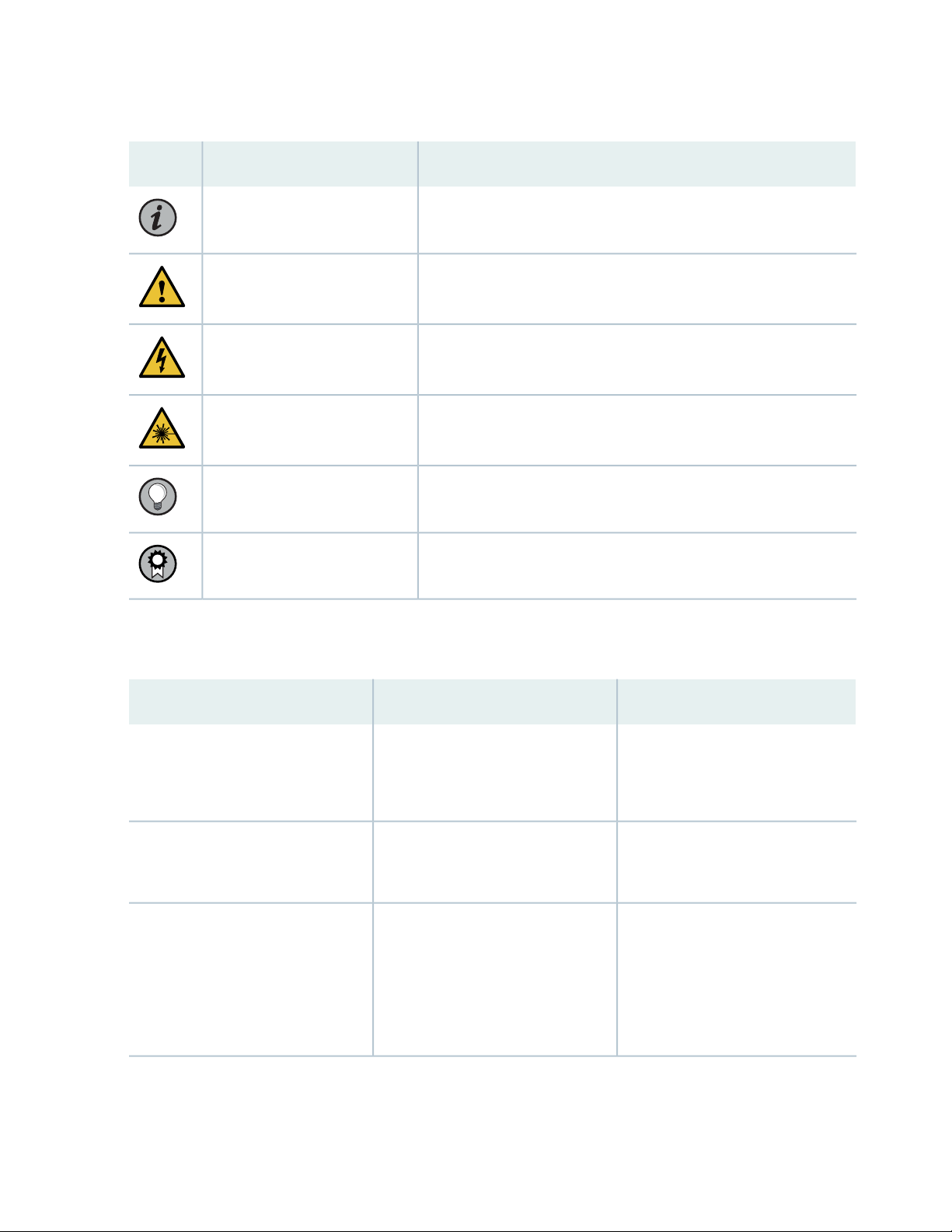
Table 1: Notice Icons
xiv
DescriptionMeaningIcon
Indicates important features or instructions.Informational note
Caution
Indicates a situation that might result in loss of data or hardware
damage.
Alerts you to the risk of personal injury or death.Warning
Alerts you to the risk of personal injury from a laser.Laser warning
Indicates helpful information.Tip
Alerts you to a recommended use or implementation.Best practice
Table 2 on page xiv defines the text and syntax conventions used in this guide.
Table 2: Text and Syntax Conventions
ExamplesDescriptionConvention
Fixed-width text like this
Italic text like this
Represents text that you type.Bold text like this
Represents output that appears on
the terminal screen.
Introduces or emphasizes important
•
new terms.
Identifies guide names.
•
Identifies RFC and Internet draft
•
titles.
To enter configuration mode, type
the configure command:
user@host> configure
user@host> show chassis alarms
No alarms currently active
A policy term is a named structure
•
that defines match conditions and
actions.
Junos OS CLI User Guide
•
RFC 1997, BGP Communities
•
Attribute
Page 15

Table 2: Text and Syntax Conventions (continued)
xv
ExamplesDescriptionConvention
Italic text like this
Text like this
< > (angle brackets)
| (pipe symbol)
Represents variables (options for
which you substitute a value) in
commands or configuration
statements.
Represents names of configuration
statements, commands, files, and
directories; configuration hierarchy
levels; or labels on routing platform
components.
variables.
Indicates a choice between the
mutually exclusive keywords or
variables on either side of the symbol.
The set of choices is often enclosed
in parentheses for clarity.
Configure the machine’s domain
name:
[edit]
root@# set system domain-name
domain-name
To configure a stub area, include
•
the stub statement at the [edit
protocols ospf area area-id]
hierarchy level.
The console port is labeled
•
CONSOLE.
stub <default-metric metric>;Encloses optional keywords or
broadcast | multicast
(string1 | string2 | string3)
# (pound sign)
[ ] (square brackets)
Indention and braces ( { } )
; (semicolon)
GUI Conventions
Indicates a comment specified on the
same line as the configuration
statement to which it applies.
Encloses a variable for which you can
substitute one or more values.
Identifies a level in the configuration
hierarchy.
Identifies a leaf statement at a
configuration hierarchy level.
rsvp { # Required for dynamic MPLS
only
community name members [
community-ids ]
[edit]
routing-options {
static {
route default {
nexthop address;
retain;
}
}
}
Page 16
Table 2: Text and Syntax Conventions (continued)
xvi
ExamplesDescriptionConvention
Bold text like this
> (bold right angle bracket)
Represents graphical user interface
(GUI) items you click or select.
Separates levels in a hierarchy of
menu selections.
In the Logical Interfaces box, select
•
All Interfaces.
To cancel the configuration, click
•
Cancel.
In the configuration editor hierarchy,
select Protocols>Ospf.
Documentation Feedback
We encourage you to provide feedback so that we can improve our documentation. You can use either
of the following methods:
Online feedback system—Click TechLibrary Feedback, on the lower right of any page on the Juniper
•
Networks TechLibrary site, and do one of the following:
Click the thumbs-up icon if the information on the page was helpful to you.
•
Click the thumbs-down icon if the information on the page was not helpful to you or if you have
•
suggestions for improvement, and use the pop-up form to provide feedback.
E-mail—Send your comments to techpubs-comments@juniper.net. Include the document or topic name,
•
URL or page number, and software version (if applicable).
Requesting Technical Support
Technical product support is available through the Juniper Networks Technical Assistance Center (JTAC).
If you are a customer with an active Juniper Care or Partner Support Services support contract, or are
Page 17

covered under warranty, and need post-sales technical support, you can access our tools and resources
online or open a case with JTAC.
JTAC policies—For a complete understanding of our JTAC procedures and policies, review the JTAC User
•
Guide located at https://www.juniper.net/us/en/local/pdf/resource-guides/7100059-en.pdf.
Product warranties—For product warranty information, visit https://www.juniper.net/support/warranty/.
•
JTAC hours of operation—The JTAC centers have resources available 24 hours a day, 7 days a week,
•
365 days a year.
Self-Help Online Tools and Resources
For quick and easy problem resolution, Juniper Networks has designed an online self-service portal called
the Customer Support Center (CSC) that provides you with the following features:
Find CSC offerings: https://www.juniper.net/customers/support/
•
Search for known bugs: https://prsearch.juniper.net/
•
xvii
Find product documentation: https://www.juniper.net/documentation/
•
Find solutions and answer questions using our Knowledge Base: https://kb.juniper.net/
•
Download the latest versions of software and review release notes:
•
https://www.juniper.net/customers/csc/software/
Search technical bulletins for relevant hardware and software notifications:
•
https://kb.juniper.net/InfoCenter/
Join and participate in the Juniper Networks Community Forum:
•
https://www.juniper.net/company/communities/
Create a service request online: https://myjuniper.juniper.net
•
To verify service entitlement by product serial number, use our Serial Number Entitlement (SNE) Tool:
https://entitlementsearch.juniper.net/entitlementsearch/
Creating a Service Request with JTAC
You can create a service request with JTAC on the Web or by telephone.
Visit https://myjuniper.juniper.net.
•
Call 1-888-314-JTAC (1-888-314-5822 toll-free in the USA, Canada, and Mexico).
•
For international or direct-dial options in countries without toll-free numbers, see
https://support.juniper.net/support/requesting-support/.
Page 18

1
CHAPTER
Overview
ACX500 System Overview | 19
ACX500 Chassis | 51
Cooling System and Airflow in ACX500 Routers | 67
ACX500 Power System | 68
Page 19

ACX500 System Overview
IN THIS SECTION
ACX500 Universal Metro Router Overview | 19
ACX500 Routers Hardware and CLI Terminology Mapping | 22
Packet Flow on ACX Series Routers | 28
Protocols and Applications Supported by ACX Series Routers | 29
ACX500 Universal Metro Router Overview
19
IN THIS SECTION
Benefits of the ACX500 Router | 21
Juniper Networks ACX500 Universal Metro Routers are principally designed to provide superior
management for rapid provisioning to the access network. The ACX500 routers support rich Gigabit
Ethernet capabilities for uplink, along with support for Gigabit Ethernet interfaces, in a compact form factor
that is environmentally hardened and passively cooled. Seamless, end-to-end MPLS can be used to address
legacy and emerging requirements to provide the foundation for a converged network that utilizes the
same mobile backhaul infrastructure for business or residential services.
The routers have a built-in Routing Engine and one Packet Forwarding Engine. The Packet Forwarding
Engine has one “pseudo” Flexible PIC Concentrator (FPC 0). Because there is no switching fabric, the single
Packet Forwarding Engine takes care of packet forwarding.
Routing Engine—Provides Layer 3 routing services and network management.
•
Packet Forwarding Engine—Performs Layer 2 and Layer 3 packet switching, route lookups, and packet
•
forwarding.
The Juniper Networks ACX Series Universal MetroRouters are powered by the Junos operating system
(Junos OS), which supports extensive Layer 2 and Layer 3 features, IP and MPLS with traffic engineering,
rich network management, fault management, service monitoring and Operation, Administration, and
Maintenance (OAM) capabilities, and an open software development kit (SDK) system that enables providers
Page 20

to customize and integrate operations with their own management systems. For a list of related Junos OS
documentation, see https://www.juniper.net/documentation/software/junos/.
As part of the mobile backhaul, an ACX Series router at the cell site and an MX Series router at the
aggregation layer provide comprehensive end-to-end Ethernet, MPLS, and OAM features with the one
Junos OS running on both platforms.
20
Page 21

The ACX500 routers can be installed indoors as well as outdoors:
ACX500 indoor—The compact ACX500 indoor routers are one rack unit (U; that is, 1.75 in. or 4.45 cm)
•
tall. Several routers can be stacked in a single floor-to-ceiling rack for increased port density per unit of
floor space. The chassis is a rigid sheet metal structure that houses all the other router components. The
chassis of the ACX500 indoor router measures 1.75 in. (4.45 cm) high, 9.4 in. (24 cm) deep, and
17.5 in. (44.5 cm) wide. The outer edges of the mounting brackets extend the width to 19 in. (48 cm)
(from the front-mounting brackets to the rear of the chassis). The chassis installs in standard 300-mm
deep (or larger) enclosed cabinets, 19-in. equipment racks, or telco open-frame racks.
ACX500 outdoor—The compact ACX500 outdoor routers are environmental hardened, and can be
•
deployed in an outdoor environment, such as on walls and poles. The chassis of the ACX500 indoor
router measures 1.75 in. (4.45 cm) high, 9.4 in. (24 cm) deep, and 17.5 in. (44.5 cm) wide. The chassis of
the ACX500 outdoor router with the Power over Ethernet (PoE) unit measures 16 in. (40.64 cm) high,
4.7 in. (11.93 cm) deep, and 10 in. (25.4 cm) wide. You need to purchase the pole-mounting kit or the
wall-mounting kit from Juniper Networks to mount the router in an outdoor environment.
Benefits of the ACX500 Router
21
Zero Touch Provisioning (ZTP)—ZTP enables quick deployment of a large number of ACX 500 routers.
•
As the ACX500 supports ZTP, it can be production-ready with little or no manual intervention. As
installation and provisioning is faster, overall operational efficiency is improved, and the MPLS deployment
in the access layer is simplified.
Integrated high-precision timing (Synchronous Ethernet and Precision Time Protocol)— You can use
•
the ACX500 routers for Synchronous Ethernet and PTP in a hybrid mode for the highest level of frequency
(10 ppb) and phase (<500 nS) accuracy required for LTE-A. The ACX500, ACX500-O, and ACX500-O-PoE
routers also provide an integrated GPS receiver and can act as a grandmaster (GM) clock for a distributed
PTP implementation, used for the aggregation of small cell traffic when the backhaul is transported over
the Internet.
Advanced security services— ACX500 routers support IPsec, Media Access Control Security (MACsec),
•
Network Address Translation (NAT), and Trusted Platform Module (TPM) features to protect against
potential vulnerabilities to the network as well as subscriber traffic.
Environmentally hardened design—ACX500 routers are temperature hardened and support passive
•
cooling for outdoor deployments in extreme weather conditions. The ACX500-O and ACX500-O-PoE
routers are based on environmentally hardened, ruggedized chassis and are IP65-compliant for outdoor
deployments (pole mount or stand mount) with no need for an enclosure or cabinet.
High availability and reliability— Junos Continuity on ACX500 eliminates OS upgrades and system
•
reboots when new hardware is added to ACX500 routers. A plug-in package provides the drivers and
support files needed to bring the hardware online.
Unified in-service software upgrade (unified ISSU), provides software upgrades between two different
Junos OS releases (major or minor) without disrupting network traffic.
Page 22

ACX500 Routers Hardware and CLI Terminology Mapping
IN THIS SECTION
ACX500 Indoor Routers Hardware and CLI Terminology Mapping | 22
ACX500 Outdoor Routers Hardware and CLI Terminology Mapping | 24
ACX500 Outdoor Routers with PoE Hardware and CLI Terminology Mapping | 26
ACX500 Indoor Routers Hardware and CLI Terminology Mapping
Table 3 on page 22 describes the hardware terms used in ACX500 indoor router documentation and the
corresponding terms used in the Junos OS CLI. Figure 1 on page 24 shows the port locations of the
interfaces.
22
Table 3: CLI Equivalents of Terms Used in Documentation for ACX500 Indoor Routers
Hardware
Item (as
Displayed
in the CLI)
FPC (n)
Description (as
Displayed in the CLI)
Abbreviated name of
the Flexible PIC
Concentrator (FPC)
Value (as Displayed
in the CLI)
Value of n is always
0.
Item in
Documentation
Router chassis–ACX500Chassis
The router does not
have actual FPCs. In
this case, FPC refers to
the router itself.
Additional Information
“Chassis Physical
Specifications for ACX500
Routers” on page 84
Interface Naming
Conventions Used in the
Junos OS Operational
Commands
Page 23

Table 3: CLI Equivalents of Terms Used in Documentation for ACX500 Indoor Routers (continued)
Hardware
Item (as
Displayed
in the CLI)
Description (as
Displayed in the CLI)
Value (as Displayed
in the CLI)
Item in
Documentation
Additional Information
23
PIC (n)
Xcvr (n)
Abbreviated name of
the Physical Interface
Card (PIC)
(COMBO PIC):
4x 1GE (RJ-45 with
•
PoE+ support)
4x 1GE (SFP)
•
Abbreviated name of
the transceiver
n is a value in the
range of 0–1.
PIC 02x 1GE (SFP)
PIC 1One of the following
equivalent to the
number of the port in
which the transceiver
is installed.
The router does not
have actual PIC
devices; see entries for
PIC 0 through PIC 1
for the equivalent item
on the router.
Built-in uplink ports on
the front panel of the
router
Built-in uplink ports on
the front panel of the
router
Optical transceiversn is a value
Interface Naming
Conventions Used in the
Junos OS Operational
Commands
“ACX500 Universal Metro
Router Overview” on
page 19
“ACX500 Universal Metro
Router Overview” on
page 19
“Uplink Ports on ACX500
Routers” on page 63
supply (n)
Fan
Xcvr (n)
Built-in power supplyPower
Fan
NOTE: ACX500routers
are fanless models.
Abbreviated name of
the transceiver
0.
“ACX500 Universal
Metro Router
Overview” on
page 19
equivalent to the
number of the port in
which the transceiver
is installed.
DC power supplyValue of n is always
Optical transceiversn is a value
“ACX500 Power Overview”
on page 68
“Uplink Ports on ACX500
Routers” on page 63
Page 24
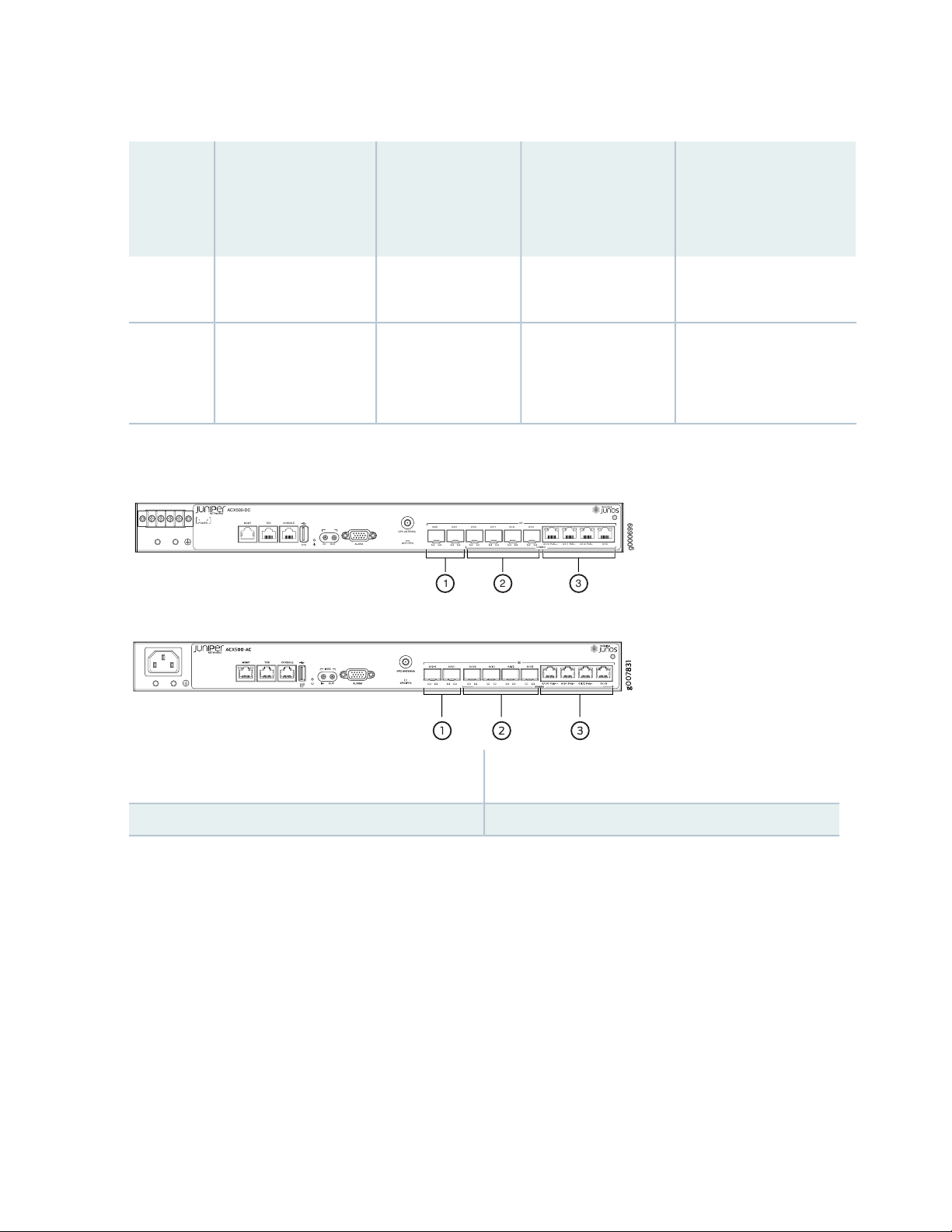
Table 3: CLI Equivalents of Terms Used in Documentation for ACX500 Indoor Routers (continued)
ACX500-DC
0/1/30/1/0 PoE++ 0/1/1 PoE+ 0/1/2 PoE+
0/1/30/1/20/1/10/1/00/0/10/0/0
GE
COMBO
POWER
1 2
SYS
MGMT TOD CONSOLE
GPS1PPS
GPSANTENNA
IN
OUT ALARM
g000699
1 2 3
Hardware
Item (as
Displayed
in the CLI)
Description (as
Displayed in the CLI)
Value (as Displayed
in the CLI)
Item in
Documentation
Additional Information
24
DC power supplyValue of n is always
Fan–Fan
supply (n)
Fan
Built-in power supplyPower
0.
NOTE: ACX500routers
are fanless.
Figure 1: ACX500 Indoor Router Interface Port Mapping—DC and AC Chassis
“ACX500 Power Overview”
on page 68
“Cooling System and
Airflow in ACX500
Routers” on page 67
FPC 0, PIC 0: 0/0/0–0/0/1 (2x1GE SFP)
3—1— FPC 0, PIC 1: 0/1/0 PoE++, 0/1/1 PoE+, 0/1/2 PoE+,
and 0/1/3 (4x1GE RJ-45)
2—FPC 0, PIC 1: 0/1/0–0/1/3 (4x1GE SFP)
ACX500 Outdoor Routers Hardware and CLI Terminology Mapping
Table 4 on page 25 describes the hardware terms used in ACX500 outdoor router documentation and the
corresponding terms used in the Junos OS CLI. Figure 2 on page 26 shows the port locations of the
interfaces.
Page 25

Table 4: CLI Equivalents of Terms Used in Documentation for ACX500 Outdoor Routers
Hardware
Item (as
Displayed
in the CLI)
Description (as
Displayed in the
CLI)
Value (as
Displayed in the
CLI)
Additional InformationItem in Documentation
25
FPC (n)
PIC (n)
Abbreviated name of
the Flexible PIC
Concentrator (FPC)
Abbreviated name of
the Physical Interface
Card (PIC)
Value of n is
always 0.
n is a value in the
range of 0–1.
PIC 03x 1GE (SFP)
PIC 13x 1GE (RJ-45)
Router chassis–ACX500Chassis
The router does not have
actual FPCs. In this case,
FPC refers to the router
itself.
The router does not have
actual PIC devices; see
entries for PIC 0 through
PIC 1 for the equivalent
item on the router.
Built-in uplink ports on
the front panel of the
router
Built-in uplink ports on
the front panel of the
router
“Chassis Physical
Specifications for ACX500
Routers” on page 84
Interface Naming Conventions
Used in the Junos OS
Operational Commands
Interface Naming Conventions
Used in the Junos OS
Operational Commands
“ACX500 Universal Metro
Router Overview” on page 19
“ACX500 Universal Metro
Router Overview” on page 19
Xcvr (n)
supply (n)
Fan
Abbreviated name of
the transceiver
Built-in power supplyPower
NOTE: ACX500
routers are fanless.
equivalent to the
number of the
port in which the
transceiver is
installed.
always 0.
Optical transceiversn is a value
DC power supplyValue of n is
Fan–Fan
“Uplink Ports on ACX500
Routers” on page 63
“ACX500 Power Overview”
on page 68
“Cooling System and Airflow
in ACX500 Routers” on
page 67
Page 26
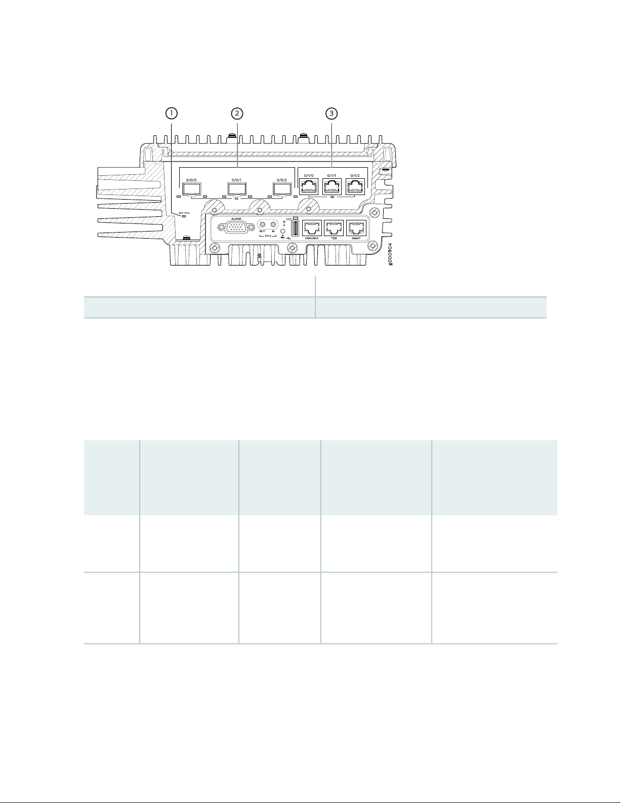
Figure 2: ACX500 Outdoor Router Interface Port Mapping
3—1— FPC 0, PIC 1: 0/1/0–0/1/2 (3x1GE RJ-45)GPS LED
2—FPC 0, PIC 0: 0/0/0–0/0/2 (3x1GE SFP)
26
ACX500 Outdoor Routers with PoE Hardware and CLI Terminology Mapping
Table 5 on page 26 describes the hardware terms used in ACX500 outdoor router with PoE documentation
and the corresponding terms used in the Junos OS CLI. Figure 3 on page 28 shows the port locations of
the interfaces.
Table 5: CLI Equivalents of Terms Used in Documentation for ACX500 Outdoor Routers with PoE
Hardware
Item (as
Displayed
in the CLI)
FPC (n)
Description (as
Displayed in the CLI)
Abbreviated name of
the Flexible PIC
Concentrator (FPC)
Value (as
Displayed in the
CLI)
Value of n is
always 0.
Router chassis–ACX500Chassis
The router does not have
actual FPCs. In this case,
FPC refers to the router
itself.
Additional InformationItemin Documentation
“Chassis Physical
Specifications for ACX500
Routers” on page 84
Interface Naming Conventions
Used in the Junos OS
Operational Commands
Page 27

Table 5: CLI Equivalents of Terms Used in Documentation for ACX500 Outdoor Routers with PoE (continued)
Hardware
Item (as
Displayed
in the CLI)
Description (as
Displayed in the CLI)
Value (as
Displayed in the
CLI)
Additional InformationItemin Documentation
27
PIC (n)
Xcvr (n)
Abbreviated name of
the Physical Interface
Card (PIC)
PoE+ support)
Abbreviated name of
the transceiver
n is a value in the
range of 0–1.
PIC 03x 1GE (SFP)
PIC 13x 1GE (RJ-45 with
equivalent to the
number of the
port in which the
transceiver is
installed.
The router does not have
actual PIC devices; see
entries for PIC 0 through
PIC 1 for the equivalent
item on the router.
Built-in uplink ports on
the front panel of the
router
Built-in uplink ports on
the front panel of the
router
Optical transceiversn is a value
Interface Naming Conventions
Used in the Junos OS
Operational Commands
“ACX500 Universal Metro
Router Overview” on page 19
“ACX500 Universal Metro
Router Overview” on page 19
“Uplink Ports on ACX500
Routers” on page 63
supply (n)
Fan
Built-in power supplyPower
NOTE: ACX500
routers are fanless.
always 0.
DC power supplyValue of n is
Fan–Fan
“ACX500 Power Overview”
on page 68
“Cooling System and Airflow
in ACX500 Routers” on
page 67
Page 28
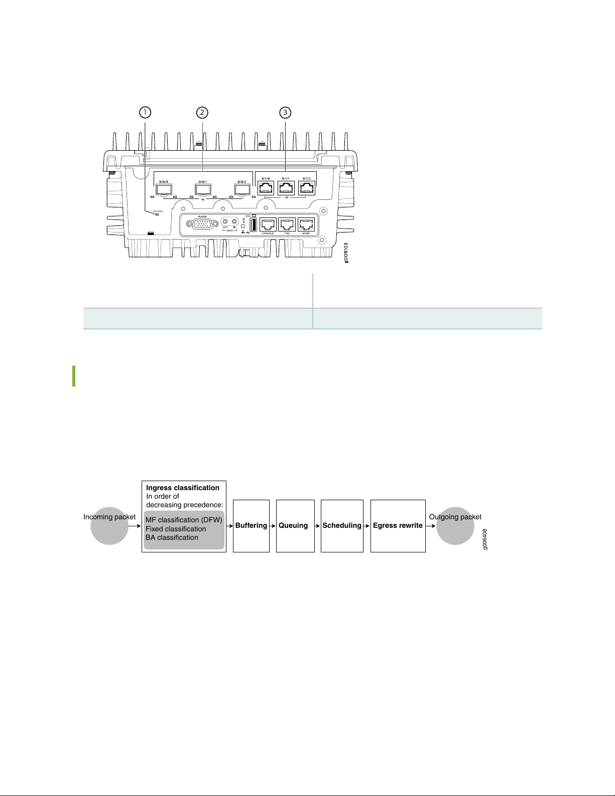
Figure 3: ACX500 Outdoor Router Interface Port Mapping
Incoming packet
Ingress classification
In order of
decreasing precedence:
MF classification (DFW)
Fixed classification
BA classification
Queuing Egress rewrite
Outgoing packet
g006408
Buffering Scheduling
28
GPS LED
3—1— FPC 0, PIC 1: 0/1/0–0/1/2 (3x1GE RJ-45 with PoE+
support)
2—FPC 0, PIC 0: 0/0/0–0/0/2 (3x1GE SFP)
Packet Flow on ACX Series Routers
The class-of-service (CoS) architecture for ACX Series routers is in concept similar to that for MX Series
routers. The general architecture for ACX Series routers is shown in Figure 4 on page 28.
Figure 4: ACX Series Router Packet Forwarding and Data Flow
Based on the model, ACX Series routers contain a built-in Routing Engine and Packet Forwarding Engine
and can contain both T1/E1 and Gigabit Ethernet Ports.
The Packet Forwarding Engine has one or two “pseudo” Flexible PIC Concentrators. Because there is no
switching fabric, the single Packet Forwarding Engine takes care of both ingress and egress packet
forwarding.
Fixed classification places all packets in the same forwarding class, or the usual multifield (MF) or behavior
aggregate (BA) classifications can be used to treat packets differently. BA classification with firewall filters
can be used for classification based on IP precedence, DSCP, IEEE, or other bits in the frame or packet
header.
Page 29
However, the ACX Series routers can also employ multiple BA classifiers on the same physical interface.
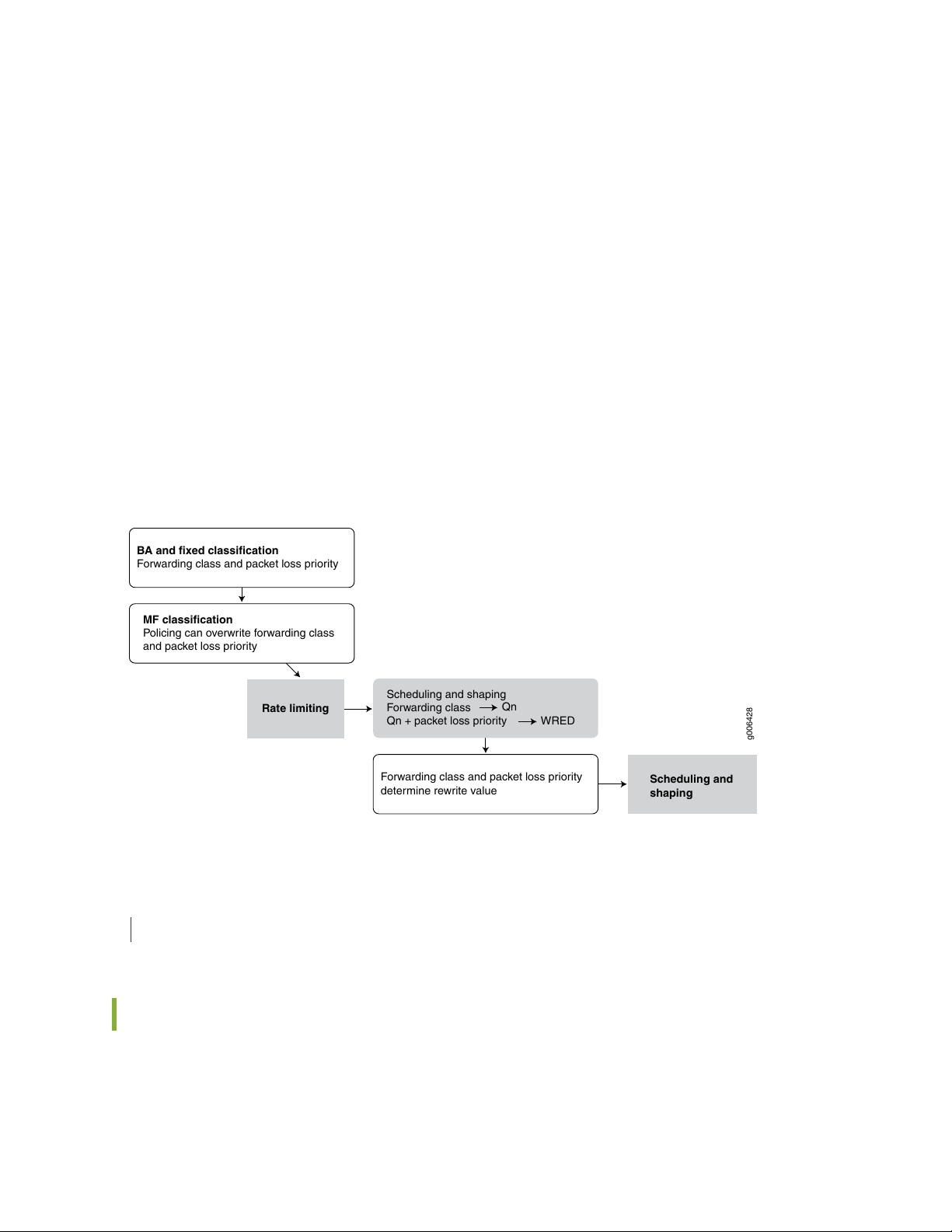
g006428
Rate limiting
BA and fixed classification
Forwarding class and packet loss priority
MF classification
Policing can overwrite forwarding class
and packet loss priority
Forwarding class and packet loss priority
determine rewrite value
Scheduling and
shaping
Scheduling and shaping
Forwarding class
Qn + packet loss priority
Qn
WRED
The physical interfaces do not have to employ the same type of BA classifier. For example, a single physical
interface can use classifiers based on IP precedence as well as IEEE 802.1p. If the CoS bits of interest are
on the inner VLAN tag of a dual-tagged VLAN interface, the classifier can examine either the inner or outer
bits. (By default, the classification is done based on the outer VLAN tag.)
Eight queues per egress port support scheduling using the weighted deficit round- robin (WDRR) mechanism,
a form of round-robin queue servicing. The supported priority levels are strict-high and default (low). The
ACX Series router architecture supports both weighted random early detect (WRED) and weighted tail
drop (WTD).
All CoS features are supported at line rate.
The packet pipeline through an ACX Series router is shown in Figure 5 on page 29. Note that the rate
limiting is done with an integrated architecture along with all other CoS functions. Scheduling and shaping
are supported on the output side.
Figure 5: ACX Series Router Packet Handling
29
SEE ALSO
ACX Series Universal Metro Router Configuration Guide
Protocols and Applications Supported by ACX Series Routers
Table 6 on page 30 contains the first Junos OS Release support for protocols and applications on ACX
Series routers. A dash indicates that the protocol or application is not supported.
Page 30

NOTE:
The [edit logical-systems logical-system-name] hierarchy level is not supported on ACX Series
•
routers.
The ACX Series routers does not support per-family maximum transmission unit (MTU)
•
configuration. The MTU applied to family inet gets applied to other families as well, even
though it can be configured though CLI and visible in show interface extensive output. The
only way to use higher MTU for a family is to manipulate the MTU, apply at interface or family
inet levels, and let it calculate for each family automatically. MTU values are not limited to
1500 but can range between 256 to 9216.
For more information, see the Knowledge Base (KB) article KB28179 at:
https://kb.juniper.net/InfoCenter/index?page=content&id=KB28179.
Table 6: Protocols and Applications Supported by ACX Series Routers
Protocol or
Application
30
ACX5448ACX500ACX5096ACX5048ACX4000ACX2200ACX2100ACX2000ACX1100ACX1000
Interface and Encapsulation Types
10G
only)
interfaces (SAToP,
CESoP)
12.2R212.212.2R212.2Ethernet interfaces—1G,
12.3X54
–D15
-12.2R212.2–12.2Circuit emulation
12.3x51
-D10
––––––Ethernet interfaces—40G
-D10
15.1X54
–D20
15.1X54
–D20
15.1X54
–D20
–D20
–D20
(Indoor)
12.3X54
–D25
(Outdoor)
18.2R112.3X54
18.2R1–15.1X54
––––––12.2R212.2–12.2ATM interfaces (IMA
––––––12.2R212.2–12.2E1 interfaces
––––––12.2R212.2–12.2T1 interfaces
––––12.3x51
Page 31

Table 6: Protocols and Applications Supported by ACX Series Routers (continued)
Protocol or
Application
31
ACX5448ACX500ACX5096ACX5048ACX4000ACX2200ACX2100ACX2000ACX1100ACX1000
Layer 3
–––––SONET/SDH interfaces
-D10
(requires
a
MIC)
12.2R212.212.2R212.2Static routes
12.2R212.212.2R212.2OSPF
12.3X54
–D15
12.3X54
–D15
12.3x51
-D10
12.3x51
-D10
15.1X54
–D20
15.1X54
–D20
15.1X54
–D20
15.1X54
–D20
–D20
(Indoor)
12.3X54
–D25
(Outdoor)
–D20
(Indoor)
12.3X54
–D25
(Outdoor)
––––12.3x51
18.2R112.3X54
18.2R112.3X54
12.2R212.212.2R212.2IS-IS
12.2R212.212.2R212.2BGP
12.3X54
–D15
12.3X54
–D15
12.3x51
-D10
12.3x51
-D10
15.1X54
–D20
15.1X54
–D20
15.1X54
–D20
15.1X54
–D20
–D20
(Indoor)
12.3X54
–D25
(Outdoor)
–D20
(Indoor)
12.3X54
–D25
(Outdoor)
18.2R112.3X54
18.2R112.3X54
Page 32

Table 6: Protocols and Applications Supported by ACX Series Routers (continued)
Protocol or
Application
32
ACX5448ACX500ACX5096ACX5048ACX4000ACX2200ACX2100ACX2000ACX1100ACX1000
Protocol (ICMP)
Protocol (ARP)
Detection (BFD) protocol
12.2R212.212.2R212.2Internet Control Message
12.2R212.212.2R212.2Address Resolution
12.2R212.212.2R212.2Bidirectional Forwarding
12.3X54
–D15
12.3X54
–D15
12.3X54
–D15
12.3x51
-D10
12.3x51
-D10
12.3x51
-D10
15.1X54
–D20
15.1X54
–D20
15.1X54
–D20
15.1X54
–D20
15.1X54
–D20
15.1X54
–D20
–D20
(Indoor)
12.3X54
–D25
(Outdoor)
–D20
(Indoor)
12.3X54
–D25
(Outdoor)
–D20
(Indoor)
12.3X54
–D25
(Outdoor)
18.2R112.3X54
18.2R112.3X54
18.2R112.3X54
Configuration Protocol
(DHCP)
(OSPF, IS-IS)
12.2R212.212.2R212.2Dynamic Host
12.2R212.212.2R212.2IP fast reroute (FRR)
12.3X54
–D15
12.3X54
–D15
12.3x51
-D10
12.3x51
-D10
15.1X54
–D20
15.1X54
–D20
15.1X54
–D20
15.1X54
–D20
–D20
(Indoor)
12.3X54
–D25
(Outdoor)
–D20
(Indoor)
12.3X54
–D25
(Outdoor)
18.2R112.3X54
18.2R112.3X54
Page 33

Table 6: Protocols and Applications Supported by ACX Series Routers (continued)
Protocol or
Application
33
ACX5448ACX500ACX5096ACX5048ACX4000ACX2200ACX2100ACX2000ACX1100ACX1000
unit (MTU) range (256 to
9192)
12.2R212.212.2R212.2Maximum transmission
12.3R112.3R112.3R112.3R1Layer 3 VPNs
12.2R212.212.2R212.2RSVP
12.3X54
–D15
12.3X54
–D15
12.3X54
–D15
12.3x51
-D10
12.3x51
-D10
12.3x51
-D10
15.1X54
–D20
15.1X54
–D20
15.1X54
–D20
15.1X54
–D20
15.1X54
–D20
15.1X54
–D20
–D20
(Indoor)
12.3X54
–D25
(Outdoor)
–D20
(Indoor)
12.3X54
–D25
(Outdoor)
–D20
(Indoor)
12.3X54
–D25
(Outdoor)
18.2R112.3X54
18.2R112.3X54
18.2R112.3X54
MPLS, VPLS, VPNs
path (LSP)
12.2R212.212.2R212.2LDP (targeted and direct)
12.2R212.212.2R212.2Static label-switched
12.3X54
–D15
12.3X54
–D15
12.3x51
-D10
12.3x51
-D10
15.1X54
–D20
15.1X54
–D20
15.1X54
–D20
15.1X54
–D20
–D20
(Indoor)
12.3X54
–D25
(Outdoor)
–D20
(Indoor)
12.3X54
–D25
(Outdoor)
18.2R112.3X54
18.2R112.3X54
Page 34

Table 6: Protocols and Applications Supported by ACX Series Routers (continued)
Protocol or
Application
34
ACX5448ACX500ACX5096ACX5048ACX4000ACX2200ACX2100ACX2000ACX1100ACX1000
12.2R212.212.2R212.2FRR
12.2R212.212.2R212.2Traffic engineering
12.2R212.212.2R212.2E-LINE
12.3X54
–D15
12.3X54
–D15
12.3X54
–D15
12.3x51
-D10
12.3x51
-D10
12.3x51
-D10
15.1X54
–D20
15.1X54
–D20
15.1X54
–D20
15.1X54
–D20
15.1X54
–D20
15.1X54
–D20
–D20
(Indoor)
12.3X54
–D25
(Outdoor)
–D20
(Indoor)
12.3X54
–D25
(Outdoor)
–D20
(Indoor)
12.3X54
–D25
(Outdoor)
18.2R112.3X54
18.2R112.3X54
18.2R112.3X54
Edge to Edge (PWE3
[signaled])
12.2R212.2–12.2Pseudowire Emulation
12.2R212.212.2R212.2Static Ethernet PWs
12.3X54
–D15
12.3X54
–D15
12.3x51
-D10
12.3x51
-D10
15.1X54
–D20
15.1X54
–D20
–D20
15.1X54
–D20
–D20
(Indoor)
12.3X54
–D25
(Outdoor)
18.2R1–15.1X54
18.2R112.3X54
Page 35

Table 6: Protocols and Applications Supported by ACX Series Routers (continued)
Protocol or
Application
35
ACX5448ACX500ACX5096ACX5048ACX4000ACX2200ACX2100ACX2000ACX1100ACX1000
monitoring on active and
standby pseudowires
Ethernet Layer 2
(EFM 802.3ah)
12.2R212.212.2R212.2Layer 2 circuits
12.2R212.212.2R212.2IEE802.1ag CC
12.2R212.212.2R212.2Ethernet in the first mile
12.3X54
–D15
12.3X54
–D15
12.3X54
–D15
12.3x51
-D10
12.3x51
-D10
––––––VPLS
12.3x51
-D10
15.1X54
–D20
15.1X54
–D20
15.1X54
–D20
15.1X54
–D20
15.1X54
–D20
15.1X54
–D20
–D20
15.1X54
–D20
–D20
(Indoor)
12.3X54
–D25
(Outdoor)
–D20
(Indoor)
12.3X54
–D25
(Outdoor)
–D20
(Indoor)
18.2R112.3X54
18.2R112.3X54
18.2R1–15.1X54
18.2R112.3X54
fault management (CFM)
12.3X54
–D25
(Outdoor)
12.2R212.212.2R212.2802.1ag connectivity
12.3X54
–D15
12.3x51
-D10
15.1X54
–D20
15.1X54
–D20
–D20
(Indoor)
12.3X54
–D25
(Outdoor)
18.2R112.3X54
Page 36

Table 6: Protocols and Applications Supported by ACX Series Routers (continued)
Protocol or
Application
36
ACX5448ACX500ACX5096ACX5048ACX4000ACX2200ACX2100ACX2000ACX1100ACX1000
interface-status type,
length, and value (TLV)
QoS
control lists—ACLs)—family
inet
match conditions for MPLS
traffic
12.2R212.212.2R212.2IEE802.1ag
12.2R212.212.2R212.2Firewall filters (access
12.2R212.212.2R212.2Standard firewall filter
12.3X54
–D15
12.3X54
–D15
12.3X54
–D15
12.3x51
-D10
12.3x51
-D10
12.3x51
-D10
15.1X54
–D20
15.1X54
–D20
15.1X54
–D20
15.1X54
–D20
15.1X54
–D20
15.1X54
–D20
–D20
(Indoor)
12.3X54
–D25
(Outdoor)
–D20
(Indoor)
12.3X54
–D25
(Outdoor)
–D20
(Indoor)
18.2R112.3X54
18.2R112.3X54
18.2R112.3X54
ccc/any
12.3X54
–D25
(Outdoor)
12.2R212.212.2R212.2Firewall filters—family
12.2R212.2R112.2R212.2R1Firewall - Port Mirroring
12.3X54
–D15
12.3X54
–D15
12.3x51
-D10
-D10
15.1X54
–D20
15.1X54
–D20
–D20
(Indoor)
12.3X54
–D25
(Outdoor)
18.2R112.3X54
18.2R1-17.1R117.1R112.3x51
Page 37

Table 6: Protocols and Applications Supported by ACX Series Routers (continued)
Protocol or
Application
37
ACX5448ACX500ACX5096ACX5048ACX4000ACX2200ACX2100ACX2000ACX1100ACX1000
interface
interface
12.2R212.212.2R212.2Policing—per logical
12.2R212.212.2R212.2Policing—per physical
12.2R212.212.2R212.2Policing—per family
12.3X54
–D15
12.3X54
–D15
12.3X54
–D15
12.3x51
-D10
12.3x51
-D10
12.3x51
-D10
15.1X54
–D20
15.1X54
–D20
15.1X54
–D20
15.1X54
–D20
15.1X54
–D20
15.1X54
–D20
–D20
(Indoor)
12.3X54
–D25
(Outdoor)
–D20
(Indoor)
12.3X54
–D25
(Outdoor)
–D20
(Indoor)
12.3X54
–D25
(Outdoor)
18.2R112.3X54
18.2R112.3X54
18.2R112.3X54
color blind)
color blind)
12.2R212.212.2R212.2TrTCM (color aware,
12.2R212.212.2R212.2SrTCM (color aware,
12.3X54
–D15
12.3X54
–D15
12.3x51
12.3X54
–D15
-D10
12.3x51
-D10
15.1X54
–D20
15.1X54
–D20
15.1X54
–D20
15.1X54
–D20
–D20
(Indoor)
12.3X54
–D25
(Outdoor)
–D20
(Indoor)
12.3X54
–D25
(Outdoor)
18.2R112.3X54
18.2R112.3X54
Page 38

Table 6: Protocols and Applications Supported by ACX Series Routers (continued)
Protocol or
Application
38
ACX5448ACX500ACX5096ACX5048ACX4000ACX2200ACX2100ACX2000ACX1100ACX1000
12.2R212.212.2R212.2Host protection
12.2R212.212.2R212.2Eight queues per port
12.2R212.212.2R212.2Priority queuing
12.3X54
–D15
12.3X54
–D15
12.3X54
–D15
12.3x51
-D10
12.3x51
-D10
12.3x51
-D10
15.1X54
–D20
15.1X54
–D20
15.1X54
–D20
15.1X54
–D20
15.1X54
–D20
15.1X54
–D20
–D20
(Indoor)
12.3X54
–D25
(Outdoor)
–D20
(Indoor)
12.3X54
–D25
(Outdoor)
–D20
(Indoor)
12.3X54
–D25
(Outdoor)
18.2R112.3X54
18.2R112.3X54
18.2R112.3X54
different priorities
12.2R212.212.2R212.2Rate control
12.2R212.212.2R212.2Scheduling with two
12.3X54
–D15
12.3X54
–D15
12.3x51
-D10
12.3x51
-D10
15.1X54
–D20
15.1X54
–D20
15.1X54
–D20
15.1X54
–D20
–D20
(Indoor)
12.3X54
–D25
(Outdoor)
–D20
(Indoor)
12.3X54
–D25
(Outdoor)
18.2R112.3X54
18.2R112.3X54
Page 39

Table 6: Protocols and Applications Supported by ACX Series Routers (continued)
Protocol or
Application
39
ACX5448ACX500ACX5096ACX5048ACX4000ACX2200ACX2100ACX2000ACX1100ACX1000
detection (WRED) drop
profile (DP)
12.2R212.212.2R212.2Low-latency queue (LLQ)
12.2R212.212.2R212.2Weighted random early
12.2R212.212.2R212.2Classification—DSCP
12.3X54
–D15
12.3X54
–D15
12.3X54
–D15
12.3x51
-D10
12.3x51
-D10
12.3x51
-D10
15.1X54
–D20
15.1X54
–D20
15.1X54
–D20
15.1X54
–D20
15.1X54
–D20
15.1X54
–D20
–D20
(Indoor)
12.3X54
–D25
(Outdoor)
–D20
(Indoor)
12.3X54
–D25
(Outdoor)
–D20
(Indoor)
12.3X54
–D25
(Outdoor)
18.2R112.3X54
18.2R112.3X54
18.2R112.3X54
802.1p
12.2R212.212.2R212.2Classification—MPLS EXP
12.2R212.212.2R212.2Classification—IEEE
12.3X54
–D15
12.3X54
–D15
12.3x51
-D10
12.3x51
-D10
15.1X54
–D20
15.1X54
–D20
15.1X54
–D20
15.1X54
–D20
–D20
(Indoor)
12.3X54
–D25
(Outdoor)
–D20
(Indoor)
12.3X54
–D25
(Outdoor)
18.2R112.3X54
18.2R112.3X54
Page 40

Table 6: Protocols and Applications Supported by ACX Series Routers (continued)
Protocol or
Application
40
ACX5448ACX500ACX5096ACX5048ACX4000ACX2200ACX2100ACX2000ACX1100ACX1000
12.2R212.212.2R212.2Rewrite—DSCP
12.2R212.212.2R212.2Rewrite MPLS EXP
12.2R212.212.2R212.2Rewrite 802.1p
12.3X54
–D15
12.3X54
–D15
12.3X54
–D15
12.3x51
-D10
12.3x51
-D10
12.3x51
-D10
15.1X54
–D20
15.1X54
–D20
15.1X54
–D20
15.1X54
–D20
15.1X54
–D20
15.1X54
–D20
–D20
(Indoor)
12.3X54
–D25
(Outdoor)
–D20
(Indoor)
12.3X54
–D25
(Outdoor)
–D20
(Indoor)
12.3X54
–D25
(Outdoor)
18.2R112.3X54
18.2R112.3X54
18.2R112.3X54
to different values
Timing
1588-2008–backup
clock
12.2R212.212.2R212.2Rewrite MPLS and DSCP
12.2R212.212.2R212.2Timing-1588-v2,
12.3X54
–D15
12.3X54
–D15
12.3x51
-D10
-D10
15.1X54
–D20
15.1X54
–D20
––12.3x51
–D20
(Indoor)
12.3X54
–D25
(Outdoor)
–D20
(Indoor)
12.3X54
–D25
(Outdoor)
18.2R112.3X54
18.2R112.3X54
Page 41

Table 6: Protocols and Applications Supported by ACX Series Routers (continued)
Protocol or
Application
41
ACX5448ACX500ACX5096ACX5048ACX4000ACX2200ACX2100ACX2000ACX1100ACX1000
timing supply (BITS)
12.2R212.212.2R212.2Synchronous Ethernet
12.2R212.212.2R212.2Building-integrated
12.2R212.212.2R212.2Clock synchronization
12.3X54
–D15
12.3X54
–D15
12.3X54
–D15
-D10
-D10
-D10
––12.3x51
–D20
(Indoor)
12.3X54
–D25
(Outdoor)
––12.3x51
–D20
(Indoor)
12.3X54
–D25
(Outdoor)
––12.3x51
–D20
(Indoor)
12.3X54
–D25
(Outdoor)
18.2R112.3X54
-12.3X54
-12.3X54
(multiple 1588 primaries)
OAM, Troubleshooting, Manageability, Lawful Intercept
-–––––––––Redundant clock
––––––Transparent clock
15.1X54
–D20
–D20
––––––––Grand Primary Clock
–D20
and
17.3R1
(Indoor)
12.3X54
–D25
(Outdoor)
18.2R1–15.1X54
-12.3X54
Page 42

Table 6: Protocols and Applications Supported by ACX Series Routers (continued)
Protocol or
Application
42
ACX5448ACX500ACX5096ACX5048ACX4000ACX2200ACX2100ACX2000ACX1100ACX1000
(NTP)
12.2R212.212.2R212.2Network Time Protocol
12.2R212.212.2R212.2SNMP
12.2R212.212.2R212.2802.1ag CFM
12.3X54
–D15
12.3X54
–D15
12.3X54
–D15
12.3x51
-D10
12.3x51
-D10
12.3x51
-D10
15.1X54
–D20
15.1X54
–D20
15.1X54
–D20
15.1X54
–D20
15.1X54
–D20
15.1X54
–D20
–D20
(Indoor)
12.3X54
–D25
(Outdoor)
–D20
(Indoor)
12.3X54
–D25
(Outdoor)
–D20
(Indoor)
12.3X54
–D25
(Outdoor)
18.2R112.3X54
18.2R112.3X54
18.2R112.3X54
Performance
Management
12.2R212.212.2R212.2802.3ah LFM
12.2R212.212.2R212.2Y.1731 Fault and
12.3X54
–D15
12.3X54
–D15
12.3x51
-D10
12.3x51
-D10
15.1X54
–D20
15.1X54
–D20
15.1X54
–D20
15.1X54
–D20
–D20
(Indoor)
12.3X54
–D25
(Outdoor)
–D20
(Indoor)
12.3X54
–D25
(Outdoor)
18.2R112.3X54
18.2R112.3X54
Page 43

Table 6: Protocols and Applications Supported by ACX Series Routers (continued)
Protocol or
Application
43
ACX5448ACX500ACX5096ACX5048ACX4000ACX2200ACX2100ACX2000ACX1100ACX1000
12.2R212.212.2R212.2MPLS OAM
12.2R212.212.2R212.2RMON
12.2R212.212.2R212.2Layer 2 traceroute
12.3X54
–D15
12.3X54
–D15
12.3X54
–D15
12.3x51
-D10
12.3x51
-D10
12.3x51
-D10
15.1X54
–D20
15.1X54
–D20
15.1X54
–D20
15.1X54
–D20
15.1X54
–D20
15.1X54
–D20
–D20
(Indoor)
12.3X54
–D25
(Outdoor)
–D20
(Indoor)
12.3X54
–D25
(Outdoor)
–D20
(Indoor)
12.3X54
–D25
(Outdoor)
18.2R112.3X54
18.2R112.3X54
18.2R112.3X54
downloads
12.2R212.212.2R212.2DNS
12.2R212.212.2R212.2TFTP for software
12.3X54
–D15
12.3X54
–D15
12.3x51
-D10
12.3x51
-D10
15.1X54
–D20
15.1X54
–D20
15.1X54
–D20
15.1X54
–D20
–D20
(Indoor)
12.3X54
–D25
(Outdoor)
–D20
(Indoor)
12.3X54
–D25
(Outdoor)
18.2R112.3X54
18.2R112.3X54
Page 44

Table 6: Protocols and Applications Supported by ACX Series Routers (continued)
Protocol or
Application
44
ACX5448ACX500ACX5096ACX5048ACX4000ACX2200ACX2100ACX2000ACX1100ACX1000
mirroring)
12.2R212.212.2R212.2Port mirroring (local port
12.2R212.212.2R212.2Interface loopback
12.2R212.212.2R212.2Ethernet loopback
12.3X54
–D15
12.3X54
–D15
12.3X54
–D15
-D10
12.3x51
-D10
-D10
15.1X54
–D20
––12.3x51
15.1X54
–D20
––12.3x51
–D20
(Indoor)
12.3X54
–D25
(Outdoor)
–D20
(Indoor)
12.3X54
–D25
(Outdoor)
–D20
(Indoor)
12.3X54
–D25
(Outdoor)
18.2R112.3X54
18.2R112.3X54
-12.3X54
stats
12.2R212.212.2R212.2Interface byte and packet
12.2R212.212.2R212.2Interface queue stats
12.3X54
–D15
12.3X54
–D15
12.3x51
-D10
12.3x51
-D10
15.1X54
–D20
15.1X54
–D20
15.1X54
–D20
15.1X54
–D20
–D20
(Indoor)
12.3X54
–D25
(Outdoor)
–D20
(Indoor)
12.3X54
–D25
(Outdoor)
18.2R112.3X54
18.2R112.3X54
Page 45

Table 6: Protocols and Applications Supported by ACX Series Routers (continued)
Protocol or
Application
45
ACX5448ACX500ACX5096ACX5048ACX4000ACX2200ACX2100ACX2000ACX1100ACX1000
connection by VLAN-ID
passive-monitor-mode
12.2R212.212.2R212.2Drop packet stats
12.2R212.212.2R212.2Distinguish each 802.1ag
12.2R212.212.2R212.2Interface
12.3X54
–D15
12.3X54
–D15
12.3X54
–D15
12.3x51
-D10
12.3x51
-D10
12.3x51
-D10
15.1X54
–D20
15.1X54
–D20
15.1X54
–D20
15.1X54
–D20
15.1X54
–D20
15.1X54
–D20
–D20
(Indoor)
12.3X54
–D25
(Outdoor)
–D20
(Indoor)
12.3X54
–D25
(Outdoor)
–D20
(Indoor)
12.3X54
–D25
(Outdoor)
18.2R112.3X54
18.2R112.3X54
18.2R112.3X54
Security
––––––––Multipacket mirror
–D20
(Indoor)
12.3X54
–D25
(Outdoor)
12.2R212.212.2R212.2TACACS AAA
12.3X54
–D15
12.3x51
-D10
15.1X54
–D20
15.1X54
–D20
–D20
(Indoor)
12.3X54
–D25
(Outdoor)
-12.3X54
18.2R112.3X54
Page 46

Table 6: Protocols and Applications Supported by ACX Series Routers (continued)
Protocol or
Application
46
ACX5448ACX500ACX5096ACX5048ACX4000ACX2200ACX2100ACX2000ACX1100ACX1000
prevention
High Availability
12.2R212.212.2R212.2RADIUS authentication
12.2R212.212.2R212.2Control plane DOS
12.2R212.212.2R212.2MPLS FRR
12.3X54
–D15
12.3X54
–D15
12.3X54
–D15
12.3x51
-D10
12.3x51
-D10
12.3x51
-D10
15.1X54
–D20
15.1X54
–D20
15.1X54
–D20
15.1X54
–D20
15.1X54
–D20
15.1X54
–D20
–D20
(Indoor)
12.3X54
–D25
(Outdoor)
–D20
(Indoor)
12.3X54
–D25
(Outdoor)
–D20
(Indoor)
18.2R112.3X54
18.2R112.3X54
18.2R112.3X54
ATM Transport
12.3X54
–D25
(Outdoor)
12.2R212.212.2R212.2BFD
12.2R212.2–12.2ATM over PWE3
12.3X54
–D15
12.3X54
–D15
12.3x51
-D10
-D10
15.1X54
–D20
15.1X54
–D20
–D20
(Indoor)
12.3X54
–D25
(Outdoor)
18.2R112.3X54
-–––12.3x51
Page 47

Table 6: Protocols and Applications Supported by ACX Series Routers (continued)
Protocol or
Application
47
ACX5448ACX500ACX5096ACX5048ACX4000ACX2200ACX2100ACX2000ACX1100ACX1000
encapsulation: S6.1 ATM
N to one cell mode
(required as per standard)
AAL5 SDU encapsulation
(optional)
12.2R212.212.2R212.2RFC4717 ATM
12.2R212.212.2R212.2RFC4717: S6.3—ATM
12.2R212.212.2R212.2ATM PWE3 control word
12.3X54
–D15
12.3X54
–D15
12.3X54
–D15
-D10
-D10
-D10
––12.3x51
–D20
(Indoor)
12.3X54
–D25
(Outdoor)
––12.3x51
–D20
(Indoor)
12.3X54
–D25
(Outdoor)
––12.3x51
–D20
(Indoor)
12.3X54
–D25
(Outdoor)
-12.3X54
-12.3X54
-12.3X54
dynamic labels
12.2R212.212.2R212.2ATM PWE3 by means of
12.2R212.212.2R212.2ATM VPI/VCI swapping
12.3X54
–D15
12.3X54
–D15
-D10
-D10
––12.3x51
–D20
(Indoor)
12.3X54
–D25
(Outdoor)
––12.3x51
–D20
(Indoor)
12.3X54
–D25
(Outdoor)
-12.3X54
-12.3X54
Page 48

Table 6: Protocols and Applications Supported by ACX Series Routers (continued)
Protocol or
Application
48
ACX5448ACX500ACX5096ACX5048ACX4000ACX2200ACX2100ACX2000ACX1100ACX1000
suppression
PW promiscuous mode:
1 PW per port and 1 PW
per VPI
30 cells per packet)
12.2R212.212.2R212.2ATM idle/unassigned cell
12.2R212.212.2R212.2ATM support for N to 1
12.2R212.212.2R212.2Cell concatenation (1 to
12.3X54
–D15
12.3X54
–D15
12.3X54
–D15
-D10
-D10
-D10
––12.3x51
–D20
(Indoor)
12.3X54
–D25
(Outdoor)
––12.3x51
–D20
(Indoor)
12.3X54
–D25
(Outdoor)
––12.3x51
–D20
(Indoor)
12.3X54
–D25
(Outdoor)
-12.3X54
-12.3X54
-12.3X54
VP and VC
ATM (IMA)
ATM Encapsulation
12.2R212.212.2R212.2Packet/byte counters per
12.2R212.212.2R212.2Inverse multiplexing over
12.3X54
–D15
12.3X54
–D15
-D10
-D10
––12.3x51
–D20
(Indoor)
12.3X54
–D25
(Outdoor)
––12.3x51
–D20
(Indoor)
12.3X54
–D25
(Outdoor)
-12.3X54
-12.3X54
Page 49

Table 6: Protocols and Applications Supported by ACX Series Routers (continued)
Protocol or
Application
49
ACX5448ACX500ACX5096ACX5048ACX4000ACX2200ACX2100ACX2000ACX1100ACX1000
relay)
ATM Queuing
(CBR, nrt-VBR, UBR) to
the UNI
categories to PW EXP
bits
12.2R212.212.2R212.2AAL5 SDU (n-to-1 cell
12.2R212.212.2R212.2ATM service categories
12.2R212.212.2R212.2MAP ATM service
12.3X54
–D15
12.3X54
–D15
12.3X54
–D15
-D10
-D10
-D10
––12.3x51
–D20
(Indoor)
12.3X54
–D25
(Outdoor)
––12.3x51
–D20
(Indoor)
12.3X54
–D25
(Outdoor)
––12.3x51
–D20
(Indoor)
-12.3X54
-12.3X54
-12.3X54
12.3X54
–D25
(Outdoor)
12.2R212.212.2R212.2Input policing per VC
12.2R212.212.2R212.2VC output shaping
12.3X54
–D15
12.3X54
–D15
-D10
-D10
––12.3x51
–D20
(Indoor)
12.3X54
–D25
(Outdoor)
––12.3x51
–D20
(Indoor)
12.3X54
–D25
(Outdoor)
-12.3X54
-12.3X54
Page 50

Table 6: Protocols and Applications Supported by ACX Series Routers (continued)
Protocol or
Application
50
ACX5448ACX500ACX5096ACX5048ACX4000ACX2200ACX2100ACX2000ACX1100ACX1000
MIBs
enterprise-specific MIBs
12.2R212.212.2R212.2Early packet discard
12.2R212.212.2R212.2Standard SNMP MIBs
12.2R212.212.2R212.2Juniper Networks
12.3X54
–D15
12.3X54
–D15
12.3X54
–D15
-D10
12.3x51
-D10
12.3x51
-D10
15.1X54
–D20
15.1X54
–D20
––12.3x51
15.1X54
–D20
15.1X54
–D20
–D20
(Indoor)
12.3X54
–D25
(Outdoor)
–D20
(Indoor)
12.3X54
–D25
(Outdoor)
–D20
(Indoor)
-12.3X54
18.2R112.3X54
18.2R112.3X54
SEE ALSO
ACX Series Universal Metro Routers
12.3X54
–D25
(Outdoor)
Page 51

ACX500 Chassis
IN THIS SECTION
ACX500 Indoor Router Description | 51
ACX500 Outdoor Router Description | 52
ACX500 Outdoor Router with PoE Description | 54
Front Panel of an ACX500 Indoor Router | 55
Front Panel of an ACX500 Outdoor Router with PoE | 57
Alarm Contact Port on ACX500 Routers | 59
LEDs on ACX500 Routers | 61
Uplink Ports on ACX500 Routers | 63
Clocking Ports on ACX500 Routers | 66
51
ACX500 Indoor Router Description
The ACX500 indoor routers contain a total of 10 ports that support 1-Gbps speed, eight of which are
labeled COMBO. At any point of time, you can use a maximum of six ports.
The ports labeled COMBO (combination ports) consist of four Gigabit Ethernet ports that support RJ-45
connectors and four Gigabit Ethernet ports that support small form-factor pluggable (SFP) transceivers.
Out of the four RJ-45 ports, three ports support Power over Ethernet (PoE+ and PoE++).
The two ports that are not part of the COMBO ports are Gigabit Ethernet SFP ports.
On the ACX500, the six ports that you can use at any point of time can be two Gigabit Ethernet SFP ports
(non-combination) and four ports from the COMBO ports.
NOTE: You can mix and match the four RJ-45 and SFP COMBO ports as long as the port numbers
are unique.
For example, from the COMBO ports, you can use the 0/1/0 SFP port along with the 0/1/1
PoE+ RJ-45 port, but not the 0/1/0 PoE++ RJ-45 port, as the port numbers of the SFP and the
RJ-45 ports are same (0/1/0).
Page 52

Figure 6 on page 52 and Figure 7 on page 52 shows the front views of the AC-powered and the DC-powered
ACX500 indoor routers.
Figure 6: Front View of the ACX500 Indoor Routers—AC Powered
Figure 7: Front View of the ACX500 Indoor Routers—DC Powered
52
Figure 8 on page 52 shows the rear view of the AC-powered and the DC-powered ACX500 indoor routers.
Figure 8: Rear View of the ACX500 Indoor Router
NOTE: The top view and bottom view of an AC-powered ACX500 router are respectively the
same as those of a DC-powered router. The only component that appears different is the power
inlet for the two routers.
ACX500 Outdoor Router Description
The ACX500 outdoor routers contain three Gigabit Ethernet ports that support SFP transceivers and three
Gigabit Ethernet ports that support RJ-45 connectors. The ACX500 outdoor routers install on a pole or a
wall, with the chassis installed in a vertical orientation with the cables pointing downward and the eye bolt
for hoisting the router pointing upward.
Page 53

Figure 9 on page 53 and Figure 10 on page 53 show the ACX500 outdoor router from bottom and top.
Figure 9: Bottom View of the ACX500 Outdoor Router
3—1— Management port chamber with weather seal coverInterface port chamber with weather seal cover
53
4—2— Power port with weather seal capCable connector ports with weather seal cap
Figure 10: Top View of the ACX500 Outdoor Router
2—1— Eye boltGPS antenna port
NOTE: The top view and bottom view of an AC-powered ACX500 router are respectively the
same as those of a DC-powered router. The only component that appears different is the power
inlet for the two routers.
Page 54

ACX500 Outdoor Router with PoE Description
The ACX500 outdoor routers with Power over Ethernet (PoE) contain three Gigabit Ethernet RJ-45 ports
that support PoE+ and three Gigabit Ethernet SFP ports. Out of the three RJ-45 ports, the port labeled
0/1/0 supports PoE++, and the ports labeled 0/1/1 and 0/1/2 support PoE+ with a maximum system PoE
power limit of 80 W. The ACX500 outdoor routers with PoE install on a pole or a wall, with the chassis
installed in a vertical orientation with the cables pointing downward and the eye bolt for hoisting the router
pointing upward.
Figure 11 on page 54 and Figure 12 on page 55 show the ACX500 outdoor router with PoE from bottom
and top.
Figure 11: Bottom View of the ACX500 Outdoor Router with PoE
54
3—1— Management port chamber with weather seal coverInterface port chamber with weather seal cover
4—2— Power port with weather seal capCable connector ports with weather seal cap
Page 55

Figure 12: Top View of the ACX500 Outdoor Router with PoE
2—1— Eye boltGPS antenna port
NOTE: The top view and bottom view of an AC-powered ACX500 router are respectively the
same as those of a DC-powered router. The only component that appears different is the power
inlet for the two routers.
55
Front Panel of an ACX500 Indoor Router
The front panel of an ACX500 indoor router consists of the following components (see Figure 13 on page 56
and Figure 14 on page 57):
Chassis status LED labeled SYS
•
Power inlet
•
USB port for upgrading Junos OS
•
Management Ethernet port labeled MGMT
•
Time of day (TOD) RJ-45 port
•
Console port labeled CONSOLE
•
Alarm contact port labeled ALARM—accepts a DE-15 alarm cable
•
GPS antenna port labeled GPS ANTENNA
•
External clocking 1 PPS input and output ports labeled IN and OUT
•
Page 56

GPS clocking LED labeled GPS 1PPS
•
Network ports and corresponding status LEDs:
•
Two Gigabit Ethernet SFP ports labeled 0/0/0 and 0/0/1
•
Combination Gigabit Ethernet ports labeled 0/1/0 through 0/1/3, which can be either of the following
•
configurations:
Four Gigabit Ethernet RJ-45 ports.
•
Out of the four RJ-45 ports, three are PoE ports labeled 0/1/0 PoE++, 0/1/1 PoE+ and 0/1/2 PoE+
that provide electrical current to devices through network cables. These ports comply with IEEE
802.3af (PoE) and IEEE 802.3at (PoE+). The PoE++ (ge-0/1/0) port support 65 W, and the PoE+
ports (ge-0/1/1 through ge-0/1/2) support 35 W power. The total PoE power supported for these
three ports is 80 W.
Four Gigabit Ethernet ports, labeled 0/1/0 through 0/1/3, that accept SFP transceivers
•
Figure 13: Front Panel of the ACX500 Indoor Router—AC Chassis
56
9—1— ESD pointAC appliance inlet
10—2— Gigabit Ethernet RJ-45 ports (COMBO)Management Ethernet port (MGMT)
11—3— Gigabit Ethernet SFP ports (COMBO)Time of day (TOD) RJ-45 port
12—4— Gigabit Ethernet SFP portsConsole port (CONSOLE)
13—5— GPS LED (GPS 1PPS)USB port
14—6— External clocking portsRecovery switch
15—7— System status LED (SYS)Alarm contact port
16—8— Grounding terminalsGPS antenna port
Page 57

Figure 14: Front Panel of the ACX500 Indoor Router—DC Chassis
10—1— ESD pointDC terminals
11—2— Gigabit Ethernet RJ-45 ports (COMBO)DC power status LED
12—3— Gigabit Ethernet SFP ports (COMBO)Management Ethernet port (MGMT)
13—4— Gigabit Ethernet SFP portsTime of day (TOD) RJ-45 port
14—5— GPS LED (GPS 1PPS)Console port (CONSOLE)
15—6— External clocking portsUSB port
16—7— System status LED (SYS)Recovery switch
57
17—8— Grounding terminalsAlarm contact port
9—GPS antenna port
Front Panel of an ACX500 Outdoor Router with PoE
The front panel of an ACX500 outdoor router with PoE consists of the following components (see
Figure 15 on page 58, Figure 16 on page 58, and Figure 17 on page 59):
Chassis status LED labeled SYS
•
USB port for upgrading Junos OS
•
Management Ethernet port labeled MGMT
•
Time of day (TOD) RJ-45 port
•
Console port labeled CONSOLE
•
Alarm contact port labeled ALARM—accepts a DE-15 alarm cable
•
External clocking 1 PPS input and out ports labeled IN and OUT
•
GPS clocking LED labeled GPS 1PPS
•
Network ports and corresponding status LEDs:
•
Three Gigabit Ethernet SFP ports labeled 0/0/0 through 0/0/2
•
Three Gigabit Ethernet RJ-45 ports (with PoE+ support) labeled 0/1/0 through 0/1/2
•
Page 58

Figure 15: Front Panel of the ACX500 Outdoor Router with PoE
2—1— Management portsInterface ports
Figure 16 on page 58 shows the ports that are available under the management port cover.
58
Figure 16: Front Panel of the ACX500 Outdoor Router with PoE—Management Ports
6—1— System status LED (SYS)Alarm contact port
7—2— Console port (CONSOLE)External clocking ports
8—3— Time of day (TOD) RJ-45 portRecovery switch
9—4— Management Ethernet port (MGMT)ESD point
5—USB port
Figure 17 on page 59 shows the ports that are available under the interface port cover.
Page 59

Figure 17: Front Panel of the ACX500 Outdoor Router with PoE—Interface Ports
59
GPS LED
2—Gigabit Ethernet SFP ports and LEDs
3—1— Gigabit Ethernet RJ-45 ports (with PoE+ support) and
LEDs
Alarm Contact Port on ACX500 Routers
The ACX500 router has four external alarm contacts (also known as potential free contacts) for connecting
the router to external alarm devices. The port labeled ALARM uses a 15-pin D-type connector. The external
alarm contact has 15 pins that accept a single core wire from external alarm devices. A DE15 alarm cable
is required to connect the ACX500 router to external alarm devices. Use the gauge wire appropriate for
the external device that you are connecting.
Whenever a system condition triggers an alarm, the alarm relay contacts are activated, which in turn
activates the external alarm devices. The alarm setting is open or closed.
You can connect and configure two output alarms and four input alarms. Two additional output alarms
are reserved and are used to indicate major and minor system alarms. Each output and input alarm has
two contacts for connecting the router to external alarm devices. Contact 1 of each alarm can be configured
as Normally Open [NO] or Normally Closed [NC] through the CLI. Contact 2 of each alarm functions as a
reference [REF] or negative potential terminal for Contact 1 of the corresponding alarm and provides a
current path for external alarm devices. Table 7 on page 60 describes the functions of the alarm contacts.
Page 60

Table 7: Alarm Relay Contact Functions
60
FunctionContact NameContact Name
Normally Open (NO)Contact 1
Normally Closed (NC)
Reference (REF)Contact 2
Current is not flowing through Contact 1 and Contact 2 [REF] when
operating normally. When the current flows, the closed alarm is
generated.
Current is flowing through Contact 1 and Contact 2 [REF] when
operating normally. When the current stops flowing, the open alarm
is generated.
Provides the current path for the external alarm-reporting device
and functions as a reference or negative potential terminal for
Contact 1.
Figure 18 on page 60 shows an example of a wiring diagram for a simple output alarm-reporting device.
In this case the device is a light bulb that illuminates when the device encounters a condition that activates
the red alarm LED and relay contacts. The alarm relay contacts can also be used to activate other devices
such as bells or buzzers.
Figure 18: Sample Output Alarm-Reporting Device
Figure 19 on page 61 shows an example of a wiring diagram for a simple input alarm-reporting device. In
this case the push button switch is an alarm sensor that triggers an input alarm when a door-open condition
occurs.
Page 61

Figure 19: Sample Input Alarm-Reporting Device
SEE ALSO
Alarm Contact Port Pinouts for ACX500 Routers | 95
61
LEDs on ACX500 Routers
IN THIS SECTION
System LED on the Front Panel | 61
Gigabit Ethernet SFP and RJ-45 Port LEDs | 62
Management Port LEDs on the Front Panel | 62
GPS 1 PPS LED on the Front Panel | 63
System LED on the Front Panel
One bicolor LED labeled SYS indicates the status of the router. Table 8 on page 62 describes the system
LED in more detail.
Page 62

Table 8: System LED on the Front Panel
DescriptionStateColorLabel
The router is transitioning online.BlinkingGreenSYS
The router is functioning normally.On
steadily
The router has reported a yellow alarm.BlinkingRed
The router has reported a red alarm.On
steadily
Gigabit Ethernet SFP and RJ-45 Port LEDs
Each Gigabit Ethernet SFP and RJ-45 port on the front panel of the router has one pair of port LEDs.
Table 9 on page 62 describes the LEDs in more detail.
62
Table 9: Ethernet Port LEDs
DescriptionStateColorLocationName
The port is receiving data.BlinkingGreenLeftActivity
The port is not receiving data.Off–
The link is online.OnYellowRightLink
No link.Off–
Management Port LEDs on the Front Panel
The RJ-45 port labeled MGMT has a pair of LEDs that display the status of the port. Table 10 on page 62
describes the LEDs in more detail.
Table 10: Management LEDs
DescriptionStateColorLocationName
The port is active and receiving data.BlinkingGreenLeftActivity
The port is not receiving data.Off–
Page 63

Table 10: Management LEDs (continued)
DescriptionStateColorLocationName
The link is online.OnYellowRightLink
No link.Off–
GPS 1 PPS LED on the Front Panel
One green LED labeled GPS 1PPS indicates the status of the pulse per second (PPS) signal received from
the GPS receiver. Table 11 on page 63 describes the LED in more detail.
Table 11: GPS 1 PPS LED on the Front Panel
DescriptionStateColorLabel
PPS signal not received from GPS receiver.OffGreenGPS 1PPS
63
PPS signal received from GPS receiver.Blinking
SEE ALSO
Troubleshooting Resources for ACX500 Routers | 188
Alarm Types and Severity Classes on ACX Series Routers | 189
Uplink Ports on ACX500 Routers
IN THIS SECTION
Gigabit Ethernet RJ-45 Ports | 64
Gigabit Ethernet SFP Ports | 64
PoE Ports | 65
Unless otherwise specified, the information about the ports applies to both ACX500 indoor and outdoor
routers.
Page 64

TIP: You can find information about the pluggable transceivers supported on your Juniper
Networks device by using the Hardware Compatibility Tool. In addition to transceiver and
connector type, the optical and cable characteristics—where applicable—are documented for
each transceiver. The Hardware Compatibility Tool allows you to search by product, displaying
all the transceivers supported on that device, or category, displaying all the transceivers by
interface speed or type. The Hardware Compatibility Tool is located at
https://apps.juniper.net/hct/.
The list of supported transceivers for the ACX500 is located at
https://pathfinder.juniper.net/hct/product/#prd=ACX500.
Gigabit Ethernet RJ-45 Ports
The Table 12 on page 64 describes the Gigabit Ethernet RJ-45 ports of the ACX500 routers.
64
Table 12: RJ-45 Port Features
DescriptionFeature
Supported standards
Port numbering (hardware)
Port numbering (software)
10BASE-T Copper
•
100BASE-T
•
1000BASE-T
•
Category 5Cable
RJ-45Connector
ACX500 indoor: 0/1/0 PoE++, 0/1/1 PoE+, 0/1/2 PoE+, and 0/1/3
•
ACX500 outdoor: 0/1/0 through 0/1/2
•
ACX500 indoor: ge-0/1/0 through ge-0/1/3
•
ACX500 outdoor: ge-0/1/0 through ge-0/1/2
•
Gigabit Ethernet SFP Ports
The Gigabit Ethernet SFP ports described inTable 13 on page 65 are located on the front of the chassis
and enable you to install the small form-factor pluggable (SFP) transceivers.
Page 65

Table 13: Gigabit Ethernet SFP Port Features
DescriptionFeature
65
Supported standards
Cable
Connector
Port numbering (hardware)
Port numbering (software)
See the Hardware Compatibility Tool for the specifications of transceivers
supported on the ACX500. The list of supported transceivers for the
ACX500 is located at
https://pathfinder.juniper.net/hct/product/#prd=ACX500.
ACX500 indoor: 0/0/0 and 0/0/1, and 0/1/0 through 0/1/3
•
ACX500 outdoor: 0/0/0 through 0/0/2
•
ACX500 indoor: ge-0/0/0 and 0/0/1, and 0/1/0 through ge-0/1/3
•
ACX500 outdoor: ge-0/0/0 through ge-0/0/2
•
PoE Ports
ACX500 indoor routers and outdoor routers with PoE have a fixed number of Gigabit Ethernet RJ-45
ports, out of which a few are PoE ports. These ports enable you to plug in devices, such as IP phones,
wireless access points, and security cameras, that require both network connectivity and electric power.
Table 14 on page 65 describes the Gigabit Ethernet PoE ports in more detail.
NOTE: PoE is supported only on the ACX500 indoor and the ACX500 outdoor router with PoE.
Table 14: RJ-45 PoE Port Features
DescriptionFeature
IEEE 802.3af (PoE) and IEEE 802.3at (PoE+)Supported standards
Per port power limit
PoE++: 65 W
PoE+: 35 W
NOTE: Total power supported on the PoE ports of the ACX500 routers
is 80 W.
Copper Ethernet LAN cableCable
RJ-45Connector
Page 66

Table 14: RJ-45 PoE Port Features (continued)
DescriptionFeature
66
Port numbering (hardware)
Port numbering (software)
ACX500 indoor: 0/1/0 PoE++, 0/1/1 PoE+, and 0/1/2 PoE+
•
ACX500 outdoor with PoE: 0/1/0–0/1/2
•
ACX500 indoor: ge-0/1/0, ge-0/1/1, and ge-0/1/2
•
ACX500 outdoor with PoE: ge-0/1/0, ge-0/1/1, and ge-0/1/2
•
Clocking Ports on ACX500 Routers
The clocking ports distribute a synchronized clock signal throughout the router by locking onto a clock
signal originating from an internal clock source or by connecting to an external clock source.
The reference clock inputs can be Ethernet recovered clocks, IEEE 1588v2 recovered clocks, or xDSL
NTU-R timing clocks. Externally available reference clocks are 1 pulse per second (PPS). The one
SubMiniature B (SMB, 1 PPS output) connectors on the front panel of the router connect to external clock
signal sources. The clocking ports provide the synchronized output clocks from any one of the above
reference inputs based on the clock’s priority.
Internal clock sources within the ACX500 routers include:
1 PPS SMB connectors (one output)
•
Time of day (TOD) RJ-45 port (supports RS-422)
•
Synchronous Ethernet support on RJ-45 and SFP ports as timing input or output
•
Packet timing (IEEE 1588v2) includes:
•
Timing input when configured as ordinary clock (OC) or boundary clock (BC)
•
Timing output when configured as BC
•
SEE ALSO
External Clocking Ports Specifications on ACX500 Routers | 100
Connecting the ACX500 Router to External Clocking Devices | 169
Page 67

Cooling System and Airflow in ACX500 Routers
The ACX500 indoor routers do not contain fans, and are passively cooled through air vents. The air vents
in the router are located on both the sides of the router and also on top of the router (see
Figure 20 on page 67). Temperature sensors in the chassis monitor the temperature within the chassis. If
the temperature inside the chassis rises above the threshold, the router shuts down automatically.
Figure 20: Cooling System and Airflow in the ACX500 Indoor Router
The ACX500 outdoor routers do not contain fans, and are passively cooled by internal heat sinks and
external cooling fins (see Figure 21 on page 67). The external cooling fins on the body of the ACX500
outdoor router help to dissipate the heat. Unlike the ACX500 indoor routers, the ACX500 outdoor routers
do not have air vents.
67
Figure 21: Cooling System in the ACX500 Outdoor Routers
1—Cooling fins
Page 68

RELATED DOCUMENTATION
Site Preparation Checklist for ACX500 Routers | 75
Clearance Requirements for Airflow and Hardware Maintenance on ACX500 Routers | 78
ACX500 Router Environmental Specifications | 86
ACX500 Power System
IN THIS SECTION
ACX500 Power Overview | 68
ACX500 AC Power Specifications | 69
ACX500 Router AC Power Cord Specifications | 70
68
ACX500 DC Power Specifications | 72
ACX500 Power Overview
The ACX500 router is available as DC-powered and AC-powered models. The power supply in the router
is built along the front panel of the chassis, with the DC power terminals or AC inlets on the front to
connect power to the router.
Table 15 on page 68 and Table 16 on page 69 lists the power consumed by the ACX500 routers.
Table 15: Power Consumed by ACX500 Indoor Routers
ValueDescription
Maximum power consumed by the router
65 W without PoE
•
145 W with maximum PoE load (80 W of PoE)
•
Page 69

Table 16: Power Consumed by ACX500 Outdoor Routers
ValueDescription
69
Maximum power consumed by the router
ACX500 outdoor (ACX500-O):
55 W
•
ACX500 outdoor with PoE (ACX500-O-POE):
55 W without PoE
•
135 W with maximum PoE load (80 W of PoE)
•
ACX500 AC Power Specifications
Table 17 on page 69 lists the AC power electrical specifications.
Table 17: AC Power Electrical Specifications
Specification
ACX500 Outdoor
(ACX500-O-AC)
Item
ACX500 Indoor
(ACX500-AC)
ACX500 Outdoor with PoE
(ACX500-O-POE-AC)
AC input voltage
rating
supply output
Operating range: 100
through 240 VAC
50 through 60 Hz (nominal)AC input line frequency
Operating range: 100
through 240 VAC
(nominal)
Operating range: 100 through
240 VAC
50 through 60 Hz (nominal)50 through 60 Hz
1.4 A (maximum)0.6 A (maximum)1.5 A (maximum)AC system current
135 W (80 W PoE)55 W145 W (80 W PoE)AC system input power
128 W (80 W PoE)52 W137 W (80 W PoE)Maximum AC power
NOTE: We recommend that you use a dedicated customer-site circuit breaker rated for
20 A (100 VAC) or 16 A (240 VAC), or as required by local code. Doing so enables you to operate
the router in any configuration without upgrading the power infrastructure.
Page 70

ACX500 Router AC Power Cord Specifications
Each AC power supply has a single AC appliance inlet that requires a dedicated AC power feed. Most sites
distribute power through a main conduit that leads to frame-mounted power distribution panels, one of
which can be located at the top of the rack that houses the router. An AC power cord connects each power
supply to the power distribution panel.
You can order detachable AC power cords, each approximately 8 ft (2.5 m) long that supply AC power to
the router. The C15 appliance coupler end of the cord, as described by International Electrotechnical
Commission (IEC) standard 60320, inserts into the AC appliance inlet coupler. The plug end of the power
cord fits into the power source receptacle that is standard for your geographic location.
NOTE: For the ACX500 outdoor routers, use the power cord that is purchased from Juniper
Networks, and which is compatible with the ACX500 outdoor routers. Using a power cord other
than that is provided by Juniper Networks with the router can damage the power terminal. The
nominal rating of the DC power source are +24 VDC, –48 VDC, and –60 VDC. These power
cords are specifically designed to be used only with the specified ACX500 outdoor routers.
70
Table 18 on page 70 provides specifications for the AC power cord provided for each country or region.
Table 18: AC Power Cord Specifications for the ACX500 Indoor Router
Design StandardPlug TypeElectrical SpecificationModel NumberCountry
IRAM 2073RA/3250 VAC, 10 A, 50 HzCBL-PWR-C15M-HITEMP-ARArgentina
SAA/3250 VAC, 10 A, 50 HzCBL-PWR-C15M-HITEMP-AUAustralia
Italy, Switzerland,
and United
Kingdom)
AS/NZZS
3112-2000
NBR 14136BR/3250 VAC, 10 A, 50 HzCBL-PWR-C15M-HITEMP-BRBrazil
GB2099, GB1002PRC/3250 VAC, 10 A, 50 HzCBL-PWR-C15M-HITEMP-CHChina
CEE (7) VIIVIIG250 VAC, 10 A, 50 HzCBL-PWR-C15M-HITEMP-EUEurope (except
SABS 164/1:1992ZA/3250 VAC, 10 A, 50 HzCBL-PWR-C15M-HITEMP-INIndia
SI 32IL/3G250 VAC, 10 A, 50 HzCBL-PWR-C15M-HITEMP-ILIsrael
CEI 23–16I/3G250 VAC, 10 A, 50 HzCBL-PWR-C15M-HITEMP-ITItaly
Page 71

Table 18: AC Power Cord Specifications for the ACX500 Indoor Router (continued)
71
Design StandardPlug TypeElectrical SpecificationModel NumberCountry
CBL-PWR-C15M-HITEMP-JPJapan
60 Hz
JIS 8303498GJ125 VAC, 15 A, 50 Hz or
CEE (7) VIIVIIG250 VAC, 10 A, 50 HzCBL-PWR-C15M-HITEMP-KRKorea
SABS 164/1:1992ZA/3250 VAC, 10 A, 50 HzCBL-PWR-C15M-HITEMP-SASouth Africa
SEV 1011 / 6534-212G250 VAC, 10 A, 50 HzCBL-PWR-C15M-HITEMP-SZSwitzerland
NEMA 5-15498G125 VAC, 13 A, 60 HzCBL-PWR-C15M-HITEMP-USNorth America
BS 1363/ABS89/13250 VAC, 10 A, 50 HzCBL-PWR-C15M-HITEMP-UKUnited Kingdom
WARNING: The AC power cord for the router is intended for use with the router only
and not for any other use.
WARNING: The attached power cable is only for this product. Do not use the cable
for another product. Translation in Japanese follows:
NOTE: In North America, AC power cords must not exceed approximately 14.75 ft (4.5 m) in
length, to comply with National Electrical Code (NEC) Sections 400-8 (NFPA 75, 5-2.2) and
210-52, and Canadian Electrical Code (CEC) Section 4-010(3). You can order AC power cords
that are in compliance.
Page 72

CAUTION: Power cords and cables must not block access to device components or
drape where people could trip on them.
NOTE: The router is rated for ambient temperature of 149° F (65° C). Use power cord of
appropriate temperature rating.
ACX500 DC Power Specifications
The power supplies in ACX500 routers are built in along the front left panel of the chassis with DC power
terminals to connect power to the router. The ACX500 indoor router power supply inputs are labeled
INPUT 1 and INPUT 2. On the ACX500 outdoor routers, there are no labels for the DC power supply inlet.
72
NOTE: For the ACX500 outdoor routers, use the power cord that is purchased from Juniper
Networks, and which is compatible with the ACX500 outdoor routers. Using a power cord other
than that is provided by Juniper Networks with the router can damage the power terminal. The
nominal rating of the DC power source are +24 VDC, –48 VDC, and –60 VDC. These power
cords are specifically designed to be used only with the specified ACX500 outdoor routers.
ACX500 routers support a wide range of voltage ranges as shown in Table 19 on page 72.
Table 19: DC Power Electrical Specifications
Specification
ACX500 Outdoor with PoE
(ACX500-O-POE-DC)
20 through 30 VDC: nominal
•
24 VDC
–39 through –56 VDC:
•
nominal –48 VDC
–39 through –72 VDC:
•
nominal –60 VDC
Item
DC input
voltages
ACX500 Indoor
(ACX500-DC)
20 through 30 VDC: normal
•
24 VDC
–39 through –56 VDC:
•
normal 48 VDC
–39 through –72 VDC:
•
normal 60 VDC
ACX500 Outdoor
(ACX500-O-DC)
20 through 30 VDC:
•
nominal 24 VDC
–39 through –56 VDC:
•
nominal –48 VDC
–39 through –72 VDC:
•
nominal –60 VDC
Page 73

Table 19: DC Power Electrical Specifications (continued)
Specification
73
ACX500 Outdoor with PoE
(ACX500-O-POE-DC)
6 A @ 24 VDC
•
3 A @ –48 VDC
•
2.5 A @ –60 VDC
•
135 W (80 W PoE)55 W145 W (80 W PoE)Power supply
Item
DC input
currents
output
ACX500 Indoor
(ACX500-DC)
6.5 A @ 24 VDC
•
3.5 A @ –48 VDC
•
2.5 A @ –60 VDC
•
ACX500 Outdoor
(ACX500-O-DC)
2.5 A @ 24 VDC
•
1.2 A @ –48 VDC
•
1 A @ –60 VDC
•
NOTE: The router with DC power has more than one power source. Ensure proper care while
connecting the DC power supply to the router.
To get power feed redundancy on the DC router, you must connect both the power feed from
two different source.
RELATED DOCUMENTATION
ACX500 AC Power Electrical Safety Guidelines | 236
ACX500 DC Power Electrical Safety Guidelines | 238
General Electrical Safety Guidelines and Warnings | 233
Page 74

2
CHAPTER
Site Planning, Preparation, and
Specifications
Site Preparation Checklist for ACX500 Routers | 75
ACX500 Site Guidelines and Requirements | 76
ACX500 Mounting Requirements | 90
ACX500 Alarm and Management Cable Specifications and Pinouts | 95
ACX500 Timing Server Specifications | 101
Page 75

Site Preparation Checklist for ACX500 Routers
The checklist in Table 20 on page 75 summarizes the tasks you need to perform when preparing a site for
ACX500 router installation.
Table 20: Site Preparation Checklist
DatePerformed byFor More InformationItem or Task
Environment
75
Verify that environmental factors such as
temperature and humidity do not exceed
router tolerances.
Power
Measure the distance between external
power sources and router installation site.
Locate sites for connection of system
grounding.
Calculate the power consumption and
requirements.
Hardware Configuration
Choose the number and types of routers
you want to install.
Rack, Cabinet, Wall or Pole
“ACX500 Router Environmental
Specifications” on page 86
“ACX500 Router Grounding
Specifications” on page 88
“ACX500 DC Power
Specifications” on page 72
“ACX500 Universal Metro Router
Overview” on page 19
Verify that your rack, cabinet, pole, or wall
meets the minimum requirements for the
installation of the router.
“Rack Requirements for ACX500
Indoor Routers” on page 94
“Cabinet Requirements for
ACX500 Indoor Routers” on
page 91
“Wall Requirements for ACX500
Outdoor Routers” on page 93
“Pole Requirements for ACX500
Outdoor Routers” on page 93
Page 76

Table 20: Site Preparation Checklist (continued)
76
DatePerformed byFor More InformationItem or Task
Plan rack or cabinet location, including
required space clearances.
Secure the rack or cabinet to the floor and
building structure.
Cables
Acquire cables and connectors:
Determine the number of cables needed
•
based on your planned configuration.
Review the maximum distance allowed
•
for each cable. Choose the length of cable
based on the distance between the
hardware components being connected.
Plan the cable routing and management.
“Clearance Requirements for
Airflow and Hardware
Maintenance on ACX500 Routers”
on page 78
RELATED DOCUMENTATION
Installing and Connecting an ACX500 Indoor Router Overview | 115
Installing and Connecting an ACX500 Outdoor Router Overview | 116
General Site Guidelines | 77
ACX500 Site Guidelines and Requirements
IN THIS SECTION
General Site Guidelines | 77
Site Electrical Wiring Guidelines | 77
Clearance Requirements for Airflow and Hardware Maintenance on ACX500 Routers | 78
Page 77

Chassis Physical Specifications for ACX500 Routers | 84
ACX500 Router Environmental Specifications | 86
ACX500 Router Grounding Specifications | 88
General Site Guidelines
Efficient device operation requires proper site planning and maintenance and proper layout of the equipment,
rack or cabinet (if used), and wiring closet.
To plan and create an acceptable operating environment for your device and prevent environmentally
caused equipment failures:
Keep the area around the chassis free from dust and conductive material, such as metal flakes.
•
77
Follow prescribed airflow guidelines to ensure that the cooling system functions properly and that
•
exhaust from other equipment does not blow into the intake vents of the device.
Follow the prescribed electrostatic discharge (ESD) prevention procedures to prevent damaging the
•
equipment. Static discharge can cause components to fail completely or intermittently over time.
Install the device in a secure area, so that only authorized personnel can access the device.
•
Site Electrical Wiring Guidelines
Table 21 on page 78 describes the factors you must consider while planning the electrical wiring at your
site.
WARNING: You must provide a properly grounded and shielded environment and use
electrical surge-suppression devices.
Page 78

Table 21: Site Electrical Wiring Guidelines
Site Wiring
Factor
Guidelines
78
Signaling
limitations
Radio
frequency
interference
Electromagnetic
compatibility
If your site experiences any of the following problems, consult experts in electrical surge suppression
and shielding:
Improperly installed wires cause radio frequency interference (RFI).
•
Damage from lightning strikes occurs when wires exceed recommended distances or pass between
•
buildings.
Electromagnetic pulses (EMPs) caused by lightning damage unshielded conductors and electronic
•
devices.
To reduce or eliminate RFI from your site wiring, do the following:
Use a twisted-pair cable with a good distribution of grounding conductors.
•
If you must exceed the recommended distances, use a high-quality twisted-pair cable with one
•
ground conductor for each data signal when applicable.
If your site is susceptible to problems with electromagnetic compatibility (EMC), particularly from
lightning or radio transmitters, seek expert advice.
Some of the problems caused by strong sources of electromagnetic interference (EMI) are:
Destruction of the signal drivers and receivers in the device
•
Electrical hazards as a result of power surges conducted over the lines into the equipment
•
Clearance Requirements for Airflow and Hardware Maintenance on ACX500 Routers
IN THIS SECTION
ACX500 Indoor Router Chassis Dimensions and Clearance Requirements | 79
ACX500 Outdoor Router Chassis Dimensions and Clearance Requirements | 80
ACX500 Outdoor Router with PoE Chassis Dimensions and Clearance Requirements | 82
Page 79

ACX500 Indoor Router Chassis Dimensions and Clearance Requirements
RearFront
17.5"
(44.5 cm)
9.4"
(24 cm)
g006404
Front-mounting flange
19.2"
(48.7 cm)
2.16" (5.5 cm)
clearance required
for the cables
.75" (2 cm)
clearance required
for free airflow
3" (7.6 cm)
3" (7.6 cm)
Prepare your site for installation by observing the following guidelines:
When planning the installation site, allow sufficient clearance around the rack. See Figure 22 on page 79.
•
For service personnel to remove and install hardware components, allow at least 2.16 in. (5.5 cm) in
•
front of the router.
The rack or cabinet must have an adequate supply of cooling air.
•
Ensure that the cabinet allows the chassis hot exhaust air to exit from the cabinet without recirculating
•
into the router.
When deploying the router in harsh environments allow a 1–rack unit (U) gap above and below the
•
router.
Ensure minimum 1 meter/second airflow in any direction.
•
Figure 22: ACX500 Indoor Router Chassis Dimensions and Clearance Requirements
79
Page 80

ACX500 Outdoor Router Chassis Dimensions and Clearance Requirements
Prepare your site for installation by observing the following guidelines:
When installing the ACX500 outdoor routers on a pole or on a wall, the chassis must be installed in a
•
vertical orientation with the cables pointing downward and the eye bolt for hoisting the router pointing
upward.
Figure 23 on page 81 and Figure 24 on page 82 show the orientation of the ACX500 outdoor router
after installation.
When choosing a location, allow at least 6 in. (15.2 cm) of clearance between the sides of the chassis
•
(with the router in installed position) and adjacent equipment or walls. See Figure 23 on page 81.
Ensure that the wall or the pole onto which the router is installed is stable and securely supported.
•
Ensure that the wall or pole is able to carry the load of the fully configured router.
•
If you are mounting the router in wallboard with a gypsum plaster core or in wallboard not backed by
•
wall studs, use hollow wall anchors capable of supporting the combined weight of two fully loaded
chassis. Insert the screws into wall studs wherever possible to provide added support for the chassis.
80
The width of the pole must be within the range of 2 in. through 16 in. for the pole-mounting brackets
•
to fit properly.
To mount the router, use the pole-mounting kit or the wall-mounting kit from Juniper Networks.
•
One person must be available to lift the router while another secures the router.
•
For service personnel to remove and install hardware components, allow at least 24 in. (60.9 cm) on top
•
of the router. See Figure 24 on page 82.
Page 81

Figure 23: ACX500 Outdoor Router Chassis Dimensions and Clearance Requirements—Front View
81
Page 82

Figure 24: ACX500 Outdoor Router Chassis Dimensions and Clearance Requirements—Top View
82
ACX500 Outdoor Router with PoE Chassis Dimensions and Clearance Requirements
Prepare your site for installation by observing the following guidelines:
When installing the ACX500 outdoor routers on a pole or on a wall, the chassis must be installed in a
•
vertical orientation with the cables pointing downward and the eye bolt for hoisting the router pointing
upward.
Figure 25 on page 83 and Figure 26 on page 84 show the orientation of the ACX500 outdoor router
after installation.
When choosing a location, allow at least 6 in. (15.2 cm) of clearance between the sides of the chassis
•
(with the router in installed position) and adjacent equipment or walls. See Figure 25 on page 83.
Ensure that the wall or the pole onto which the router is installed is stable and securely supported.
•
Ensure that the wall or pole is able to carry the load of the fully configured router.
•
If you are mounting the router in wallboard with a gypsum plaster core or in wallboard not backed by
•
wall studs, use hollow wall anchors capable of supporting the combined weight of two fully loaded
chassis. Insert the screws into wall studs wherever possible to provide added support for the chassis.
The width of the pole must be within the range of 2 in. through 16 in. for the pole-mounting brackets
•
to fit properly.
To mount the router, use the pole-mounting kit or the wall-mounting kit from Juniper Networks.
•
Page 83

One person must be available to lift the router while another secures the router.
•
For service personnel to remove and install hardware components, allow at least 24 in. (60.9 cm) on top
•
of the router. See Figure 26 on page 84.
Figure 25: ACX500 Outdoor Router with PoE Chassis Dimensions and Clearance Requirements—Front
View
83
Page 84

Figure 26: ACX500 Outdoor Router with PoE Chassis Dimensions and Clearance Requirements—Top
View
84
SEE ALSO
Site Preparation Checklist for ACX500 Routers | 75
Rack Requirements for ACX500 Indoor Routers | 94
Cabinet Requirements for ACX500 Indoor Routers | 91
General Site Guidelines | 77
Installing and Connecting an ACX500 Indoor Router Overview | 115
Chassis Physical Specifications for ACX500 Routers
The ACX500 router is a rigid sheet-metal structure that houses the hardware components.
Table 22 on page 85, Table 23 on page 85, and Table 24 on page 85 summarize the physical specifications
of the ACX500 routers.
Page 85

Table 22: Physical Specifications of the ACX500 Indoor Router Chassis
ValueDescription
1.75 in. (4.45 cm)Height
85
Width
17.5 in. (44.5 cm)
•
19 in. (48.2 cm) with mounting brackets attached
•
9.4 in. (24 cm)Depth
8.6 lb (3.9 kg)Weight
Table 23: Physical Specifications of the ACX500 Outdoor Router Chassis
ValueDescription
12.3 in. (31.24 cm)Height
10 in. (25.4 cm)Width
4.3 in. (10.92 cm)Depth
Weight
AC-powered: 18.2 lb (8.3 kg)
DC-powered: 17.5 lb (7.9 kg)
Table 24: Physical Specifications of the ACX500 Outdoor Router with PoE Chassis
ValueDescription
16 in. (40.64 cm)Height
10 in. (25.4 cm)Width
4.7 in. (11.93 cm)Depth
Weight
AC-powered: 18.7 lb (8.5 kg)
DC-powered: 18.6 lb (8.4 kg)
Table 25 on page 86 summarize the weight of the pole-mounting kit and wall-mounting kit.
Page 86

Table 25: Weight of the Mounting Kits
ValueDescription
2.8 lb (1.3 kg)Pole-mounting kit
2.8 lb (1.3 kg)Wall-mounting kit
SEE ALSO
ACX500 Router Models
ACX500 Router Environmental Specifications
86
The ACX500 indoor router must be installed in a rack or cabinet housed in a dry, clean, well-ventilated,
and temperature-controlled environment.
Ensure that the following environmental guidelines are followed for the ACX500 indoor router:
The site must be as dust-free as possible, because dust can clog air intake vents and filters, reducing the
•
efficiency of the router cooling system.
Maintain ambient airflow for normal router operation. If the airflow is blocked or restricted, or if the
•
intake air is too warm, the router might overheat, leading to the router temperature monitor shutting
down the router to protect the hardware components.
The rack or cabinet must have an adequate supply of cooling air. Allow a minimum of 1 meter/second
•
of airflow over the ACX500 indoor router.
NOTE: Depending on the ambient temperature, it might take up to 5 minutes for the router to
heat up to the operating temperature.
Table 26 on page 86 provides the required environmental conditions for normal operation of the ACX500
indoor and outdoor routers.
Table 26: Environmental Specifications
ValueDescription
No performance degradation up to 3,000 ft (914.4 m)Altitude
Page 87

Table 26: Environmental Specifications (continued)
ValueDescription
87
Relative humidity
Temperature
Commercial grade SFP
temperature
Seismic
Configuration
Normal operation ensured in relative humidity range of 5%
through 95%, noncondensing
Harsh environment: –40°F (–40°C) through 149°F (65°C),
•
de-rate 1°C for every 1000 ft
Central office environment: 23°F (–5°C) through
•
131°F (55°C)
ACX500 outdoor router with solar loading: 114.8°F (46°C)
•
Harsh environment: 32°F (0°C) through 122°F (50°C)
•
Central office environment: 32°F (0°C) through 104°F (40°C)
•
Designed to meet Telcordia Technologies Zone 4 earthquake
requirements
Harsh environment:
•
PoE Power:
•
PoE++: 65 W
•
PoE+: 35 W
•
NOTE: Total power supported on the PoE ports of the
ACX500 routers is 80W.
1GB ports: Full traffic
•
SFP/RJ-45 ports: Full traffic
•
SFP: Industrial grade
•
Central office environment:
•
1GB ports: Full traffic
•
SFP/RJ-45 ports: Full traffic
•
SFP: Industrial grade
•
Page 88

ACX500 Router Grounding Specifications
IN THIS SECTION
Grounding Points Specifications | 88
Grounding Cable Lug Specifications | 89
Grounding Cable Specifications | 90
Grounding Points Specifications
To meet safety and electromagnetic interference (EMI) requirements and to ensure proper operation, the
router must be adequately grounded before power is connected. To ground the routers, you must connect
a grounding cable to earth ground and then attach it to the chassis grounding points by using the two
screws provided. Figure 27 on page 88 shows the grounding points on the ACX500 indoor router, and
Figure 28 on page 89 shows the grounding points on the ACX500 outdoor router. The location of the
grounding points for the ACX500 routers is the same for both the AC and the DC variants.
88
Two threaded holes are provided on the front of the router chassis for connecting the router to earth
ground. The grounding points fit 0.5-inch-long SAE 10-32 screws (American). The grounding points are
spaced at 0.625 in. (15.86 mm) centers.
Figure 27: Grounding Points on the ACX500 Indoor Routers
1—Grounding points
NOTE: The location of the grounding points on the ACX500 is the same for both AC-powered
and DC-powered models.
Page 89

Figure 28: Grounding Points on the ACX500 Outdoor Router
89
NOTE: The location of the grounding points on the ACX500 is the same for both AC-powered
and DC-powered models. The grounding point is located just below the power appliance inlet.
NOTE:
All bare grounding connection points to the ACX500 router must be cleaned and coated with
•
an antioxidant solution before grounding the router.
All surfaces on the ACX500 router that are unplated must be brought to a bright finish and
•
treated with an antioxidant solution before connecting the router.
All nonconductive surfaces on the ACX500 must be removed from all threads and connection
•
points to ensure electrical continuity.
All AC-powered and DC-powered ACX500 routers must be grounded.
•
Grounding Cable Lug Specifications
The grounding cable lug is used to secure the grounding cable to the grounding points on the ACX Series
router chassis. The grounding cable lug attaches to the grounding cable (see Figure 29 on page 90) and is
Page 90

secured to the router by two SAE 10–32 screws of length between 0.25 in. and 0.5 in. The grounding
All measurements in inches
0.2
dia.
6 AWG conductor
1.69
0.625
g005042
0.38
End view
0.06
cable lug and screws are not supplied with the router.
Use grounding lug, Panduit LCD6-10A-L or equivalent for the ACX500 indoor router, and Panduit
LCCF6-14A-L for the ACX500 outdoor router (not provided).
Figure 29: Grounding Cable Lug
CAUTION: Before router installation begins, a licensed electrician must attach a cable
lug to the grounding and power cables that you supply. A cable with an incorrectly
attached lug can damage the router.
90
Grounding Cable Specifications
You must provide one grounding cable that meets the following specifications: 6-AWG (13.3 mm2), minimum
90°C wire, or as required by the local code.
SEE ALSO
Connecting the ACX500 Router to Earth Ground | 149
Prevention of Electrostatic Discharge Damage | 234
ACX500 Mounting Requirements
IN THIS SECTION
Cabinet Requirements for ACX500 Indoor Routers | 91
Wall Requirements for ACX500 Outdoor Routers | 93
Page 91

Pole Requirements for ACX500 Outdoor Routers | 93
Rack Requirements for ACX500 Indoor Routers | 94
Cabinet Requirements for ACX500 Indoor Routers
You can mount the indoor router in a cabinet that contains a 19-in. (48.3 cm) rack.
Cabinet requirements consist of:
Cabinet size
•
Clearance requirements
•
Cabinet airflow requirements
•
91
Table 27 on page 91 provides the cabinet requirements and specifications for the router.
Table 27: Cabinet Requirements and Specifications for the ACX500 Indoor Router
GuidelinesCabinet Requirement
Cabinet size
Cabinet clearance
You can mount the router in a cabinet that contains a
•
19-in. (48.3 cm) rack as defined in Cabinets, Racks,
Panels, and Associated Equipment (document number
EIA-310–D) published by the Electronics Industry
Association (http://www.eia.org).
NOTE: The cabinet must meet the strength
requirements to support the weight of the router.
The minimum cabinet size must be able to
•
accommodate the maximum external dimensions of
the router.
The outer edges of the mounting brackets extend the
•
width of the chassis to 19 in. (48.3 cm).
The minimum total clearance inside the cabinet is 30 in.
•
(76.2 cm) between the inside of the front door and the
inside of the rear door.
Page 92

Table 27: Cabinet Requirements and Specifications for the ACX500 Indoor Router (continued)
GuidelinesCabinet Requirement
92
Cabinet airflow requirements
When you mount the router in a cabinet, ensure that
ventilation through the cabinet is sufficient to prevent
overheating.
Ensure an adequate cool air supply to dissipate the
•
thermal output of the router or routers.
When deploying the router in harsh environments,
•
allow a 1–rack unit (U) gap above and below the router.
Minimum 1 meter/second airflow in any direction
•
Ensure that the cabinet allows the hot exhaust air from
•
the chassis to exit the cabinet without recirculating into
the router. An open cabinet (without a top or doors)
that employs hot air exhaust extraction from the top
allows the best airflow through the chassis. If the
cabinet contains a top or doors, perforations in these
elements assist with removing the hot air exhaust.
Install the router in the cabinet in a way that maximizes
•
the open space on the side of the chassis that has the
hot air exhaust. This space maximizes the clearance for
critical airflow.
Route and dress all cables to minimize the blockage of
•
airflow to and from the chassis.
Ensure that the spacing of rails and adjacent cabinets
•
allows for the proper clearance around the router and
cabinet.
A cabinet larger than the minimum required provides
•
better airflow and reduces the chance of overheating.
SEE ALSO
Installing and Connecting an ACX500 Indoor Router Overview | 115
Page 93

Wall Requirements for ACX500 Outdoor Routers
NOTE: The information provided in this topic is applicable for both the ACX500 outdoor router
variants—ACX500 outdoor router and ACX500 outdoor router with PoE.
You can install the ACX500 outdoor router on a wall. When choosing a location, allow at least 6 in. (15.2 cm)
of clearance between the sides of the chassis (with the router in installed position) and adjacent equipment
or walls. Ensure that the wall onto which the router is installed is stable and securely supported. If you are
mounting the router in sheetrock (wall board with a gypsum plaster core) or in wall board not backed by
wall studs, use hollow wall anchors capable of supporting the combined weight of two fully loaded chassis.
Insert the screws into wall studs wherever possible to provide added support for the chassis.
Use the wall-mounting kit from Juniper Networks to mount the router on a wall. The wall-mounting kit is
not part of the standard package and needs to be ordered separately.
93
SEE ALSO
ACX500 Router Models
Pole Requirements for ACX500 Outdoor Routers
NOTE: The information provided in this topic is applicable for both the ACX500 outdoor router
variants—ACX500 outdoor router and ACX500 outdoor router with PoE.
You can install the ACX500 outdoor router on a pole. When choosing a location, allow at least 6 in. (15.2 cm)
of clearance between the sides of the chassis (with the router in installed position) and adjacent equipment
or walls. Ensure that the pole onto which the router is installed is stable and securely supported. Ensure
that the pole should be able to carry the load of the fully configured router. The width of the pole must
be within the range of 2 in. (5 cm) through 16 in. (40.6 cm) for the pole-mounting brackets to fit properly.
Use the pole-mounting kit from Juniper Networks to mount the router on a pole. The pole-mounting kit
is not part of the standard package and needs to be ordered separately.
SEE ALSO
Page 94

ACX500 Router Models
Rack Requirements for ACX500 Indoor Routers
You can mount the indoor router on two-post racks or four-post racks.
Rack requirements consist of:
Rack type
•
Mounting bracket hole spacing
•
Rack size and strength
•
Rack connection to the building structure
•
Table 28 on page 94 provides the rack requirements and specifications for the router.
Table 28: Rack Requirements and Specifications for the ACX500 Indoor Router
94
Rack type
Mounting bracket hole
spacing
Rack size and strength
GuidelinesRack Requirement
Use a two-post rack or a four-post rack. You can mount the router on any two-post or
four-post rack that provides bracket holes or hole patterns spaced at 1 U (1.75 in., or 4.45 cm)
increments and that meets the size and strength requirements to support the weight.
A U is the standard rack unit defined in Cabinets, Racks, Panels, and Associated Equipment
(document number EIA-310–D) published by the Electronics Industry Association
(http://www.eia.org).
The rack must meet the strength requirements to support the weight of the chassis.
The holes in the mounting brackets are spaced at 1 U (1.75 in., or 4.45 cm) so that the router
can be mounted in any rack that provides holes spaced at that distance.
Ensure that the rack complies with this standard:
•
A 19-in. (48.3 cm) rack as defined in Cabinets, Racks, Panels, and Associated Equipment
•
(document number EIA-310-D) published by the Electronics Industry Association
(http://www.eia.org).
Ensure that the rack rails are spaced widely enough to accommodate the router chassis'
•
external dimensions. The outer edges of the front-mounting brackets extend the width
of the chassis to 19.2 in. (48.7 cm).
The rack must be strong enough to support the weight of the router.
•
Ensure that the spacing of rails and adjacent racks allows for the proper clearance around
•
the router and rack.
Page 95

Table 28: Rack Requirements and Specifications for the ACX500 Indoor Router (continued)
GuidelinesRack Requirement
95
Rack connection to
building structure
One pair of mounting brackets for mounting the router on two posts of a rack is supplied with each router.
For mounting the router on four posts of a rack or cabinet, you can order a four-post rack mounting kit
separately.
SEE ALSO
Installing and Connecting an ACX500 Indoor Router Overview | 115
Secure the rack to the building structure.
•
If earthquakes are a possibility in your geographical area, secure the rack to the floor.
•
Secure the rack to the ceiling brackets as well as to the wall or floor brackets for maximum
•
stability.
ACX500 Alarm and Management Cable Specifications and Pinouts
IN THIS SECTION
Alarm Contact Port Pinouts for ACX500 Routers | 95
Console Port Connector Pinout on ACX500 Routers | 97
Management Port Connector Pinout Information for ACX500 Routers | 98
USB Port Specifications for ACX500 Routers | 99
External Clocking Ports Specifications on ACX500 Routers | 100
ToD RS-422 and 1 PPS RS-422 Port Connector Pinout on ACX500 Routers | 100
Alarm Contact Port Pinouts for ACX500 Routers
You can independently configure alarm input ports (0 through 3) to operate in Normally Open or Normally
Closed mode, and to trigger a red alarm condition or a yellow alarm condition, or to ignore alarm conditions.
Page 96

You can independently configure alarm output ports (0 and 1) to relay alarm information when the system
condition goes to a red or yellow alarm condition and when the alarm output port is configured to trigger
based on alarm input condition. Alarm output ports (2 and 3) are used to indicate major and minor system
alarms and are normally in open mode.
Table 29 on page 96 shows the alarm contact connector pinouts.
Table 29: Alarm Contact Connector Pinouts
Pin
Number
FunctionCLI Port MappingDirectionSignal Definition
96
Input Alarm Port 0InputALARM_IN0_NO/NC1
Input Alarm Port 1InputALARM_IN1_REF2
Input Alarm Port 2InputALARM_IN2_NO/NC3
Input Alarm Port 3InputALARM_IN3_NO/NC4
OutputALARM_OUT3_REF5
Reserved for Minor
alarm
External alarm input 0 (if voltage on this
pin is between 24 V to 72 V with
reference to Pin 6, alarm input 0 is in
closed condition)
External alarm input 1 (Reference for Pin
7)
External alarm input 2 (if voltage on this
pin is between 24 V to 72 V with
reference to Pin 8, alarm input 2 is in
closed condition)
External alarm input 3 (if voltage on this
pin is between 24 V to 72 V with
reference to Pin 8, alarm input 3 is in
closed condition)
External alarm output 3 (this pin is
connected to Pin 10 in closed condition)
Input Alarm Port 0InputALARM_IN0_REF6
Input Alarm Port 1InputALARM_IN1_NO/NC7
InputALARM_IN2_IN3_REF8
OutputALARM_OUT2_REF9
Input Alarm Port 2
and Input Alarm Port
3
Reserved for Major
alarm
External alarm input 0 (Reference for Pin
1)
External alarm input 1 (if voltage on this
pin is between 24 V to 72 V with
reference to Pin 2, alarm input 1 is closed)
Common contact for external alarm input
3 and 4 (Reference for Pin 3 and Pin 4)
External alarm output 2 (this pin is
connected to Pin 15 in closed condition)
Page 97

Table 29: Alarm Contact Connector Pinouts (continued)
Pin
Number
97
FunctionCLI Port MappingDirectionSignal Definition
OutputALARM_OUT3_NO/NC10
OutputALARM_OUT2_NO/NC15
Reserved for Minor
alarm
Output Alarm Port 0OutputALARM_OUT0_NO/NC11
Output Alarm Port 0OutputALARM_OUT0_REF12
Output Alarm Port 1OutputALARM_OUT1_NO/NC13
Output Alarm Port 1OutputALARM_OUT1_REF14
Reserved for Major
alarm
External alarm output 3 (this pin is
connected to Pin 5 in closed condition)
External alarm output 0 (this pin is
connected to Pin 12 in closed condition)
External alarm output 0 (this pin is
connected to Pin 11 in closed condition)
External alarm output 1 (this pin is
connected to Pin 14 in closed condition)
External alarm output 1 (this pin is
connected to Pin 13 in closed condition)
External alarm output 2 (this pin is
connected to Pin 9 in closed condition)
Console Port Connector Pinout on ACX500 Routers
The port labeled CONSOLE on the front panel is an asynchronous serial interface that accepts an RJ-45
connector. Use a cable with the pinouts described in Table 30 on page 97 to connect the Routing Engine
to a console management device.
NOTE: You must use a shielded twisted pair (STP) cable for both outdoor and indoor router
deployments.
Table 30: Connector Pinout for the Console Port
DirectionCPUDescriptionSignalPin
OutRouting EngineRequest to SendRTS1
––No ConnectNC2
Page 98

Table 30: Connector Pinout for the Console Port (continued)
98
DirectionCPUDescriptionSignalPin
OutRouting EngineTransmit DataTXD3
––Signal GroundGround4
––Signal GroundGround5
InRouting EngineReceive DataRXD6
––No ConnectNC7
InRouting EngineClear to SendCTS8
Management Port Connector Pinout Information for ACX500 Routers
The management port—labeled MGMT—on an ACX Series router uses an RJ-45 connector to connect to
a management device for out-of-band management.
The port uses an autosensing RJ-45 connector to support a 10/100/1000BASE-T connection. Two LEDs
indicate link and /activity on the port and the administrative status of the port.
Table 31 on page 98 provides the pinout information for the RJ-45 connector for the management port.
Table 31: Management Port Connector Pinout Information
DirectionDescriptionPin
In/OutTRD[0]+1
In/OutTRD[0]-2
In/OutTRD[1]+3
In/OutTRD[2]+4
In/OutTRD[2]-5
In/OutPin6 TRD[1]-6
In/OutTRD[3]+7
Page 99

Table 31: Management Port Connector Pinout Information (continued)
DirectionDescriptionPin
In/OutTRD[3]-8
USB Port Specifications for ACX500 Routers
The following Juniper Networks USB flash drives have been tested and are officially supported for the
USB port on all ACX Series routers:
RE-USB-1G-S
•
RE-USB-2G-S
•
RE-USB-4G-S
•
99
CAUTION: Any USB memory product that is not listed as supported for ACX Series
routers has not been tested by Juniper Networks. The use of any unsupported USB
memory product could expose your ACX Series router to unpredictable behavior.
Juniper Networks Technical Assistance Center (JTAC) can provide only limited support
for issues related to unsupported hardware. We strongly recommend that you use
only supported USB flash drives.
All USB flash drives used on ACX Series routers must have the following features:
USB 2.0 or later
•
Formatted with a FAT or MS-DOS file system
•
SEE ALSO
Configuring Junos OS on the ACX500 Router | 170
Page 100

External Clocking Ports Specifications on ACX500 Routers
The external clocking port on the ACX500 router contains four SMB connectors that support 1
pulse-per-second (PPS) signal. These signals are internally isolated and have surge protection. Use a Molex
50-ohm SMB connector or equivalent (not provided) to connect to the external clocking ports.
SEE ALSO
Clocking Ports on ACX500 Routers | 66
ToD RS-422 and 1 PPS RS-422 Port Connector Pinout on ACX500 Routers
The port labeled TOD on the front panel is an asynchronous serial interface that accepts an RJ-45 connector
(supports RS-422). Use a cable with the pinouts described in Table 32 on page 100 to connect the Routing
Engine to a console management device.
100
Table 32: Connector Pinout for the TOD RS-422 and 1 PPS RS-422 Ports
DirectionDescriptionSignalsRJ-45 Pin
–No ConnectReserve1
–No ConnectReserve2
OutTx 1PPS negative1PPS_OUT-3
–RS-422 level GNDGND4
–RS-422 level GNDGND5
OutTx 1PPS positive1PPS_OUT+6
OutTx TOD Time message negativeTX-7
OUTTx TOD time message positiveTX+8
RELATED DOCUMENTATION
ACX500 Universal Metro Router Overview | 19
 Loading...