

Juniper SRX 5600, SRX 5800, 4x10GE-XFP, 16x1GE-TX, 16x1GE-SFP Installation Instructions Manual
...Page 1

SRX 5600 and SRX 5800
Services Gateway
Flex IOC and Port Module
Installation Instructions
May 2009
Part Number: 530-029503-01
Revision 02
This document describes how to install and remove flex IOCs and port modules
installed in Juniper Networks SRX 5800 and SRX 5600 services gateways. The
illustrations in this document show the SRX 5600 services gateway, but the
instructions apply to both SRX 5800 and SRX 5600 services gateways.
Contents
Flex I/O Cards and Port Modules .....................................................................2
Handling and Storing Cards .............................................................................5
Replacing Flex IOCs and Port Modules ............................................................9
Preventing Electrostatic Discharge Damage ..................................................16
Electrostatic Discharge Point .........................................................................16
List of Technical Publications ........................................................................19
Requesting Technical Support .......................................................................19
Revision History ............................................................................................20
Flex IOC Components ...............................................................................3
Port Module Components .........................................................................4
Port Module LEDs .....................................................................................4
Holding a Card ..........................................................................................6
Storing a Card ...........................................................................................8
Removing a Flex IOC ................................................................................9
Installing a Flex IOC ................................................................................11
Removing a Port Module .........................................................................12
Installing a Port Module ..........................................................................14
■ 1
Page 2
g030286
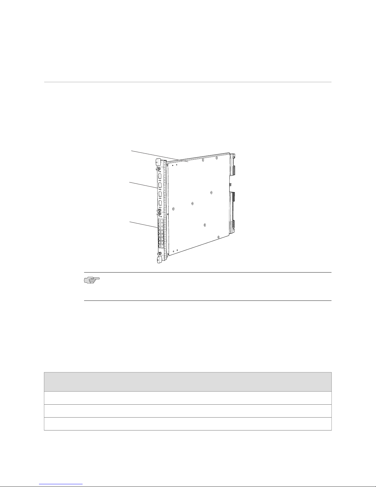
Flex IOC
4x10GE-XFP
port module
in slot 0
16x1GE-TX
port module
in slot 1
SRX 5600 and SRX 5800 Services Gateway Flex IOC and Port Module Installation Instructions
Flex I/O Cards and Port Modules
Flex I/O Cards (flex IOCs) are IOCs with two slots, which accept port modules that
add Ethernet ports to your services gateway. A flex IOC with installed port modules
functions in the same way as a regular IOC, but allows greater flexibility in adding
different types of Ethernet ports to your services gateway. Figure 1 on page 2 shows
a flex IOC with two typical port modules installed.
Figure 1: Flex IOC with Port Modules
NOTE: Your services gateway must be running JUNOS version 9.5R1 or later in order
to recognize flex IOCs and port modules.
Each flex IOC has a processor subsystem, which includes a 1.2-GHz CPU, a system
controller, 1 GB SDRAM, and two Packet Forwarding Engines (PFEs) with a maximum
throughput of 10 Gbps each. See “Installing a Flex IOC” on page 11 and “Removing
a Flex IOC” on page 9 for information about installing and removing flex IOCs.
Table 1 on page 2 describes the different port modules available.
Table 1: Port Module Types
Port TypeNumber of PortsPort Module Name
Maximum
Throughput
Oversubscription
Ratio
4:110 GbpsXFP 10 Gbps44x10GE-XFP
1.6:110 GbpsRJ-45 1 Gbps1616x1GE-TX
1.6:110 GbpsSFP 1 Gbps1616x1GE-SFP
2 ■ Flex I/O Cards and Port Modules
Page 3
g030274
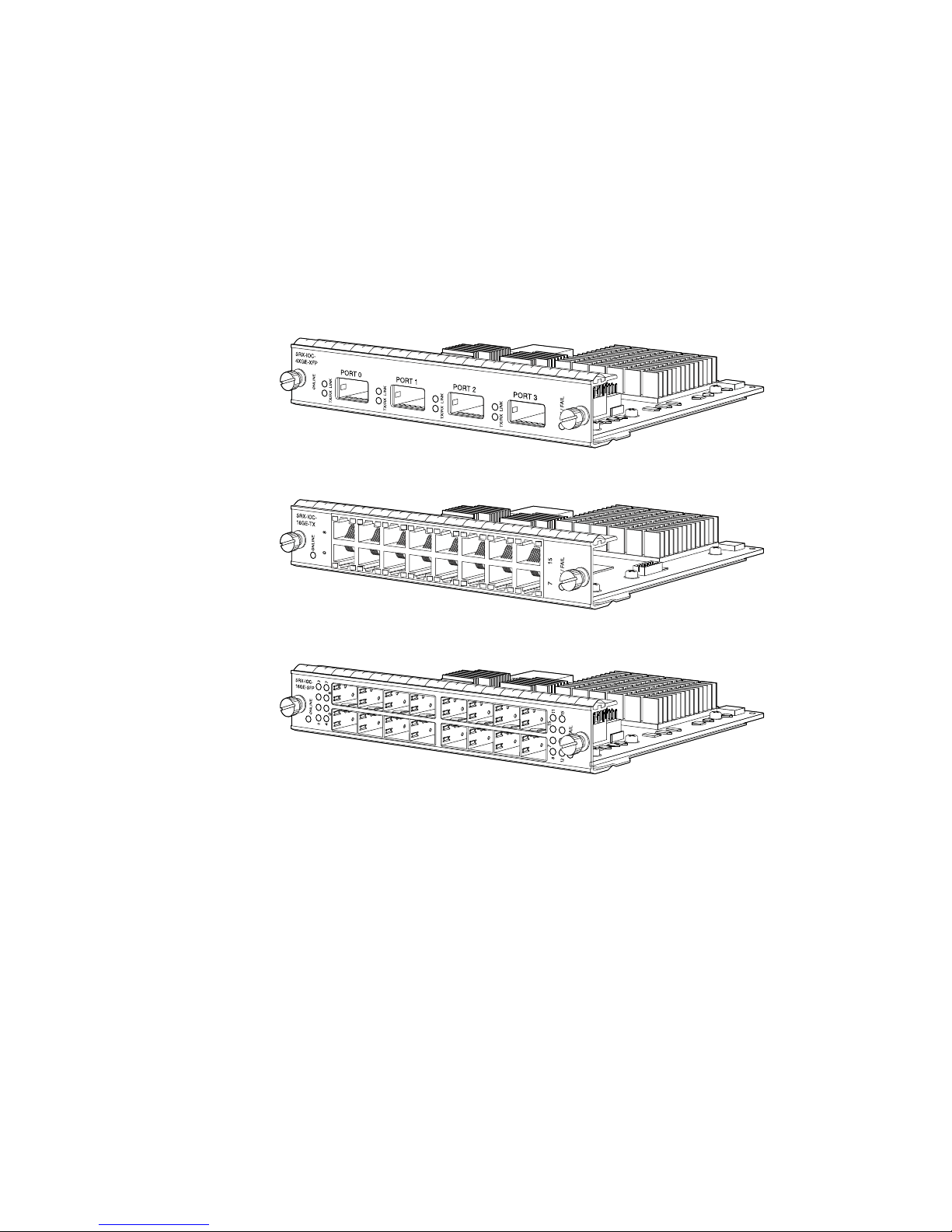
SRX-IOC-16GE-TX 16-Port RJ-45
SRX-IOC-16GE-SFP 16-Port SFP
SRX-IOC-4XGE-XFP 4-Port XFP
Flex I/O Cards and Port Modules
You use port modules and flex IOCs to add different combinations of SFP, XFP, and
TX ports to your services gateway to suit the specific needs of your network. The
available port modules are shown in Figure 2 on page 3. See “Installing a Port
Module” on page 14 and “Removing a Port Module” on page 12 for information
about installing and removing port modules.
Figure 2: Port Modules Supported on the Flex IOC
Flex IOC Components
Each flex IOC consists of the following components:
■ Flex IOC cover, which functions as a ground plane and a stiffener
■ Two slots for port modules
■ Fabric interfaces
■ Two Gigabit Ethernet interfaces that allow control information, route information,
and statistics to be sent between the Routing Engine and the CPU on the flex
IOC
■ Two interfaces from the SCBs that enable the flex IOC to be powered on and
controlled
■ Two 10 Gbps PFEs
Flex I/O Cards and Port Modules ■ 3
Page 4

SRX 5600 and SRX 5800 Services Gateway Flex IOC and Port Module Installation Instructions
■ Midplane connectors and power circuitry
■ Processor subsystem, including a 1.2-GHz CPU, a system controller, and 1 GB
of SDRAM
Port Module Components
Each port module consists of the following components:
■ Port module cover, which functions as a ground plane and a stiffener
■ Physical I/O port connectors
■ Ethernet switch
■
Online button (behind pinhole) for bringing the port module online and offline
■ Port module slot connectors and power circuitry
Port Module LEDs
LEDs on the faceplate of each port module indicate the status of the module and of
each port. Table 2 on page 4, Table 3 on page 4, and Table 4 on page 5 describe
the LEDs on each port module type.
Table 2: 4-Port 10-Gigabit XFP Ethernet Port Module LEDs
DescriptionStateColorLabel
OK/FAIL
LINK
TX/RX
Table 3: 16-Port SFP Ethernet Port Module LEDs
Port module is functioning normally.On steadilyGreen
Port module has failed.On steadilyRed
Link is active.On steadilyGreen
No link.Off
Port is receiving or transmitting data.BlinkingGreen
No activity.Off
DescriptionStateColorLabel
OK/FAIL
Link 0
through 15
4 ■ Flex I/O Cards and Port Modules
Port module is functioning normally.On steadilyGreen
Port module has failed.On steadilyRed
Link is active.On steadilyGreen
No link.Off
Page 5
Table 4: 16-Port TX Ethernet Port Module LEDs
DescriptionStateColorLabel
Handling and Storing Cards
OK/FAIL
left of each
port)
(bottom or
right of
each port)
Handling and Storing Cards
This section explains how to avoid damaging the cards (IOCs, SPCs, host subsystems,
and port modules) that you install into the services gateway. Many components on
the cards are fragile.
CAUTION: Failure to handle cards as specified in this document can cause irreparable
damage.
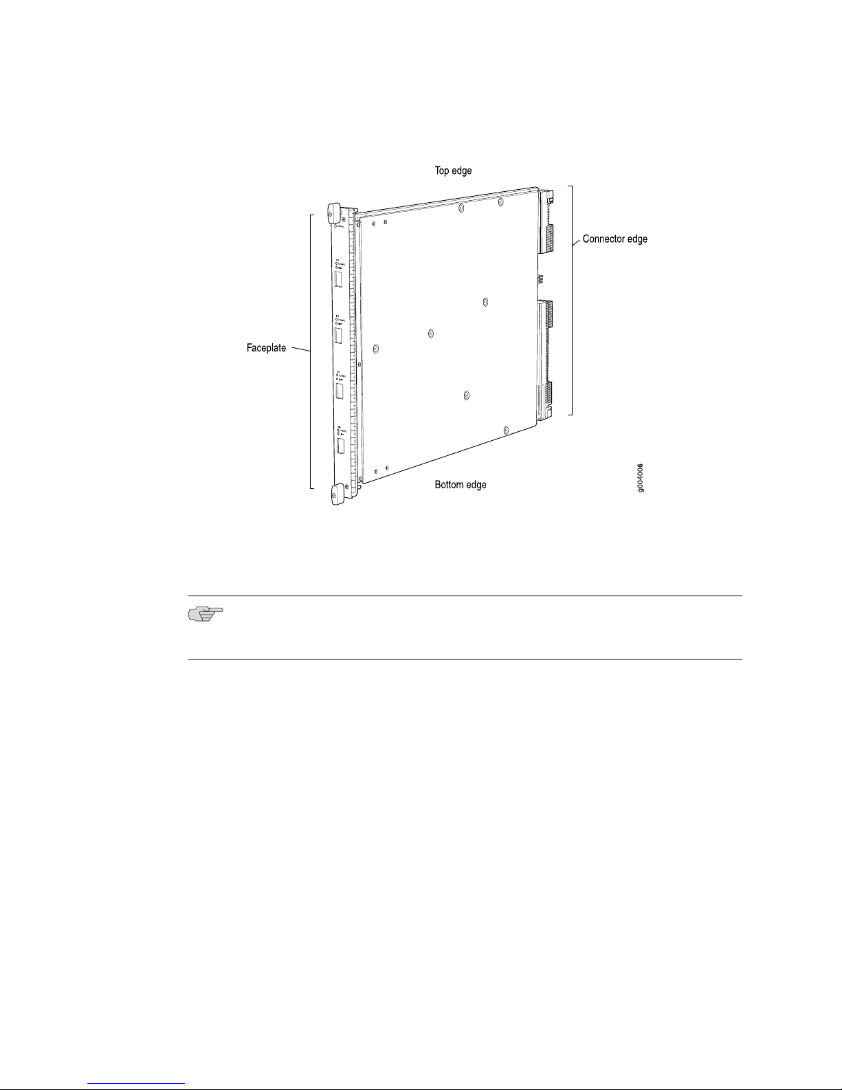
This section discusses how to hold cards in both the vertical and horizontal positions.
Regardless of orientation, this section uses the same terms for all four edges of the
card (see Figure 3 on page 6):
Port module is functioning normally.On steadilyGreen
Port module has failed.On steadilyRed
Link is active.On steadilyGreenLink (top or
No link.Off
Port is receiving or transmitting data.BlinkingGreenTX/RX
No activity.Off
■ Faceplate—Edge of the card that has connectors to which you connect cables or
sockets for SFP or XFP transceivers.
■ Connector edge—Edge opposite the faceplate; this edge has the connectors that
attach to the midplane.
■ Top edge—Edge at the top of the card when it is vertical.
■ Bottom edge—Edge at the bottom of the card when it is vertical.
NOTE: The instructions in this section apply to all card and port module types.
Handling and Storing Cards ■ 5
Page 6
SRX 5600 and SRX 5800 Services Gateway Flex IOC and Port Module Installation Instructions
Figure 3: Card Edges
Holding a Card
When you carry a card, you can hold it either vertically or horizontally.
NOTE: A card weighs up to 13.1 lb (5.9 kg). Be prepared to accept the full weight of
the card as you lift it.
To hold a card vertically:
1. Orient the card so that the faceplate faces you. To verify orientation, confirm
that the text on the card is right-side up and the electromagnetic interference
(EMI) strip is on the right-hand side.
2. Place one hand around the card faceplate about a quarter of the way down from
the top edge. To avoid deforming the EMI shielding strip, do not press hard on
it.
3. Place your other hand at the bottom edge of the card.
If the card is horizontal before you grasp it, place your left hand around the faceplate
and your right hand along the bottom edge.
To hold a card horizontally:
1. Orient the card so that the faceplate faces you.
2. Grasp the top edge with your left hand and the bottom edge with your right hand.
6 ■ Handling and Storing Cards
Page 7

Handling and Storing Cards
You can rest the faceplate of the card against your body as you carry it.
As you carry the card, do not bump it against anything. Card components are fragile.
Never hold or grasp the card anywhere except the places that this document indicates.
In particular, never grasp the connector edge, especially at the power connector in
the corner where the connector and bottom edges meet (see Figure 4 on page 7).
Figure 4: Do Not Grasp the Connector Edge
Handling and Storing Cards ■ 7
Page 8

SRX 5600 and SRX 5800 Services Gateway Flex IOC and Port Module Installation Instructions
Never carry the card by the faceplate with only one hand.
Do not rest any edge of a card directly against a hard surface (see Figure 5 on page
8).
Do not stack cards.
Figure 5: Do Not Rest the Card on an Edge
If you must rest the card temporarily on an edge while changing its orientation
between vertical and horizontal, use your hand as a cushion between the edge and
the surface.
Storing a Card
You must store a card as follows:
■ In the device chassis
■ In the container in which a spare card is shipped
■ Horizontally and sheet metal side down
When you store a card on a horizontal surface or in the shipping container, always
place it inside an antistatic bag. Because the card is heavy, and because antistatic
bags are fragile, inserting the card into the bag is easier with two people. To do this,
one person holds the card in the horizontal position with the faceplate facing the
body, and the other person slides the opening of the bag over the card connector
edge.
8 ■ Handling and Storing Cards
Page 9

If you must insert the card into a bag by yourself, first lay the card horizontally on
a flat, stable surface, sheet metal side down. Orient the card with the faceplate facing
you. Carefully insert the card connector edge into the opening of the bag, and pull
the bag toward you to cover the card.
Never stack a card under or on top of any other component.
Replacing Flex IOCs and Port Modules
You install flex IOCs and port modules in the front of the services gateway. You install
flex IOCs directly in the card cage. You install port modules into flex IOCs. Flex IOCs
and port modules are hot-insertable and hot-removable. When you remove a flex
IOC or port module, the services gateway continues to function, although the flex
IOC or port module being removed no longer functions. Before replacing a flex IOC
or port module, review the information in “Handling and Storing Cards” on page 5.
To replace a flex IOC or port module, use the following procedures:
■ Removing a Flex IOC on page 9
■ Installing a Flex IOC on page 11
■ Removing a Port Module on page 12
■ Installing a Port Module on page 14
Replacing Flex IOCs and Port Modules
Removing a Flex IOC
A flex IOC weighs up to 13.1 lb (5.9 kg). Be prepared to accept the full weight of the
card as you remove it.
To remove a flex IOC (see Figure 6 on page 10):
1. Have ready a replacement card or blank panel and an antistatic mat for the flex
IOC.
2. Attach an electrostatic discharge (ESD) grounding strap to your bare wrist and
connect the strap to one of the ESD points on the chassis. For more information
about ESD, see “Preventing Electrostatic Discharge Damage” on page 16.
3. Use one of the following methods to take the flex IOC offline:
■ Press and hold the corresponding online button on the craft interface. The
green OK LED next to the button begins to blink. Hold the button down until
the LED goes off.
■ Issue the following CLI command:
user@host>request chassis fpc slot slot-number offline
For more information about the command, see the JUNOS System Basics and
Services Command Reference.
4. If you have not already done so, remove the port modules installed in the flex
IOC as described in “Removing a Port Module” on page 12.
Replacing Flex IOCs and Port Modules ■ 9
Page 10

Flex IOC
g030277
SRX 5600 and SRX 5800 Services Gateway Flex IOC and Port Module Installation Instructions
5. Simultaneously turn both of the ejector handles counterclockwise to unseat the
flex IOC.
6. Grasp the handles and slide the flex IOC straight out of the card cage halfway.
7. Place one hand around the front of the flex IOC and the other hand under it to
support it. Slide the flex IOC completely out of the chassis, and place it on the
antistatic mat or in the electrostatic bag.
CAUTION: The weight of the flex IOC is concentrated in the back end. Be prepared
to accept the full weight—up to 13.1 lb (5.9 kg)—as you slide the flex IOC out of the
chassis.
When the flex IOC is out of the chassis, do not hold it by the ejector handles, bus
bars, or edge connectors. They cannot support its weight.
Do not stack flex IOCs on top of one another after removal. Place each one individually
in an electrostatic bag or on its own antistatic mat on a flat, stable surface.
8. If you are not reinstalling a replacement card into the empty slot within a short
time, install a blank panel over the slot to maintain proper airflow in the card
cage.
CAUTION: After removing an IOC from the chassis, wait at least 30 seconds before
reinserting it, removing an IOC from a different slot, or inserting an IOC into a
different slot.
Figure 6: Removing a Flex IOC
10 ■ Replacing Flex IOCs and Port Modules
Page 11

Installing a Flex IOC
Flex IOC
g030276
Replacing Flex IOCs and Port Modules
NOTE: Your services gateway must be running JUNOS version 9.5R1 or later in order
to recognize flex IOCs and port modules.
To install a flex IOC (see Figure 7 on page 11):
1. Attach an electrostatic discharge (ESD) grounding strap to your bare wrist and
connect the strap to one of the ESD points on the chassis. For more information
about ESD, see “Preventing Electrostatic Discharge Damage” on page 16.
2. Place the flex IOC on an antistatic mat or remove it from its electrostatic bag.
3. Identify the slot on the services gateway where you will install the flex IOC.
4. If you have not already done so, remove the blank panel from the slot where
you are installing the flex IOC.
5. Orient the flex IOC so that the faceplate faces you.
6. Lift the flex IOC into place and carefully align the sides of the card with the guides
inside the card cage.
7. Slide the flex IOC all the way into the card cage until you feel resistance.
Figure 7: Installing a Flex IOC
8. Grasp both ejector handles and rotate them clockwise simultaneously until the
flex IOC is fully seated.
9. Use one of the following methods to bring the flex IOC online:
■ Press and hold the corresponding online button on the craft interface until
■ Issue the following CLI command:
the green OK LED next to the button lights steadily, in about 5 seconds.
user@host>request chassis fpc slot slot-number online
Replacing Flex IOCs and Port Modules ■ 11
Page 12

SRX 5600 and SRX 5800 Services Gateway Flex IOC and Port Module Installation Instructions
For more information about the command, see the JUNOS System Basics and
Services Command Reference.
CAUTION: After the OK LED turns green, wait at least 30 seconds before removing
the IOC again, removing an IOC from a different slot, or inserting an IOC in a different
slot.
Removing a Port Module
Port modules are installed in flex IOCs in the services gateway card cage. A port
module weighs up to 3 lb (1.4 kg). Be prepared to accept its full weight when you
remove or install a port module.
To remove a port module (see Figure 8 on page 13):
1. Have ready a replacement port module or blank panel and an antistatic mat for
the port module. Also have ready rubber safety caps for each port on the port
module you are removing that uses an optical interface.
2. Attach an electrostatic discharge (ESD) grounding strap to your bare wrist and
connect the strap to one of the ESD points on the chassis. For more information
about ESD, see “Preventing Electrostatic Discharge Damage” on page 16.
3. Label the cables connected to each port on the port module so that you can later
reconnect the cables to the correct ports.
4. Use one of the following methods to take the port module offline:
■
Insert a pointed tool into the ONLINE pinhole on the front panel of the port
module to press the button behind it. Hold the button down until the OK/FAIL
LED goes off.
■ Issue the following CLI command:
user@host>request chassis fpc-slot slot-number pic-slot slot-number offline
For more information about the command, see the JUNOS System Basics and
Services Command Reference.
5. Disconnect the cables from the port module. If the port module uses fiber-optic
cable, immediately cover each transceiver and the end of each cable with a
rubber safety cap. Arrange the disconnected cables in the cable management
system to prevent the cables from developing stress points.
WARNING: Do not look directly into a fiber-optic transceiver or into the ends of
fiber-optic cables. Fiber-optic transceivers and fiber-optic cable connected to a
transceiver emit laser light that can damage your eyes.
12 ■ Replacing Flex IOCs and Port Modules
Page 13

g030273
Replacing Flex IOCs and Port Modules
CAUTION: Do not leave a fiber-optic transceiver uncovered except when inserting
or removing cable. The safety cap keeps the port clean and prevents accidental
exposure to laser light.
CAUTION: Avoid bending fiber-optic cable beyond its minimum bend radius. An arc
smaller than a few inches in diameter can damage the cable and cause problems
that are difficult to diagnose.
6. Loosen the captive screws that retain the port module in its slot in the flex IOC.
7. Grasp the captive screws and slide the port module straight out of the flex IOC
halfway.
8. Place one hand around the front of the port module and the other hand under
it to support it. Slide the port module completely out of the flex IOC, and place
it on the antistatic mat or in the electrostatic bag.
Figure 8: Removing a Port Module
9. If you are not reinstalling a port module into the empty slot within a short time,
install a blank panel over the slot to maintain proper airflow in the card cage.
CAUTION: After removing a port module from the chassis, wait at least 30 seconds
before reinserting it, removing a port module from a different slot, or inserting a
port module into a different slot.
Replacing Flex IOCs and Port Modules ■ 13
Page 14

g030272
SRX 5600 and SRX 5800 Services Gateway Flex IOC and Port Module Installation Instructions
Installing a Port Module
To install a port module (see Figure 9 on page 14):
1. Attach an electrostatic discharge (ESD) grounding strap to your bare wrist and
connect the strap to one of the ESD points on the chassis. For more information
about ESD, see “Preventing Electrostatic Discharge Damage” on page 16.
2. If you have not already done so, install the flex IOC in which you are installing
the port module, as described in “Installing a Flex IOC” on page 11.
3. Place the port module on an antistatic mat or remove it from its electrostatic
bag.
4. Verify that each fiber-optic transceiver is covered with a rubber safety cap. If it
is not, cover the transceiver with a safety cap.
5. If necessary, remove the blank panel covering the slot in the flex IOC where you
are installing the port module.
6. Orient the port module so that the faceplate faces you.
7. Lift the port module into place and carefully align the sides of the port module
with the guides inside the flex IOC.
8. Slide the port module all the way into the flex IOC until it is fully seated.
9. Tighten both captive screws to secure the port module in the flex IOC.
Figure 9: Installing a Port Module
10. If the port module uses fiber-optic interfaces, remove the rubber safety cap from
each transceiver and cable.
WARNING: Do not look directly into a fiber-optic transceiver or into the ends of
fiber-optic cables. Fiber-optic transceivers and fiber-optic cable connected to a
transceiver emit laser light that can damage your eyes.
14 ■ Replacing Flex IOCs and Port Modules
Page 15

Replacing Flex IOCs and Port Modules
11. Insert the appropriate cables into the cable connector ports on each port module.
Secure the cables so that they are not supporting their own weight. Place excess
cable out of the way in a neatly coiled loop, using the cable management system.
Placing fasteners on a loop helps to maintain its shape.
CAUTION: Do not let fiber-optic cable hang free from the connector. Do not allow
fastened loops of cable to dangle, which stresses the cable at the fastening point.
CAUTION: Avoid bending fiber-optic cable beyond its minimum bend radius. An arc
smaller than a few inches in diameter can damage the cable and cause problems
that are difficult to diagnose.
12. Use one of the following methods to take the port module online:
■
Insert a pointed tool into the ONLINE pinhole on the front panel of the port
module to press the button behind it. Hold the button down until the OK/FAIL
LED at the opposite end of the front panel lights green steadily, in about
5 seconds.
■ Issue the following CLI command:
user@host>request chassis fpc-slot slot-number pic-slot slot-number online
For more information about the command, see the JUNOS System Basics and
Services Command Reference.
CAUTION: After the OK/FAIL LED turns green, wait at least 30 seconds before
removing the port module again, removing a port module from a different slot, or
inserting a port module in a different slot.
You can also verify that the port module is functioning correctly by issuing the
show chassis fpc and show chassis fpc pic-status commands, as described in the
JUNOS System Basics and Services Command Reference.
Replacing Flex IOCs and Port Modules ■ 15
Page 16

SRX 5600 and SRX 5800 Services Gateway Flex IOC and Port Module Installation Instructions
Preventing Electrostatic Discharge Damage
Many services gateway hardware components are sensitive to damage from static
electricity. Some components can be impaired by voltages as low as 30 V. You can
easily generate potentially damaging static voltages whenever you handle plastic or
foam packing material or if you move components across plastic or carpets. Observe
the following guidelines to minimize the potential for electrostatic discharge (ESD)
damage, which can cause intermittent or complete component failures:
■ Always use an ESD wrist strap or ankle strap, and verify that it is in direct contact
with your skin.
CAUTION: For safety, periodically check the resistance value of the ESD strap. The
measurement should be in the range of 1 to 10 Mohms.
■ When handling any component that has been removed from the chassis, verify
that the equipment end of your ESD strap is attached to one of the ESD points
on the chassis, which are shown in Figure 11 on page 17 and Figure 12 on page
18.
■ Avoid contact between the component and your clothing. ESD voltages emitted
from clothing can still damage components.
■ When removing or installing a component, always place it component-side up
on an antistatic surface, in an antistatic card rack, or into an electrostatic bag
(see Figure 10 on page 16). If you are returning a component, place it into an
electrostatic bag before packing it.
Figure 10: Placing a Component into an Electrostatic Bag
Electrostatic Discharge Point
Figure 11 on page 17 and Figure 12 on page 18 show the location of the ESD point
on the front of each chassis.
16 ■ Preventing Electrostatic Discharge Damage
Page 17

Electrostatic Discharge Point
Figure 11: Front View of a Fully Configured SRX 5600 Services Gateway Chassis
Electrostatic Discharge Point ■ 17
Page 18

SRX 5600 and SRX 5800 Services Gateway Flex IOC and Port Module Installation Instructions
Figure 12: Front View of a Fully Configured SRX 5800 Services Gateway Chassis
18 ■ Electrostatic Discharge Point
Page 19

List of Technical Publications
Table 5 on page 19 lists the hardware guides and release notes for Juniper Networks
SRX–series services gateways and describes the contents of each document. All
documents are available at http://www.juniper.net/techpubs/.
Table 5: Technical Documentation for Supported Devices
DescriptionBook
Hardware Documentation
SRX 5600 Services Gateway Hardware Guide or
SRX 5800 Services Gateway Hardware Guide
Release Notes
JUNOS Software for SRX-series Services Gateway
Release Notes
Describes how to install, maintain, and troubleshoot the services
gateway and components. Each services gateway type has its own
hardware guide.
Summarizes new features and known problems for a particular
release of JUNOS software on SRX-series services gateways,
including J-Web interface features and problems. The release notes
also contain corrections and updates to the manuals and software
upgrade and downgrade.
List of Technical Publications
Requesting Technical Support
Technical product support is available through the Juniper Networks Technical
Assistance Center (JTAC). If you are a customer with an active J-Care or JNASC support
contract, or are covered under warranty, and need postsales technical support, you
can access our tools and resources online or open a case with JTAC.
■ JTAC policies—For a complete understanding of our JTAC procedures and policies,
review the JTAC User Guide located at
http://www.juniper.net/customers/support/downloads/710059.pdf.
■ Product warranties—For product warranty information, visit
http://www.juniper.net/support/warranty/.
■ JTAC Hours of Operation —The JTAC centers have resources available 24 hours
a day, 7 days a week, 365 days a year.
Self-Help Online Tools and Resources
For quick and easy problem resolution, Juniper Networks has designed an online
self-service portal called the Customer Support Center (CSC) that provides you with
the following features:
■
Find CSC offerings: http://www.juniper.net/customers/support/
■
Search for known bugs: http://www2.juniper.net/kb/
■
Find product documentation: http://www.juniper.net/techpubs/
■ Find solutions and answer questions using our Knowledge Base:
http://kb.juniper.net/
List of Technical Publications ■ 19
Page 20

SRX 5600 and SRX 5800 Services Gateway Flex IOC and Port Module Installation Instructions
■ Download the latest versions of software and review release notes:
http://www.juniper.net/customers/csc/software/
■ Search technical bulletins for relevant hardware and software notifications:
https://www.juniper.net/alerts/
■ Join and participate in the Juniper Networks Community Forum:
http://www.juniper.net/company/communities/
■
Open a case online in the CSC Case Management tool: http://www.juniper.net/cm/
To verify service entitlement by product serial number, use our Serial Number
Entitlement (SNE) Tool located at https://tools.juniper.net/SerialNumberEntitlementSearch/.
Opening a Case with JTAC
You can open a case with JTAC on the Web or by telephone.
■
Use the Case Management tool in the CSC at http://www.juniper.net/cm/ .
■ Call 1-888-314-JTAC (1-888-314-5822 toll-free in the USA, Canada, and Mexico).
For international or direct-dial options in countries without toll-free numbers, visit
us at http://www.juniper.net/support/requesting-support.html.
Revision History
April 2009—530-029503-01. Revision 01 Initial release.
May 2009—530-029503-01. Revision 02 Add note requiring JUNOS 9.5R1 or later.
Copyright © 2009, Juniper Networks, Inc. All rights reserved.
Juniper Networks, the Juniper Networks logo, JUNOS, NetScreen, ScreenOS, and Steel-Belted Radius are registered trademarks of Juniper Networks, Inc. in
the United States and other countries. JUNOSe is a trademark of Juniper Networks, Inc. All other trademarks, service marks, registered trademarks, or
registered service marks are the property of their respective owners.
Juniper Networks assumes no responsibility for any inaccuracies in this document. Juniper Networks reserves the right to change, modify, transfer, or
otherwise revise this publication without notice.
Products made or sold by Juniper Networks or components thereof might be covered by one or more of the following patents that are owned by or licensed
to Juniper Networks: U.S. Patent Nos. 5,473,599, 5,905,725, 5,909,440, 6,192,051, 6,333,650, 6,359,479, 6,406,312, 6,429,706, 6,459,579, 6,493,347,
6,538,518, 6,538,899, 6,552,918, 6,567,902, 6,578,186, and 6,590,785.
20 ■ Requesting Technical Support
 Loading...