

Page 1

Juniper Secure Analytics 3800 Hardware Guide
Published: 2015-03-16
Copyright © 2015, Juniper Networks, Inc.
Page 2

Juniper Networks, Inc.
1133 Innovation Way
Sunnyvale, California 94089
USA
408-745-2000
www.juniper.net
Copyright © 2015, Juniper Networks, Inc. All rights reserved.
Juniper Networks, Junos, Steel-Belted Radius, NetScreen, and ScreenOS are registered trademarks of Juniper Networks, Inc. in the United
States and other countries. The Juniper Networks Logo, the Junos logo, and JunosE are trademarks of Juniper Networks, Inc. All other
trademarks, service marks, registered trademarks, or registered service marks are the property of their respective owners.
Juniper Networks assumes no responsibility for any inaccuracies in this document. Juniper Networks reserves the right to change, modify,
transfer, or otherwise revise this publication without notice.
Juniper Secure Analytics 3800 Hardware Guide
Copyright © 2015, Juniper Networks, Inc.
All rights reserved.
The information in this document is current as of the date on the title page.
YEAR 2000 NOTICE
Juniper Networks hardware and software products are Year 2000 compliant. Junos OS has no known time-related limitations through the
year 2038. However, the NTP application is known to have some difficulty in the year 2036.
END USER LICENSE AGREEMENT
The Juniper Networks product that is the subject of this technical documentation consists of (or is intended for use with) Juniper Networks
software. Use of such software is subject to the terms and conditions of the End User License Agreement (“EULA”) posted at
http://www.juniper.net/support/eula.html. By downloading, installing or using such software, you agree to the terms and conditions of
that EULA.
Copyright © 2015, Juniper Networks, Inc.ii
Page 3

Table of Contents
About the Documentation . . . . . . . . . . . . . . . . . . . . . . . . . . . . . . . . . . . . . . . . . . . . xi
Documentation and Release Notes . . . . . . . . . . . . . . . . . . . . . . . . . . . . . . . . . . xi
Documentation Conventions . . . . . . . . . . . . . . . . . . . . . . . . . . . . . . . . . . . . . . . xi
Documentation Feedback . . . . . . . . . . . . . . . . . . . . . . . . . . . . . . . . . . . . . . . . xiii
Requesting Technical Support . . . . . . . . . . . . . . . . . . . . . . . . . . . . . . . . . . . . . xiv
Self-Help Online Tools and Resources . . . . . . . . . . . . . . . . . . . . . . . . . . . xiv
Opening a Case with JTAC . . . . . . . . . . . . . . . . . . . . . . . . . . . . . . . . . . . . . xiv
Part 1 Overview
Chapter 1 System Overview . . . . . . . . . . . . . . . . . . . . . . . . . . . . . . . . . . . . . . . . . . . . . . . . . . . 3
JSA3800 Appliance Description . . . . . . . . . . . . . . . . . . . . . . . . . . . . . . . . . . . . . . . . 3
JSA3800 Appliance Hardware Overview . . . . . . . . . . . . . . . . . . . . . . . . . . . . . . . . . 4
Chapter 2 Hardware Component Overview . . . . . . . . . . . . . . . . . . . . . . . . . . . . . . . . . . . . . 5
JSA3800 Appliance Components Overview . . . . . . . . . . . . . . . . . . . . . . . . . . . . . . . 5
Chapter 3 Chassis Description . . . . . . . . . . . . . . . . . . . . . . . . . . . . . . . . . . . . . . . . . . . . . . . . . 7
JSA3800 Appliance Front Panel Description . . . . . . . . . . . . . . . . . . . . . . . . . . . . . . 7
JSA3800 Appliance Back Panel Description . . . . . . . . . . . . . . . . . . . . . . . . . . . . . . 9
Part 2 Site Planning and Specifications
Chapter 4 Planning and Preparing the Site . . . . . . . . . . . . . . . . . . . . . . . . . . . . . . . . . . . . . 15
General Site Installation Guidelines for the JSA3800 Appliance . . . . . . . . . . . . . . 15
JSA3800 Appliance Physical Specifications . . . . . . . . . . . . . . . . . . . . . . . . . . . . . . 15
JSA3800 Appliance Rack Requirements . . . . . . . . . . . . . . . . . . . . . . . . . . . . . . . . . 17
Additional Hardware Requirements . . . . . . . . . . . . . . . . . . . . . . . . . . . . . . . . . . . . . 17
Chapter 5 Network Transceiver Specifications . . . . . . . . . . . . . . . . . . . . . . . . . . . . . . . . . . 19
JSA3800 Appliance Transceiver Interface . . . . . . . . . . . . . . . . . . . . . . . . . . . . . . . . 19
Part 3 Initial Installation and Configuration
Chapter 6 Installation Overview . . . . . . . . . . . . . . . . . . . . . . . . . . . . . . . . . . . . . . . . . . . . . . 23
Overview of Installing the JSA3800 Appliance in a Rack . . . . . . . . . . . . . . . . . . . . 23
Tools and Parts Required for Installing the JSA3800 Appliance . . . . . . . . . . . . . . 23
Chapter 7 Installing the JSA3800 Appliance . . . . . . . . . . . . . . . . . . . . . . . . . . . . . . . . . . . 25
Installing the JSA3800 Appliance . . . . . . . . . . . . . . . . . . . . . . . . . . . . . . . . . . . . . . 25
Installing the JSA3800 Appliance Using Front-and-Rear-Mounting Flush in a
Four-Post Rack . . . . . . . . . . . . . . . . . . . . . . . . . . . . . . . . . . . . . . . . . . . . . . . . . 27
Mid-Mounting the JSA3800 Appliance in a Two-Post Rack . . . . . . . . . . . . . . . . . 29
iiiCopyright © 2015, Juniper Networks, Inc.
Page 4

Juniper Secure Analytics 3800 Hardware Guide
Chapter 8 Grounding the JSA3800 Appliance . . . . . . . . . . . . . . . . . . . . . . . . . . . . . . . . . . 33
Grounding the JSA3800 Appliance . . . . . . . . . . . . . . . . . . . . . . . . . . . . . . . . . . . . . 33
Chapter 9 Connecting the JSA3800 Appliance to External Devices . . . . . . . . . . . . . . . 35
Connecting the JSA3800 Appliance to a Management Device . . . . . . . . . . . . . . . 35
Chapter 10 Providing Power to the JSA3800 Appliance . . . . . . . . . . . . . . . . . . . . . . . . . . 37
Connecting the JSA3800 Appliance to a DC Power Source . . . . . . . . . . . . . . . . . . 37
Chapter 11 Performing the Initial Configuration . . . . . . . . . . . . . . . . . . . . . . . . . . . . . . . . . 39
Preparing the Network Hierarchy . . . . . . . . . . . . . . . . . . . . . . . . . . . . . . . . . . . . . . 39
Identifying Network Settings . . . . . . . . . . . . . . . . . . . . . . . . . . . . . . . . . . . . . . 40
Identifying Security Monitoring Devices and Flow Data Sources . . . . . . . . . . 40
Identifying Network Assets . . . . . . . . . . . . . . . . . . . . . . . . . . . . . . . . . . . . . . . . 41
Configuring the Basic Settings on the JSA3800 Appliance . . . . . . . . . . . . . . . . . . 42
Accessing the JSA Interface . . . . . . . . . . . . . . . . . . . . . . . . . . . . . . . . . . . . . . . . . . . 43
Part 4 Maintaining and Troubleshooting Components
Chapter 12 Maintaining Components . . . . . . . . . . . . . . . . . . . . . . . . . . . . . . . . . . . . . . . . . . 47
Maintaining the JSA3800 RAID Array . . . . . . . . . . . . . . . . . . . . . . . . . . . . . . . . . . . 47
Maintaining the JSA3800 Power Supply . . . . . . . . . . . . . . . . . . . . . . . . . . . . . . . . 48
Chapter 13 Troubleshooting Components . . . . . . . . . . . . . . . . . . . . . . . . . . . . . . . . . . . . . . 49
Contacting Juniper Networks Technical Assistance Center . . . . . . . . . . . . . . . . . . 49
Part 5 Replacing Components
Chapter 14 Overview of Replacing Components . . . . . . . . . . . . . . . . . . . . . . . . . . . . . . . . . 53
Field-Replaceable Units on the JSA3800 Appliance . . . . . . . . . . . . . . . . . . . . . . . 53
Chapter 15 Replacing Power System Components . . . . . . . . . . . . . . . . . . . . . . . . . . . . . . . 55
Replacing an AC Power Supply on the JSA3800 Appliance . . . . . . . . . . . . . . . . . 55
Replacing AC Power Supply Cables on the JSA3800 Appliance . . . . . . . . . . . . . . 56
Replacing a DC Power Supply on the JSA3800 Appliance . . . . . . . . . . . . . . . . . . 56
Replacing DC Power Supply Cables on the JSA3800 Appliance . . . . . . . . . . . . . . 57
Part 6 Safety and Regulatory Compliance Information
Chapter 16 General Safety Guidelines and Warnings . . . . . . . . . . . . . . . . . . . . . . . . . . . . . 61
Definitions of Safety Warning Levels . . . . . . . . . . . . . . . . . . . . . . . . . . . . . . . . . . . . 61
General Safety Guidelines and Warnings . . . . . . . . . . . . . . . . . . . . . . . . . . . . . . . . 63
Qualified Personnel Warning . . . . . . . . . . . . . . . . . . . . . . . . . . . . . . . . . . . . . . . . . . 64
Warning Statement for Norway and Sweden . . . . . . . . . . . . . . . . . . . . . . . . . . . . . 65
Prevention of Electrostatic Discharge Damage . . . . . . . . . . . . . . . . . . . . . . . . . . . 65
Chapter 17 Fire Safety Requirements . . . . . . . . . . . . . . . . . . . . . . . . . . . . . . . . . . . . . . . . . . 67
Fire Safety Requirements . . . . . . . . . . . . . . . . . . . . . . . . . . . . . . . . . . . . . . . . . . . . . 67
Chapter 18 Installation Safety Guidelines and Warnings . . . . . . . . . . . . . . . . . . . . . . . . . 69
Installation Instructions Warning . . . . . . . . . . . . . . . . . . . . . . . . . . . . . . . . . . . . . . 69
Chassis Lifting Guidelines for the JSA3800 Appliance . . . . . . . . . . . . . . . . . . . . . . 70
Copyright © 2015, Juniper Networks, Inc.iv
Page 5

Table of Contents
Ramp Warning . . . . . . . . . . . . . . . . . . . . . . . . . . . . . . . . . . . . . . . . . . . . . . . . . . . . . 70
Rack-Mounting Warnings . . . . . . . . . . . . . . . . . . . . . . . . . . . . . . . . . . . . . . . . . . . . . 71
Grounded Equipment Warning . . . . . . . . . . . . . . . . . . . . . . . . . . . . . . . . . . . . . . . . 75
Chapter 19 Laser and LED Safety Guidelines and Warnings . . . . . . . . . . . . . . . . . . . . . . . 77
Laser and LED Safety Guidelines and Warnings for JSA . . . . . . . . . . . . . . . . . . . . . 77
General Laser Safety Guidelines . . . . . . . . . . . . . . . . . . . . . . . . . . . . . . . . . . . . 77
Class 1 Laser Product Warning . . . . . . . . . . . . . . . . . . . . . . . . . . . . . . . . . . . . . 78
Class 1 LED Product Warning . . . . . . . . . . . . . . . . . . . . . . . . . . . . . . . . . . . . . . 78
Laser Beam Warning . . . . . . . . . . . . . . . . . . . . . . . . . . . . . . . . . . . . . . . . . . . . . 79
Radiation from Open Port Apertures Warning . . . . . . . . . . . . . . . . . . . . . . . . . . . . 80
Chapter 20 Maintenance and Operational Safety Guidelines and Warnings . . . . . . . . . 83
Maintenance and Operational Safety Guidelines and Warnings . . . . . . . . . . . . . . 83
Battery Handling Warning . . . . . . . . . . . . . . . . . . . . . . . . . . . . . . . . . . . . . . . . 83
Jewelry Removal Warning . . . . . . . . . . . . . . . . . . . . . . . . . . . . . . . . . . . . . . . . 84
Lightning Activity Warning . . . . . . . . . . . . . . . . . . . . . . . . . . . . . . . . . . . . . . . . 85
Operating Temperature Warning . . . . . . . . . . . . . . . . . . . . . . . . . . . . . . . . . . . 86
Product Disposal Warning . . . . . . . . . . . . . . . . . . . . . . . . . . . . . . . . . . . . . . . . 87
Chapter 21 Electrical Safety Guidelines and Warnings . . . . . . . . . . . . . . . . . . . . . . . . . . . 89
Action to Take After an Electrical Accident . . . . . . . . . . . . . . . . . . . . . . . . . . . . . . . 89
General Electrical Safety Guidelines and Warnings . . . . . . . . . . . . . . . . . . . . . . . . 90
AC Power Electrical Safety Guidelines . . . . . . . . . . . . . . . . . . . . . . . . . . . . . . . . . . . 91
AC Power Disconnection Warning . . . . . . . . . . . . . . . . . . . . . . . . . . . . . . . . . . . . . . 92
DC Power Electrical Safety Guidelines . . . . . . . . . . . . . . . . . . . . . . . . . . . . . . . . . . 93
DC Power Disconnection Warning . . . . . . . . . . . . . . . . . . . . . . . . . . . . . . . . . . . . . 94
DC Power Grounding Requirements and Warning . . . . . . . . . . . . . . . . . . . . . . . . . 96
DC Power Wiring Sequence Warning . . . . . . . . . . . . . . . . . . . . . . . . . . . . . . . . . . . . 97
DC Power Wiring Terminations Warning . . . . . . . . . . . . . . . . . . . . . . . . . . . . . . . . . 98
Multiple Power Supplies Disconnection Warning . . . . . . . . . . . . . . . . . . . . . . . . . 100
TN Power Warning . . . . . . . . . . . . . . . . . . . . . . . . . . . . . . . . . . . . . . . . . . . . . . . . . 100
Chapter 22 Agency Approvals and Regulatory Compliance Information . . . . . . . . . . . 103
Agency Approvals for the JSA3800 Appliance . . . . . . . . . . . . . . . . . . . . . . . . . . . 103
Compliance Statements for EMC Requirements for the JSA3800 Appliance . . . 104
Canada . . . . . . . . . . . . . . . . . . . . . . . . . . . . . . . . . . . . . . . . . . . . . . . . . . . . . . 104
European Community . . . . . . . . . . . . . . . . . . . . . . . . . . . . . . . . . . . . . . . . . . . 105
Japan . . . . . . . . . . . . . . . . . . . . . . . . . . . . . . . . . . . . . . . . . . . . . . . . . . . . . . . . 105
Korea . . . . . . . . . . . . . . . . . . . . . . . . . . . . . . . . . . . . . . . . . . . . . . . . . . . . . . . . 105
United States . . . . . . . . . . . . . . . . . . . . . . . . . . . . . . . . . . . . . . . . . . . . . . . . . . 105
FCC Part 15 Statement . . . . . . . . . . . . . . . . . . . . . . . . . . . . . . . . . . . . . . . . . . 105
Compliance Statements for Acoustic Noise for the JSA3800 Appliance . . . . . . 106
Part 7 Index
Index . . . . . . . . . . . . . . . . . . . . . . . . . . . . . . . . . . . . . . . . . . . . . . . . . . . . . . . . 109
vCopyright © 2015, Juniper Networks, Inc.
Page 6

Juniper Secure Analytics 3800 Hardware Guide
Copyright © 2015, Juniper Networks, Inc.vi
Page 7

List of Figures
Part 1 Overview
Chapter 3 Chassis Description . . . . . . . . . . . . . . . . . . . . . . . . . . . . . . . . . . . . . . . . . . . . . . . . . 7
Figure 1: JSA3800 Front Panel . . . . . . . . . . . . . . . . . . . . . . . . . . . . . . . . . . . . . . . . . . 7
Figure 2: JSA3800 Front Panel LEDs . . . . . . . . . . . . . . . . . . . . . . . . . . . . . . . . . . . . . 8
Figure 3: JSA3800 Back Panel . . . . . . . . . . . . . . . . . . . . . . . . . . . . . . . . . . . . . . . . . . 9
Figure 4: JSA3800 Ethernet Port LEDs . . . . . . . . . . . . . . . . . . . . . . . . . . . . . . . . . . 10
Part 3 Initial Installation and Configuration
Chapter 7 Installing the JSA3800 Appliance . . . . . . . . . . . . . . . . . . . . . . . . . . . . . . . . . . . 25
Figure 5: Connecting the AC Power Cord . . . . . . . . . . . . . . . . . . . . . . . . . . . . . . . . . 25
Figure 6: JSA3800 Front Panel LEDs . . . . . . . . . . . . . . . . . . . . . . . . . . . . . . . . . . . . 26
Figure 7: Attaching the Inner Rail Extension . . . . . . . . . . . . . . . . . . . . . . . . . . . . . . . 27
Figure 8: Installing the Outer Rails in a Rack . . . . . . . . . . . . . . . . . . . . . . . . . . . . . . 28
Figure 9: Aligning the Chassis in a Rack . . . . . . . . . . . . . . . . . . . . . . . . . . . . . . . . . 28
Figure 10: Installing the JSA3800 Appliance Front-Rear Mounting Flush in a
Four-Post Rack . . . . . . . . . . . . . . . . . . . . . . . . . . . . . . . . . . . . . . . . . . . . . . . . . 29
Figure 11: Securing the Brackets to the Rack . . . . . . . . . . . . . . . . . . . . . . . . . . . . . . 30
Figure 12: Mounting the Outer Rails to the Rack . . . . . . . . . . . . . . . . . . . . . . . . . . . . 31
Figure 13: Securing Brackets to the Outer Rail . . . . . . . . . . . . . . . . . . . . . . . . . . . . . 31
Figure 14: Attaching the Inner Rail Extension . . . . . . . . . . . . . . . . . . . . . . . . . . . . . . 32
Figure 15: Aligning and Installing the Chassis in a Two-Post Rack . . . . . . . . . . . . . 32
Chapter 9 Connecting the JSA3800 Appliance to External Devices . . . . . . . . . . . . . . . 35
Figure 16: Connecting the Management Device . . . . . . . . . . . . . . . . . . . . . . . . . . . 35
Part 6 Safety and Regulatory Compliance Information
Chapter 16 General Safety Guidelines and Warnings . . . . . . . . . . . . . . . . . . . . . . . . . . . . . 61
Figure 17: Placing a Component into an Antistatic Bag . . . . . . . . . . . . . . . . . . . . . 66
viiCopyright © 2015, Juniper Networks, Inc.
Page 8

Juniper Secure Analytics 3800 Hardware Guide
Copyright © 2015, Juniper Networks, Inc.viii
Page 9

List of Tables
About the Documentation . . . . . . . . . . . . . . . . . . . . . . . . . . . . . . . . . . . . . . . . . . xi
Table 1: Notice Icons . . . . . . . . . . . . . . . . . . . . . . . . . . . . . . . . . . . . . . . . . . . . . . . . . xii
Table 2: Text and Syntax Conventions . . . . . . . . . . . . . . . . . . . . . . . . . . . . . . . . . . . xii
Part 1 Overview
Chapter 3 Chassis Description . . . . . . . . . . . . . . . . . . . . . . . . . . . . . . . . . . . . . . . . . . . . . . . . . 7
Table 3: JSA3800 Front Panel Components . . . . . . . . . . . . . . . . . . . . . . . . . . . . . . . 7
Table 4: JSA3800 Front Panel LEDs . . . . . . . . . . . . . . . . . . . . . . . . . . . . . . . . . . . . . 9
Table 5: JSA3800 Back Panel Components . . . . . . . . . . . . . . . . . . . . . . . . . . . . . . 10
Table 6: JSA3800 Ethernet Port LEDs . . . . . . . . . . . . . . . . . . . . . . . . . . . . . . . . . . . 10
Part 2 Site Planning and Specifications
Chapter 4 Planning and Preparing the Site . . . . . . . . . . . . . . . . . . . . . . . . . . . . . . . . . . . . . 15
Table 7: JSA3800 Appliance Physical Specifications . . . . . . . . . . . . . . . . . . . . . . . 16
Table 8: Rack Requirements for JSA3800 . . . . . . . . . . . . . . . . . . . . . . . . . . . . . . . . 17
Table 9: Required JSA Ports . . . . . . . . . . . . . . . . . . . . . . . . . . . . . . . . . . . . . . . . . . . 18
Chapter 5 Network Transceiver Specifications . . . . . . . . . . . . . . . . . . . . . . . . . . . . . . . . . . 19
Table 10: JSA3800 Appliance Transceiver Interface Types . . . . . . . . . . . . . . . . . . . 19
Part 3 Initial Installation and Configuration
Chapter 6 Installation Overview . . . . . . . . . . . . . . . . . . . . . . . . . . . . . . . . . . . . . . . . . . . . . . 23
Table 11: Required Tools and Parts for Installing the JSA3800 Appliance . . . . . . . 23
Chapter 7 Installing the JSA3800 Appliance . . . . . . . . . . . . . . . . . . . . . . . . . . . . . . . . . . . 25
Table 12: DB-9 Console Connector Pinouts for the JSA3800 Appliance . . . . . . . . 26
Chapter 11 Performing the Initial Configuration . . . . . . . . . . . . . . . . . . . . . . . . . . . . . . . . . 39
Table 13: Network Hierarchy . . . . . . . . . . . . . . . . . . . . . . . . . . . . . . . . . . . . . . . . . . . 39
Table 14: Asset Identification . . . . . . . . . . . . . . . . . . . . . . . . . . . . . . . . . . . . . . . . . . 41
ixCopyright © 2015, Juniper Networks, Inc.
Page 10

Juniper Secure Analytics 3800 Hardware Guide
Copyright © 2015, Juniper Networks, Inc.x
Page 11

About the Documentation
•
Documentation and Release Notes on page xi
•
Documentation Conventions on page xi
•
Documentation Feedback on page xiii
•
Requesting Technical Support on page xiv
Documentation and Release Notes
To obtain the most current version of all Juniper Networks®technical documentation,
see the product documentation page on the Juniper Networks website at
http://www.juniper.net/techpubs/.
If the information in the latest release notes differs from the information in the
documentation, follow the product Release Notes.
Juniper Networks Books publishes books by Juniper Networks engineers and subject
matter experts. These books go beyond the technical documentation to explore the
nuances of network architecture, deployment, and administration. The current list can
be viewed at http://www.juniper.net/books.
Documentation Conventions
Table 1 on page xii defines notice icons used in this guide.
xiCopyright © 2015, Juniper Networks, Inc.
Page 12

Juniper Secure Analytics 3800 Hardware Guide
Table 1: Notice Icons
DescriptionMeaningIcon
Indicates important features or instructions.Informational note
Indicates a situation that might result in loss of data or hardware damage.Caution
Alerts you to the risk of personal injury or death.Warning
Alerts you to the risk of personal injury from a laser.Laser warning
Indicates helpful information.Tip
Table 2 on page xii defines the text and syntax conventions used in this guide.
Table 2: Text and Syntax Conventions
Represents text that you type.Bold text like this
Fixed-width text like this
Italic text like this
Italic text like this
Represents output that appears on the
terminal screen.
•
Introduces or emphasizes important
new terms.
•
Identifies guide names.
•
Identifies RFC and Internet draft titles.
Represents variables (options for which
you substitute a value) in commands or
configuration statements.
Alerts you to a recommended use or implementation.Best practice
ExamplesDescriptionConvention
To enter configuration mode, type the
configure command:
user@host> configure
user@host> show chassis alarms
No alarms currently active
•
A policy term is a named structure
that defines match conditions and
actions.
•
Junos OS CLI User Guide
•
RFC 1997, BGP CommunitiesAttribute
Configure the machine’s domain name:
[edit]
root@# set system domain-name
domain-name
Copyright © 2015, Juniper Networks, Inc.xii
Page 13

Table 2: Text and Syntax Conventions (continued)
Text like this
Represents names of configuration
statements, commands, files, and
directories;configurationhierarchylevels;
or labels on routing platform
components.
About the Documentation
ExamplesDescriptionConvention
•
To configure a stub area, include the
stub statement at the [edit protocols
ospf area area-id] hierarchy level.
•
The console port islabeledCONSOLE.
stub <default-metric metric>;Encloses optionalkeywords orvariables.< > (angle brackets)
| (pipe symbol)
# (pound sign)
[ ] (square brackets)
Indention and braces ( { } )
; (semicolon)
GUI Conventions
Bold text like this
Indicatesa choice betweenthe mutually
exclusivekeywordsor variables oneither
side of the symbol. The set of choices is
often enclosed in parentheses forclarity.
same lineas theconfiguration statement
to which it applies.
Encloses a variable for which you can
substitute one or more values.
Identifies a level in the configuration
hierarchy.
Identifies a leaf statement at a
configuration hierarchy level.
Representsgraphicaluser interface (GUI)
items you click or select.
broadcast | multicast
(string1 | string2 | string3)
rsvp { # Required for dynamic MPLS onlyIndicates a comment specified on the
community name members [
community-ids ]
[edit]
routing-options {
static {
route default{
nexthop address;
retain;
}
}
}
•
In the Logical Interfaces box, select
All Interfaces.
•
To cancel the configuration, click
Cancel.
> (bold right angle bracket)
Documentation Feedback
We encourage you to provide feedback, comments, and suggestions so that we can
improve the documentation. You can provide feedback by using either of the following
methods:
•
Online feedback rating system—On any page at the Juniper Networks Technical
Documentation site at http://www.juniper.net/techpubs/index.html, simply click the
stars to rate the content, and usethe pop-upform toprovide uswith information about
your experience. Alternately, you can use the online feedback form at
https://www.juniper.net/cgi-bin/docbugreport/.
Separates levels in a hierarchy of menu
selections.
In the configuration editor hierarchy,
select Protocols>Ospf.
xiiiCopyright © 2015, Juniper Networks, Inc.
Page 14

Juniper Secure Analytics 3800 Hardware Guide
•
E-mail—Sendyour comments totechpubs-comments@juniper.net.Includethe document
or topic name, URL or page number, and software version (if applicable).
Requesting Technical Support
Technical productsupport isavailablethrough theJuniper Networks Technical Assistance
Center (JTAC). If you are a customer with an active J-Care or JNASC support contract,
or are covered under warranty, and need post-sales technical support, you can access
our tools and resources online or open a case with JTAC.
•
JTAC policies—For a complete understanding of our JTAC procedures and policies,
review the JTAC User Guide located at
http://www.juniper.net/us/en/local/pdf/resource-guides/7100059-en.pdf.
•
Product warranties—For product warranty information, visit
http://www.juniper.net/support/warranty/.
•
JTAC hours of operation—The JTAC centers have resources available 24 hours a day,
7 days a week, 365 days a year.
Self-Help Online Tools and Resources
For quick and easy problem resolution, Juniper Networks has designed an online
self-service portal called the Customer SupportCenter (CSC)that provides you with the
following features:
•
Find CSC offerings: http://www.juniper.net/customers/support/
•
Search for known bugs: http://www2.juniper.net/kb/
•
Find product documentation: http://www.juniper.net/techpubs/
•
Find solutions and answer questions using our Knowledge Base: http://kb.juniper.net/
•
Download the latest versions of software and review release notes:
http://www.juniper.net/customers/csc/software/
•
Search technical bulletins for relevant hardware and software notifications:
http://kb.juniper.net/InfoCenter/
•
Join and participate in the Juniper Networks Community Forum:
http://www.juniper.net/company/communities/
•
Open a case online in the CSC Case Management tool: http://www.juniper.net/cm/
To verifyservice entitlement byproduct serial number,use our SerialNumber Entitlement
(SNE) Tool: https://tools.juniper.net/SerialNumberEntitlementSearch/
Opening a Case with JTAC
You can open a case with JTAC on the Web or by telephone.
•
Use the Case Management tool in the CSC at http://www.juniper.net/cm/.
•
Call 1-888-314-JTAC (1-888-314-5822 toll-free in the USA, Canada, and Mexico).
Copyright © 2015, Juniper Networks, Inc.xiv
Page 15

About the Documentation
For international or direct-dial options in countries without toll-free numbers, see
http://www.juniper.net/support/requesting-support.html.
xvCopyright © 2015, Juniper Networks, Inc.
Page 16

Juniper Secure Analytics 3800 Hardware Guide
Copyright © 2015, Juniper Networks, Inc.xvi
Page 17

PART 1
Overview
•
System Overview on page 3
•
Hardware Component Overview on page 5
•
Chassis Description on page 7
1Copyright © 2015, Juniper Networks, Inc.
Page 18

Juniper Secure Analytics 3800 Hardware Guide
Copyright © 2015, Juniper Networks, Inc.2
Page 19

CHAPTER 1
System Overview
•
JSA3800 Appliance Description on page 3
•
JSA3800 Appliance Hardware Overview on page 4
JSA3800 Appliance Description
The Juniper Secure Analytics 3800 (JSA3800) is an enterprise-class appliance that
providesa scalable networksecuritymanagement solution for medium-sizedcompanies
up to large global organizations.
The JSA3800 appliance is a 1-U, rack-mountable chassis with AC power supplies (or
optional DC power supplies), six hot-swappable hard drives, 64 GBmemory, and two10
Gigabit and four Gigabit Ethernet interfaces.
The JSA3800 appliance:
•
Responds to the right threats at the right time through effective analysis of networks,
events, and audit log files.
Related
Documentation
•
Identifies environmental anomalies in the network, an attack path, and the source of
a threat.
•
Provides network remediation for threat responses across all security products.
The JSA appliances use the following drivers for security analysis of external and internal
threats:
•
Security Information Management (SIM)—SIMprovides reportingand analysis ofdata
from host systems, applications, and security devices to support security policy
compliance management, internal threat management, and regulatory compliance
initiatives.
•
Security Event Management (SEM)—SEM improves security incident response
capabilities by processing data from security devices and network devices. It helps
network administrators to provide effective responses toexternal and internal threats.
JSA3800 Appliance Hardware Overview on page 4•
• JSA3800 Appliance Front Panel Description on page 7
• JSA3800 Appliance Back Panel Description on page 9
3Copyright © 2015, Juniper Networks, Inc.
Page 20

Juniper Secure Analytics 3800 Hardware Guide
JSA3800 Appliance Hardware Overview
The JSA3800 appliance provides the following features:
•
Monitor utility for power supply unit (PSU) and fans
•
Add setup logs automatically
•
Support high availability (HA)
•
Hot-swappable hard disk supporting RAID
•
Automatic RAID rebuild on HDD swap
•
Support hot-swappabledual-AC (or optional dual-DCpowersupplies) witha redundant
configuration in the chassis
Related
Documentation
• JSA3800 Appliance Description on page 3
• JSA3800 Appliance Front Panel Description on page 7
• JSA3800 Appliance Back Panel Description on page 9
• General Safety Guidelines and Warnings on page 63
Copyright © 2015, Juniper Networks, Inc.4
Page 21

CHAPTER 2
Hardware Component Overview
•
JSA3800 Appliance Components Overview on page 5
JSA3800 Appliance Components Overview
Juniper Secure Analytics (JSA) includes the following deployment components:
•
Flow Processor—Collects data from devices, and various live and recorded feeds, such
as network taps, span/mirror ports, NetFlow, and JSA flow logs. When the data is
collected, theFlow Processor groups related individual packets into a flow. JSAdefines
these flows as a communication session between two pairs of unique IP addresses
and ports that use the same protocol. A flow starts when the Flow Processor detects
the first packet with a unique source IP address, destination IP address, source port,
destination port, and other specific protocol options that determine the start of a
communication. Each additional packet is evaluated. Counts of bytes and packets are
added to the statistical counters in the flow record. At the end of an interval, a status
record of the flow is sent to an Event Collector, and statistical counters for the flow
are reset. A flow ends when no activity for the flow is detected within the configured
period of time.
Flow reporting generates records of all active or expired flows during a specified period
of time. If the protocol does not support port-based connections, JSA combines all
packets between the two hosts into a single flow record. However, a Flow Processor
does not record flows until a connection is made to another JSA component and data
is retrieved.
•
Event Collector—Collects security events from varioustypes of security devices, known
as log sources, in your network. The Event Collector gathers events from local and
remote log sources. The Event Collector then normalizes the events and sends the
information to the Event Processor. The Event Collector also bundles all virtually
identical events to conserve system usage.
•
Event Processor—An Event Processor processes event and flow data from the Event
Collector. The events are bundled to conserve network usage. When received, the
EventProcessor correlates the informationfrom JSA anddistributes itto theappropriate
area, depending on the type of event. The Event Processor also includes information
gathered by JSA to indicate any behavioral changes or policy violations for that event.
Rulesare thenapplied tothe eventsthat allow the Event Processor to processaccording
to the configured rules. When complete, the Event Processor sends the events to the
Magistrate.
5Copyright © 2015, Juniper Networks, Inc.
Page 22

Juniper Secure Analytics 3800 Hardware Guide
A non-consoleEvent Processorcan beconnected to the Event Processor on theconsole
or connected to another Event Processor in your deployment. The Accumulator is
responsible for gathering flow and event information from the Event Processor.
The Event Processor on the console is always connected to the Magistrate. This
connection cannot be deleted.
•
Off-site Source—Indicatesan offsite event or flow data source thatforwardsnormalized
data to an Event Collector. You can configure an offsite source to receive flows or
events and allow the data to be encrypted before forwarding.
•
Off-site Target—Indicates an offsite device that receives event or flow data. An offsite
target can only receive data from an Event Collector.
•
Magistrate—The Magistrate component provides the core processing components of
the security information and event management (SIEM) system. You can add one
Magistrate component for each deployment. The Magistrate provides views, reports,
alerts, and analysis of network traffic and security events. The Magistrate processes
the eventsor flows against the defined custom rules to createan offense. If no custom
rules exist, the Magistrate uses the default rule set to process the offending event or
flow. An offense is an event or a flow that has been processed through JSA using
multipleinputs, individualevents orflows,and combinedevents or flowswith analyzed
behavior and vulnerabilities. The Magistrate prioritizes the offenses and assigns a
magnitude value based on several factors, including the amount of offenses, severity,
relevance, and credibility.
Related
Documentation
• Preparing the Network Hierarchy on page 39
• JSA3800 Appliance Description on page 3
• General Safety Guidelines and Warnings on page 63
Copyright © 2015, Juniper Networks, Inc.6
Page 23
CHAPTER 3
Chassis Description
•
JSA3800 Appliance Front Panel Description on page 7
•
JSA3800 Appliance Back Panel Description on page 9
JSA3800 Appliance Front Panel Description
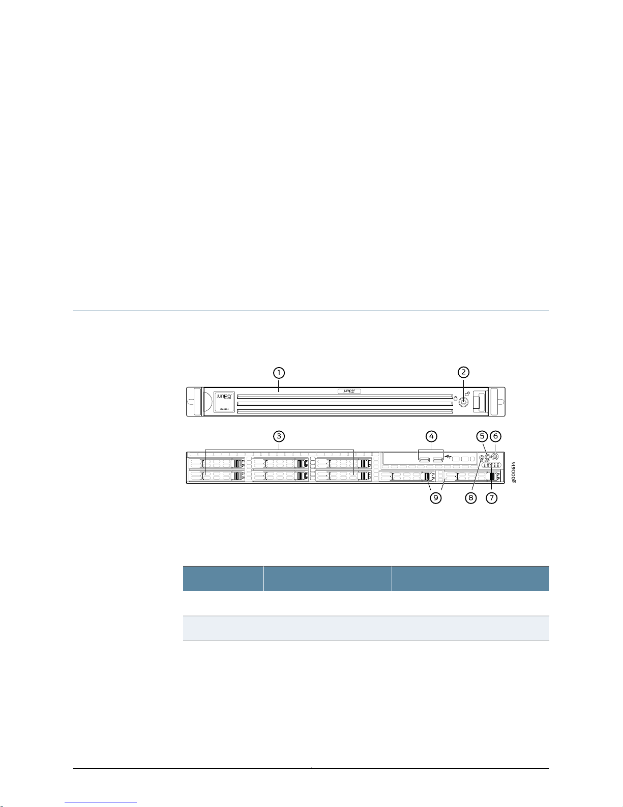
Figure 1 on page 7 shows the front panel components of the JSA3800 appliance.
Figure 1: JSA3800 Front Panel
Table 3 on page 7 provides information about the front panel components of the
JSA3800 appliance.
Table 3: JSA3800 Front Panel Components
DescriptionComponentCallout
Protects the appliance.Front bezel1
Locks the appliance.Lock2
7Copyright © 2015, Juniper Networks, Inc.
Page 24
Juniper Secure Analytics 3800 Hardware Guide
Table 3: JSA3800 Front Panel Components (continued)
DescriptionComponentCallout
Hard drive3
USB ports4
Chassis LEDs7
UID button8
Six 900 GB hard disk drives (Drive0 Derive 5).
•
Drive1 (top left) and Drive0 (bottom
left)
•
Drive3 (top middle) and Drive2
(bottom middle)
•
Drive5 (top right) andDrive4 (bottom
right)
2 USB ports that accept a USB storage
device.
Reboots the appliance.RESET button5
Powers on or powers off the appliance.Power button6
Provides the colors and states, and the
status they indicate.
Turns on or off the blue light function of
the U-LED when used with a
UID-compatiblemotherboard. Oncethe
blue light is activated, you can easily
locate the appliance in very large racks
and server banks.
Empty hard drive slots.Empty slots9
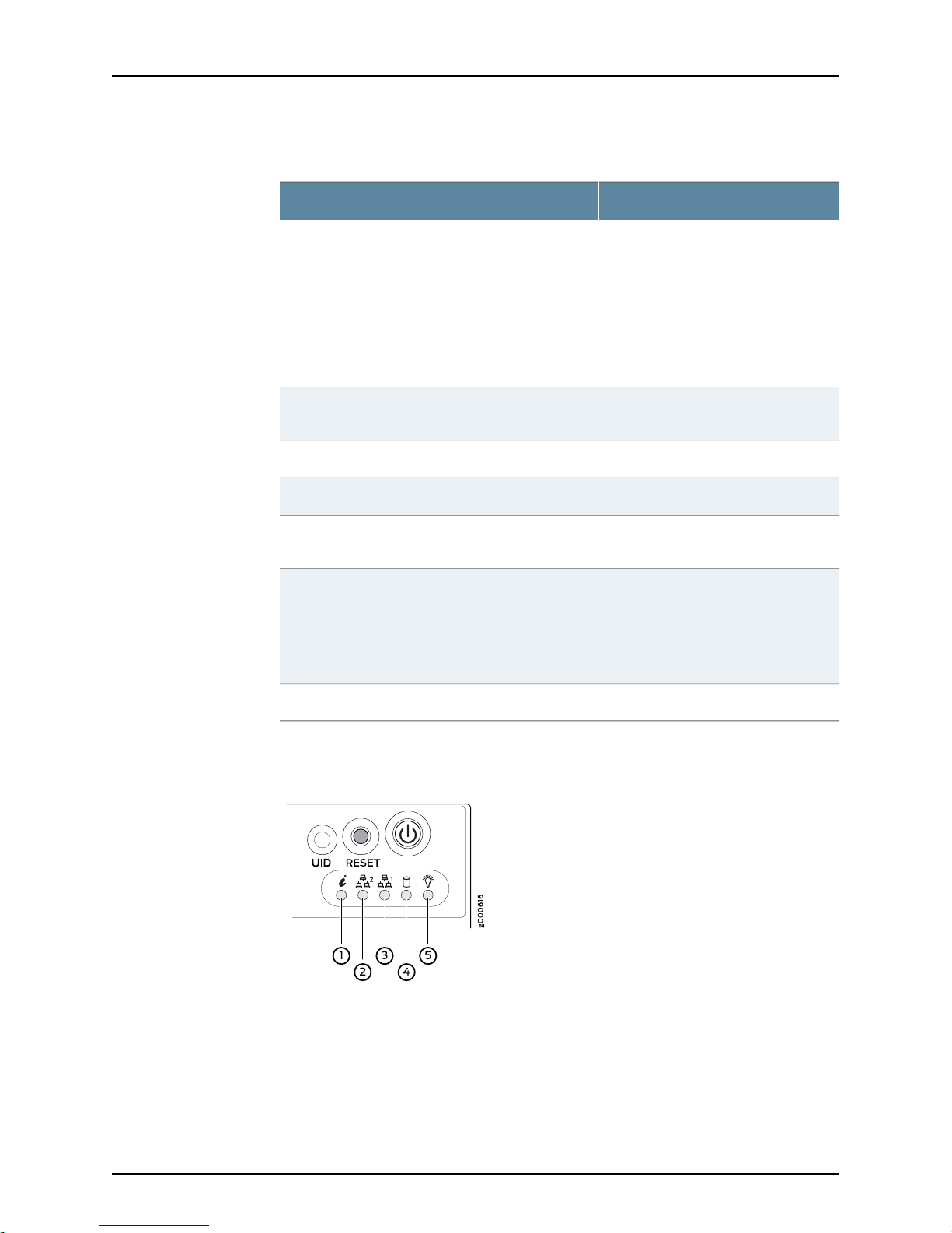
Figure 2 on page 8 shows the front panel LEDs of the JSA3800 appliance.
Figure 2: JSA3800 Front Panel LEDs
Table 4 on page 9 lists the JSA3800 front panel LEDs.
Copyright © 2015, Juniper Networks, Inc.8
Page 25
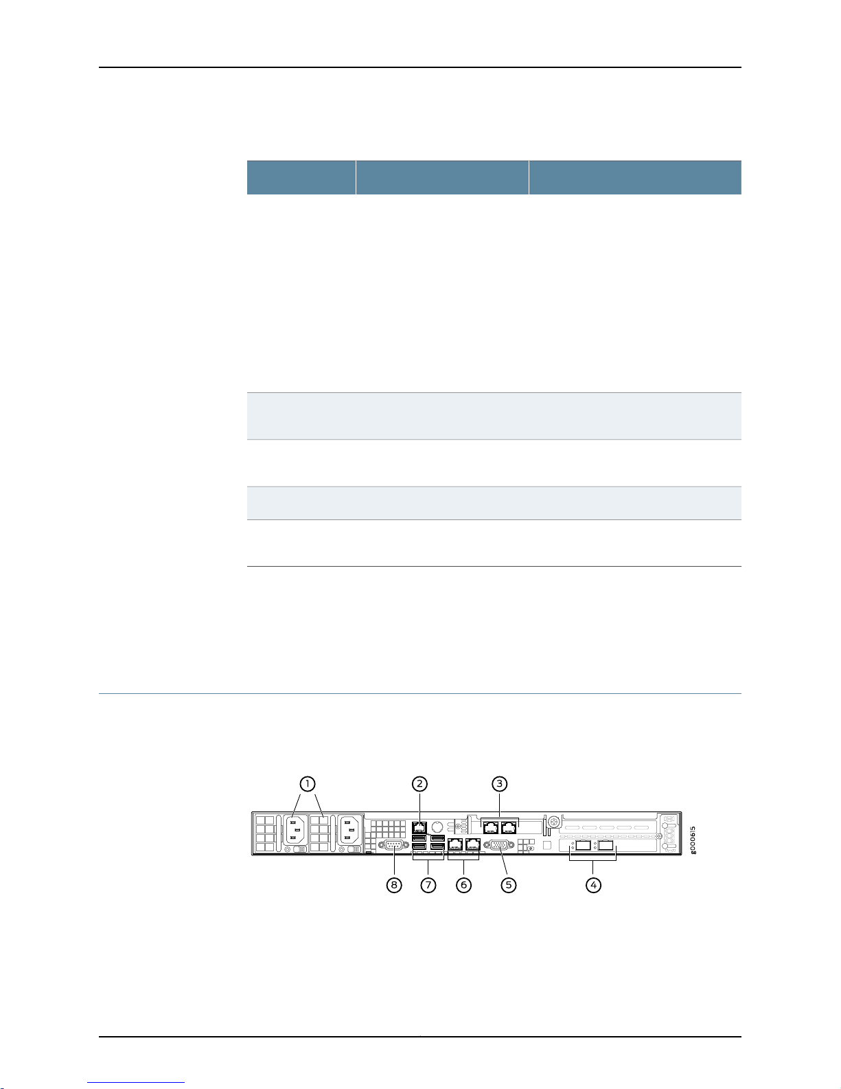
Table 4: JSA3800 Front Panel LEDs
Information1
Chapter 3: Chassis Description
DescriptionLEDsCallout
•
Red(blinking)—Indicatesa fanfailure.
•
Solid red—Indicates an overheat
condition, which might be caused by
cables obstructing the airflow in the
system or the ambient room
temperature being too warm.
•
Red (slowly blinking)—Indicates a
power failure.
•
Solid Blue—Indicates that the local
UID button is depressed.
•
Blue (blinking)—Indicates
IPMI-activated UID.
LAN22
LAN13
Power5
Related
Documentation
JSA3800 Appliance Description on page 3•
• JSA3800 Appliance Hardware Overview on page 4
• JSA3800 Appliance Back Panel Description on page 9
JSA3800 Appliance Back Panel Description
Figure 3 on page 9 shows the back panel components of the JSA3800 appliance.
Figure 3: JSA3800 Back Panel
When blinking, it indicates DataShare
interface activity.
When blinking,it indicatesManagement
interface activity.
Unused.Hard drive4
Solid green—Indicatesthat the appliance
is receiving power.
Table 5 on page 10 provides information about the back panel components of the
JSA3800 appliance.
9Copyright © 2015, Juniper Networks, Inc.
Page 26
Juniper Secure Analytics 3800 Hardware Guide
Table 5: JSA3800 Back Panel Components
DescriptionComponentsCallout
Provides power to all components.Power supply1
1 dedicated IPMI LAN port.Dedicated IPMI LAN port2
GB ports3
VGA port5
GB ports6
2 RJ-45 Gigabit Ethernet LAN ports. The left Ethernet
port is Eth0 and the right Ethernet port is Eth1.
NOTE: You can choose any GB ports as the
management port.
2 SFP+ 10GbE LAN ports.10 GB+SFP ports4
1 VGA port.
NOTE: This port is not supported.
2 RJ-45 Gigabit Ethernet LAN ports.
NOTE: You can choose any GB ports as the
management port.
4 USB ports.USB ports7
1 DB-9 COM port.COM port8
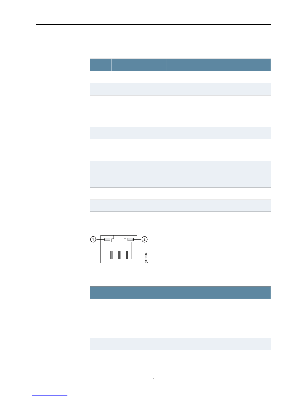
Figure 4 on page 10 shows the back panel Ethernet port LEDs of theJSA3800 appliance.
Figure 4: JSA3800 Ethernet Port LEDs
Table 6 on page 10 lists the JSA3800 Ethernet port LEDs.
Table 6: JSA3800 Ethernet Port LEDs
DescriptionLEDsCallout
•
Link1
Off—Indicates no connection or the
speed of the connection is 10 Mbps.
•
Green—Indicates that the speed of
the connection is 100 Mbps.
•
Amber—Indicates that the speed of
the connection is 1 Gbps.
Indicates link activity.Activity2
Copyright © 2015, Juniper Networks, Inc.10
Page 27

Chapter 3: Chassis Description
Related
Documentation
• JSA3800 Appliance Description on page 3
• JSA3800 Appliance Hardware Overview on page 4
• JSA3800 Appliance Front Panel Description on page 7
11Copyright © 2015, Juniper Networks, Inc.
Page 28

Juniper Secure Analytics 3800 Hardware Guide
Copyright © 2015, Juniper Networks, Inc.12
Page 29

PART 2
Site Planning and Specifications
•
Planning and Preparing the Site on page 15
•
Network Transceiver Specifications on page 19
13Copyright © 2015, Juniper Networks, Inc.
Page 30

Juniper Secure Analytics 3800 Hardware Guide
Copyright © 2015, Juniper Networks, Inc.14
Page 31

CHAPTER 4
Planning and Preparing the Site
•
General Site Installation Guidelines for the JSA3800 Appliance on page 15
•
JSA3800 Appliance Physical Specifications on page 15
•
JSA3800 Appliance Rack Requirements on page 17
•
Additional Hardware Requirements on page 17
General Site Installation Guidelines for the JSA3800 Appliance
The following precautions can help you plan an acceptable operating environment for
your JSA3800 appliance and avoid environmentally caused equipment failures:
•
For the cooling system to function properly, the airflow around the chassis must be
unrestricted. Allow sufficient clearance between the front andback of the chassis and
adjacentequipment. Ensurethat thereis adequate circulationin theinstallation location.
•
Followthe electrostatic discharge(ESD) procedures to avoiddamaging the equipment.
Staticdischarge can cause components to fail, either completely or intermittentlyover
time.
Related
Documentation
Additional Hardware Requirements on page 17•
• JSA3800 Appliance Rack Requirements on page 17
• JSA3800 Appliance Physical Specifications on page 15
JSA3800 Appliance Physical Specifications
Table 7 on page 16 lists the specifications for the JSA3800 appliance.
NOTE: Install the appliance only in restricted areas, such as dedicated
equipment rooms and equipment closets,in accordancewith Articles 110–16,
110–17, and 110–18 of the National Electrical Code, ANSI/NFPA 70.
15Copyright © 2015, Juniper Networks, Inc.
Page 32

Juniper Secure Analytics 3800 Hardware Guide
Table 7: JSA3800 Appliance Physical Specifications
JSA3800Specification
437 mm x 43 mm x 597 mm (17.2 in. x 1.7 in. x 23.5 in.)Dimensions (D x W x H)
27.9 lbWeight
1 year HW, 90 days SWWarranty
5 x 5.6cm counter-rotating PWM fansFans
Panel Display
Ports
Power
Environmental specifications
LEDs: Power, Hard Drive Activity, Network Activity, and
Universal Information
Front-and-rear or mid-mountRack mountable
•
2 SFP+ 10GbE LAN ports
•
4 RJ-45 Gigabit Ethernet LAN ports
•
1 RJ-45 Dedicated IPMI LAN port
•
6 USB 2.0 ports total (4 rear, 2 front)
•
1 VGA port
NOTE: This port is not supported.
•
1 DB-9 COM port
650 W redundant AC-DC Power supply
•
AC Input: 85 - 264 V, 47 - 63 Hz
•
DC Output: 3 A @ +5 V standby; 54 A @ 12 V
650 W DC-DC power supply (optional)
•
DC Input: -40 VDC to -72 VDC, 40 A (Max)
•
DC Output: 3 A @ +5 V standby; 53 A @ 12 V
32° F (0° C) to 104° F (40° C)Temperature operating
-40° F (-40° C) to 158° F (70° C)Temperature storage
5% - 90% noncondensingHumidity operating
5% - 95% noncondensingHumidity storage
10,000 ft max.Altitude operating
35,000 ft max.Altitude storage
781 BTU/hourMaximum thermal output
Copyright © 2015, Juniper Networks, Inc.16
Page 33

Chapter 4: Planning and Preparing the Site
Related
Documentation
JSA3800 Appliance Description on page 3•
• JSA3800 Appliance Hardware Overview on page 4
• Additional Hardware Requirements on page 17
JSA3800 Appliance Rack Requirements
The JSA3800 appliance can be installed in a four-post or two-post rack.
Table 8 on page 17 provides the details of requirements for rack size, clearance, airflow,
spacing of mounting brackets andflange holes,and connecting to the building structure.
Table 8: Rack Requirements for JSA3800
SpecificationsRackRequirement
Size
Clearance
A 19in. (48.3 cm)rack as defined inCabinets, Racks, Panels, and Associated
Equipment (document number EIA-310-D) published by the Electronics
Industry Association (http://www.eia.org).
•
The outer edges of the mounting brackets extend the width of either
chassis to 19 in. (48.3 cm).
•
The front of the chassis extends approximately 1.5 in. (3.81 cm) beyond
the mounting ears.
Spacing of
mounting bracket
and flange holes
Connecting to the
building structure
Related
Documentation
Additional Hardware Requirements on page 17•
• JSA3800 Appliance Physical Specifications on page 15
• General Site Installation Guidelines for the JSA3800 Appliance on page 15
Additional Hardware Requirements
Before installing your JSA3800 appliances, ensure that you have access to the following
additional hardware components:
•
The holes within each rack set are spaced at 1-U [1.75 in. (4.5 cm)]. The
device can be mounted in any rack that provides holes or hole patterns
spaced at 1-U [1.75 in. (4.5 cm)] increments. The holes within each rack
set are spaced at 1-U [1.75 in. (4.5 cm)].
•
The device can be mounted in any rack that provides holes or hole
patterns spaced at 1-U [1.75 in. (4.5 cm)] increments.
•
The mounting brackets and front-mount flanges used to attach the
chassis to a rackare designedto fasten toholes spaced at rack distances
of 1-U (3.5 in.).
•
The mounting holes in the mounting brackets provided with the device
are spaced 1.25 in. (3.2 cm) apart (top and bottom mounting hole).
Always secure the rack in which you are installing the JSA3800 appliance
to the structure of the building. If your geographical area is subject to
earthquakes, bolt the rack to the floor. For maximum stability, also secure
the rack to ceiling brackets.
17Copyright © 2015, Juniper Networks, Inc.
Page 34

Juniper Secure Analytics 3800 Hardware Guide
•
A serial console.
•
To make sure that your JSA data is preserved during a power failure, we recommend
that all JSA3800 appliances or systems running JSA software storing data (such as
consoles, Event Processors, or Flow Processors) be equipped with an uninterruptible
power supply (UPS).
We recommend that you install JSA on your LAN to ensure that it can communicate with
your applicable resources,such asauthentication servers, DNS servers, internal webservers
through HTTP/HTTPS, external websites through HTTP/HTTPS (optional), the Juniper
Networks update server through HTTP, network file system (NFS) file servers (optional),
and client/server applications (optional). Table 9 on page 18 lists port information for
the JSA appliance.
Table 9: Required JSA Ports
Depends on
ConfigurationInternetLANDescriptionPortDirection
Related
Documentation
22In
command-line
management
22Out
connection to
newmanaged
device
80
security
updates from
Juniper
Networks
123
synchronization
• JSA3800 Appliance Hardware Overview on page 4
• JSA3800 Appliance Rack Requirements on page 17
• General Site Installation Guidelines for the JSA3800 Appliance on page 15
NoNoYesSSH
NoNoYesWeb interface443
NoYesYesSSH
NoNoYesDNS lookups53
YesYesYesSystem
YesYesYesNTP time
Copyright © 2015, Juniper Networks, Inc.18
Page 35

CHAPTER 5
Network Transceiver Specifications
•
JSA3800 Appliance Transceiver Interface on page 19
JSA3800 Appliance Transceiver Interface
Table 10 on page 19 lists the transceivers supported on the JSA3800 appliance.
Table 10: JSA3800 Appliance Transceiver Interface Types
DescriptionCard ModelTransceiver Type
Dual Rate 10GBASE-LR/1000BASE-LXUNIV-SFPP-DUAL-SRSFP+
Dual Rate 10GBASE-SR/1000BASE-SXUNIV-SFPP-DUAL-LR
Related
Documentation
• JSA3800 Appliance Description on page 3
• JSA3800 Appliance Back Panel Description on page 9
• JSA3800 Appliance Physical Specifications on page 15
19Copyright © 2015, Juniper Networks, Inc.
Page 36

Juniper Secure Analytics 3800 Hardware Guide
Copyright © 2015, Juniper Networks, Inc.20
Page 37

PART 3
Initial Installation and Configuration
•
Installation Overview on page 23
•
Installing the JSA3800 Appliance on page 25
•
Grounding the JSA3800 Appliance on page 33
•
Connecting the JSA3800 Appliance to External Devices on page 35
•
Providing Power to the JSA3800 Appliance on page 37
•
Performing the Initial Configuration on page 39
21Copyright © 2015, Juniper Networks, Inc.
Page 38

Juniper Secure Analytics 3800 Hardware Guide
Copyright © 2015, Juniper Networks, Inc.22
Page 39

CHAPTER 6
Installation Overview
•
Overview of Installing the JSA3800 Appliance in a Rack on page 23
•
Tools and Parts Required for Installing the JSA3800 Appliance on page 23
Overview of Installing the JSA3800 Appliance in a Rack
The rack-mount system is flexible and offers several options for rack-mounting the
hardware. The different options include:
•
Installing theJSA3800Appliance UsingFront-and-Rear-Mounting Flush in aFour-Post
Rack on page 27
•
Mid-Mounting the JSA3800 Appliance in a Two-Post Rack on page 29
Related
Documentation
Tools and Parts Required for Installing the JSA3800 Appliance on page 23•
• Installing the JSA3800 ApplianceUsing Front-and-Rear-Mounting Flush in a Four-Post
Rack on page 27
• Mid-Mounting the JSA3800 Appliance in a Two-Post Rack on page 29
Tools and Parts Required for Installing the JSA3800 Appliance
Table 11 on page 23 lists the tools and equipment required for installing and maintaining
the JSA3800 appliance.
Table 11: Required Tools and Parts for Installing the JSA3800 Appliance
Tools and PartsTask
•
Installing the JSA3800 appliance
Phillips (+) screwdriver, number 1
•
Phillips (+) screwdriver, number 3
•
Tie wrap
ESD grounding wrist strapConnecting the JSA3800 appliance
Phillips (+) screwdriver, number 1Grounding the JSA3800 appliance
23Copyright © 2015, Juniper Networks, Inc.
Page 40

Juniper Secure Analytics 3800 Hardware Guide
Table 11: Required Tools and Parts for Installing the JSA3800
Appliance (continued)
Packing the JSA3800 appliance
Tools and PartsTask
•
Electrostatic bag or antistatic mat, for each
component
•
ESD grounding wrist strap
Related
Documentation
• Overview of Installing the JSA3800 Appliance in a Rack on page 23
• Installing the JSA3800 ApplianceUsing Front-and-Rear-Mounting Flush in a Four-Post
Rack on page 27
• Mid-Mounting the JSA3800 Appliance in a Two-Post Rack on page 29
Copyright © 2015, Juniper Networks, Inc.24
Page 41

CHAPTER 7
Installing the JSA3800 Appliance
•
Installing the JSA3800 Appliance on page 25
•
Installing theJSA3800Appliance UsingFront-and-Rear-Mounting Flush in aFour-Post
Rack on page 27
•
Mid-Mounting the JSA3800 Appliance in a Two-Post Rack on page 29
Installing the JSA3800 Appliance
Place the shipping container on a flat surface and carefully remove the hardware
components.
To install the JSA3800 appliance:
1. Mount the JSA3800 appliance in your server rack using the attached mounting
brackets. See “Installing the JSA3800 Appliance Using Front-and-Rear-Mounting
Flush in a Four-Post Rack” on page 27 and “Mid-Mounting the JSA3800 Appliance in
a Two-Post Rack” on page 29.
2. Plug the power cord into the AC receptacles on the rear panel as shown in
Figure 5 on page 25.
Figure 5: Connecting the AC Power Cord
NOTE: To connect DC power, see “Connecting the JSA3800 Appliance
to a DC Power Source” on page 37.
3. Plug the other end of the power cord into a wall socket.
4. Plug the Ethernet cable into the Ethernet port on the back panel.
25Copyright © 2015, Juniper Networks, Inc.
Page 42

Juniper Secure Analytics 3800 Hardware Guide
When you turn on the power, the internal port uses two LEDs to indicate the LAN
connection status, as shown in Figure 6 on page 26.
Figure 6: JSA3800 Front Panel LEDs
3—LAN1 LED
4—1— Hard drive LEDInformation LED
5—2— Power LEDLAN2 LED
5. Plug an RS-232 (DB-9 F/F) cable into the console port.
Table 12 on page 26 describes the details of the DB-9 console port pinouts for the
JSA3800 appliance.
Table 12: DB-9 Console Connector Pinouts for the JSA3800 Appliance
DescriptionSignalPin
Data Carrier DetectDCD1
Receive DataRxD2
Transmit DataTxD Output3
Data Terminal ReadyDTR Output4
Chassis GroundGND5
Data Set ReadyDSR Input6
Request to SendRTS Output7
Clear to SendCTS Input8
Ring IndicatorRI9
6. Push the Power button on the front panel.
The Power LED below the power button turns on.
Not ConnectedNC10
Copyright © 2015, Juniper Networks, Inc.26
Page 43

Chapter 7: Installing the JSA3800 Appliance
Related
Documentation
Connecting the JSA3800 Appliance to a Management Device on page 35•
• Grounding the JSA3800 Appliance on page 33
• Connecting the JSA3800 Appliance to a DC Power Source on page 37
Installing the JSA3800Appliance Using Front-and-Rear-Mounting Flush in aFour-Post
Rack
The JSA3800 appliance uses this mounting option as its default configuration. The rack
mounting kit includes two rack rail assemblies. Each assembly consists of an inner fixed
chassis rail that is secured to the server chassisand an outer fixed rack railthat is secured
to the rack.
To mount the JSA3800 appliance on a four-post rack:
1. Install the inner rail extensions (optional).
NOTE: The JSA3800 appliance includes a set of inner rails that are
preattached to the chassis. You can attach optional inner rail extensions
to stabilize the chassis within the rack.
a. Place the inner rail extensions on the side of the chassis such that the hooks on
the chassis clip securely into the rail extension holes.
b. Slide the extensions toward the front of the chassis.
c. Secure the rails with screws as shown in Figure 7 on page 27.
Figure 7: Attaching the Inner Rail Extension
2. Install the outer rails:
a. Attach the shorter outer rails to the longer outer rails.
b. Adjust the length of the rails so that they fit snugly into the rack.
c. Secure the rails to the front and rear of the rack using three M5 screws each as
shown in Figure 8 on page 28.
27Copyright © 2015, Juniper Networks, Inc.
Page 44

Juniper Secure Analytics 3800 Hardware Guide
Figure 8: Installing the Outer Rails in a Rack
3. Align the rear of the chassis inner rails with the front of the rack rails as shown in
Figure 9 on page 28.
Figure 9: Aligning the Chassis in a Rack
4. Keeping the pressure even on both sides, slide the chassis rails into the rack rails until
the locking tabs click into position (you might have to depress the locking tabs when
inserting). See Figure 10 on page 29.
Copyright © 2015, Juniper Networks, Inc.28
Page 45

Chapter 7: Installing the JSA3800 Appliance
Figure 10: Installing the JSA3800 Appliance Front-Rear Mounting Flush
in a Four-Post Rack
5. (Optional) Insert and tighten the thumbscrews that secure the front of the server to
the rack.
Related
Documentation
Overview of Installing the JSA3800 Appliance in a Rack on page 23•
• Tools and Parts Required for Installing the JSA3800 Appliance on page 23
• Mid-Mounting the JSA3800 Appliance in a Two-Post Rack on page 29
Mid-Mounting the JSA3800 Appliance in a Two-Post Rack
This option is suitable for a two-post equipment rack. It allows the appliance to be
mid-mounted so that there is even clearance at the front and rear of the rack.
To mount the appliance using this option:
1. Determine how far the server will extend out from the front of the rack. The chassis
should be positioned to balance the weight between the front and back.
2. Secure four brackets to the rack posts at the desired position. Secure two brackets
to the front rack posts and attach two brackets to the rear rack posts as shown in
Figure 11 on page 30.
29Copyright © 2015, Juniper Networks, Inc.
Page 46

Juniper Secure Analytics 3800 Hardware Guide
Figure 11: Securing the Brackets to the Rack
3. Mount the outer rails on therack bysecuring theracks to the brackets usingM5 screws
as shown in Figure 12 on page 31.
Copyright © 2015, Juniper Networks, Inc.30
Page 47

Chapter 7: Installing the JSA3800 Appliance
Figure 12: Mounting the Outer Rails to the Rack
4. Secure an additional bracket to the front of each outer rail using two M5 screws as
shown in Figure 13 on page 31.
Figure 13: Securing Brackets to the Outer Rail
5. Install the inner rails on the chassis.
31Copyright © 2015, Juniper Networks, Inc.
Page 48

Juniper Secure Analytics 3800 Hardware Guide
a. Place the inner rail extensions on the side of the chassis such that the hooks on
the chassis clip securely into the rail extension holes.
b. Slide the extensions toward the front of the chassis.
c. Secure the rails with screws as shown in Figure 14 on page 32.
Figure 14: Attaching the Inner Rail Extension
6. Align the rear of the chassis inner rails with the front of the outer rails as shown in
Figure 15 on page 32.
7. Keeping the pressure even on both sides, slide the chassis rails into the rack rails.
Related
Documentation
8. Insert and tighten the thumbscrews. See Figure 15 on page 32.
Figure 15: Aligning and Installing the Chassis in a Two-Post Rack
• Overview of Installing the JSA3800 Appliance in a Rack on page 23
• Tools and Parts Required for Installing the JSA3800 Appliance on page 23
• Installing the JSA3800 ApplianceUsing Front-and-Rear-Mounting Flush in a Four-Post
Rack on page 27
Copyright © 2015, Juniper Networks, Inc.32
Page 49

CHAPTER 8
Grounding the JSA3800 Appliance
•
Grounding the JSA3800 Appliance on page 33
Grounding the JSA3800 Appliance
To meet safety and electromagnetic interference (EMI) requirements and to ensure
proper operation, youmust adequately groundthe JSA3800 appliance before connecting
it to the power source.
Grounding for the JSA3800 appliance is provided through the power supply ground.
Ensure that you connect the AC power supply module in the appliance to agrounded AC
power outlet by using an AC power cord (with the grounding pin) appropriate for your
geographical location.
Related
Documentation
• Connecting the JSA3800 Appliance to a DC Power Source on page 37
• Installing the JSA3800 Appliance on page 25
• JSA3800 Appliance Back Panel Description on page 9
33Copyright © 2015, Juniper Networks, Inc.
Page 50

Juniper Secure Analytics 3800 Hardware Guide
Copyright © 2015, Juniper Networks, Inc.34
Page 51

CHAPTER 9
Connecting the JSA3800 Appliance to
External Devices
•
Connecting the JSA3800 Appliance to a Management Device on page 35
Connecting the JSA3800 Appliance to a Management Device
You can control the JSA3800 appliance through a connected management device (such
as a laptop).Use theconsole portto connect your laptopas shown inFigure 16on page35.
Figure 16: Connecting the Management Device
For the location of the ports, refer to the JSA3800 Back Panel Components table in
“JSA3800 Appliance Back Panel Description” on page 9.
To connect a management device with the JSA3800 appliance:
1. Connect external devices using the ports on the back panel of the appliance.
2. If you use a laptop, connect the laptop to the DB-9 serial console port on the back
panel.
NOTE: You can choose any GB ports as the management port.
35Copyright © 2015, Juniper Networks, Inc.
Page 52

Juniper Secure Analytics 3800 Hardware Guide
3. Plug an Ethernet cable into the network port on the back panel.
4. Plug a RS-232 (DB-9 F/F) cable into the console port.
5. Select the appropriate COM port to use.
6. Configure the following port settings:
•
Bits per second = 9600
•
Stop bits = 1
•
Data bits = 8
•
Parity = None
NOTE: When using a laptop to connect to the appliance, you must use a
terminal program, such as HyperTerminal, to connect to the appliance.
Related
Documentation
• Grounding the JSA3800 Appliance on page 33
• Connecting the JSA3800 Appliance to a DC Power Source on page 37
• Installing the JSA3800 Appliance on page 25
Copyright © 2015, Juniper Networks, Inc.36
Page 53

CHAPTER 10
Providing Power to the JSA3800
Appliance
•
Connecting the JSA3800 Appliance to a DC Power Source on page 37
Connecting the JSA3800 Appliance to a DC Power Source
Before connecting your JSA3800 appliance to a DC power source:
•
Ensure that you have taken the necessary precautions to prevent ESD damage.
•
Ensure that you have connected the JSA3800 appliance chassis to earth ground.
Required tools and parts:
•
DC power source cables (12-14 AWG) withends ofthe wirestripped ~12mm and twisted
•
Phillips (+) screwdriver, number 1
CAUTION: Before you connect power to the JSA3800 appliance, attach the
ground wire in one of the below configurations to meet the safety
requirements and to ensure proper operation:
•
Both power supply ground terminals
•
One or both of the chassis ground terminal(s) located to the left of the
power supply modules
•
Both power supply ground terminals
You connect DC source power to theJSA3800 appliance by attaching power cablesfrom
the external DC power sources to the terminal studs on the DC power feed faceplates.
WARNING: DC-powered JSA3800 appliances are intended for installation
only in restricted access locations.
37Copyright © 2015, Juniper Networks, Inc.
Page 54

Juniper Secure Analytics 3800 Hardware Guide
WARNING: Before you perform the following procedure, ensure that power
is removed from the DC circuit. To ensure that all power is off, locate the
circuit breaker on the panel board that services the DC circuit, switch the
circuit breaker to the OFF position, and tape the switch handle of the circuit
breaker in the OFF position.
To connect the DC source power to the JSA3800 appliance:
1. Ensure that the input circuit breaker is open so that the voltage across the DC power
source cable leads is 0 V, and so that the cable leads will not become active while
you are connecting DC power.
2. Connect the stripped and twisted wires to the wire clamps under the DC terminal
screws on the back panel of the JSA3800 appliance.
NOTE: The red cable should be connected to the V+ terminal, and the
black cable should be connected to the V- terminal, respectively.
Related
Documentation
3. Use the terminal screws to secure the power source cables to the power feed on the
JSA3800 appliance by attaching the twisted wires that are attached to the cables to
the appropriate terminals.
4. Attach the plastic safety cover.
• Connecting the JSA3800 Appliance to a Management Device on page 35
• Installing the JSA3800 Appliance on page 25
• Grounding the JSA3800 Appliance on page 33
Copyright © 2015, Juniper Networks, Inc.38
Page 55

CHAPTER 11
Performing the Initial Configuration
•
Preparing the Network Hierarchy on page 39
•
Configuring the Basic Settings on the JSA3800 Appliance on page 42
•
Accessing the JSA Interface on page 43
Preparing the Network Hierarchy
Juniper Secure Analytics (JSA) uses the network hierarchy to determine your network
trafficand providesyou withthe abilityto viewnetwork activity for your entire deployment.
JSA supports any network hierarchy that can be defined by a range of IP addresses.
You can create your network based on many different variables, including geographical
or business units. For example, your networkhierarchymight include corporateIP address
ranges(internal orexternal), physicaldepartments or areas, mailservers, andwebservers.
Once you define the components you want to add to your network hierarchy, you can
install JSA and then configure the network hierarchy using the JSA interface. For each
component you wantto addto the network hierarchy, useTable 13 onpage 39 to indicate
each component in your network map.
At a minimum, we recommend that you define objects in the network hierarchy for:
•
Internal/external demilitarized zone (DMZ)
•
VPN
•
All internal IP address space (for example, 0.0.0.0/8)
•
Proxy servers
•
Network Address Translation (NAT) IP address range
•
Server network subnets
•
Voice-over-IP (VoIP) subnets
Table 13: Network Hierarchy
WeightColorIP/CIDR ValueNameDescription
50#00FF330.0.0.5/32NAT_RangesExample for NAT
39Copyright © 2015, Juniper Networks, Inc.
Page 56

Juniper Secure Analytics 3800 Hardware Guide
Table 13: Network Hierarchy (continued)
For more information, see the Juniper Secure Analytics Administration Guide.
The following sections explainhow toset yournetwork beforeyou installthe JSAsoftware:
•
Identifying Network Settings on page 40
•
Identifying Security Monitoring Devices and Flow Data Sources on page 40
•
Identifying Network Assets on page 41
Identifying Network Settings
Beforeyou installJuniper Secure Analytics (JSA),you musthave the followinginformation
for each system you want to install:
WeightColorIP/CIDR ValueNameDescription
50#0000990.0.0.1/32InternalExample for DMZ
•
Hostname
•
IP address
•
Network mask address
•
Subnet mask
•
Default gateway
•
Primary DNS server
•
Secondary DNS server (optional)
•
Public IP address for networks using Network Address Translation (NAT)
•
E-mail server
•
NTP server (console only) or Time server
Identifying Security Monitoring Devices and Flow Data Sources
Juniper Secure Analytics (JSA) can collect and correlate events received from external
sources such as security equipment (for example, firewalls, VPNs, or IDSs), and host or
application security logs, such as Windows logs. Device Support Modules (DSMs), and
Flow Collectors allow you to integrate JSA with this external data. JSA automatically
discovers sensor devices that are sending system log (syslog) messages to an Event
Collector. The sensor devices that are automatically discovered by JSA appear in the
Sensor Devices window within the JSA Administration console. Once autodiscovery is
completed, you should disable the Auto Detection Enabled option in the Event Collector
configuration.For moreinformation, see the JuniperSecure Analytics AdministrationGuide
and Log Sources Users Guide.
Copyright © 2015, Juniper Networks, Inc.40
Page 57

Identifying Network Assets
Juniper Secure Analytics (JSA) can learn about your network and server infrastructure
based on flow data. The Server Discovery function uses the JSA Asset Profile database
to discover many types of servers.
Defining certain additional server and IP address types also improves tuning results.
Table 14 on page 41 provides a list of possible servers. See the Juniper Secure Analytics
Users Guide for information on defining servers within JSA. If your network includes a
large number of servers, you can use CIDR or IP subnet addresses within the server
networks category.
Table 14: Asset Identification
NAT address range
Chapter 11: Performing the Initial Configuration
IP
Address(es)Server
NameQty.
Related
Documentation
Vulnerability scanners
Network management
Proxy
Virus definition and other updates
Windows Server networks, such as domain controllers or
Exchange servers
Configuring the Basic Settings on the JSA3800 Appliance on page 42•
• Accessing the JSA Interface on page 43
• JSA3800 Appliance Description on page 3
41Copyright © 2015, Juniper Networks, Inc.
Page 58

Juniper Secure Analytics 3800 Hardware Guide
Configuring the Basic Settings on the JSA3800 Appliance
To configure the basic setting using the JSA interface:
NOTE: When using a laptop to connect to the appliance, you must use a
terminal program, such as HyperTerminal, to connect to the appliance.
1. At the console prompt, log in as root (default username). No password is required
when you log in for the first time.
NOTE: The username is case sensitive.
2. Press Enter. The End User License Agreement (EULA) appears.
3. Read the information and press the Spacebar to advance each window until youhave
reached the end of the agreement.
4. Type YES to accept the agreement, then press Enter. The Appliance ID selection
window appears.
NOTE: Although your current position is not highlighted, use the up or
down arrow keys and Spacebar to select an option. Use the left or right
arrow keys to select Next.
5. Select the appliance ID and then press Enter to select Next.
6. Select normal from the following types of setup:
•
normal—Default setup
•
recovery—HA recovery setup
7. Select Next. The Tuning Template window appears.
8. Select Enterprise and then select Next. The Date and Time window appears.
9. Select the method you want to use to set the date and time:
•
Manual–Allows you to manually input the date and time. Select Next.
•
Server–Allows you to specify your time server. Select Next.
10. Select your time zone continent or area, and then select Next.
11. Select your time zone region, and then select Next. The options appearing in this
window are regions associated with the continent or area previously selected.
12. Select one of the following Internet protocols, IPv6 or IPv4.
13. Select Next. The Management Interface window appears.
Copyright © 2015, Juniper Networks, Inc.42
Page 59

Chapter 11: Performing the Initial Configuration
14. Select the interface you want to specify as the management interface and select
Next.
15. To configure the JSA network settings, enter the values for the following parameters.
Use the up or down arrow keys to navigate the fields:
•
Hostname—Type a fully qualified domain name (FQDN) as the system hostname.
•
IP Address—Specify the IP address of the system.
•
Netmask—Specify the network mask address for the system.
•
Gateway—Specify the default gateway for the system.
•
Primary DNS—Specify the primary DNS server.
•
Secondary DNS—(Optional) Specify the secondary DNS server.
•
Public IP—(Optional) Specify the public IP address of the server. The server uses
this IP address to communicate with another server that belongs to a different
network using Network Address Translation (NAT). NAT translates an IP address
in one network to a different IP address in another network.
Related
Documentation
•
Email Server—Specify the e-mail server. If you do not have an e-mail server, specify
the local host in this field.
16. Use Tab to select Next. Press Enter. The New Root Password window appears.
17. To configure the JSA root password:
a. Type a new password.
b. Select Next and then press Enter. The Confirm New Root Password window
appears.
c. Reenter your new password to confirm, and select Finish.
A series of messages appears as JSA continues with the installation; this process
takes from three to five minutes. When the JSA installation process is complete,
the message window appears.
18. Press Enter and select OK to complete the installation.
You are now ready to access JSA. For more information, see “Accessing the JSA
Interface” on page 43.
19. Type exit and press Enter.
Accessing the JSA Interface on page 43•
• JSA3800 Appliance Physical Specifications on page 15
• Connecting the JSA3800 Appliance to a Management Device on page 35
Accessing the JSA Interface
Purpose To access a Juniper Secure Analytics (JSA) interface:
Action Open your Web browser.1.
43Copyright © 2015, Juniper Networks, Inc.
Page 60

Juniper Secure Analytics 3800 Hardware Guide
2. Log in to JSA:
https://<IP Address>
NOTE: JSA supports the following browsers:
• 32-bit Microsoft Internet Explorer, with document mode and browser
mode enabled - 8.0 and 9.0
• Mozilla Firefox - 17.0 ESR and 24.0 ESR
NOTE: Because of Mozilla’s short release cycle, we cannot
commit totesting on the latestversions of the MozillaFirefox
Web browser. However, we are fully committed to
investigating any issues that are reported.
• Google Chrome - Latest version
Related
Documentation
<IP Address> is the IP address of the JSA system.
The default values are:
Username: admin
Password: <root password>
<root password> is the new root password you set during the installation process.
3. Click Login To JSA.
The JSA interface appears. You are now ready to start tuning JSA and high availability
(HA) settings. For more information, see the Juniper Secure Analytics Administration
Guide.
NOTE: You will need a permanent license for the JSA appliance to upgrade
to a higher version. If you have a temporary license, the upgrade will fail; run
the installer again to upgrade to a higher version.
• Configuring the Basic Settings on the JSA3800 Appliance on page 42
• JSA3800 Appliance Physical Specifications on page 15
• Connecting the JSA3800 Appliance to a Management Device on page 35
Copyright © 2015, Juniper Networks, Inc.44
Page 61

PART 4
Maintaining and Troubleshooting
Components
•
Maintaining Components on page 47
•
Troubleshooting Components on page 49
45Copyright © 2015, Juniper Networks, Inc.
Page 62

Juniper Secure Analytics 3800 Hardware Guide
Copyright © 2015, Juniper Networks, Inc.46
Page 63

CHAPTER 12
Maintaining Components
•
Maintaining the JSA3800 RAID Array on page 47
•
Maintaining the JSA3800 Power Supply on page 48
Maintaining the JSA3800 RAID Array
Redundant array of independent disk (RAID) is a method of using multiple disks to store
the samedatain differentlocationsto increase fault tolerance and improveperformance.
A RAID array is used in the servers for data storage and to replicate data among multiple
hard disk drives. There are different RAID levels designed to increase data reliability and
I/O performance.
The key concepts in RAID are:
•
Mirroring—Copy data to more than one disk
•
Striping—Split data across more than one disk
•
Error correction—Redundant data storage to detect and resolve problems
The JSA3800 appliance ships with hot-swappable hard disks to offer component
redundancy. The JSA3800 appliance uses the RAID10 configuration. In RAID10, drives
are duplicated for fault tolerance.
To monitor the JSA3800 RAID array, use the following commands:
•
For the volume status, use sas2ircu 0 status
For example, [root@localhost ~]# sas2ircu Ø status
•
For the device status, use sas2ircu 0 display
NOTE: You can use this command if the volume state is degraded.
•
For the RAID consistency check, use sas2ircu 0 constchk <id>.
where <id> is the Volume ID displayed in the Status output.
47Copyright © 2015, Juniper Networks, Inc.
Page 64

Juniper Secure Analytics 3800 Hardware Guide
NOTE: Run a consistency check on the JSA3800 appliance at least once
a month to ensurethat the defectsare mapped out in caseof adrive failure.
Related
Documentation
JSA3800 Appliance Physical Specifications on page 15•
• JSA3800 Appliance Front Panel Description on page 7
• JSA3800 Appliance Back Panel Description on page 9
Maintaining the JSA3800 Power Supply
The JSA3800 appliance ships with two AC power supply modules. If one power supply
fails, the second power supply takes over the entire power load.
NOTE: The JSA3800 appliance also supports DC power supply modules.
To maintain the power supplies, follow these guidelines:
•
Ensure that the power and grounding cables are arranged so that they do not obstruct
access to other components.
•
Routinelycheck the powerLED on the power supply module.If the LED status is green,
the power supply is functioning normally.
•
Periodicallyinspect the site to ensure that the grounding and power cables connected
to the JSA3800 appliance are securely in place and that there no moisture is
accumulating near the appliance.
Related
Documentation
To monitor the power supply modules, execute the following commands:
•
To enable IPMI and boot, use # chkconfig ipmi on
•
To start IPMI service, use service ipmi start
•
To load IPMI driver, use modprobe ipmi_devintf
For example, the following load driver is displayed:
[root@hw-jsa3800 ~]# lsmod |grep ipmi
ipmi_devintf 7729 Ø
•
For the IPMI hardware status, use # ipmitool sdr
• JSA3800 Appliance Physical Specifications on page 15
• JSA3800 Appliance Front Panel Description on page 7
• JSA3800 Appliance Back Panel Description on page 9
Copyright © 2015, Juniper Networks, Inc.48
Page 65

CHAPTER 13
Troubleshooting Components
•
Contacting Juniper Networks Technical Assistance Center on page 49
Contacting Juniper Networks Technical Assistance Center
If you need assistance while troubleshooting a JSA appliance, open a support case using
the CaseManager link at http://www.juniper.net/support/,or call 1-888-314-JTAC (within
the United States) or 1-408-745-9500 (from outside the United States).
Related
Documentation
• Field-Replaceable Units on the JSA3800 Appliance on page 53
• Maintaining the JSA3800 Power Supply on page 48
• Maintaining the JSA3800 RAID Array on page 47
49Copyright © 2015, Juniper Networks, Inc.
Page 66

Juniper Secure Analytics 3800 Hardware Guide
Copyright © 2015, Juniper Networks, Inc.50
Page 67

PART 5
Replacing Components
•
Overview of Replacing Components on page 53
•
Replacing Power System Components on page 55
51Copyright © 2015, Juniper Networks, Inc.
Page 68

Juniper Secure Analytics 3800 Hardware Guide
Copyright © 2015, Juniper Networks, Inc.52
Page 69

CHAPTER 14
Overview of Replacing Components
•
Field-Replaceable Units on the JSA3800 Appliance on page 53
Field-Replaceable Units on the JSA3800 Appliance
Field-replaceable units (FRUs) are hardware components that can be replaced at the
customersite. Hot-swappableFRUs arethe componentsthat you can removeand replace
without powering off the device or disrupting the functions of the device.
FRUs supported by the JSA3800 appliance are the raid array and power supply.
Related
Documentation
• Replacing AC Power Supply Cables on the JSA3800 Appliance on page 56
• Replacing an AC Power Supply on the JSA3800 Appliance on page 55
• Replacing DC Power Supply Cables on the JSA3800 Appliance on page 57
• Replacing a DC Power Supply on the JSA3800 Appliance on page 56
53Copyright © 2015, Juniper Networks, Inc.
Page 70

Juniper Secure Analytics 3800 Hardware Guide
Copyright © 2015, Juniper Networks, Inc.54
Page 71

CHAPTER 15
Replacing Power System Components
•
Replacing an AC Power Supply on the JSA3800 Appliance on page 55
•
Replacing AC Power Supply Cables on the JSA3800 Appliance on page 56
•
Replacing a DC Power Supply on the JSA3800 Appliance on page 56
•
Replacing DC Power Supply Cables on the JSA3800 Appliance on page 57
Replacing an AC Power Supply on the JSA3800 Appliance
To replace an AC power supply:
1. Attach an ESD grounding strap to your bare wrist and connect the strap to one of the
ESD points on the chassis.
2. Remove the power cord from the power supply.
3. Push the release tab of the power supply on the back panel of the chassis.
4. Pull the power supply straight out of the chassis using the provided handle. Use one
hand for support underneath the supply as you remove it.
Related
Documentation
5. Orient the replacement power supply.
6. Using both hands, slide the replacement power supply straight into the chassis until
the power supply is fully seated in the chassis slot. Make sure the tab on the power
supply clicks into place.
7. Attach the power cord to the power supply. If the power supply is correctly installed
and functioning normally, the power supply powers up immediately.
Replacing AC Power Supply Cables on the JSA3800 Appliance on page 56•
• Replacing DC Power Supply Cables on the JSA3800 Appliance on page 57
• Replacing a DC Power Supply on the JSA3800 Appliance on page 56
55Copyright © 2015, Juniper Networks, Inc.
Page 72

Juniper Secure Analytics 3800 Hardware Guide
Replacing AC Power Supply Cables on the JSA3800 Appliance
To replace an AC power supply cord:
1. Attach an ESD grounding strap to your bare wrist and connect the strap to one of the
ESD points on the chassis.
2. Unplug the power cord from the power source receptacle.
3. Unplug the power cord from the appliance inlet on the power supply.
4. Locate a replacement power cord with the type of plug appropriate for your
geographical location.
5. Insert the power cord plug into an external AC power source receptacle.
6. Connect the power cord to the power supply.
7. Verify that the power cord does not block the air exhaust and access to device
components, or drape where people could trip on it.
8. If the power supply is correctly installed and functioning normally, the supply
automatically powers up.
Related
Documentation
Replacing an AC Power Supply on the JSA3800 Appliance on page 55•
• Replacing DC Power Supply Cables on the JSA3800 Appliance on page 57
• Replacing a DC Power Supply on the JSA3800 Appliance on page 56
Replacing a DC Power Supply on the JSA3800 Appliance
To replace a DC power supply:
1. Switch off the dedicated facility circuit breaker for the power supply being removed.
2. Make sure that the voltage across the DC power source cable leads is 0 V and that
there is no chance that the cables might become active during the removal process.
3. Attach an ESD grounding strap to your bare wrist and connect the strap to one of the
ESD points on the chassis.
4. Remove the clear plastic cover protecting the terminal studs on the faceplate.
5. Remove the screws from the terminals.Use a number-2Phillips screwdriver toloosen
and remove the screws.
6. Remove the cable lugs from the terminals.
7. Carefully move the power cables out of the way.
8. Push the tab of the power supply.
9. Pull the power supply straight out of the chassis.
Copyright © 2015, Juniper Networks, Inc.56
Page 73

Chapter 15: Replacing Power System Components
10. Using both hands, slide the replacement power supply straight into the chassis until
the power supply is fully seated in the chassis slot. Make sure the tab on the left edge
of the power supply clicks into place.
11. To connect the DC source power to the JSA3800 appliance, see “Connecting the
JSA3800 Appliance to a DC Power Source” on page 37.
Related
Documentation
Connecting the JSA3800 Appliance to a DC Power Source on page 37•
• Replacing AC Power Supply Cables on the JSA3800 Appliance on page 56
• Replacing an AC Power Supply on the JSA3800 Appliance on page 55
• Replacing DC Power Supply Cables on the JSA3800 Appliance on page 57
Replacing DC Power Supply Cables on the JSA3800 Appliance
To replace a DC power supply cable connected to JSA3800:
1. Attach an ESD grounding strap to your bare wrist and connect the strap to one of the
ESD points on the chassis.
2. Switch off the externalcircuit breakers for allthe cablesattachedto the power supply.
Ensure that the voltage across the DC power source cable leads is 0 V and that there
is no chance that the cables might become active during the removal process.
3. Remove the clear plastic cover over the terminal studs on the faceplate.
4. Remove the power cable from the DC power source.
NOTE: Ensure the cable is not touching or in the way of any components,
and that it does not drape where people could trip on it.
5. Attach the powercable to theDC power source.For more information, see“Connecting
the JSA3800 Appliance to a DC Power Source” on page 37.
6. Replace the clear plastic cover over the terminal studs on the faceplate.
7. If the power supply is correctly installed and functioning normally, the supply
automatically powers up.
Related
Documentation
• Replacing AC Power Supply Cables on the JSA3800 Appliance on page 56
• Replacing an AC Power Supply on the JSA3800 Appliance on page 55
• Replacing a DC Power Supply on the JSA3800 Appliance on page 56
• Connecting the JSA3800 Appliance to a DC Power Source on page 37
57Copyright © 2015, Juniper Networks, Inc.
Page 74

Juniper Secure Analytics 3800 Hardware Guide
Copyright © 2015, Juniper Networks, Inc.58
Page 75

PART 6
Safety and Regulatory Compliance
Information
•
General Safety Guidelines and Warnings on page 61
•
Fire Safety Requirements on page 67
•
Installation Safety Guidelines and Warnings on page 69
•
Laser and LED Safety Guidelines and Warnings on page 77
•
Maintenance and Operational Safety Guidelines and Warnings on page 83
•
Electrical Safety Guidelines and Warnings on page 89
•
Agency Approvals and Regulatory Compliance Information on page 103
59Copyright © 2015, Juniper Networks, Inc.
Page 76

Juniper Secure Analytics 3800 Hardware Guide
Copyright © 2015, Juniper Networks, Inc.60
Page 77

CHAPTER 16
General Safety Guidelines and Warnings
•
Definitions of Safety Warning Levels on page 61
•
General Safety Guidelines and Warnings on page 63
•
Qualified Personnel Warning on page 64
•
Warning Statement for Norway and Sweden on page 65
•
Prevention of Electrostatic Discharge Damage on page 65
Definitions of Safety Warning Levels
Supported Platforms JSA1500, JSA3500, JSA5500, JSA7500
The documentation usesthe following levels ofsafetywarnings (there are two “Warning”
formats):
NOTE: You might find this information helpful in a particular situation, or you
might overlook this important information if it was not highlighted in a Note.
CAUTION: You need to observe the specified guidelines to avoid minor injury
or discomfort to you or severe damage to the device.
WARNING: This symbol alerts you to the risk of personal injury from a laser.
WARNING: This symbol meansdanger.Youare in a situationthat couldcause
bodily injury. Before you work on any equipment, be aware of the hazards
involved with electrical circuitry and be familiar with standard practices for
preventing accidents.
Waarschuwing Dit waarschuwingssymbool betekent gevaar. U verkeert in
een situatie die lichamelijk letsel kan veroorzaken. Voordat u aan enige
apparatuur gaat werken, dient u zich bewust te zijn van de bij elektrische
61Copyright © 2015, Juniper Networks, Inc.
Page 78

Juniper Secure Analytics 3800 Hardware Guide
schakelingenbetrokken risico's en dient u op de hoogtete zijn van standaard
maatregelen om ongelukken te voorkomen.
Varoitus Tämä varoitusmerkki merkitsee vaaraa. Olet tilanteessa, joka voi
johtaa ruumiinvammaan. Ennen kuin työskentelet minkään laitteistonparissa,
ota selvää sähkökytkentöihin liittyvistä vaaroista ja tavanomaisista
onnettomuuksien ehkäisykeinoista.
Attention Ce symbole d'avertissement indique un danger. Vous vous trouvez
dans une situation pouvantcauser desblessures ou des dommagescorporels.
Avant de travailler sur un équipement, soyez conscient des dangers posés
par les circuits électriques et familiarisez-vous avec les procédures
couramment utilisées pour éviter les accidents.
Warnung Dieses Warnsymbol bedeutet Gefahr. Sie befinden sich in einer
Situation, die zu einer Körperverletzung führen könnte. Bevor Sie mit der
Arbeit an irgendeinem Gerät beginnen, seien Sie sich der mit elektrischen
Stromkreisen verbundenen Gefahren und der Standardpraktiken zur
Vermeidung von Unfällen bewußt.
Avvertenza Questo simbolo di avvertenza indica un pericolo. La situazione
potrebbe causare infortuni alle persone. Prima di lavorare su qualsiasi
apparecchiatura, occorre conoscere i pericoli relativi ai circuiti elettrici ed
essere al corrente delle pratiche standard per la prevenzione di incidenti.
Advarsel Dette varselsymboletbetyr fare. Du befinner deg i en situasjon som
kan føre til personskade. Før du utfører arbeid på utstyr, må du vare
oppmerksom på de faremomentene som elektriske kretser innebærer, samt
gjøre deg kjent med vanlig praksis når det gjelder å unngå ulykker.
Aviso Este símbolo de aviso indica perigo. Encontra-se numa situação que
lhe poderá causar danos físicos. Antesde começar a trabalharcom qualquer
equipamento, familiarize-se com os perigos relacionados com circuitos
eléctricos, e com quaisquer práticas comuns que possam prevenir possíveis
acidentes.
¡Atención! Este símbolo de aviso significa peligro. Existe riesgo para su
integridad física. Antes de manipular cualquierequipo, considerar losriesgos
que entraña la corriente eléctrica y familiarizarse con los procedimientos
estándar de prevención de accidentes.
Varning!Denna varningssymbol signalerarfara. Du befinner dig i en situation
som kan leda till personskada. Innan du utför arbete på någon utrustning
måste du vara medveten om farorna med elkretsar och känna till vanligt
förfarande för att förebygga skador.
Related
Documentation
Fire Safety Requirements on page 67•
• Qualified Personnel Warning on page 64
Copyright © 2015, Juniper Networks, Inc.62
Page 79

• Warning Statement for Norway and Sweden on page 65
• General Safety Guidelines and Warnings on page 63
General Safety Guidelines and Warnings
Supported Platforms JSA1500, JSA3500, JSA5500, JSA7500
The following guidelines help ensure your safety and protect the device from damage.
The list ofguidelines mightnot addressall potentially hazardous situations inyour working
environment, so be alert and exercise good judgment at all times.
•
Perform only the procedures explicitly described in the hardware documentation for
this device. Make sure that only authorized service personnel perform other system
services.
•
Keep the area around the device clear and free from dust before, during, and after
installation.
•
Keep tools away from areas where people could trip over them while walking.
Chapter 16: General Safety Guidelines and Warnings
•
Do not wear loose clothing or jewelry, such as rings, bracelets, or chains, which could
become caught in the device.
•
Wear safety glasses if you are working under any conditions that could be hazardous
to your eyes.
•
Do not perform any actions that create a potential hazard to people or make the
equipment unsafe.
•
Never attempt to lift an object that is too heavy for one person to handle.
•
Never install or manipulate wiring during electrical storms.
•
Never install electrical jacks in wet locations unless the jacks are specifically designed
for wet environments.
•
Operate the device only when it is properly grounded.
•
Ensure that the separate protective earthing terminal provided on this device is
permanently connected to earth.
•
Replace fuses only with fuses of the same type and rating.
•
Do not open or remove chassis covers or sheet-metal parts unless instructions are
provided in the hardware documentation for this device. Such an action could cause
severe electrical shock.
•
Do not push or force any objects through any opening in the chassis frame. Such an
action could result in electrical shock or fire.
•
Avoid spilling liquid onto the chassis or onto any device component. Such an action
could cause electrical shock or damage the device.
63Copyright © 2015, Juniper Networks, Inc.
Page 80

Juniper Secure Analytics 3800 Hardware Guide
•
Avoid touching uninsulated electrical wires or terminals that have not been
disconnected from their power source. Such an action could cause electrical shock.
•
Always ensure that all modules, power supplies, and cover panels are fully inserted
and that the installation screws are fully tightened.
Related
Documentation
Definitions of Safety Warning Levels on page 61•
• Fire Safety Requirements on page 67
• Qualified Personnel Warning on page 64
• Warning Statement for Norway and Sweden on page 65
Qualified Personnel Warning
Supported Platforms JSA1500, JSA3500, JSA5500, JSA7500
WARNING: Only trained and qualified personnelshould install or replacethe
device.
Waarschuwing Installatie en reparaties mogen uitsluitend door getraind en
bevoegd personeel uitgevoerd worden.
Varoitus Ainoastaan koulutettu ja pätevähenkilökuntasaa asentaatai vaihtaa
tämän laitteen.
Attention Tout installation ou remplacement de l'appareil doit être réalisé
par du personnel qualifié et compétent.
WarnungGerät nur von geschultem,qualifiziertem Personalinstallieren oder
auswechseln lassen.
Related
Documentation
Warning Statement for Norway and Sweden on page 65•
• General Safety Guidelines and Warnings on page 63
Avvertenza Solo personale addestrato e qualificato deve essere autorizzato
ad installare o sostituire questo apparecchio.
Advarsel Kun kvalifisert personell med riktig opplæring bør montere eller
bytte ut dette utstyret.
Aviso Este equipamento deverá ser instalado ou substituído apenas por
pessoal devidamente treinado e qualificado.
¡Atención! Estos equipos deben ser instalados y reemplazados
exclusivamentepor personaltécnico adecuadamente preparadoy capacitado.
Varning! Denna utrustning ska endast installeras och bytas ut av utbildad
och kvalificerad personal.
Copyright © 2015, Juniper Networks, Inc.64
Page 81

• Definitions of Safety Warning Levels on page 61
• Fire Safety Requirements on page 67
Warning Statement for Norway and Sweden
Supported Platforms JSA1500, JSA3500, JSA5500, JSA7500
WARNING: The equipment must be connected to an earthed mains
socket-outlet.
Advarsel Apparatet skal kobles til en jordet stikkontakt.
Varning! Apparaten skall anslutas till jordat nätuttag.
Chapter 16: General Safety Guidelines and Warnings
Related
Documentation
General Safety Guidelines and Warnings on page 63•
• Definitions of Safety Warning Levels on page 61
• Fire Safety Requirements on page 67
• Qualified Personnel Warning on page 64
Prevention of Electrostatic Discharge Damage
Supported Platforms JSA1500, JSA3500, JSA5500, JSA7500
Device components that are shipped in antistatic bags are sensitive to damage from
static electricity. Some components can be impaired by voltages as low as 30 V. You
can easily generate potentially damaging static voltages whenever you handle plastic
or foam packing material or if you move components across plastic or carpets. Observe
the following guidelines to minimize the potential for electrostatic discharge (ESD)
damage, which can cause intermittent or complete component failures:
•
Always usean ESDgrounding strap when youare handlingcomponents that aresubject
to ESD damage, and make sure that it is in direct contact with your skin.
If a grounding strap is not available, hold the component in its antistatic bag (see
Figure 17 on page 66) in onehand and touch the exposed, bare metal ofthe devicewith
the other hand immediately before inserting the component into the device.
•
When handling any component that is subject to ESD damage and that is removed
from thedevice, make sure theequipment end of your ESD groundingstrap isattached
to the ESD point on the chassis.
WARNING: For safety, periodically check the resistance value of the ESD
grounding strap. The measurement must be in the range 1 through
10 Mohms.
65Copyright © 2015, Juniper Networks, Inc.
Page 82

6xGE SFP
0
1
2
3
4
5
CAUTION
ELECTROSTATIC
SENSITIVE
DEVICES
DO NOT OPEN OR HANDLE
EXCEPT AT A
STATIC-FREEWORKSTATION
Juniper Secure Analytics 3800 Hardware Guide
If nogrounding strap isavailable,touch theexposed,bare metalof thedevice to ground
yourself before handling the component.
•
Avoidcontact between thecomponent thatis subjectto ESD damageand yourclothing.
ESD voltages emitted from clothing can damage components.
•
When removing orinstalling a component thatis subject to ESD damage, always place
it component-side up on an antistatic surface, in an antistatic card rack, or in an
antistatic bag (see Figure 17 on page 66). If you are returning a component, place it in
an antistatic bag before packing it.
Figure 17: Placing a Component into an Antistatic Bag
Documentation
Related
CAUTION: ANSI/TIA/EIA-568 cables such as Category 5e and Category 6
can get electrostatically charged. To dissipate this charge, always ground
the cablesto a suitable and safeearth ground beforeconnecting them to the
system.
• General Electrical Safety Guidelines and Warnings on page 90
• Multiple Power Supplies Disconnection Warning on page 100
• TN Power Warning on page 100
• Action to Take After an Electrical Accident on page 89
Copyright © 2015, Juniper Networks, Inc.66
Page 83

CHAPTER 17
Fire Safety Requirements
•
Fire Safety Requirements on page 67
Fire Safety Requirements
Supported Platforms JSA1500, JSA3500, JSA5500, JSA7500
In the event of a fire emergency involving switches and other network equipment, the
safety of people is the primary concern. You should establish procedures for protecting
people in the event of a fire emergency, provide safety training, and properly provision
fire-control equipment and fire extinguishers.
In addition, you should establish procedures to protect your equipment in the event of a
fire emergency.Juniper Networks products shouldbe installedin anenvironment suitable
for electronic equipment. We recommend that fire suppression equipment be available
in the event of a fire in the vicinity of the equipment and that all local fire, safety, and
electricalcodes andordinancesbe observedwhen youinstall andoperateyour equipment.
Fire Suppression
In the event of an electrical hazard or an electrical fire, you should first turn power off to
the equipmentat the source.Then usea Type Cfire extinguisher, whichuses noncorrosive
fire retardants, to extinguish the fire.
Fire Suppression Equipment
Type C fire extinguishers, which use noncorrosive fire retardants such as carbon dioxide
and Halotron™,are mosteffectivefor suppressingelectricalfires. Type C fire extinguishers
displace oxygen from the point of combustion to eliminate the fire. For extinguishing fire
on or around equipment that draws air from the environment for cooling, you should use
this typeof inert oxygen displacement extinguisher insteadof an extinguisher thatleaves
residues on equipment.
Do not use multipurpose Type ABC chemical fire extinguishers (dry chemical fire
extinguishers). The primary ingredient in these fire extinguishers is monoammonium
phosphate,which is very sticky and difficult to clean.In addition,in the presence of minute
amounts of moisture, monoammonium phosphate can become highly corrosive and
corrodes most metals.
67Copyright © 2015, Juniper Networks, Inc.
Page 84

Juniper Secure Analytics 3800 Hardware Guide
Any equipment in a room in which a chemical fire extinguisher has been discharged is
subject to premature failure and unreliable operation. The equipment is considered to
be irreparably damaged.
NOTE: To keepwarranties effective, do not use a dry chemical fire extinguisher
to control a fire at or near a Juniper Networks JSA appliance or other network
device provided by Juniper. If a dry chemical fire extinguisher is used, the unit
is no longer eligible for coverage under a service agreement.
We recommend that you dispose of any irreparably damaged equipment in an
environmentally responsible manner.
Related
Documentation
• Qualified Personnel Warning on page 64
• Warning Statement for Norway and Sweden on page 65
• General Safety Guidelines and Warnings on page 63
• Definitions of Safety Warning Levels on page 61
Copyright © 2015, Juniper Networks, Inc.68
Page 85

CHAPTER 18
Installation Safety Guidelines and
Warnings
•
Installation Instructions Warning on page 69
•
Chassis Lifting Guidelines for the JSA3800 Appliance on page 70
•
Ramp Warning on page 70
•
Rack-Mounting Warnings on page 71
•
Grounded Equipment Warning on page 75
Installation Instructions Warning
Supported Platforms JSA1500, JSA3500, JSA5500, JSA7500
WARNING: Read the installation instructions before you connect the device
to a power source.
Waarschuwing Raadpleeg de installatie-aanwijzingenvoordatu het systeem
met de voeding verbindt.
Varoitus Lue asennusohjeetennen järjestelmänyhdistämistä virtalähteeseen.
AttentionAvantde brancher le systèmesur lasource d'alimentation,consulter
les directives d'installation.
Warnung Lesen Sie die Installationsanweisungen, bevor Sie das System an
die Stromquelle anschließen.
AvvertenzaConsultareleistruzioni di installazioneprima di collegareil sistema
all'alimentatore.
Advarsel Les installasjonsinstruksjonenefør systemet koblestil strømkilden.
Aviso Leia as instruções de instalação antes de ligar o sistema à sua fonte
de energia.
¡Atención! Ver las instrucciones de instalación antes de conectar el sistema
a la red de alimentación.
69Copyright © 2015, Juniper Networks, Inc.
Page 86

Juniper Secure Analytics 3800 Hardware Guide
Varning! Läs installationsanvisningarna innan du kopplar systemet till dess
strömförsörjningsenhet.
Related
Documentation
Ramp Warning on page 70•
• Rack-Mounting Warnings on page 71
• Grounded Equipment Warning on page 75
• Maintenance and Operational Safety Guidelines and Warnings on page 83
Chassis Lifting Guidelines for the JSA3800 Appliance
The weight of afully loaded JSA3800 appliance isapproximately 37 lb(16.8 kg).Observe
the following guidelines for lifting and moving the JSA3800 appliance:
•
Before installing JSA3800, read the guidelines in “General Site Installation Guidelines
for the JSA3800 Appliance” on page 15.
•
Before lifting or moving the JSA3800 appliance, disconnect all external cables.
•
As when lifting any heavy object, lift most of the weight with your legs rather than your
back. Keep your knees bent and your back relatively straight and avoid twisting your
body as you lift. Balance the load evenly and be sure that your footing is solid.
Related
Documentation
Ramp Warning on page 70•
• Installation Instructions Warning on page 69
• Rack-Mounting Warnings on page 71
• Grounded Equipment Warning on page 75
• Maintenance and Operational Safety Guidelines and Warnings on page 83
Ramp Warning
Supported Platforms JSA1500, JSA3500, JSA5500, JSA7500
WARNING: When installing the device, do not use a ramp inclined at more
than 10 degrees.
Waarschuwing Gebruik een oprijplaat niet onder een hoek van meer dan 10
graden.
Varoitus Älä käytäsellaista kaltevaapintaa, jonka kaltevuus ylittää 10 astetta.
Attention Ne pas utiliser une rampe dont l'inclinaison est supérieure à 10
degrés.
Copyright © 2015, Juniper Networks, Inc.70
Page 87

Chapter 18: Installation Safety Guidelines and Warnings
Warnung Keine Rampen mit einer Neigung von mehr als 10Grad verwenden.
Avvertenza Non usare una rampa con pendenza superiore a 10 gradi.
Advarsel Bruk aldri en rampe som heller mer enn 10 grader.
Aviso Não utilize uma rampa com uma inclinação superior a 10 graus.
¡Atención! No usar una rampa inclinada más de 10 grados
Varning! Använd inte ramp med en lutning på mer än 10 grader.
Related
Documentation
Installation Instructions Warning on page 69•
• Rack-Mounting Warnings on page 71
• Grounded Equipment Warning on page 75
• Maintenance and Operational Safety Guidelines and Warnings on page 83
Rack-Mounting Warnings
Supported Platforms JSA1500, JSA3500, JSA5500, JSA7500
Ensure that the rack or cabinet in which the device is installed is evenly and securely
supported. Uneven mechanical loading could lead to a hazardous condition.
WARNING: To prevent bodily injury when mounting or servicing the device
in a rack, take the following precautions to ensure that the system remains
stable. The following directives help maintain your safety:
•
The device must be installed in a rack that is secured to the building
structure.
•
The deviceshould be mounted at the bottom of the rack if it is the only unit
in the rack.
•
When mounting the device on a partially filled rack, load the rack from the
bottom to the top with the heaviest component at the bottom of the rack.
•
If the rack is provided with stabilizing equipment, install the stabilizers
before mounting or servicing the device in the rack.
Waarschuwing Om lichamelijk letsel te voorkomen wanneer u dit toestel in
een rek monteert of het daar een servicebeurt geeft, moet u speciale
voorzorgsmaatregelen nemen om ervoor te zorgen dat het toestel stabiel
blijft. De onderstaande richtlijnen worden verstrekt om uw veiligheid te
verzekeren:
71Copyright © 2015, Juniper Networks, Inc.
Page 88

Juniper Secure Analytics 3800 Hardware Guide
•
•
•
•
Varoitus Kun laiteasetetaantelineeseen tai huolletaan sen ollessa telineessä,
on noudatettavaerityisiä varotoimiajärjestelmänvakavuuden säilyttämiseksi,
jotta vältytään loukkaantumiselta. Noudata seuraavia turvallisuusohjeita:
•
De Juniper Networks device moet in een stellage worden geïnstalleerd die
aan een bouwsel is verankerd.
Dit toestel dient onderaan in het rek gemonteerd te worden als het toestel
het enige in het rek is.
Wanneer u dit toestel in een gedeeltelijk gevuld rek monteert, dient u het
rekvan onderennaar bovente ladenmet hetzwaarsteonderdeel onderaan
in het rek.
Als het rek voorzien is van stabiliseringshulpmiddelen, dient u de
stabilisatorente monteren voordat u het toestel in het rek monteert of het
daar een servicebeurt geeft.
Juniper Networks device on asennettava telineeseen, joka on kiinnitetty
rakennukseen.
•
Jos telineessä ei ole muita laitteita, aseta laite telineen alaosaan.
•
Jos laite asetetaan osaksi täytettyyn telineeseen, aloita kuormittaminen
sen alaosastakaikkein raskaimmalla esineellä ja siirry sitten sen yläosaan.
•
Jos telinettä varten on vakaimet, asenna ne ennen laitteen asettamista
telineeseen tai sen huoltamista siinä.
Attention Pour éviter toute blessure corporelle pendant les opérations de
montage ou de réparation de cette unité en casier, il convient de prendre des
précautionsspéciales afinde maintenir lastabilité du système. Les directives
ci-dessous sont destinées à assurer la protection du personnel:
•
Le rack sur lequel est monté le Juniper Networks device doit être fixé à la
structure du bâtiment.
•
Si cette unitéconstitue la seule unité montéeen casier, elledoit être placée
dans le bas.
•
Si cette unité est montée dans un casier partiellement rempli, charger le
casier de bas en haut en plaçant l'élément le plus lourd dans le bas.
•
Si lecasier est équipé de dispositifsstabilisateurs,installer lesstabilisateurs
avant de monter ou de réparer l'unité en casier.
WarnungZurVermeidungvon Körperverletzung beim Anbringen oder Warten
dieser Einheit in einem Gestell müssen Sie besondere Vorkehrungen treffen,
um sicherzustellen, daß das System stabil bleibt. Die folgenden Richtlinien
sollen zur Gewährleistung Ihrer Sicherheit dienen:
Copyright © 2015, Juniper Networks, Inc.72
Page 89

Chapter 18: Installation Safety Guidelines and Warnings
•
Der Juniper Networks device muß in einem Gestell installiert werden, das
in der Gebäudestruktur verankert ist.
•
Wenn diese Einheit die einzige im Gestell ist, sollte sie unten im Gestell
angebracht werden.
•
Bei Anbringung dieser Einheit in einem zum Teil gefüllten Gestell ist das
Gestell von unten nach oben zu laden, wobei das schwerste Bauteil unten
im Gestell anzubringen ist.
•
Wird das Gestell mit Stabilisierungszubehör geliefert, sind zuerst die
Stabilisatoren zu installieren, bevor Sie die Einheit im Gestell anbringen
oder sie warten.
AvvertenzaPerevitare infortuni fisici durante il montaggio o la manutenzione
di questa unità in un supporto, occorre osservare speciali precauzioni per
garantireche il sistema rimanga stabile. Le seguenti direttivevengono fornite
per garantire la sicurezza personale:
•
Il Juniper Networks device deve essere installato in un telaio, il quale deve
essere fissato alla struttura dell'edificio.
•
Questa unità deve venire montata sul fondo del supporto, se si tratta
dell'unica unità da montare nel supporto.
•
Quando questa unità viene montata in un supporto parzialmente pieno,
caricare il supporto dal basso all'alto, con il componente più pesante
sistemato sul fondo del supporto.
•
Se il supporto è dotato di dispositivi stabilizzanti, installare tali dispositivi
prima di montare odi procederealla manutenzionedell'unità nel supporto.
Advarsel Unngå fysiske skader under montering eller reparasjonsarbeid på
denne enheten når den befinner seg i et kabinett. Vær nøye med at systemet
er stabilt. Følgende retningslinjer er gitt for å verne om sikkerheten:
•
Juniper Networks device må installeres i et stativ som er forankret til
bygningsstrukturen.
•
Denne enheten bør monteres nederst i kabinettet hvis dette er den eneste
enheten i kabinettet.
•
Ved montering av denne enheten i et kabinett som er delvis fylt, skal
kabinettetlastesfra bunnen og opp med den tyngstekomponentennederst
i kabinettet.
•
Hvis kabinettet er utstyrt med stabiliseringsutstyr, skal stabilisatorene
installeres før montering eller utføring av reparasjonsarbeid på enheten i
kabinettet.
Aviso Para se prevenir contra danos corporais ao montar ou reparar esta
unidade numa estante, deverá tomar precauçõesespeciais para se certificar
73Copyright © 2015, Juniper Networks, Inc.
Page 90

Juniper Secure Analytics 3800 Hardware Guide
de que o sistema possui um suporte estável. As seguintes directrizes
ajudá-lo-ão a efectuar o seu trabalho com segurança:
•
•
•
•
¡Atención! Para evitar lesiones durante el montaje de este equipo sobre un
bastidor, o posteriormente durante su mantenimiento, se debe poner mucho
cuidado en que el sistema quede bien estable. Para garantizar su seguridad,
proceda según las siguientes instrucciones:
O Juniper Networks device deverá ser instalado numa prateleira fixa à
estrutura do edificio.
Esta unidade deverá ser montada na parte inferior da estante, caso seja
esta a única unidade a ser montada.
Ao montar esta unidade numa estante parcialmente ocupada, coloque os
itens mais pesados na parte inferior da estante, arrumando-os de baixo
para cima.
Se a estante possuir um dispositivo de estabilização, instale-o antes de
montar ou reparar a unidade.
•
El Juniper Networks device debe instalarse en un bastidor fijado a la
estructura del edificio.
•
Colocar el equipo en la parte inferior del bastidor, cuando sea la única
unidad en el mismo.
•
Cuandoeste equipose vayaa instalaren un bastidorparcialmenteocupado,
comenzar la instalación desde la parte inferior hacia la superior colocando
el equipo más pesado en la parte inferior.
•
Si el bastidor dispone de dispositivos estabilizadores, instalar éstos antes
de montar o procederal mantenimientodel equipo instaladoen el bastidor.
Varning! För att undvika kroppsskada när du installerar eller utför
underhållsarbete på denna enhet på en ställning måste du vidta särskilda
försiktighetsåtgärder föratt försäkra dig om attsystemetstår stadigt.Följande
riktlinjer ges för att trygga din säkerhet:
•
Juniper Networks device måste installeras i en ställning som är förankrad
i byggnadens struktur.
•
Om denna enhet är den enda enheten på ställningen skall den installeras
längst ned på ställningen.
•
Om denna enhet installeras på en delvis fylld ställning skall ställningen
fyllasnedifrån och upp, medde tyngstaenheterna längstned påställningen.
Related
Installation Instructions Warning on page 69•
Documentation
•
Om ställningen ärförsedd med stabiliseringsdonskall dessamonterasfast
innan enheten installeras eller underhålls på ställningen.
Copyright © 2015, Juniper Networks, Inc.74
Page 91

• Ramp Warning on page 70
• Grounded Equipment Warning on page 75
• Maintenance and Operational Safety Guidelines and Warnings on page 83
Grounded Equipment Warning
Supported Platforms JSA1500, JSA3500, JSA5500, JSA7500
WARNING: The device isintended to be grounded. During normal use, ensure
that you have connected earth ground to the chassis.
Waarschuwing Deze apparatuur hoort geaard te worden Zorg dat de
host-computer tijdens normaal gebruik met aarde is verbonden.
Varoitus Tämä laitteisto on tarkoitettu maadoitettavaksi. Varmista, että
isäntälaite on yhdistetty maahan normaalikäytön aikana.
Chapter 18: Installation Safety Guidelines and Warnings
Related
Documentation
Attention Cet équipement doit être relié à la terre. S'assurer que l'appareil
hôte est relié à la terre lors de l'utilisation normale.
Warnung Dieses Gerät muß geerdet werden. Stellen Sie sicher, daß das
Host-Gerät während des normalen Betriebs an Erde gelegt ist.
AvvertenzaQuestaapparecchiaturadeve essere collegataa massa.Accertarsi
che il dispositivo host sia collegato alla massa di terra durante il normale
utilizzo.
Advarsel Detteutstyret skal jordes. Forviss deg om vertsterminalen er jordet
ved normalt bruk.
Aviso Este equipamento deverá estar ligado à terra. Certifique-se que o host
se encontra ligado à terra durante a sua utilização normal.
¡Atención! Este equipo debe conectarse a tierra. Asegurarsede que el equipo
principal esté conectado a tierra durante el uso normal.
Varning! Denna utrustning är avsedd att jordas. Se till att värdenheten är
jordad vid normal användning.
• Installation Instructions Warning on page 69
• Ramp Warning on page 70
• Rack-Mounting Warnings on page 71
• Maintenance and Operational Safety Guidelines and Warnings on page 83
75Copyright © 2015, Juniper Networks, Inc.
Page 92

Juniper Secure Analytics 3800 Hardware Guide
Copyright © 2015, Juniper Networks, Inc.76
Page 93

CHAPTER 19
Laser and LED Safety Guidelines and
Warnings
•
Laser and LED Safety Guidelines and Warnings for JSA on page 77
•
Radiation from Open Port Apertures Warning on page 80
Laser and LED Safety Guidelines and Warnings for JSA
Supported Platforms JSA1500, JSA3500, JSA5500, JSA7500
Observe the following guidelines and warnings:
•
General Laser Safety Guidelines on page 77
•
Class 1 Laser Product Warning on page 78
•
Class 1 LED Product Warning on page 78
•
Laser Beam Warning on page 79
General Laser Safety Guidelines
When working around ports that support optical transceivers, observe the following
safety guidelines to prevent eye injury:
•
Do not look into unterminated ports or at fibers that connect to unknown sources.
•
Do not examine unterminated optical ports with optical instruments.
•
Avoid direct exposure to the beam.
WARNING: Unterminated optical connectors can emit invisible laser
radiation. The lens in the human eye focuses all the laser power on the
retina, so focusing the eye directly on a laser source—even a low-power
laser—could permanently damage the eye.
77Copyright © 2015, Juniper Networks, Inc.
Page 94

Juniper Secure Analytics 3800 Hardware Guide
Class 1 Laser Product Warning
WARNING: Class 1 laser product.
Waarschuwing Klasse-1 laser produkt.
Varoitus Luokan 1 lasertuote.
Attention Produit laser de classe I.
Warnung Laserprodukt der Klasse 1.
WARNING: Avvertenza Prodotto laser di Classe 1.
Advarsel Laserprodukt av klasse 1.
Aviso Produto laser de classe 1.
Class 1 LED Product Warning
¡Atención! Producto láser Clase I.
Varning! Laserprodukt av klass 1.
WARNING: Class 1 LED product.
Waarschuwing Klasse 1 LED-product.
Varoitus Luokan 1 valodiodituote.
Attention Alarme de produit LED Class I.
Warnung Class 1 LED-Produktwarnung.
WARNING: Avvertenza Avvertenza prodotto LED di Classe 1.
Advarsel LED-produkt i klasse 1.
Aviso Produto de classe 1 com LED.
¡Atención! Aviso sobre producto LED de Clase 1.
Varning! Lysdiodprodukt av klass 1.
Copyright © 2015, Juniper Networks, Inc.78
Page 95

Laser Beam Warning
Chapter 19: Laser and LED Safety Guidelines and Warnings
WARNING: Do not stare into the laser beam or view it directly with optical
instruments.
WARNING: Waarschuwing Niet in de straal staren of hem rechtstreeks
bekijken met optische instrumenten.
WARNING: Varoitus Älä katsosäteeseenäläkä tarkastelesitä suoraanoptisen
laitteen avulla.
WARNING: Attention Ne pas fixer le faisceau des yeux, ni l'observer
directement à l'aide d'instruments optiques.
WARNING: Warnung Nicht direkt in den Strahl blicken und ihn nicht direkt
mit optischen Geräten prüfen.
WARNING: Avvertenza Non fissare il raggio con gli occhi né usare strumenti
ottici per osservarlo direttamente.
WARNING: Advarsel Stirr eller se ikke direkte p strlen med optiske
instrumenter.
WARNING: Aviso Não olhe fixamente para o raio, nem olhe para ele
directamente com instrumentos ópticos.
WARNING: ¡Atención! No mirar fijamente el haz ni observarlo directamente
con instrumentos ópticos.
WARNING: Varning! Rikta inte blicken in mot strålen och titta inte direkt på
den genom optiska instrument.
79Copyright © 2015, Juniper Networks, Inc.
Page 96

Juniper Secure Analytics 3800 Hardware Guide
Related
Documentation
Radiation from Open Port Apertures Warning on page 80•
• Maintenance and Operational Safety Guidelines and Warnings on page 83
• Installation Instructions Warning on page 69
Radiation from Open Port Apertures Warning
Supported Platforms JSA1500, JSA3500, JSA5500, JSA7500
WARNING: Because invisible radiation might be emitted from the aperture
of the port when no fiber cable is connected, avoid exposure to radiation and
do not stare into open apertures.
Waarschuwing Aangezien onzichtbare straling vanuit de opening van de
poort kan komen als er geen fiberkabel aangesloten is, dient blootstelling
aan straling en het kijken in open openingen vermeden te worden.
Varoitus Koska portin aukosta voi emittoitua näkymätöntä säteilyä, kun
kuitukaapelia ei ole kytkettynä, vältä säteilylle altistumista äläkä katso
avoimiin aukkoihin.
Attention Des radiations invisibles à l'il nu pouvant traverser l'ouverture du
port lorsqu'aucuncâble en fibre optique n'y est connecté, il est recommandé
de ne pas regarder fixement l'intérieur de ces ouvertures.
Warnung Aus der Port-Öffnung können unsichtbare Strahlen emittieren,
wenn kein Glasfaserkabel angeschlossen ist. Vermeiden Sie es, sich den
Strahlungen auszusetzen, und starren Sie nicht in die Öffnungen!
AvvertenzaQuando icavi in fibra non sono inseriti, radiazioni invisibilipossono
essere emesse attraverso l'apertura della porta. Evitate di esporvi alle
radiazioni e non guardate direttamente nelle aperture.
AdvarselUnngå utsettelse forstråling, og stirr ikkeinn i åpninger som er åpne,
fordi usynlig stråling kan emiteres fra portens åpning når det ikke er tilkoblet
en fiberkabel.
Aviso Dada a possibilidadede emissão deradiação invisível atravésdo orifício
da via de acesso, quando esta não tiver nenhum cabo de fibra conectado,
deverá evitar a exposição à radiação e não deverá olhar fixamente para
orifícios que se encontrarem a descoberto.
¡Atención!Debido a que la aperturadel puerto puede emitir radiacióninvisible
cuando no existe un cable de fibra conectado, evite mirar directamente a las
aperturas para no exponerse a la radiación.
Varning! Osynlig strålning kan avges från en portöppning utan ansluten
fiberkabel och du bör därför undvika attbli utsatt för strålning genom attinte
stirra in i oskyddade öppningar.
Copyright © 2015, Juniper Networks, Inc.80
Page 97

Chapter 19: Laser and LED Safety Guidelines and Warnings
Related
Documentation
• Laser and LED Safety Guidelines and Warnings for JSA on page 77
• Maintenance and Operational Safety Guidelines and Warnings on page 83
• Installation Instructions Warning on page 69
81Copyright © 2015, Juniper Networks, Inc.
Page 98

Juniper Secure Analytics 3800 Hardware Guide
Copyright © 2015, Juniper Networks, Inc.82
Page 99

CHAPTER 20
Maintenance and Operational Safety
Guidelines and Warnings
•
Maintenance and Operational Safety Guidelines and Warnings on page 83
Maintenance and Operational Safety Guidelines and Warnings
Supported Platforms JSA1500, JSA3500, JSA5500, JSA7500
Whileperforming themaintenanceactivities fordevices,observe thefollowingguidelines
and warnings:
•
Battery Handling Warning on page 83
•
Jewelry Removal Warning on page 84
•
Lightning Activity Warning on page 85
•
Operating Temperature Warning on page 86
•
Product Disposal Warning on page 87
Battery Handling Warning
WARNING: Replacing a battery incorrectly might result in an explosion.
Replace a battery only with the same or equivalent type recommended by
the manufacturer. Dispose of usedbatteries accordingto the manufacturer's
instructions.
Waarschuwing Er is ontploffingsgevaar als de batterij verkeerd vervangen
wordt. Vervang de batterij slechts met hetzelfde of een equivalent type dat
door de fabrikantaanbevolen is. Gebruikte batterijendienen overeenkomstig
fabrieksvoorschriften weggeworpen te worden.
Varoitus Räjähdyksen vaara, jos akku on vaihdettu väärään akkuun. Käytä
vaihtamiseen ainoastaan saman- tai vastaavantyyppistä akkua, joka on
valmistajansuosittelema. Hävitä käytetytakut valmistajan ohjeiden mukaan.
Attention Danger d'explosion si la pile n'est pas remplacée correctement.
Ne la remplacer que par une pile de type semblable ou équivalent,
83Copyright © 2015, Juniper Networks, Inc.
Page 100

Juniper Secure Analytics 3800 Hardware Guide
recommandée par le fabricant. Jeter les piles usagées conformément aux
instructions du fabricant.
Warnung Bei Einsetzen einer falschen Batterie besteht Explosionsgefahr.
Ersetzen Sie die Batterie nur durch den gleichen oder vom Hersteller
empfohlenen Batterietyp. Entsorgen Sie die benutzten Batterien nach den
Anweisungen des Herstellers.
Advarsel Det kan være fare for eksplosjon hvis batteriet skiftes på feil måte.
Skift kun med samme eller tilsvarende type som er anbefaltav produsenten.
Kasser brukte batterier i henhold til produsentens instruksjoner.
Avvertenza Pericolo di esplosione se la batteria non è installata
correttamente. Sostituire solocon una di tipo ugualeo equivalente, consigliata
dal produttore.Eliminare le batterie usatesecondo le istruzioni delproduttore.
Aviso Existe perigo de explosão se a bateria for substituída incorrectamente.
Substitua a bateria por uma bateria igual ou de um tipo equivalente
recomendado pelo fabricante. Destrua as baterias usadas conforme as
instruções do fabricante.
Jewelry Removal Warning
¡Atención! Existe peligro de explosión si la batería se reemplaza de manera
incorrecta. Reemplazar la batería exclusivamente con el mismo tipo o el
equivalente recomendado por el fabricante. Desechar las baterías gastadas
según las instrucciones del fabricante.
Varning!Explosionsfaravid felaktigtbatteribyte.Ersätt endast batterietmed
samma batterityp som rekommenderas av tillverkaren eller motsvarande.
Följ tillverkarens anvisningar vid kassering av använda batterier.
WARNING: Before working on equipment that is connected to power lines,
remove jewelry, including rings, necklaces, and watches. Metal objects heat
up when connectedto power and ground and can cause serious burns or can
be welded to the terminals.
Waarschuwing Alvorens aan apparatuur te werken die met elektrische
leidingen is verbonden, sieraden (inclusief ringen, kettingen en horloges)
verwijderen. Metalen voorwerpen worden warm wanneer ze met stroom en
aarde zijn verbonden, en kunnen ernstige brandwonden veroorzaken of het
metalen voorwerp aan de aansluitklemmen lassen.
Varoitus Ennen kuin työskentelet voimavirtajohtoihin kytkettyjen laitteiden
parissa, ota pois kaikkikorut (sormukset,kaulakorutja kellotmukaan lukien).
Metalliesineet kuumenevat, kun ne ovat yhteydessä sähkövirran ja maan
kanssa, ja ne voivataiheuttaa vakaviapalovammojatai hitsatametalliesineet
kiinni liitäntänapoihin.
Copyright © 2015, Juniper Networks, Inc.84
 Loading...