

Jung Pumpen V15D-01, V1D-21, V15D-21, V15D-03, V15D-23 Installation And Operator's Manual
...
INSTALLATION AND OPERATOR’S MANUAL
MULTIFREE™ Submersible Solids
Handling Pump
293 Wright St., Delavan, WI 53115
Phone: 1-800-642-5930
Orders Fax: 1-800-426-9446
Web Site: jungpumpen-us.com
MANUEL D’INSTALLATION ET DE L’OPÉRATEUR
Pompe submersible pour matières
solides MULTIFREE™
MANUAL DE INSTALACIÓN Y DEL OPERARIO
Bomba sumergible para el manejo de
partículas sólidas de MULTIFREE™
Installation/Operation/Parts
For further operating, installation,
or maintenance assistance:
Call 1-800-642-5930
English.......... Pages 2-12
©2012 JP912 (01/24/12)
Installation/Fonctionnement/Pièces
Pour plus de renseignements
concernant l’utilisation, l’installation ou
l’entretien :
Composer le 1-800-642-5930
Français ....... Pages 13-23
Instalación/Operación/Piezas
Para mayor información sobre el
funcionamiento, instalación o
mantenimiento de la bomba:
Llame al 1-800-642-5930
Español ....... Páginas 24-34
Safety 2
Contents
Important Safety Instructions .......................2
Installation .......................................3
Electrical ........................................ 4
Control Panels ................................... 5
Operation ........................................5
Maintenance ......................................6
Lubrication ...................................... 6
Repair Parts ......................................8
Troubleshooting .................................10
Product Specifications ............................11
Warranty .......................................11
Important Safety Instructions
SAVE THESE INSTRUCTIONS - This manual contains
important instructions that should be followed during
installation, operation, and maintenance of the product.
Save this manual for future reference.
This is the safety alert symbol. When you see this
symbol on your pump or in this manual, look for one of
the following signal words and be alert to the potential
for personal injury!
indicates a hazard which, if not avoided, will
result in death or serious injury.
indicates a hazard which, if not avoided,
could result in death or serious injury.
indicates a hazard which, if not avoided,
could result in minor or moderate injury.
NOTICE
The manufacturer cannot anticipate every possible
circumstance that might involve a hazard. The warnings
in this manual, and the tags and decals affixed to the unit
are, therefore, not all-inclusive. If you use a procedure
or operating technique that the manufacturer does not
specifically recommend, you must satisfy yourself that it
is safe for you and others. You must also make sure that
the procedure or operating technique that you choose
does not render the system unsafe.
Electrically powered sewage pumps normally give many
years of trouble-free service when correctly installed,
maintained, and used. However, unusual circumstances
(interruption of power to the pump, large solids in
the sump, flooding that exceeds the pump’s capacity,
electrical or mechanical failure in the pump, etc.) may
addresses practices not related to personal injury.
prevent your pump from functioning normally. To prevent
possible damage, consult your dealer about installing
a secondary sewage pump or a high water alarm. See
Troubleshooting in this manual for information about
common sewage pump problems and remedies. For
more information, see your retailer, call Jung Pumpen
customer service at 1-800-642-5930 or visit our web site
at jungpumpen-us.com.
Risk of electric shock. Can shock, burn or
kill. Sh
ock can cause serious injury or death. Failure to
follow the warnings below can result in fatal electric shock.
Risk of electric shock. Can shock, burn or
kill. During operation the pump is in water:
• Checkyourlocalcodesbeforeinstalling.You
must comply with their rules. Only qualified
personnel should install the pump and associated
controlequipment.
• Groundthepumpaccordingtoallapplicablecodes
and ordinances.
• Takecarewhenchangingfusesorresettingthe
circuit breaker. Disconnect power to the pump
before servicing. Do not stand in water when
working on the control box or with the circuit
breaker panel.
• Thispumpisintendedforpermanentconnection
only. Do not connect conduit to pump. Provide a
strain relief at the control box for the power supply
cord connection to box. All control components
must be UL or CSA listed and suitable for end
useapplication.
• Donotremovecordorstrainrelief.Donotliftthe
pump by the power cord (See ‘Cord Lift Warning’).
Safety • Installation 3
Risk of burns. Motors can operate at high
temperatures. To avoid burns when servicing the pump,
allow it to cool for 20 minutes after shut-down before
handling it.
Risk of explosion and hazardous gas.
Septic system must be vented in accordance with local
plumbing codes.
•
Do not smoke or use sparkable electrical devices or
flame in a septic (gaseous) or possible septic sump.
• Ifasepticsumpconditionexistsandifentryinto
sump is necessary, then (1) provide proper safety
precautions per OSHA requirements and (2) do
not enter sump until these precautions are strictly
adhered to.
• Donotinstallthepumpinanylocationclassifiedas
hazardous by National Electrical Code, ANSI/NFPA
70-1984.
Wear safety glasses at all times when working with the
pump.
Do not run the pump dry. Dry running can overheat the
pump and will void the warranty.
The pump requires periodic maintenance. Check
the oil level and for water in the oil, as described in
Maintenance.
Provide a means of pressure relief for pumps whose
discharge line can be shut-off or obstructed.
The pump is frost-resistant to –4°F (–20°C) when stored
in dry conditions. It must not be allowed to freeze in
water after installation.
This pump may be installed on an optional guide-rail liftout system for ease of inspection and service. Otherwise,
install the pump on a hard, level (cement, asphalt, etc.)
surface. Never place the pump directly on earth, clay,
sand, or gravel surfaces. An optional leg kit is available.
The basin or pit must be at least 24” (60 cm) in diameter
and 30” (76 cm) deep. Reduce the number of bends in
the discharge piping to keep the outlet flow as smooth
as possible. Full dimensional information is found in
Product Specifications.
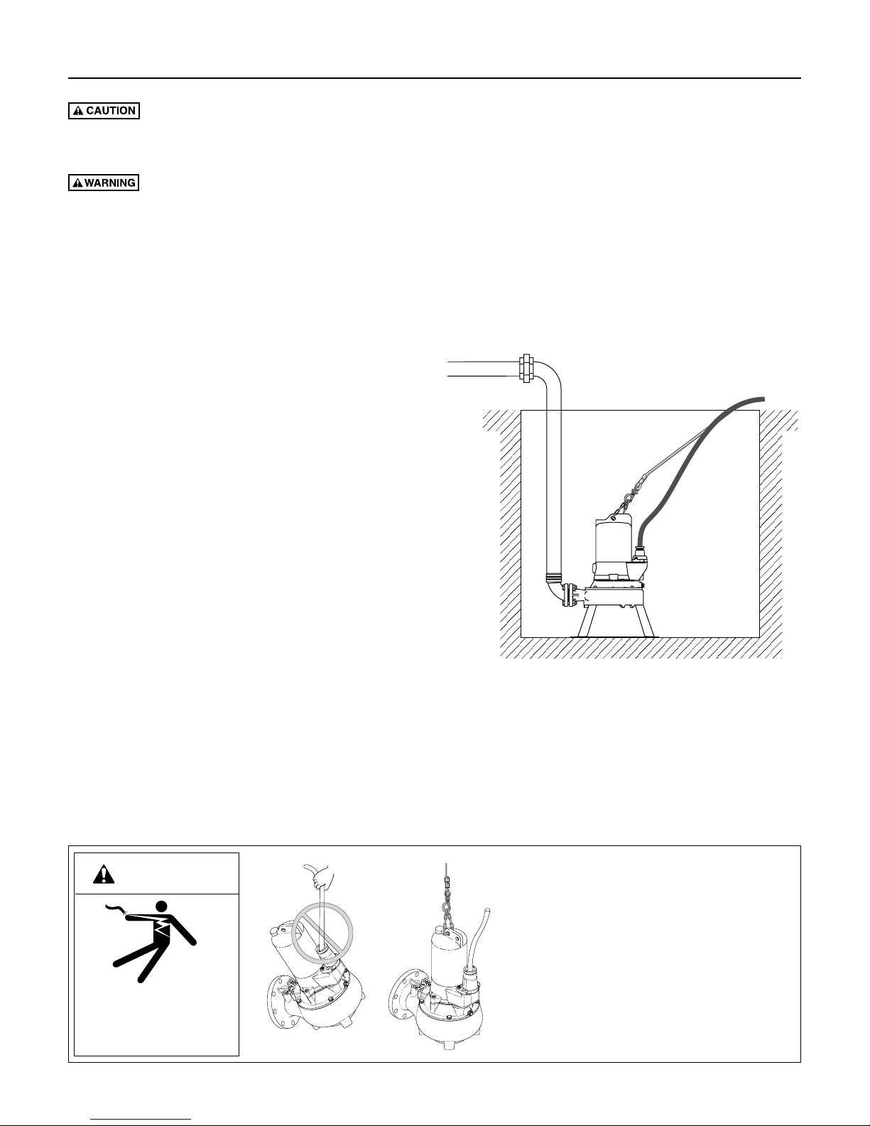
Install the pump as a free-standing unit, with a pipe
union in the discharge piping to allow removal for
servicing. Figure 1depicts a typical sewage pump in an
ordinary pit.
Installation
Handle with care. Check the items received against
the packing list to be sure that all equipment has been
received. Inspect the pump for shipping damage. If any is
found, file a claim with the carrier immediately.
Thank you for purchasing this Jung Pumpen product. To
help ensure years of trouble-free operation, please read
the manual carefully.
Cord Lift Warning
WARNING
Risk of electrical shock.
Can burn or kill.
Do not lift pump by power
cord.
Figure 1: Typical free-standing installation
The discharge piping must not be smaller than the pump
discharge. The pump must always be lifted by the lift-out
chain or cable and never by the power supply cable. See
Cord Lift Warning.
Risk of electrical shock and fire.
1. Attempting to lift or support the pump by
the power cord can damage cord and cord
connections, expose bare wires, and cause a
fire or electrical shock.
2. Use handle on top of pump for all lifting or
lowering of pump. Disconnect the power
to the pump before doing any work on it or
attempting to remove it from the pit.
3. Lifting or supporting the pump by the power
cord will void the warranty.
Installation 4
34
1U23
Interconnect Plug
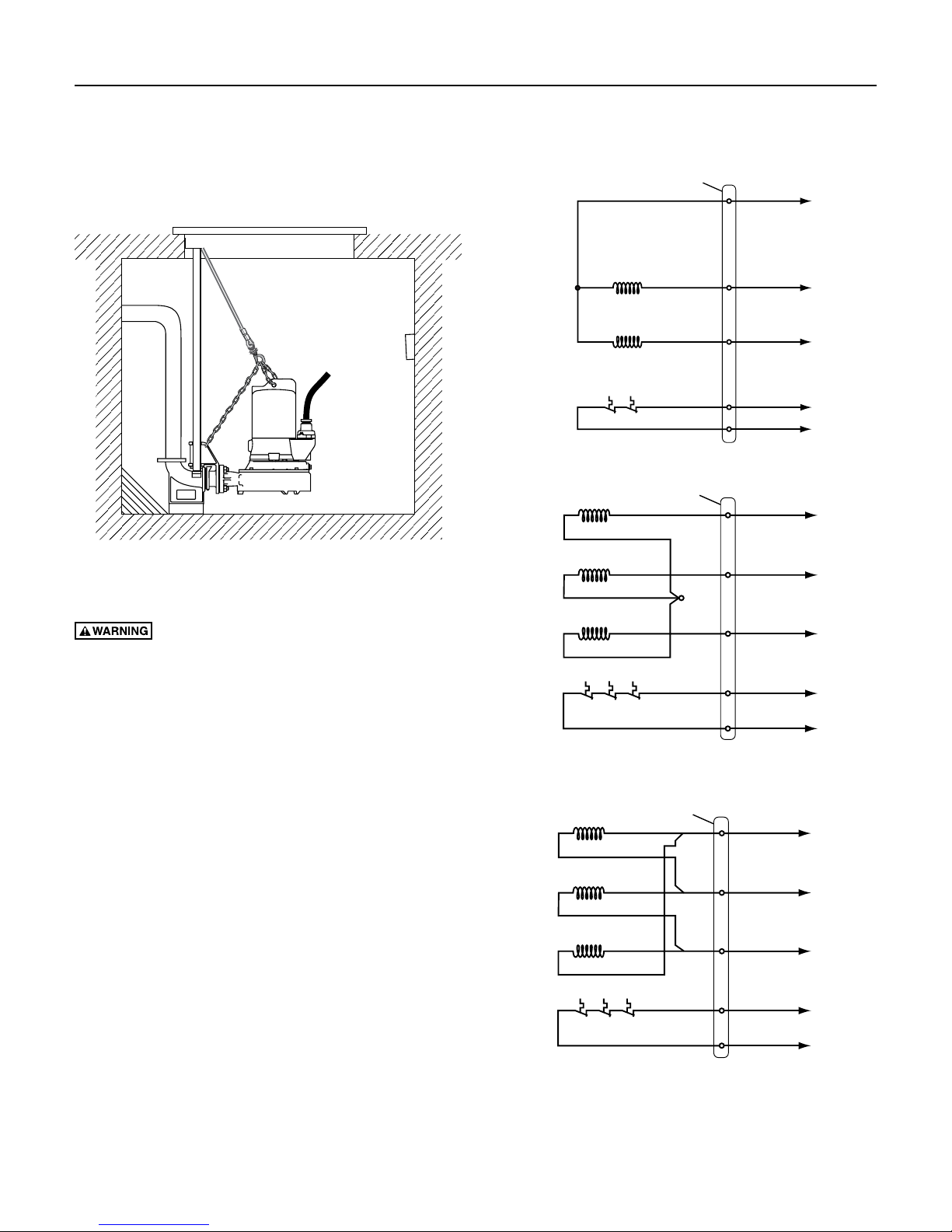
Mounting the pump on guide rails permits easy
inspection and service in permanent installations. Use
the installation instructions supplied with the guide rail
lift-out system. Place the pump opposite the influent
opening to prevent stagnant areas where solids can settle.
See Figure 2.
Figure 2: Typical installation with guide rail system for
permanent locations.
Electrical
Risk of electric shock. Can shock, burn or
kill. When installing, operating, or servicing this pump,
follow electrical safety instructions. Only trained service
personnel should install or service this pump.
1. DO NOT splice the power cord and never lay the
cable ends in water.
2. DO NOT handle or service the pump while it is
connected to the power supply.
3. DO NOT operate the pump unless it is properly
grounded. Wire the pump directly into a grounded
terminal block in an automatic float or pump
controller box for automatic operation. Connect
the pump according to all applicable codes. For
continuous operation, wire the pump directly into
the switch box.
4. Incorrect voltage can cause a fire or seriously
damage the motor and voids the warranty. Make
sure that the frequency and voltage shown on the
nameplate corresponds to the frequency and voltage
of the electrical supply. The supply voltage must be
within + 10% of the nameplate voltage. If in doubt
consult a licensed electrician.
5. Connect the pump to its own dedicated circuit with
no other load on the circuit. Figures 3, 4 & 5 show
single and three phase wiring schemes.
Motor Thermal
Protector
Interconnect Plug
U1/Z1 blackU1/Z1 black
Th
Z2 blue
HaHi
U2 red
30 white
32 white
15
22U1/Z
Z2 white
U2 red
30 orange
6
32 blue
032
Figure 3: Single phase wiring diagram
T1
T2
T3
30 32
(L1)
(L2)
(L3)
Motor Thermal
Protector
U2 grey (grey)
V2 grey (white)
W2 grey (brown)
15346
U1 black
V1 blue
X
W1 red
30 white 30 orange
32 white
U1 black
V1 white
W1 red
32 blue
Figure 4: Three phase star configuration wiring diagram
Interconnect Plug
U2 grey (grey)
Motor Thermal
V2 grey (white)
W2 grey (brown)
Protector
U1 blackU1 black
V1 blue
30 white 30 orange
15346
V1 white
W1 redW1 red
32 blue32 white
T1
T2
T3 30 32
(L1)
(L2)
(L3)
Figure 5: Three phase delta configuration wiring diagram

Installation • Operation 5
6. Use a control panel sized to match the pump. Refer
to control panel installation instructions for wiring
connection information.
7. Install the pump in accordance with all electrical
codes that apply. Install a fused disconnect switch or
circuit breaker in accordance with local codes.
8. Any alterations to internal pump circuitry must be
made using crimp connectors and professional tools.
9. The pump rotation must be clockwise (
from the top of the pump). NEVER operate it
inreverse.
If a three phase unit runs backwards, interchange
two of the three power supply wires to reverse the
motor’s direction of rotation.
– viewed
Control Panels
Risk of electric shock. Can shock, burn or
kill.Groundpumpandmotorbeforeconnectingcontrols
or power supply. Adhere to local electrical codes
governing pump and control installations.
A control panel is not included with the pump. Install
a simplex or duplex control panel (purchase separately)
for proper pump operation. Single phase pumps require
a start package, as shown in Product Specifications. A
full range of controls and switches are available from
yourdealer.
If a Jung Pumpen control panel is not used, install a
control panel with circuit breaker or fused disconnect
as required by local code. Use magnetic starters with
ambient compensated overload protection. Three phase
units require three line protection; single phase units
require only one line protection. Inadequate protection
voids the warranty.
Co ntrol Panel Overload Adjustment –
Three Phase
NOTICE: See your con trol panel in stallation and
operating instructions before adjusting overload setting.
Set the overload protective device to the nameplate full
load current.
Size the overload protective device so that the trip
current is 115% of the nameplate full load current.
Operation
Risk of cuts and possible unexpected starts.
Rotation of the cutter with hands in the cutter area can
cause loss of fingers.
keep your hands away from the pump inlet opening when
working on or handling the pump for any reason. Do not
use automatic reset controls with this pump.
Single phase units have an automatic overload protector
in the motor which will protect the motor from burning
out due to overheating/overloading. When the motor
cools down, the overload protector will automatically
reset and start the motor. This can happen at any time.
Three phase units require external overload protection.
If the overload trips frequently, check for the cause. It
could be:
• stuckimpeller
• wrong/lowvoltage
• badthermaloverloadprotector
• electricalfailureinthemotor.Ifthemotorhas
electrically failed, replace the pump.
NOTICE: Normal domestic sewage will cause very little
dulling or wear of the pump parts. However, pumping
abrasives (such as fine sand) will increase wear and
tear and may make it necessary to replace certain
pumpcomponents.
The pump is not equipped with thermostats or a leak
sensor probe. Check the oil condition in the seal
chamber quarterly in heavy duty service or annually in
light duty service.
NOTICE: Failure to monitor the oil condition voids the
warranty. Motors damaged by flooding of the motor
cavity due to seal or O-Ring failure may not be covered
under warranty.
Verify the capacity of the pump by checking the
discharge. Verify that the pump is free from any vibration
and noise.
To avoid overheating the motor for continuous operation,
the pump must be completely submerged in liquid. Set
the level switches to maintain this submerged condition.
Do not allow the pump to run in a dry sump. It will void
the warranty and may damage the pump.
Disconnect the electrical power and
Maintenance 6
Maintenance
Only qualified mechanics with proper tools and
knowledge should attempt to service this pump.
Heavy parts. Use lifting gear of appropriate
capacity positioned directly over lift point(s).
Seal Lubrication
Oil in the seal chamber should be changed after the first
300operating hours, then each 1000 hours thereafter or
annually. The oil fill/oil drain opening is labled “OHL”.
After cleaning and sanitizing the pump, drain all oil and
residue into a clean measuring container.
• Iftheoilismilkyinappearance,itiscontaminated
with water. Refill pump with clean, fresh oil, using
amounts and type shown in Maintenance. Check oil
condition again after 300 operating hours.
• Iftheoiliscontaminatedwithbothwaterand
pollutants, the main seal must be replaced and
the oil changed. Recheck oil condition after
300operating hours.
NOTICE: Whenever the main seal is being serviced,
remove oil and replace with new oil at reassembly. Use
only SAE 5W-15W (ISO 22-44) mineral oil.
The filling quantity is shown in Product Specifications.
NOTICE: Fill oil reservoir with the exact quantity of oil
specified. The pump will become inoperable if overfilled.
Cleaning the Impeller
Risk of electrical shock, cuts, and possible
unexpected starts.
keep your hands away from the pump inlet opening when
working on or handling the pump for any reason. Do not
use automatic reset controls with this pump.
1. Disconnect the electrical power supply.
2. Disconnect the discharge piping (this step is not
necessary if you have a guide-rail lift-out system).
3. Hoist the pump out of the pit using the lift-out
system or the lifting chain (not the cord) and place
the pump in a suitable area where it can be cleaned.
4. Remove all scale and deposits from the pump. Check
visual appearance of all pump housing screws and
mating surfaces. Tighten any loose fasteners.
Risk of infection. Pathogens (such
as hepatitis) can collect on pump during normal
operation. Submerge the complete pump in a
disinfectant solution (dilute chlorine bleach) for at
least one hour before disassembly.
Disconnect the electrical power and
5. Unscrew four 5 mm Allen screws attaching the
volute and remove the volute casing. It may be
necessary to tap around the parting line with a lead
or rawhide hammer to loosen the casing.
Worn impellers can have sharp edges that could cut
or scratch.
6. Carefully clean the impeller and volute surfaces.
Inspect for obvious cracks or damage.
7. Reverse step 5 to reassemble the pump.
Risk of cuts. Wear protective gloves.
Impeller Replacement
1. Remove four 5 mm Allen screws that attach the
volute and remove the volute casing. It may be
necessary to tap around the parting line with a lead
or rawhide hammer to loosen the casing.
starts. Wear protective gloves. Worn impellers can
have sharp edges that could cut or scratch.
2. Wedge the impeller with a piece of wood and
loosen the central impeller screw located in the
impellerhub.
3. Loosen the impeller by striking it gently with a lead
or rawhide hammer, then slide it off the motor shaft.
4. Clean all exposed surfaces, including motor shaft.
5. Greasetheshaftcoverontheinside.DONOTuse
grease containing graphite (like Molykote).
6. Assemble all impeller-mounting components and
tighten finger tight.
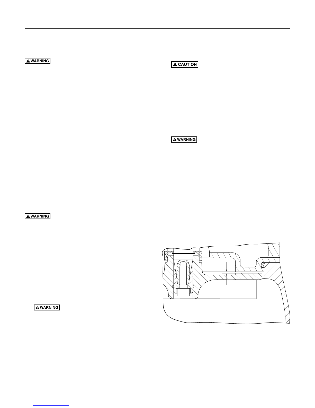
7. Slide a new impeller over impeller mount.
8. Set impeller-to-motor housing gap (X) to .007”
(2mm). See Figure 6.
Figure 6: Impeller clearance
9. Block impeller with a piece of wood and tighten
central impeller screw to 48 ft-lb (65 Nm).
10. Attach motor unit to volute casing. Finger tighten
four 5 mm Allen screws, then torque each to
5.9ft-lb (8 Nm). The cable entry point is opposite the
discharge opening.
Risk of cuts and possible unexpected
X

Maintenance 7
Main Seal Replacement
1. Follow steps 1 through 4 under “Cleaning
theImpeller”.
2. Follow steps 1 through 4 under
“ImpellerReplacement”.
3. Lay the pump on its side and remove the oil plug
from the bracket. Drain oil into a clean container
and check for water in the oil and for pollutants in
the oil.
NOTICE: Water is heavier than oil. Look for water at
the bottom of the oil. It will appear as tiny bubbles.
If there is water present in the oil, the shaft seal or
the O-Ring will need to be replaced. If there is no
water present in the oil, the shaft seal and O-Ring do
not need replacing.
4. Remove the two 8 mm capscrews that hold the
motor housing to the bracket. Tap around the parting
line with a lead hammer or rawhide mallet to loosen
the motor housing. Remove the motor housing from
the bracket.
5. Remove the oil seal and oil seal bushing from the
motor housing.
6. Remove the motor housing O-Ring and clean the
O-Ring groove.
7. Remove the seal retaining ring from the
motorhousing.
NOTICE:
and lower silicon carbide seals, two rotating silicon
carbide seals, and the spring. Be sure that you do not
scratch or mar the shaft when removing the seals. If the
shaft is marred, it must be dressed smooth with fine
emery or crocus cloth before installing new seal. Do
not reduce the shaft diameter.
8.
Pull and turn the rotating seal halves to remove them
from the motor shaft. If necessary, use a flat blade
screwdriver to help pry the seals from the shaft.
9. Unscrew four capscrews and remove the bracket
from the motor housing.
10. Use a flat blade screwdriver and very carefully pry
the lower seal half from the cavity.
11. Use a flat blade screwdriver and very carefully pry
the upper seal half from the bracket cavity.
The shaft seal consists of 5 parts - the upper
Installing the New Shaft Seal
NOTICE: Install all new O-Rings, seals, and gaskets
during reassembly. It is good practice to replace the
O-Rings each time the pump is serviced.
1. Clean the seal cavities in the bracket and
motorhousing.
2. Lubricate the seals with a very small amount of
cleanoil.
3. Inspect the shaft for nicks and scratches.
4. With finger pressure only, press the stationary seal
halves firmly and squarely into the seal cavities in
the bracket and motor housing.
NOTICE: Be sure you do not scratch the seal surface.
5. Reinstall the lower seal retaining ring.
6. Reinstall the bracket on the motor. Use a new
O-Ring. Torque 8 mm capscrews to 48 ft-lb (65Nm).
Slide the rotating seals and the spring onto the shaft.
7.
NOTICE: Be sure you do not scratch the seal surface.
Be careful that the shaft shoulder does not damage
the seal faces when they are passing over the shaft.
Make certain the polished surfaces of the rotating
seals face the mating surfaces of the stationary
sealhalves.
8. Clean the O-Ring groove in the bracket and install a
new O-Ring.
NOTICE: It is good practice to replace the O-Rings
each time the pump is serviced.
9. Reinstall the volute casing on the bracket. Torque
four Allen screws to 5.9 ft-lb (8 Nm).
10. Greasetheshaftcoverontheinside.DONOTuse
grease containing graphite
11. Assemble all impeller-mounting components and
tighten finger tight.
12. Slide impeller over impeller mount.
13. Set impeller-to-motor housing gap to .007” (2mm).
See Figure 6.
14. Block impeller with a piece of wood and torque
central impeller screw to 48 ft-lb (65 Nm).
15. Attach motor unit to volute casing. Torque four Allen
screws to 5.9 ft-lb (8 Nm).
16. Refill pump with specified amount of fresh, clean oil.
Do not overfill.
17. Position pump vertically and check for free
impellerrotation.
The pump is ready to return to service.
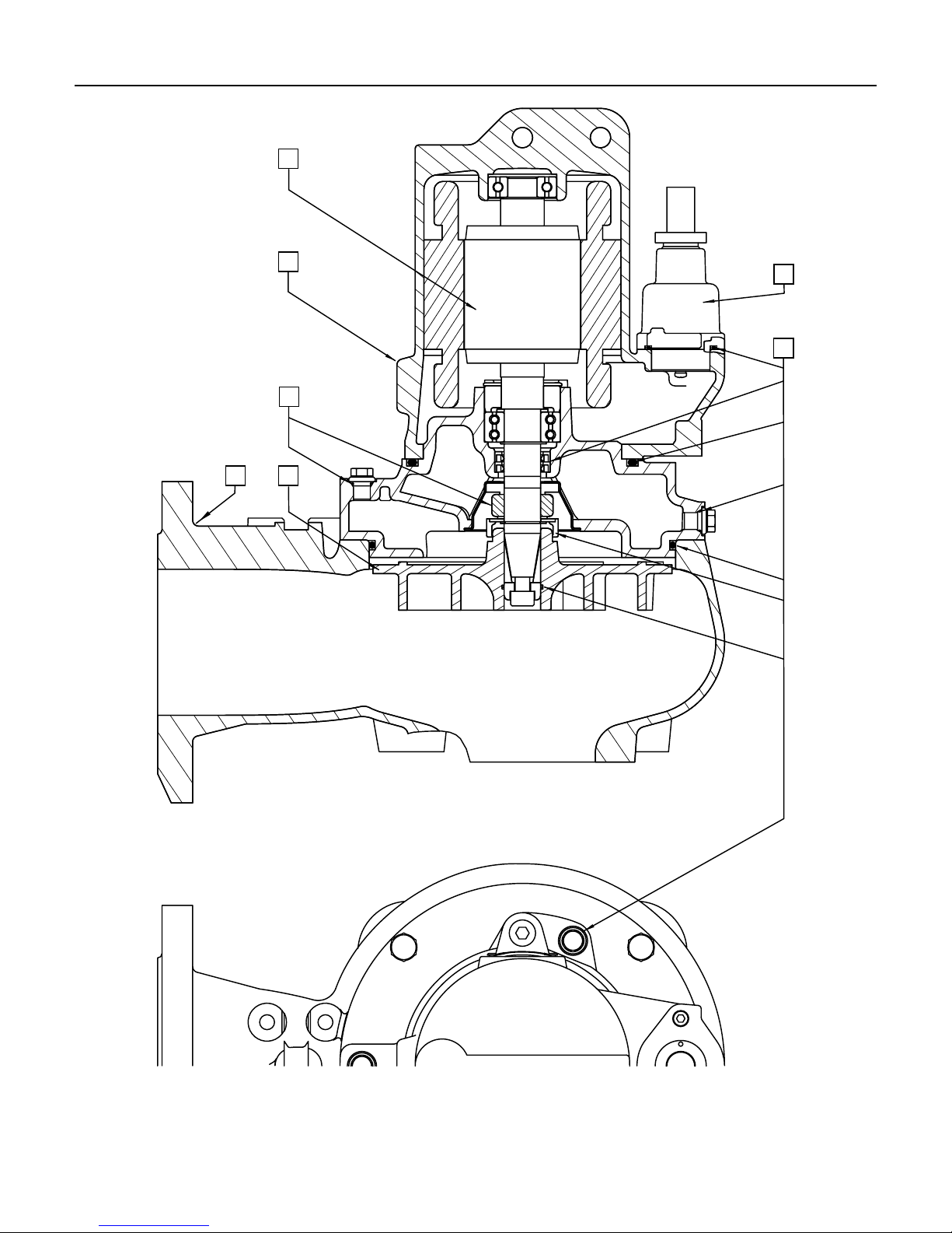
Repair Parts 8
2
1
3
4
7
8
3

Repair Parts 9
Item # -> 1 2 3 4 7 8
Model Housing with
V1D-01
V1D-21
V1D-03 RP-JP43644
V1D-43 RP-JP43645
V15D-01
V15D-21
V15D-03 RP-JP43644
V15D-43 RP-JP43645
V2D-01
V2D-21
V2D-03 RP-JP43644
V2D-43 RP-JP43645
V3D-01
V3D-21
V3D-03 RP-JP43646
V3D-23 RP-JP43911
V3D-43 RP-JP43647
V5D-43 RP-JP43902 RP-JP22733
V7D-43 RP-JP43903 RP-JP22734 RP-JP43875
* Seal Set includes all O-rings, shaft cover, supporting washer, rotary shaft seal and mechanical seal to service entire pump.
stator
RP-JP43648 RP-JP44220
RP-JP43649 RP-JP43654
RP-JP43649 RP-JP43654
RP-JP43650 RP-JP43363 RP-JP43990 RP-JP43868 RP-JP43869 RP-JP43870
Rotor Seal Set* Volute Casing Impeller Cord & Cord Entry
25’ 50’ 100’
RP-JP43091
RP-JP21754V1D-23 RP-JP43910
RP-JP43249
RP-JP21754V15D-23 RP-JP43910
RP-JP22032 RP-JP43055
RP-JP43092
RP-JP21754V2D-23 RP-JP43910
RP-JP21757 RP-JP21800 RP-JP43063 RP-JP43701
RP-JP22851 RP-JP43937
RP-JP43873
RP-JP43063 RP-JP43701 RP-JP43702
RP-JP43061 RP-JP43701
RP-JP43702
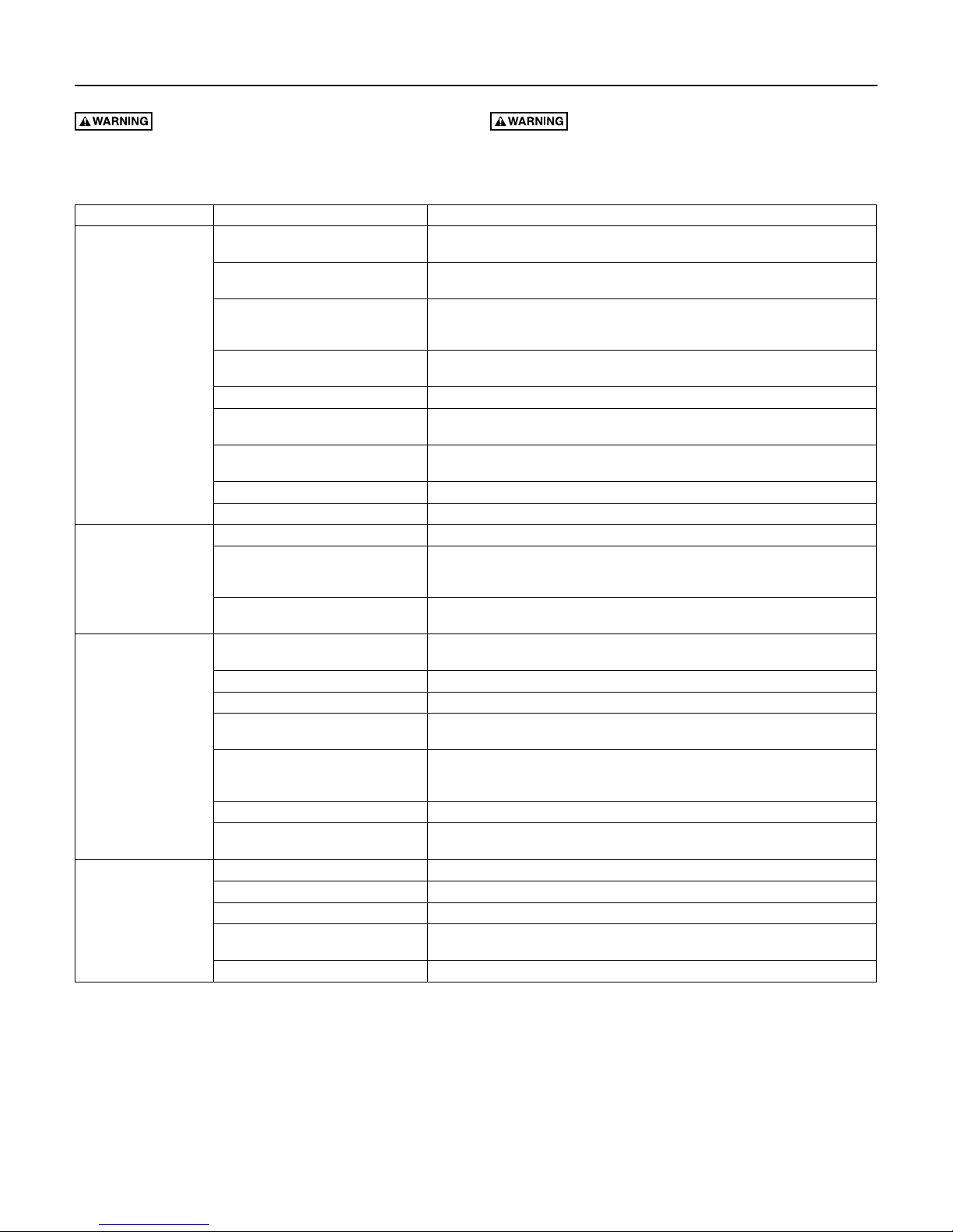
Troubleshooting 10
Risk of electric shock. Can shock, burn or
kill. Disconnect power before attempting any service or
repair work on pump.
Symptom Possible Cause(s) Corrective Action
Motor not running Motor protector tripped. Allow motor to cool. Make sure pump is completely submerged. Clear debris from volute
Open circuit breaker or blown fuse. Replace fuse or reset breaker. If circuit breaker opens repeatedly, don’t reset it - call a
Impeller clogged or binding. Check amp draw. If it is more than twice the nameplate amps, the impeller is locked.
Power cable damaged. Resistance between power cable and ground should be infinity. If any reading is less than
Bad control panel. Inspect control panel wiring. Call a licensed electrician.
Defective liquid level switch. With switch disconnected from power, check continuity through switch while activating
Not enough liquid in wet well to activate
controls.
Liquid level cords tangled Untangle cords for free operation.
Automatic controls defective Try running pump in manual mode. If it runs, the automatic control is at fault.
Pump runs continuously Liquid level control cords tangled Untangle cords for free operation.
Pump is airlocked. Stop pump for about one minute, then restart. Repeat stopping and starting until the
Flow in matches or exceeds the pump’s
capacity.
Little or no effluent
delivered from pump
Pump cycles constantly No discharge check valve installed. Install discharge check valve.
Check valve plugged, stuck shut, or
installed backwards.
System head excessive. Consult dealer.
Pump suction plugged. DISCONNECT POWER, pull pump, inspect, and clear as needed.
Wrong voltage or not wired correctly. Check pump’s rotation; check nameplate voltage against supply voltage (they must
Pump is air locked. Stop pump for about one minute, then restart. Repeat stopping and starting until the
Worn or damaged impeller. DISCONNECT POWER, pull pump and inspect impeller. Replace if necessary.
Liquid level controls incorrectly installed
or defective.
Discharge check valve stuck open. Repair or replace check valve as necessary.
Sewage wetwell too small. Consult dealer.
Liquid level controls incorrectly installed
or defective.
Pump too small for inlet flow. Consult dealer about larger pump or second pump.
Allow the liquid to rise several inches above the switch-on level.
A larger pump or more pumps may be needed.
Make sure check valve is installed correctly (flow arrow should point away from pump)
Reposition or replace as necessary.
Reposition or replace as necessary.
Keep hands away from pump suction inlet when working
on or servicing pump.
and impeller. Check for high amp draw.
licensed electrician.
Bearings and shaft may be damaged. DISCONNECT POWER, clear debris from volute,
impeller, and cutter as needed.
infinity, call a licensed electrician.
liquid level switch. Replace switch if necessary.
airlock clears. If the airlock persists, DISCONNECT POWER, pull the pump and drill a
1/8” hole in the discharge pipe between the pump discharge and the check valve.
and functioning correctly.
match); consult a licensed electrician.
airlock clears. If the airlock persists, DISCONNECT POWER, pull the pump and drill a
1/8” hole in the discharge pipe between the pump discharge and the check valve.
Risk of cuts and possible unexpected starts.

Warranty • Product Specifications 11
Limited Warranty
Jung Pumpen warrants to the original consumer purchaser (“Purchaser” or “You”) of Jung Pumpen Effluent Pumps, Sewage Pumps, and Package
Systems, that they will be free from defects in material and workmanship for the Warranty Period of 12 months from date of manufacture.
Our warranty will not apply to any product that, in our sole judgement, has been subject to negligence, misapplication, improper installation, or
improper maintenance. Without limiting the foregoing, operating a three phase motor with single phase power through a phase converter will void the
warranty. Note also that three phase motors must be protected by three-leg, ambient compensated, extra-quick trip overload relays of the recommended
size or the warranty is void.
Your only remedy, and Jung Pumpen’s only duty, is that Jung Pumpen repair or replace defective products (at Jung Pumpen’s choice). You must pay all
labor and shipping charges associated with this warranty and must request warranty service through the installing dealer or selling distributor as soon
as a problem is discovered. No request for service will be accepted if received after the Warranty Period has expired. This warranty is not transferable.
EXCEPTIONS: Special Application Pumps, Filtered Effluent Pumps, Grinder Pumps, 2-1/2” Sewage Pumps, and Lift Systems are warranted for a period
of 12 months from date of purchase or 18 months from date of manufacture, whichever comes first.
Jung Pumpen SHALL NOT BE LIABLE FOR ANY CONSEQUENTIAL, INCIDENTAL, OR CONTINGENT DAMAGES WHATSOEVER.
THE FOREGOING LIMITED WARRANTIES ARE EXCLUSIVE AND IN LIEU OF ALL OTHER EXPRESS AND IMPLIED WARRANTIES, INCLUDING BUT
NOT LIMITED TO THE IMPLIED WARRANTIES OF MERCHANTABILITY AND FITNESS FOR A PARTICULAR PURPOSE. THE FOREGOING LIMITED
WARRANTIES SHALL NOT EXTEND BEYOND THE DURATION EXPRESSLY PROVIDED HEREIN.
Some states do not allow the exclusion or limitation of incidental or consequential damages or limitations on the duration of an implied warranty, so the
above limitations or exclusions may not apply to You. This warranty gives You specific legal rights and You may also have other rights which vary from
state to state.
This Limited Warranty is effective June 1, 2011 and replaces all undated warranties and warranties dated before June 1, 2011.
Jung Pumpen
293 Wright Street, Delavan, WI 53115
Phone: 800-642-5930 • jungpumpen-us.com
Model HP PHASE Frequency Voltage* F.L.C. R.P.M. Max. head Max. flow rate Weight †Cable SOOW START PAK
Hz Volts Amp 1/min ft m GPM LPM lbs kg
V1D-01
V1D-03 3 1685 Not Required
V1D-21 1
V1D-23
V1D-43 460 3.5
V15D-01
V15D-03 3 9.7 Not Required
V15D-21 1
V15D-23
V15D-43 460 4
V2D-01
V2D-03 3 10.7 1620 Not Required
V2D-21 1
V2D-23
V2D-43 460 4.6
V3D-01
V3D-03 3 13.6 1670 39 12 12/6AWG12 Not Required
V3D-21 1
V3D-23
V3D-43
V5D-43
V7D-43
* Input voltage ±10%
† Weight with 25ft (7.6m) cable. Add 7lb (3.2kg) for each additional 25ft (7.6m).
‡ Oil chamber capacity is 61in
1.5
‡
‡
7.5 12.3 1670 52 16 748 2831 258 117
1
1
3
1
3
1
2
3
1
3
3
5 10.2 1680 44 13 660 2498 249 113
60
3
(1000cc) except for V5D and V7D, which is 103.7in3 (1700cc)
200 9
230
200
230
200
230
200
230
460
13.3
11.6 SPGV-10
17.2 1650
15.5 1675 SPGV-12
20.5 1720 36 11
18.5 1720 36 11 10/6AWG10 SPGV-14
12.5
1680
8 1680 SPGV-8
6.2
1685 Not Required
1675 23 7 352 1332
7.4
8.7
1620 Not Required
1670 39 12
7
16 5 264 999
108 49 12/6AWG12
31 9 396 1499
484 1832 117 53
SPGV-7
SPGV-9
Not Required
SPGV-11
10/6AWG10 SPGV-13
12/6AWG12 Not Required
 Loading...