

Page 1

B 40584-40-1408 www.jung-pumpen.de
DE Original-Betriebsanleitung
EN Instruction Manual
FR
Instructions de service
NL Gebruikshandleiding
IT Istruzioni per l‘uso
PL Instrukcja eksploatacji
CZ Návod pro provoz
SK Návod na prevádzku
HU Üzemeltetési útmutató
JUNG PUMPEN US
US 62
US 102
US 152 US 73 H
US 103 H
US 73
US 103
US 153 US 151
US 251
US 253
US 75
US 105
US 155
Page 2

7
ENGLISH
You have purchased a product made by JUNG
PUMPEN and with it, therefore, also excellent quality and service. Secure this service
by carrying out the installation works in accordance with the instructions, so that our
product can perform its task to your complete
satisfaction. Please remember that damage
caused by incorrect installation or handling
will adversely affect the guarantee.
Therefore please adhere to the instructions in
this manual!
As with all electrical devices, this product
can also fail to operate due to an interruption
in the electricity supply or due to a technical defect. If this could result in damage, a
mains-independent alarm system must be
installed. Depending on the application, you
may also wish to install an emergency power
generator, or a second system as a back-up.
SAFETY
INSTRUCTIONS
This instruction manual contains essential
information that must be observed during
installation, operation and servicing. It is
therefore important that the installer and
the responsible technician/operator read this
instruction manual before the equipment is
installed and put into operation. The manual
must always be available at the location where the pump or the plant is installed.
Failure to observe the safety instructions can
lead to the loss of all indemnity.
In this instruction manual, safety information
is distinctly labelled with particular symbols.
Disregarding this information can be dangerous.
General danger to people
Warning of electrical voltage
ATTENTION!
Danger to equipment and operation
Qualification and training of
personnel
All personnel involved with the operation,
servicing, inspection and installation of the
equipment must be suitably qualified for this
work and must have studied the instruction
manual in depth to ensure that they are sufficiently conversant with its contents. The
supervision, competence and areas of responsibility of the personnel must be precisely
regulated by the operator. If the personnel do
not have the necessary skills, they must be
instructed and trained accordingly.
Safety-conscious working
The safety instructions in this instruction
manual, the existing national regulations
regarding accident prevention, and any internal working, operating and safety regulations
must be adhered to.
Safety instructions for the
operator/user
All legal regulations, local directives and safety regulations must be adhered to.
The possibility of danger due to electrical
energy must be prevented.
Leakages of dangerous (e.g. explosive, toxic,
hot) substances must be discharged such
that no danger to people or the environment
occurs. Legal regulations must be observed.
Safety instructions for installation, inspection and maintenance works
As a basic principle, works may only be carried out to the equipment when it is shut
down. Pumps or plant that convey harmful
substances must be decontaminated.
All safety and protection components must
be re-fitted and/or made operational immediately after the works have been completed.
Their effectiveness must be checked before
restarting, taking into account the current
regulations and stipulations.
Unauthorised modifications,
manufacture of spare parts
The equipment may only be modified or altered in agreement with the manufacturer. The
use of original spare parts and accessories
approved by the manufacturer is important
for safety reasons. The use of other parts can
result in liability for consequential damage
being rescinded.
Unauthorised operating methods
The operational safety of the supplied equipment is only guaranteed if the equipment is
used for its intended purpose. The limiting
values given in the "Technical Data" section
may not be exceeded under any circumstances.
Instructions regarding accident prevention
Before commencing servicing or maintenance
works, cordon off the working area and check
that the lifting gear is in perfect condition.
Never work alone. Always wear a hard hat,
safety glasses and safety shoes and, if necessary, a suitable safety belt.
Before carrying out welding works or using
electrical devices, check to ensure there is
no danger of explosion.
People working in wastewater systems must
be vaccinated against the pathogens that
may be found there. For the sake of your
health, be sure to pay meticulous attention to
cleanliness wherever you are working.
Make sure that there are no toxic gases in the
working area.
Observe the health and safety at work regulations and make sure that a first-aid kit is to
hand.
In some cases, the pump and the pumping
medium may be hot and could cause burns.
For installations in areas subject to explosion
hazards, special regulations apply!
This appliance can be used by children aged
8 years or over and by persons with limited
physical, sensory or intellectual capabilities,
or with limited experience and knowledge,
provided that they are supervised or have
been instructed in the safe use of the appliance and are aware of the dangers involved.
Children must not be allowed to play with the
appliance. Cleaning and user maintenance
must not be carried out by children unless
they are supervised.
Page 3

8
ENGLISH
The pump must only be connected
to outlets that are installed according to specifications and are protected with at
least 10 A (slow) and FI-safety switches
(30mA).
APPLICATION
Submersible pumps from the US series are suitable for pumping domestic
waste water without stones.
When using the pumps, the relevant national laws, regulations and stipulations
must be adhered to, for example:
∙ Domestic contaminated and waste
water (e.g. EN 12056 in Europe)
∙ Installation of low voltage systems
(e.g., VDE 0100 in Germany)
For non-standard utilisation conditions,
further regulations must be observed
(e.g. VDE 0100 in Germany, part 701:
bathrooms and shower rooms; part
702: swimming pools and fountains and
part 737: outdoor use).
Where no explosion protection is stipulated for the pumping of foul wastewater at the installation location, US 75,
US 105, US 155 may also be used.
Modes of operation
with the pumped medium at a temperature of 104°F (40°C) or 194°F (90°C)
in the case of HE and HES hot water
pumps:
Motor submersed: continuous operation S1
Motor at the surface: short duration
operation S2; see “Technical Data”
Motor at the surface; intermittent operation S3; see “Technical Data”
The submersible pump is frost-resistant
down to -20°C when stored in dry condi
tions. When installed, however, it must
not be allowed to freeze in the water.
Transport
The pump must always be lifted by the handle and never by
the power supply cable! The
pump should only be lowered into deeper chambers or pits using a rope or
chain.
Dimensions [mm]
H B T BS TS
US 62 380 190 210 225 325
US 73 380 195 210 230 325
US 75 395 200 230 240 335
US 102 410 190 210 225 325
US 103 410 195 210 230 325
US 105 425 200 230 240 335
US 151 360 220 310
US 152 435 190 210 225 325
US 153 435 190 210 225 325
US 155 450 200 230 240 335
US 251 360 220 310
US 253 400 190 280
Pumps with special float assembly,
JP44795
H BS TS
US 62, US 73 380 255 280
US 75 395 205 290
US 102, US 103 410 255 280
US 105 425 265 290
US 152, US 153 435 255 280
US 155 450 205 290
Switching points On - Off for an attached control
● ○ ● ○
US 62, US 73
240 125 155 105
US 75
255 140 170 120
US 102, US 103
270 155 185 135
US 105
285 170 200 150
US 152, US 153
295 180 210 160
US 155
310 195 225 175
ELECTRICAL
CONNECTION
Only qualified electricians may
carry out electrical works to
the pump or the controls.
The relevant standards (such as EN
standards), country-specific regulations (such as VDE in Germany), and the
regulations of the local power supply
companies must be observed.
Attention ! Never put the mains plug or
a free lead end in water! If water gets
into the plug, this can cause malfunctions and damage.
Observe the operating voltage (see the
type plate)!
The pump is provided with a winding thermostat. In case of unacceptably high temperatures it switches off
the pump to protect it against possible
damage. Unacceptably high temperatures may result e.g. from dry running
or mechanical or electrical overload.
The pump is switched on again
automatically after cooling
down - risk of injury! For this
reason, always disconnect the device
from the mains before remedying the
fault! In order to do this, unplug the
pump from the mains supply or remove
the pre-fuses of the pump controls!
US 62 to US 105
Observe the operating voltage (see the
type plate)! Only connect the pump to
sockets that have been installed properly in accordance with the regulations
and are fitted with a 16 A (delay) fuse.
Pumps without built-in level control can
also be operated automatically through
the use of our level controls. Our ready
to connect level controls can be installed without specific electrotechnical
skills.
US 151 to US 253
Observe the operating voltage (see the
type plate)! Only connect the pump to
sockets that have been installed properly in accordance with the regulations
and are fitted with a 16 A (delay) fuse.
The pump must only be operated with
the standard motor protection plug.
Models without motor protection plug
must only be operated using the level
controls with integrated motor protection that are approved by JUNG
PUMPEN. These pumps must be connected by a qualified electrician.
Page 4
9
ENGLISH
The overload protection (only for D and
DS) must be set to the nominal current
of the pump (see type plate) + 10%. If
the motor protection plug or the level
control require to be opened in order to
reset or set the overload protection, this
must only be done by a qualified electrician!
Disconnect the device or the
pump from the power supply
before opening!
If there is a blockage in the pump, the
overload protection may be triggered.
After rectifying the fault the "reset" button on the motor protection plug must
be pressed to switch the pump on again.
Pumps which are operated with a separate level control have the overload protection in the level control.
Rotational direction
The rotational direction must be
checked before installation! If the rotational direction is correct, the start-up
jolt should be in the opposite direction
to the rotational direction arrow on the
motor housing. The wrong rotational
direction is also indicated if the pump
performs inadequately when installed,
or if loud noises can be heard during
operation. If the rotational direction
is wrong, 2 phases of the supply cable
must be swapped over.
The start-up jolt can be very
forceful.
INSTALLATION
The pump must be installed as shown
in the examples. For installations in
accordance with DIN EN 12056-4, the
pressure pipe must be laid in a loop
above the local backflow level and protected with a backflow prevention valve.
A correspondingly larger diameter pipe
should be used for longer pressure
pipelines to avoid pipe friction losses.
In contrast to pumps with built-in level control, the ON and OFF switching
heights of pumps without built-in level
control are variable by the use of a separate level control.
Permanent venting of the ring housing
may be necessary if the pump runs dry
from time to time (pressure outlet surfaced). This can occur for example if the
residual water in the collecting chamber evaporates or if the pump runs in
“snore” mode during the test run.
To vent the pump housing on pumps US
151, US 251 and US 253 the pressure
pipe must be drilled above the pressure
outlet to provide a 6 mm drill-hole. On
all other pumps, the M8 hexagon socket
screw under the (brass) oil screw must
be removed.
Attention!If the pump is malfunctioning, part of the contents of the oil reservoir could escape into the pumping
medium.
Dimensions of sump
Single installation with pump base: 40
x 50 cm
Single installation with guide rail system: 40 x 70 cm
Duplex installation: 70 x 70 cm
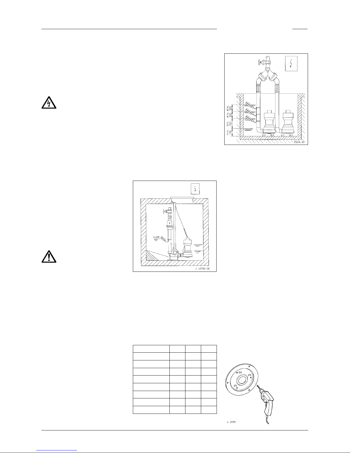
Example of installationwith guide rail
system for pumping stations at a permanent location.
Installation:Fix the coupling base firmly to the floor of the collection chamber
using wall plugs and then mount the
guide rail. Next, install the pressure
pipe including the necessary fittings,
such as the non-return valve and shutoff valves.
Finally, fit the pump with the screwedon coupling catch onto the guide rail
and lower it into place using a chain
fixed to the handle.
ON OFF
ALARM
US 62, US 73 265 150 > 385
US 102, US 103 295 180 > 415
US 75 260 145 > 380
US 105 290 175 > 410
US 155 315 200 > 435
US 152 and 153 320 205 > 440
US 151 and 251 > 270 > 120 > 370
US 253 > 270 > 120 > 370
Example of installation with pump base
Attention! The floats of the level control
and alarm system are installed so that
they are freely movable but not under
the inlet. Please observe the minimum
distances. The controls must only be
installed in a dry and well ventilated
room!
Mobile operation
For safety reasons, mobile operation is
only allowed with a foot strainer. In the
case of pumps without a standard foot
strainer, a separate foot strainer must
be ordered and fitted under the pump in
place of the three base feet.
If a hose is used as a pressure line,
care must be taken to ensure that for
every pumping operation the hose is
completely empty before the pump is
submersed. Any residual liquid would
obstruct the ventilation of the pump
housing and therefore also hinder the
pumping operation. For the same reason, the pump would not operate if
it was switched on before being submersed.
Flushing device
(not applicable for US 151 and US 251).
The pump can keep the intake section at
the bottom of the chamber clear of deposits to a large extent if you carry out
a small modification. This reduces the
performance of the pump only insignificantly.
This modification is carried out as
follows:
Detach the
foot strainer
or the 3 base
feet and remove the cover. Carefully
drill a hole
Page 5

10
ENGLISH
into the 3 markings with the ø 8 symbols. Deburr the drill-holes. Re-attach
the cover with the round sealing ring
and the foot strainer or base feet.
MAINTENANCE
We recommend that you service the
equipment in accordance with EN
12056-4.
To ensure continued reliability of service, we recommend that you take out a
service contract.
Before carrying out any works:
disconnect the pump and the
controls from the mains and
take steps to ensure that no one else
can reconnect them to the power supply.
Check the rubber hose for me-
chanical or chemical damage.
A damaged or kinked hose
must be replaced.
When using a chain to lift the
pump, please observe the rel-
evant national regulations regarding accident prevention. Lifting
gear must be checked regularly by an
expert in accordance with the legal regulations.
Oil check
The oil reservoir is sealed on the outside
with a brass screw. In order to check the
mechanical seal, the oil, including any
residue, must be drained from the oil
reservoir and collected in a clean measuring container.
∙ If the oil is contaminated with water
(milky), an oil change must be carried out. Check again after a further
300 operating hours, but at the very
latest after 6 months!
∙ However, if the oil is contaminated
with both water and pollutants, then
not only the oil must be replaced, but
the mechanical seal as well.
For monitoring the oil reservoir, it is also
possible to retrofit the electrode of our
“DKG” seal leak control device in place
of the brass screw on the oil reservoir.
Changing the oil
To ensure operational reliability, the
first oil change should be carried out
after 300 operating hours, with further
oil changes carried out after every 1000
operating hours.
If the number of operating hours is very
low, an oil change should still be carried
out at least once a year.
If wastewater with strongly abrasive
constituents is being pumped, the oil
changes should be carried out at correspondingly shorter intervals.
Use HLP hydraulic mineral oil, viscosity
class 22 to 46, e.g. Mobil DTE 22, DTE
24, DTE 25, to replace the oil in the oil
reservoir.
The quantity of oil required is 700 cm³
for the US 253, 500 cm³ for the US 251
and US 251 and 300 cm³ for all other
US pumps.
Attention! The oil reservoir must only
be filled with the specified quantity of
oil. Overfilling will result in the pump
being rendered inoperable.
Cleaning
The foot strainer prevents coarse impurities from entering the pump. Regular
cleaning of the float and the foot strainer ensures optimum performance and
operation.
To clean the impeller in the event of
an obstacle or blockage, the hexagon
socket screws on the underside of the
pump must be removed and the foot
strainer or cover must be levered off.
On pumps with a 10 mm free passage,
the wear plate must be removed. The
impeller can now be cleaned.
Worn impellers can have sharp
edges.
Tightening torque MAfor A2 screw materials
for M 6 M
A
= 8 Nm
for M 8 MA = 20 Nm
for M 10 MA = 40 Nm
for M 12 MA = 70 Nm
Quick tips for remedying
faults
No pump operation
∙ Check mains current (do not use a
pin gauge)
∙ Fuse faulty = may be too weak (please
refer to Electrical Connection)
∙ Mains supply cable damaged = repair
to be carried out by manufacturer
only
Pump runs but does not pump
∙ Empty the pressure pipe or hose to
allow the non-return valve to open
and the air to escape from the pump
housing.
Impeller blocked
∙ Solids and fibrous matter have be-
come lodged in the pump housing =
clean
Decreased pumping performance
∙ Pump housing obstructed = clean
∙ Impeller worn = replace
∙ Wrong direction of rotation (for a
three-phase current) = ask a qualified electrician to change 2 phases of
the supply line
 Loading...