

Page 1

O
O
p
p
err
e
attii
a
n
n
g
g
M
M
a
a
LEVEL MAGIC
transmission processor
digital audio processing
n
u
n
TM
u
all
a
Level Magic LT
jjuunnggeerr aauuddiioo
Junger Audio Studiotechnik GmbH
Justus-von-Liebig-Str. 7 — 12489 Berlin — Germany
phone: +49 30 677721-0 — fax: +49 30 677721-46
www.junger-audio.com
release 1.1
Page 2

Page 3

FOREWORD
Thank you for buying and using the 2-channel Digital Audio
Level Processor Level Magic LT.
You have acquired the latest generation of digital dynamic
range processing, a piece of equipment which is unique in its
design and specification.
Please read this manual carefully to ensure you have all the
information you need to use the Digital Audio Level Processor
Level Magic LT.
The unit was manufactured under highest industrial standards
and went through extensive quality control checks before it was
supplied.
If you have any comments or questions about installing, settingup or using the Level Magic LT, please do not hesitate to
contact us.
0
Page 4

1
2
2-1
2-2
3
3-1
3-2
3-3
3-4
3-5
3-6
3-7
3-7-1
3-7-2
3-8
3-9
4
4-1
4-2
CONTENTS
2. Functional description
2.1. Basic description
2.2. Block diagram
3. Installation
3.1. Unpacking the unit
3.2. Power supply
3.3. Connections
3.4. Rack mounting
3.5. Operation savety
3.6. Audio connections
3.7. Remote Control
3.7.1. GPI
3.7.2. TALLY
3.8. LAN interface
3.9. USB connector
4. Location and Controls and Connectors
4.1. Front panel
4.2. Rear panel
Page 5

5. Operation
5.1. Junger Terminal (CD-Rom Configurator)
5.1.1. Network configuration
5.1.2. Web interface/Setup of the IE 7.x
5.1.3. Password management
5.1.4. Initialization / factory defaults
of the web controller
5.1.5. Reboot of the Web Controller
5.2. Web interface
5.2.1. Login
5.2.2. Maintenance
5.2.3. Settings
5.3. Level Magic
TM
Introduction and Reference Guide
6. Technical specifications
7. Warranty and service information
8. Level Magic
TM
LT – Quick Start
5
5-1
5-1-1
5-1-2
5-1-3
5-1-4
5-1-5
5-2
5-2-1
5-2-2
5-2-3
5-3
6
7
8
Page 6

Page 7

FUNCTIONAL DESCRIPTION
The Level MagicTM LT Digital Dynamics Processor provides
automated level control, both Transient Control and AGC
-that truly works!
The Level MagicTM Dynamics Processing developed by Jünger
Audio enable level managing devices like compressors, AGC
and limiters to give you precise natural control without
coloration, pumping, breathing, distortions or modulation effects.
The outstanding quality of the processing is based on the MultiLoop dynamic range control principle in combination with
adaptive controlled processing algorithms developed by Jünger
Audio.
The Level MagicTM LT is easy to operate and requires only a
limited number of settings to be made by the user to achieve
optimum results. All other parameters necessary for inaudible
processing are continuously automatically controlled in response
to changes in the program signal.
In short: The Level MagicTM LT gives you almost inaudible
processing – coupled with extraordinary ease of use.
Level Magic
Analog and AES Digital inputs and outputs
2-channels of Adaptive Audio Leveling Processing
AGC, Transient Processor and Limiter
Adjustable input gain (-20...+20 dB
Operation via Web Interface (TCP/IP)
Password protection for View-, Operator- and Admin-logins
User friendly Presets
GPI interface for Parallel Remote Control and Tally output
TM
LT features
)
2
2.1
BASIC
DESCRIPTION
Operation manual Level Magic LT, chapter 2 – Functional description
Page 8
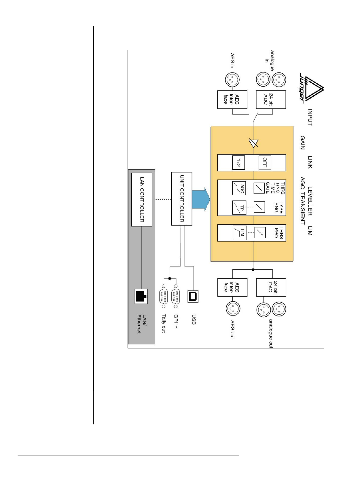
2.2
BLOCK DIAGRAM
Operation manual Level Magic LT, chapter 2 – Functional description
Page 9

INSTALLATION
The Level MagicTM LT Digital Audio Level Processor was carefully
packed at the factory with packaging designed to protect the unit from
rough handling during shipment. Please examine the packaging and its
contents carefully for any signs of physical damage, which may have
occurred in shipment.
The Level MagicTM LT Digital Audio Level Processor is classified under
the safety category Schutzklasse 1 in keeping with the VDE 0804
standards and may only be used with power supply installations built
according to these regulations.
Check to insure that the mains supply voltage details printed on the
rear panel are the same as your local mains electricity supply.
The Level MagicTM LT Digital Audio Level Processor is equipped with
standard connectors (see Chapter 3).
Before making connections to the Level Magic
power to all units that you are connecting to the Level Magic
The Level MagicTM LT Digital Audio Level Processor is a standard
19“unit (EIA format). That is 1 RU (44 mm) high. Please allow at least
3“depth in addition for the connectors on the rear panel.
When installing the unit in a 19“ rack the rear side of the unit may need
support, especially when mounting in flight cases.
The Level Magic
installed near units which produce strong magnetic fields or extreme
heat. Do not install the audio processor directly above or below power
amplifiers.
If, during operation, the sound is interrupted or displays no longer
illuminate, or if abnormal odor or smoke is detected, immediately
disconnect the power cord plug immediately and contact your dealer or
Jünger Audio.
TM
LT Digital Audio Level Processor should not be
TM
LT switch off the
TM
LT.
3
3.1
UNPACK THE UNIT
3.2
POWER SUPPLY
3.3
CONNECTIONS
3.4
RACK MOUNTING
3.5
OPERATION
SAFETY
Operation manual Level Magic LT, chapter 3 – Installation
Page 10
3.6
AUDIO
CONNECTIONS
3.7.1
GPI REMOTE
CONTROL
(PARALLEL
REMOTE)
The analogue audio inputs are RFI filtered. The analog outputs are
balanced and floating. All the audio connectors are mounted at the rear
panel. Standard XLR connectors are used wired to the AES standard:
pin 1 X Screen
pin 2 L + Audio (Live audio 0°)
pin 3 R - Audio (Return audio 180°)
Balanced connections are preferred whenever the other equipment
provides balanced inputs/outputs. All line level connections should be
wired with twin screened cable for low noise and reliability. The screen
for the input of the cable should be connected only at the signal source
end. The screen for the output cable should be connected only at he
Level Magic
An unbalanced source should still be connected to the Level Magic
TM
LT connector.
TM
LT using twin screened cable. At the signal source end add a wire
jumper so that the screen is connected to the wire that will go to PIN3
of the XLR on the other end, where it connects to the XLÖR on the
Level Magic
If the equipment following the Level Magic
TM
LT.
TM
LT only has unbalanced
inputs, then we recommend still to use a twin screened cable where
Pin1 and Pin3 are connected in the cable end at the following
equipment (that I s, not at the Level Magic
TM
LT end).
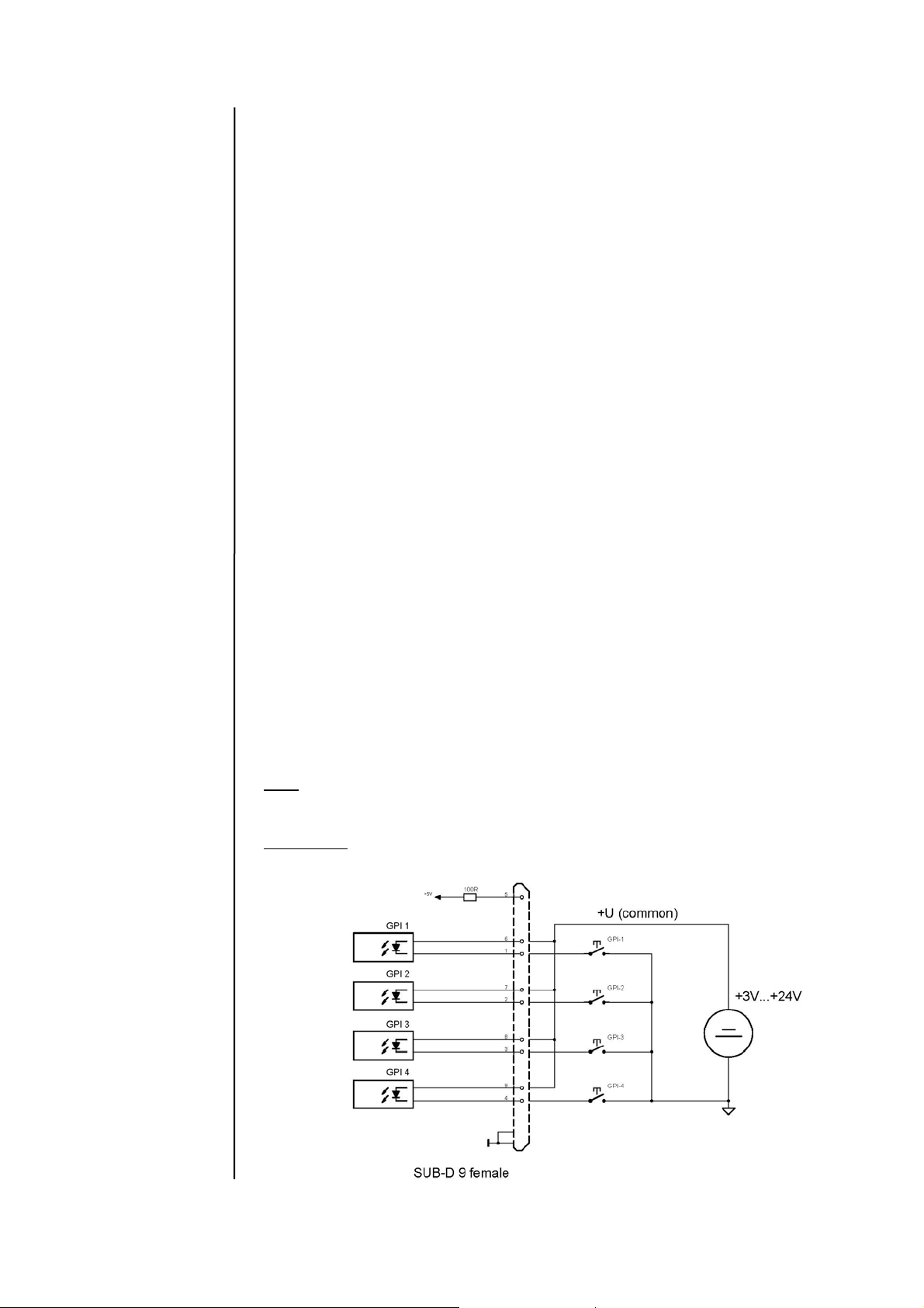
The Level Magic
TM
LT Digital Audio Level Processor can be remote-
controlled by means of parallel GPI contacts.
Use
: Remote Controlled changeover of presets and special
settings
Connector:
D-SUB 9pin, female
1
1
1
Operation manual Level Magic LT, chapter 2 – Functional description
Page 11
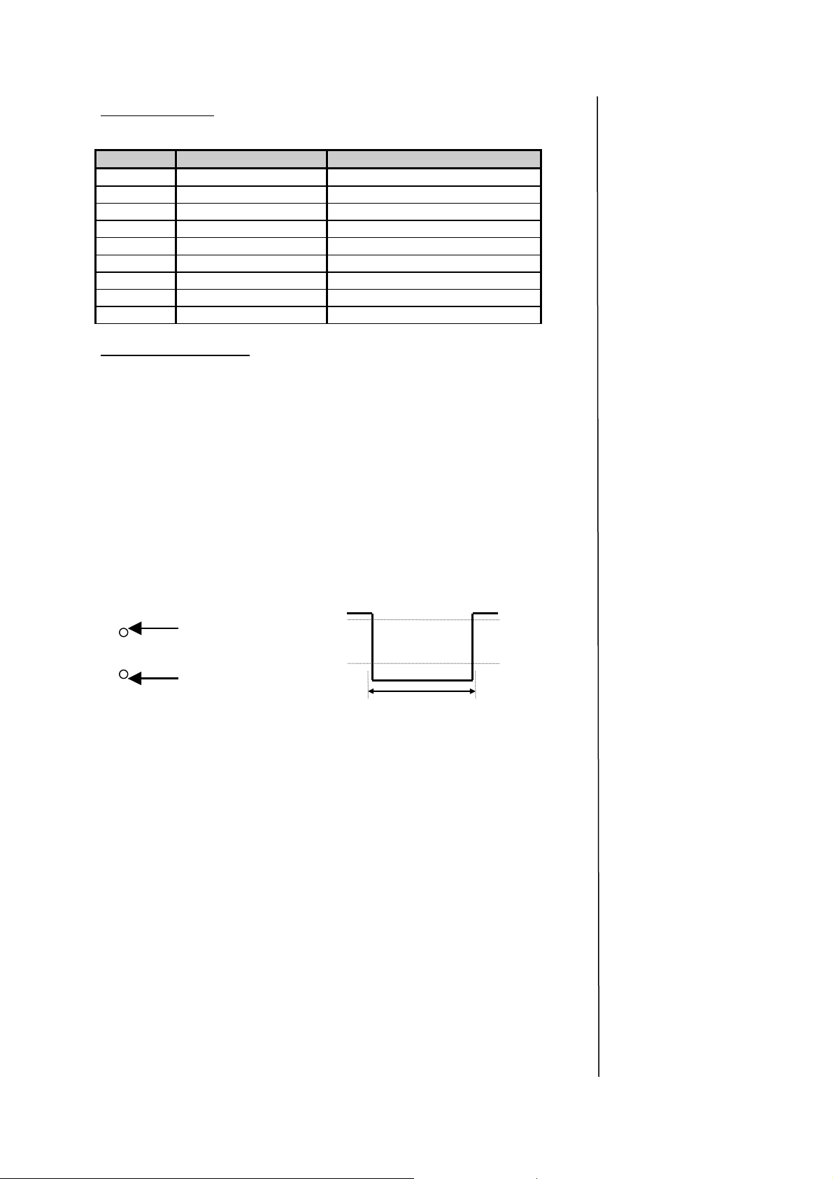
Pin assignments
,
Pin Signal name Functions
1 GPI1 in Defined via software -> setup
2 GPI
3 GPI2 in Defined via software -> setup
4 GPI
5 GPI5 in Auxiliary supply
6 GPI3 Defined via software -> setup
7 GPI
8 GPI4 Defined via software -> setup
9 GPI
Electrical specifications:
GPI input Potential free by opto-coupler, low active
Off: +3.5…+30V between GPI input
and the common pin 5.
On : less then 1.5V
Signal input level LOW: 1,5V or less for a minimum of min.
50ms
level HIGH: 3,5V or more
Characteristic Static GPI,
Pin 1-4
Pin1...13
Pin 6-9
Pin14
Pin 5
Contact to
ext. Ground
Ext. voltage
feed+3
5...30V
min. 50 ms
+3,5...30V
+1,5V
Operation manual Level Magic LT, chapter 3 – Installation
Page 12
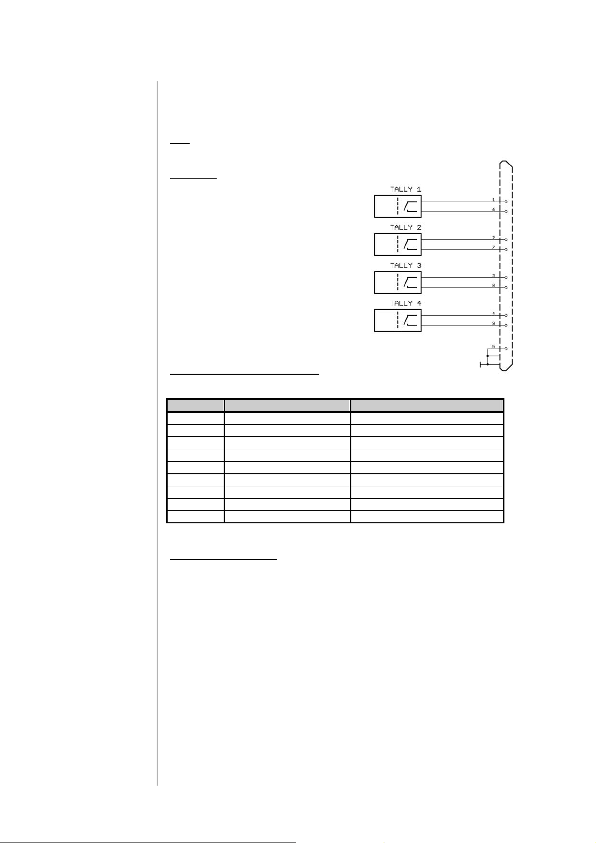
3.7.2
TALLY OUT
The Level MagicTM LT Digital Audio Level Processor can transmit
specific device statuses via parallel Tally lines.
Use
: Indication of the Unit’s basic status
Connector
female panel jack
Pin assignment of the connector :
Pin Signal name Functions
1 Tally 1 Defined via software
2 Tally 2 Defined via software
3 Tally 3 Defined via software
4 Tally 4 Defined via software
5 Ground
6 Tally 1 Common
7 Tally 2 Common
8 Tally 3 Common
9 Tally 4 Common
: D-SUB 25pin
Electrical specifications:
Tally output relay : common /
normally opened
24V - 1A
125V - 0,5A
P
= 62,5VA
max
Operation manual Level Magic LT, chapter 2 – Functional description
Page 13
The Level Magic
TM
LT Digital Audio Level Processor is set up and
operated via web interface (Internet Explorer/mozilla firefoxx). The
connection is over Ethernet.
Connector
: RJ 45 with status LEDs
8 pin panel jack
Pin assignment of the connector :
Pin Signal name Functions
1 TX + Ethernet send
2 TX - Ethernet send
3 RX + Ethernet receive
4
5
6 RX - Ethernet receive
7
8
9
Electrical specifications: 100Mbit/s auto negotiation port
This port allows remote control of the Level Magic LT by TCP/IP over
Ethernet.
The controller of the Level Magic
TM
LT acts as a CAN-controller (CANserver) for an external client. For details please refer to the Level Magic
LT web interface description (5.2 OPERATION).
For integration of the Level Magic LT into a LAN your unit hass been
given it’s own IP address (shown on a label on the rear of the unit) and
needs to be given a sub net mask of the used LAN.
For network integration of your device refer to 5.1.1 Operation –
Jünger terminal – network integration).
This port allows network configuration and password
administration.
Before you connect the Level Magic LT via USB to your PC
please install the junger terminal (CD-Rom, see 5.1 OPERATION –
junger terminal).
Connector : USB 1.0
USB connector for serial data transfer
3.8
LAN INTERFACE
3.9
USB
CONNECTOR
Operation manual Level Magic LT, chapter 3 – Installation
Page 14

Page 15
FRONT AND BACK PANEL
A
A
4
4.1.
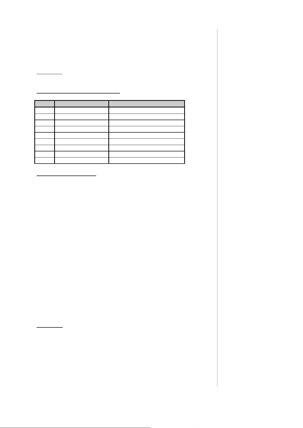
FRONT PANEL
Fig. 1: Front panel of the Level MagicTM LT
Bypass-button
If you hold the bypass-button pressed while switching on the unit, the
controller of the DSP will be initialized.
All user presets are overwritten, Parameters will be set to the TV uni
factory default.
BACKUP presets to your PC first!
ON/OFF status LED
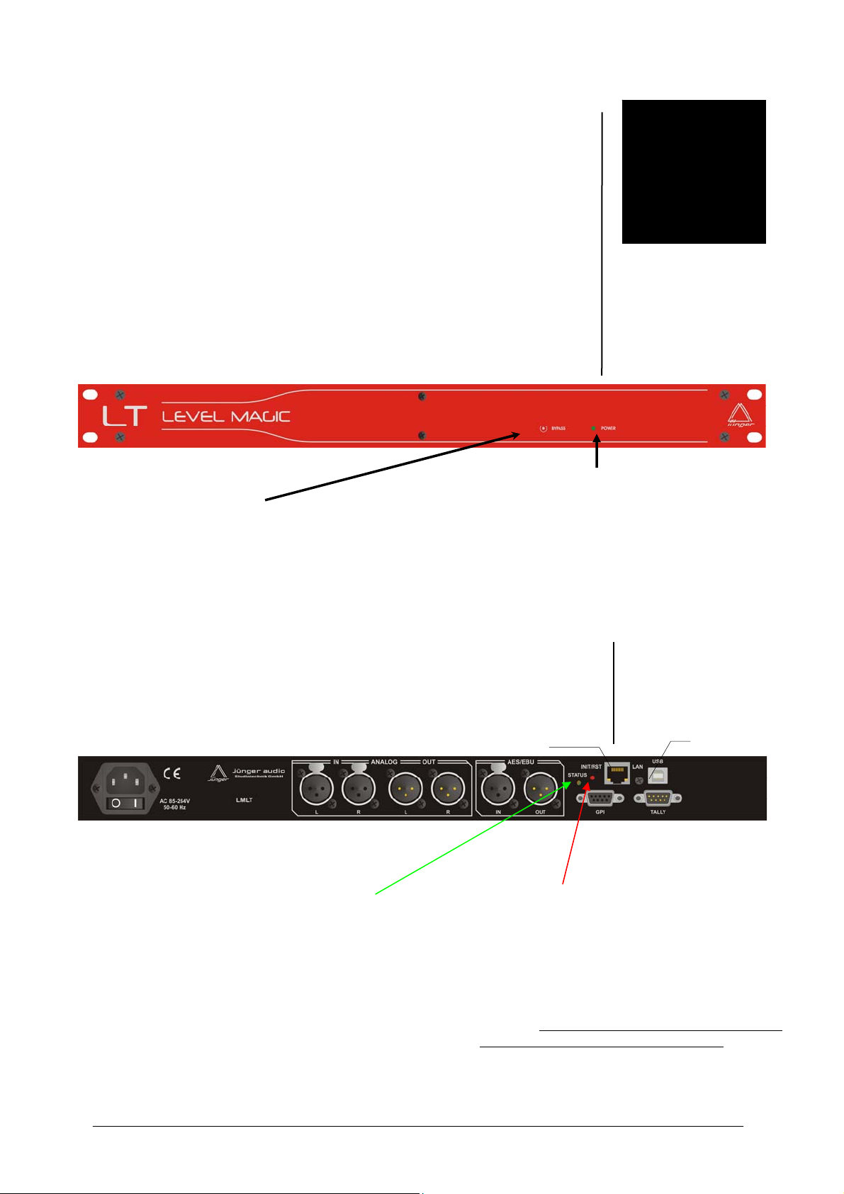
4.2.
REAR PANEL
fig. 2: rear panel Level MagicTM LT
LAN Ethernet port
USB port
nalogI/OPower supply
ES Digital I/O
GPI TALLY
port port
The green LED left of the Ethernet
connector is a status indicator that
shows if the controller is ready to work
When you press the red button for a short time a
reset of the Unit is performed, as if you had cycled
power off and on.
If you press the red button for a longer time,
the LED will begin to flash and the built-in Web
Controller will be reset. Then the factory default
network configuration of the device will be
restored. If you have changed the IP address of
the unit from that shown on the sticker, you will
not have access via your PC GUI. You will have
to change it again via Jünger terminal ( See
5.1.1).
Operation manual Level Magic LT chapter 4 –Location of parts and controls
Page 16

POWER INPUT
IEC mains input connector with integrated fuse for 85-264 V50/60 Hz
GPI
GPI-in +3,5…+30V potential-free
connector: 9pin SUB-D, female
TALLY-out open relais contact
connector: 9pin SUB-D, female
ETHERNET
Interface for LAN Controller (Web Interface)
USB
USB connector for setting the Network Configuration
ANALOG IN/OUT
Analog input is via 24 bit A/D-converters
Input floating and balanced with two female XLR connectors
Analog output is from 24 bit D/A-converters
Output floating and balanced with two male XLR connectors
DIGITAL IN
Digital input is to the AES/EBU standard format
connector: female XLR
DIGITAL OUT
Digital output is to the AES/EBU standard format
connector: male XLR
Operation manual Level Magic LT chapter 4 –Location of parts and controls
Page 17

5. OPERATION
OPERATION
Included in delivery you got a CD-Rom (junger audio Configurator).
The CD-Rom includes a program, the“junger terminal”, to setup your
device via USB. Main features are setup of the network configuration
and of the password management.
It has to be installed at your PC before you connect the Level
Magic LT via USB or Ethernet connector.
Insert the CD-ROM into your PC’s CD-drive. The setup.exe is started.
Follow the installation procedure (java1.6 included).
After installation of the “junger terminal” (icon on your desktop!) connect
the Level Magic LT via USB to your PC. (Don’t forget to power on the
device now!)
When you start the terminal program the “LM LT” will be offered in the
range of your COM connections (it is only a physical USB-connector
transmitting data). Choose the LM LT and you will get into the terminal
program:
5.1
5
junger Terminal
installation
Here you can manage the passwords for operators and administrators
(1), change the network configuration of the device (2), restore factory
defaults (3) and reboot the controller (4).
All advanced features (5,6,7,0) might be useful when you have problems
with your device. Before you use one of these features please call
Jünger Audio and you will get support by our software department.
operation manual Level Magic LT chapter 5-Operation
Page 18

5. OPERATION
5.1.1
Network
configuration
5.1.2
Web interface/
Setup of the IE
7.x
First you have to match the network configuration of the Level Magic LT
to the configuration of your PC.
(junger terminal -> 2 change network configuration)
If you are not familiar with network configuration please ask your
network administrator for help!
The default network configuration of the Jünger devices is:
IP Address: on a label at the Ethernet connector socket
at the rear of the device
Netmask: 255.255.0.0.
Gateway: 10.110 0.1.
Change this configuration into a valid IP-address, netmask and gateway
matching to your PC and - if you have a LAN - to your LAN.
After having changed the network configuration you have to reboot the
web controller (junger terminal 4 – reboot)
Please write the new IP-address of the device at the rear of the
device. Otherwise using the factory default IP-address might cause
confusion later!
If you have a LAN in your working environment you can connect the
Level Magic LT now via ethernet cable.
If you connect the Level Magic LT directly to your PC, you need an
Ethernet crossover cable (not connected 1 to 1, but 1 to 8 etc…).
Now you will be able to operate the Level Magic LT via web browser.
Just type in the new IP-address into your browser (e.g. Internet Explorer
- http://IP-address
) und you will get access to the web interface of the
device.
The web interface / GUI is based on common web technologies so
you can display it nearly everywhere. External access to the Junger
units is maintained by a dedicated 32Bit communication processor
solution. For C8k systems it fits on a C8k module, the C8702 “Frame
Controller”. 19”/1RU devices like the LMLT / d06 / d07 employing the
same hardware by a built-in piggyback, let’s call it the “Interface
Controller”. You can treat a 1RU device as a combination of C8k
modules build in one chassis.
The communication processor does not control the DSP parameters
directly. It transfers commands and data from and to a DSP control
processor which on the other hand controls the DSP parameters but
also front panel controls as well as GPI/Os. For data transfer between
the DSP control processors and the communication processor we use
the CAN bus internally. Therefore the external communication is
somewhat shielded from the audio processing by this two stage
approach so you can update the firmware image of the
communication processor without disturbing the audio processing :
operation manual Level Magic LT chapter 5 Operation
Page 19

5. OPERATION
LAN
RS232
Audio I/O
* LevelMagic
* AudioFail
* MixMatrix
* Limiter
Front panel for 19"/1RU devices
32 Bit communication processor
(C8702 frame controller)
(d06/d07 interface cont roller)
DSP
DSP -
control processor
(device controller)
(module controller)
CAN bus
The communication processor runs a HTTP (web-) server, an UDP
server, and a SNMP agent.
Over a serial 1:1 connection, (RS232: 115200, 8, N, 1, no protocol) you can
gain access to the consol interface (see Network Configuration above). It
offers low level communication for administrative and testing purposes. The
functions available from the console interface may be very from different
frame controller firmware versions.
We support the GUI functions for IE 7.x and Firefox 2.0. For proper
operations, the environment needs some settings which are not set up by
default when installing MS-Windows, so you must do change the settings:
* You must “allow cookies” from the Junger Units. Pay attention to
settings of 3
rd
party tool bars (like Yahoo) which may overwrite the
browser general settings!
* The security option “Downloads” >> “Automatic prompting for file
downloads” must be set to: “activate” in order to receive files from the
unit.
* Java Script must be allowed.
* Java Virtual Machine > 1.6 must be installed on the PC in order to
receive level meter display.
You will get it as a free download from SUN Microsystems www.java.com
* If your PC is part of a MS Domain, you must check if the LAN settings
are correct.
operation manual Level Magic LT chapter 5-Operation
Page 20

5. OPERATION
If you have manually configured your IE settings you must disable Automatic
configuration as well as the use of a proxy server for your LAN:
Tools > Internet options > Connections > LAN settings: :
Otherwise it could happen that your settings are overwritten automatically. It
is important to bypass the proxy server for local addresses.
Finally you must declare the IE (and/or Firefox) as an exception for the
Windows® Firewall in order to maintain proper UDP data transfer from and
to the JAVA applet.
operation manual Level Magic LT chapter 5 Operation
Page 21

It is very important that you disable the caching features of the browser.
Because the C8702 web pages are designed for operation in LANs. The
strategy developed for surfing the internet (saving bandwidth and time to
load pages employs caching of web site elements - the default set up of the
browser) may cause confusion for a more technical application like the
embedded controller module, because it uses a high degree of dynamically
generated elements, which must be gathered from the web server instead of
the PC memory or proxy servers.
For IE 7 you must go to:
[German version] Extras > Internetoptionen >
Allgemein > Browserverlauf > Einstellungen
[English version] Tools > Internet Options
>General > Browser history > Settings
5. OPERATION
«Neuere Versionen der gespeicherten
Seiten suchen:»
set to «Bei jedem Zugriff auf die Webseite»
operation manual Level Magic LT chapter 5-Operation
«check for newer versions of stored pages »
set to «Every time I visist the webpage»
Page 22

5. OPERATION
5.1.3
enable/disable
password
protection
5.1.4.
Restore default
factory settings
5.1.5.
Reboot
controller
In the factory default setting the Level Magic password protection is
disabled. If you want to enable it press 1 (junger- terminal -> manage
passwords) and follow the instruction to enter the passwords for the
operator and the administrator (description in 5.3.1. login). Later you can
easily change the passwords with the help of the junger terminal or
disable the password protection again.
The factory default settings can be restored by menu item 3 (junger
terminal -> restore factory defaults).
The controller can be rebooted by menu item 4 (junger terminal ->
reboot).
operation manual Level Magic LT chapter 5 Operation
Page 23

WEB INTERFACE
When you have set up communication between the device and your PC via
junger Terminal, just type in the IP-adress of the device in your web browser
and you will get access to the operation of the device.
When the password protection of the device is enabled via junger terminal
program you get the following page. If the password protection is disabled you
get onto the admin-mode automatically.
5. OPERATION
5.2.
Web interface
5.2.1
Login
There are three different user modes to protect the device towards
unauthorised operation.
VIEW – OPERATOR – ADMINISTARTOR
Usernames and passwords are set up via USB and the program, you received
with the LM LT.
operation manual Level Magic LT chapter 5-Operation
Page 24

5. OPERATION
View mode
operator’s
mode
The view mode is activated by pressing the “view mode” – button.
Here you can see
- the name of the
device,
- the active preset
- the meters:
in/output
Limiter activity
Leveller-activity
When you have an operator’s user name and password
you get access to a page with all view’s information and you can load presets
operation manual Level Magic LT chapter 5 Operation
Page 25

g
When you have an administrator’s user name and password
you get access to the setup of the device and it’s parameters.
5. OPERATION
administrator’s
mode
SETTINGS provides all device
related settin
s
5.2.2. Maintenance
MAINTENANCE provides web
controller functions
5.2.2
Maintenance
System configuration
Here you can change the network configuration of the Level Magic LT:
IP-address, netmask, gateway
Changes are activated by rebooting the controller.
Back up / restore
Using the backup function a whole Level Magic LT-data set (all settings) is
saved as a html-file into a folder of your choice. You can use this file to restore
all the parameters of your device at a later date or to load this data set into
operation manual Level Magic LT chapter 5-Operation
Page 26

5. OPERATION
another device. It includes the same information as the backup file at the
GLOBAL side (SETTINGS).
Software update
To update the software of the web interface controller you just have to load the
update-image and press “update”. The image does also contain contingent
updates for the controller of the device. This update will be automatically
offered when you go to the “GLOBAL” page of the Level Magic LT.
Reboot controller
Rebooting the web controller activates the changes you have made to the
network configuration. If you have changed the IP address of the device, you
are not able to reach the web interface after the reboot. You have to use the
new address, of course!
5.2.3
Settings
5.2.3. Settings
Parameter
operation manual Level Magic LT chapter 5 Operation
Page 27

At the parameter side, Parameters can be modified and you have four meters
showing in- and output level limiter and leveller-activity. All meters show relative
values (peak not RMS!)) according to the setting of your reference peak level.
You can activate the BYPASS and choose if the two channels should be linked
as a stereo pair.
With the AUTO CALIBRATE function you can calibrate the OP-Level of your
device. Put a calibrate tone on the input of the Level Magic LT (analog or
digital) with the desired OP-Level. Press “AUTO CALIBRATE” and you will be
asked to enable this function. After every calibration this function is locked.
Before you change Parameter settings please load one of the factory presets
(PRESETS) that meets your application best. Make some tests with your audio
and then modify the parameters to optimize the audio processing according to
your requirements.
You find the parameter description and advice to adjustments in the Level
Magic Introduction and reference guide (5.3).
After having changed the parameters don’t forget to save them in one of the
user presets (PR1-4).
5. OPERATION
Setup
Here you can choose the used input. If AES is chosen, the Level Magic LT
synchronizes to the digital input. If you use the analogue input you have to
choose if you want to work with the internal SYNC 48 kHz or with an external
taken from the AES input.
The analogue input and output level referring to 0dBFS is set.
operation manual Level Magic LT chapter 5-Operation
Page 28

5. OPERATION
GPI
GPI 1-4 are set.
Provided settings:
OFF
PRESET 1
PRESET 2
PRESET 3
PRESET 4
STEREO
INPUT AES
BYPASS
TALLY
TALLY 1-4 are set.
Provided settings:
OFF
PRESET 1
PRESET 2
PRESET 3
PRESET 4
STEREO
LIMITER
CLIP
INPUT AES
BYPASS
operation manual Level Magic LT chapter 5 Operation
Page 29

PRESETS
Presets can be loaded and modified presets can be saved in one of the 4 user
presets (PR1-4). You find the settings of the parameters of the 6 factory presets
in the factory preset list in the LEVEL MAGIC Introduction and reference guide.
With the preset clipboard you can copy one preset set (user+factory presets)
into another Level Magic LT device.
You should backup your presets to a file on your PC to be able to restore
them in case that your device has to be initialized. Then it looses its user preset
memory. You can also use the file to load the presets into another Level Magic
LT device.
The following PARAMETERS of the four user presets are saved in the preset
backup:
5. OPERATION
operation manual Level Magic LT chapter 5-Operation
Page 30

5. OPERATION
GLOBAL
At the GLOBAL side you can change the name of your device, restart the
module and initialize the device. By Initialisation all user presets and setup
settings of the device are overwritten! They can easily be regained by loading
the global backup file.
Controller and DSP version are shown. If you do a web controller image update
which includes a new software for the device controller, the update is offered
here.
The backup at the GLOBAL side includes
PRESET PARAMETERS
BYPASS STEREO LINK
SETUP SETTINGS
GPI-/TALLY-SETTINGS
DEVICE NAME
operation manual Level Magic LT chapter 5 Operation
Page 31

5. OPERATION
5.3
Level Magic
introduction and
reference guide
operation manual Level Magic LT chapter 5-Operation
Page 32

Page 33

LEVEL
TM
MAGIC
Introduction &
Reference guide
2. Release 2007
Junger Audio
Berlin
Page 34

p
LEVEL
MAGIC
Introduction & Reference guide
LEVEL MAGIC™
Program suppliers and broadcasters alike have long been plagued by ‘surprise’ level
changes when switching from one source to another. Not only peak levels but also
average operating levels can vary wildly from one source to another, wreaking havoc
with unattended operation.
Level Magic™ from Junger Audio relies on a sophisticated new adaptive level control
algorithm capable of adjusting the right audio level from any source at any time.
Automated Gain Control + Transient Processing + Peak Limiting for continuous
unattended control of any program material.
a sophisticated new adaptive level control algorithm capable of
adjusting the right audio level from any source at any time.
LT d06 d07 b46 C8007 C8046 C8086
> The audio signal is levelled to the desired Operating Level instantly!
With Level Magic™, the desired Operating Level and Peak Level are dialled in once
and thereafter, Level Magic™ will give continuous control, regardless of the source -without touching the sound of the audio material. No breathing, no pumping, no
spectral changes. Just well controlled dynamics!
> Unpleasant level jumps are eliminated
Level changes from different feeds, level differences between different program parts
or even loudness problems in broadcasting – Level Magic™ will take care of them
automatically, with a result the Listener will want to hear.
Major application fields include playout for multichannel broadcasting for satellite and
cable distribution, program transfers with audio level changes, ingest stations and any
situation where continuous control of audio level is important.
> Overmodulation is prevented by a Brickwall-Limiter
The Junger Audio brickwall limiter guarantees precise peak limiting without any
distortion. For any kind of program signal and anytime.
Input signal
Program signal processed with Level Magic ™
eak level
OP level
Page 35

LEVEL
MAGIC
d06 d07 b46 C8007 C8046
To understand the principle of the new algorithm and the adjustment of LEVEL MAGIC
it is necessary to keep some psychoacoustic aspects in mind
Introduction & Reference guide
1. We do not perceive level changes if they happen in a certain period of time
dependent on the absolute value of the level change.
That means any slow level changes are not perceptable by the human ear.
If for example the audio level rises from
-20dBFS to -10dBFS within one minute you
won’t realize it, unless the level gets over an
bearable value or the audio masks other
sources you would like to listen to.
But if the same level
change happens in 10
seconds it will be very
noticeable!
10dB /10 sec 10dB /40 sec
That explains very clear why it is most important that AGC may not work too fast
(1dB/4-5sec)!! A fast acting AGC would cause perceptable level changes. But we are
looking to get an mostly inaudible levelling procedure.
If a fast level adjustment is required (because of transients), this is done by the
Transient Processor.
2. Level jumps rising over a certain absolute value are very unpleasant for our
ears.
Of course, it depends on the type of audio material and consequently on its loudness
which absolute value of level change really annoys. A jumping level of 6dB is
remarkable. A quick level change of 10…12dB becomes annoying for the human ear!
So it’s necessary to avoid major level changes. The transient processor of Level Magic
is a solution for that.
Jünger Audio Studiotechnik GmbH
Justus-von-Liebig-Strasse 7
D -12489 Berlin
Germany
phone: +49 (030) 677721- 0
fax: +49 (030) 677721- 46
email: info@junger-audio.com
http://www.junger-audio.com
3/8
Page 36

LEVEL
MAGIC
Introduction & Reference guide
The transient processor immediately reduces or raises the level of a new program part
so that level jumps over 10…12dB are eliminated.
LT d06 d07 b46 C8007 C8046 C8086
9dB level difference 3dB level difference
What makes the Level Magic different from previous dynamics processors?
A compressor/limiter combination of a known dynamics processor by Junger Audio is
allways controlling the audio level in relation to the limiter threshold. In result no
headroom is more existing and the signal is developed to reach a 100% output level.
This characteristic is useful to reach maximum levelling for audio disk mastering as
well as to reach 100% modulation for FM transmitters.
In compare to that Level Magic™ is serving two different levels – operating level and
peak level. Between operating and peak level we will find the so called “headroom” for
peaks that are still coming with the audio signal, even if this is level controlled related
to the operating level. Level Magic™ is a unique algorithm to make automated audio
level control possible. It is a combination of an adaptive AGC (automated gain control)
with a transient processor and a brickwall limiter. The combination of an AGC circuit
with a transient processor is the key to get a satisfying output level control for any kind
of input level changes.
Input level change
The picture is showing a theoretical level change
of +5dB and –5dB around operating level.
Page 37

LEVEL
MAGIC
d06 d07 b46 C8007 C8046
AGC
Working with AGC
In this picture a conventional AGC is used to
adjust the output level. As we know the AGC
must work slow to perform a mostly inaudible
gain change. In result control on the output level
is not giving a proper correction of the input level
change.
Level Magic™
Level Magic™ is a unique combination of a
transient processor and an adaptive AGC
process. The transient processor can fill the lack
of fast level control left by the slow acting AGC.
The total gain of Level Magic™ is the addition of
the gain by the transient processor and the gain
of the AGC.
Transient
Processor
adaptive
AGC
Block Diagram
Level Magic™ is consisting of adaptive AGC + Transient Processor + Brickwall limiter.
Independent on the leveller circuits the brickwall limiter is taking care on the peak level.
For the leveller (AGC + Transient Processor) Junger Audio is using a unique combination of
QP and RMS level detectors to analyze the incoming audio signal. In comparing QP and RMS
measurement results we can find out how much transients are coming in. Dependent on that
the necessary resulting gain is controlled in relation between transient processor (fast
process) and AGC (slow process).
Introduction & Reference guide
Limiter
Transient
Level
Detection
Processor
AGC
The characteristic of the Level Magic™ level control is mostly determined by the settings of the
Transient Processor. Transient processor is doing fast gain change and the AGC is doing slow
gain change (depending on settings). Allways the AGC should be set in a way that the gain
change is mostly inaudible (1dB per 5 seconds or slower). The Transient Processor should be
set that incoming level jumps are reduced but originally dynamic range is not changed too
much. As more possible gain by the Transient processor as more reduction of the dynamic
range is coming with.
Jünger Audio Studiotechnik GmbH
Justus-von-Liebig-Strasse 7
D -12489 Berlin
Germany
phone: +49 (030) 677721- 0
fax: +49 (030) 677721- 46
email: info@junger-audio.com
http://www.junger-audio.com
5/8
Page 38

LEVEL
MAGIC
Introduction & Reference guide
Parameters of AGC
Transient processor
Limiter & brief description
LT d06 d07 b46 C8007 C8046 C8086
Parameter Range Description
LEVELLER
Operating Level
AGC range
AGC time
AGC gate
Transient
program
Transient range
LIMITER
Limiter Threshold
(Peak Level)
Limiter program
-40…0dBFS
0…40dB
10s…2h
-60… 20dBFS
soft/mid/hard This parameter describes the characteristic of gain change
0…15dB
0…-20dBFS
0…9 Characteristic of the limiter, mostly reflecting release of the
Desired target level for the levelling process. Reference
Level for the Transient Processor and the AGC
Determines the maximum gain change applied by the AGC.
AGC Range must be bigger then the expected difference
between the average input level and the operating level.
If there is for example an average input level of -23dBFS and
your OP-Level is -18dBFS, the AGC needs at least a range
of 5dB. In most cases an AGC raneg of 10dB is a good
choice
Describes the time of development for the AGC to reach the
maximum possible gain change (range value).
The ratio of gain change should never be faster then 3
seconds for 1 dB!! We are recommending a setting of 4…5
seconds for 1dB gain change by the AGC. Therefore the
AGC time is basically determined by the AGC range value. A
range setting of 10 dB requires a time setting of minimum 40
seconds.
If the input level falls below this threshold level, the gain
change of the Leveller freezes immediately. After appr. 20
seconds input level below silence gate the current gain
change is slowly moving to the longterm average gain. On
this way background noise is not raised in program breaks.
by the transient processor. It has to be chosen dependent on
your program genre. If there are just a few level changes or
you want to keep the original dynamic range best (e.g.
classical music), you have to choose “soft”. For mixed
program “mid” should be best in most cases. And for live
venues (sport etc.) with frequent unexpected level changes
the adjustment “hard” is required.
Determines the maximum gain change applied by the
Transient Processor when there are fast input level
changes. Large range values are reducing the dynamic
range, especially in combination with the transient program
“hard”
Reference Level for the Brickwall Limiter.
The range between the Operating Level and the Peak Level
is the level headroom and should be 6…9dB.
limiter reduction. 0 – very fast, 9 – very slow.
Page 39

LEVEL
MAGIC
d06 d07 b46 C8007 C8046
Quick Start with Level Magic
For the first use of the Level Magic™ unit it’s advisable to start with one of the
factory presets (6 available). Some individually needed changes in the settings
can be saved later in one of the 4 user presets.
- Select the preset meeting the application you are looking for mostly.
- Check if operating level and peak level are meeting your standard. If this is
not the case readjust them and save your settings in one of the available user
presets.
- If after having worked with different presets you are believing the desired
setting between two factory presets compare them in the following table and
look for the differences.
Allways take in mind that the balance of both levelling processes is determine
the audio performance of the box mostly! As more available maximum gain by
the transient processor as more boosting the level control is. As less available
maximum gain by the transient processor as more sensible the level control will
be applied.
Because of the use of adaptive controlled processing algorithms and considering the
fact, that the AGC setting must meet the slow gain change requirement, just a few
variations are left. Mostly changeable parameters to play with are Transient
Processor Range in accordance with Transient Processor Program. The
recommendation is:
Description of the
processing result
Content
application
Transient
Program
Transient
Range
Limiter
Program
Level Magic™ is creating the level headroom between the operating level and
the peak level. For allmost any audio material used for broadcast transmission
the headroom should be 6…9dB.
With this rule it should be easy to find the settings for the limiter. Even if the operating
level is –20dBFS and therefore a technical headroom of 20dB is available it doesn’t
make sense to use it. More than 10dB headroom are increasing the dynamic range of
the audio material for broadcast transmission too much.
Introduction & Reference guide
Smooth levelling,
preserving
dramatic content
Movie Sound,
Classical Music
Soft
3…5 6…8 9…12
6…8 3…5 1…2
Normal
standard level
control
Any kind of
audio material
Mid
Boosting level
control,
decrease of
dynamic range
Live audience,
Speech
dominated
program
Hard
Jünger Audio Studiotechnik GmbH
Justus-von-Liebig-Strasse 7
D -12489 Berlin
Germany
phone: +49 (030) 677721- 0
fax: +49 (030) 677721- 46
email: info@junger-audio.com
http://www.junger-audio.com
7/8
Page 40

LEVEL
MAGIC
Introduction & Reference guide
Overview on the Factory Presets
Parameter
LEVELLER
OP-level
AGC Range
AGC Gate
AGC Time
Transient
Program
Transient
Range
LIMITER
LIMITER
Threshold
LIMITER
Program
Max. total gain
change
Radio
Classical
ON ON ON ON ON ON
-9dBFS -18dBFS -18dBFS -9dBFS -9dBFS -18dBFS
10dB 15dB 10dB 10dB 10dB 10dB
-60dBFS -50dBFS -50dBFS -40dBFS -50dBFS -50dBFS
2min 2min 20s 20s 40s 40s
Soft
3dB 6dB 10dB 15dB 10dB 10dB
ON ON ON ON ON ON
0dBFS -9dBFS -9dBFS 0dBFS 0dBFS -9dBFS
6 4 1 2 4 4
13dB 21dB 20dB 25dB 20dB 20dB
TV
Movie
Mid
LT d06 d07 b46 C8007 C8046 C8086
Factory presets
TV
Live
Hard
Radio
Speech
Hard
Radio universal
Mid
TV
universal
Mid
Page 41

6. TECHNICAL SPECIFICATIONS
TECHNICAL
SPECIFICATIONS
Sample rate 48 kHz (internal)
Audio data format 24 bit
ANALOG IN/OUT
ANALOG IN
Resolution 24bit
Dynamic range 110dB (RMS)
114dB (A-weighted)
THD+N <0.002% @ max. input level
Frequency response 20Hz...22kHz (FS=48kHz) (+/-0.2dB)
CMRR – 70dB @ 50Hz
Max. input level +22dBu @ 0dBFS
Input impedance 10 kΩ balanced
Connector XLR, 1-screen, 2-live, 3-return
ANALOG OUT
Resolution 24bit
Dynamic range 108dB (RMS)
110dB (A-weighted)
THD+N <0.002% @ max. input level
Frequency response 20Hz...20kHz (FS=48kHz) (+/-0.5dB)
Max. output level +22dBu @ 0dBFS
Output impedance 50Ω, balanced
Connector XLR, 1-screen, 2-live, 3-return
AES Digital IN/OUT
AES/EBU
Connector XLR, 110Ω balanced
Input format AES professional and AES consumer
Output format Same as input format
channel status bits for the output signal:
(independent from the input)
-professional
- 48 kHz sample frequency
- 2ch mode
- 24 bit audio
digital signal
processing
in- / outputs
6
operation manual Level Magic LT chapter 6-Technical specifications1
Page 42

6. TECHNICAL SPECIFICATIONS
Remote Control
REMOTE
TCP/IP Ethernet connection
GPI parallel remote
Level Opto coupler, 3..24V control voltage
Connector 9 pin female DSub
Tally Out
Level Relay contact
Connector 9 pin SUB-D female
USB 1.0 connector for serial data Transfer
General
Power consumption Appr. 15 VA
Dimensions 19“, 1 RU, 215 mm depth
Weight Appr. 3 kg
operation manual Level Magic LT chapter 6-Technical specifications
Page 43

7. WARRANTY AND SERVICE INFORMATION
WARRANTY AND SERVICE
INFORMATION
JÜNGER AUDIO grants a two-year warranty on the
The LEVEL MAGIC™ LT Digital Audio Level Processor
If the unit has to be serviced, please send it, ideally in the
original box, to:
JÜNGER AUDIO - Studiotechnik GmbH
Justus-von-Liebig-Str. 7
D - 12489 Berlin
GERMANY
Tel.: (*49) -30-677721-0
Fax.: (*49) -30-677721-46
7
operation manual Level Magic LT, chapter 7 -Warranty and service information
Page 44

Page 45

9. QUICK START
QUICK START
TM
with Level Magic
This description is a guideline.
You also read the rest of the manual --- carefully. Otherwise you
will get into trouble
Î Unpack the Level Magic
and make sure that has not been damaged during shipment. If it has
been damaged please call Jünger Audio at once for further procedure.
The Level Magic LT is operated via Web Interface; so first you have to
assign a valid IP-address (of your LAN/PC) to the Unit.
Î Install the Jünger terminal program from the CD-ROM included
with the Unit.
Î Connect the Level Magic to your PC via USB and change the
network configuration via the Jünger terminal program.
Î Reboot the web controller via terminal programm (be careful not
to initialize the web controller – terminal: restore factory defaults –
because then your network configuration will be reset to the factory
default address
Î Connect the Level Magic LT via Ethernet cable to your LAN/PC
(If you want instead to have a direct connection between the LM LTand
your PC you will need an Ethernet crossover cable to connect the two!)
Î Open your Web Browser, type in the (new) Level Magic LT
IP-address and you will be able to do all the needed setup
Î When you are making the audio connections to the unit power
off the LM-LT and all audio devices which shall be connected to it!
TM
Digital Audio Level Processor Unit
LT
8
operation manual Level Magic LT chapter 9- QUCIK START
Page 46

Page 47

Jünger Audio-Studiotechnik GmbH
KONFORMITÄTSERKLÄRUNG
DECLARATION OF CONFORMITY
Geräteart : digitaler Audio-Level Prozessor
Type of equipment : digital audio level processor
Produkt / Product : Level Magic LT
Das bezeichnete Produkt stimmt mit den Vorschriften folgender EU-Richtlinie(n) überein:
The aforementioned product complies with the following Europaen Council Directive(s):
89/336/EWG (geändert durch 91/263/EWG und 92/31/EWG)
(changed by 91/263/EEC and 92/31/EEC)
Richtlinie der Rates zur Angleichung der Rechtsvorschriften der
Mitgliedsstaaten über die elektromagnetische Verträglichkeit
Council Directive on the approximation of the laws of the
Member States relating to electromagnetic compatibility
73/23/EWG (geändert durch 93/68/EWG)
(changed by 93/68/EEC)
Richtlinie des Rates vom 19. Februar 1973 betreffend elektrische
Betriebsmittel zur Verwendung innerhalb bestimmter Spannungsgrenzen
Council Directive of February 19th 1973 concerning electircal equipment
for operation within certain voltage limits
Zur vollständigen Einhaltung dieser Richtlinie(n) wurden folgende Normen heran gezogen:
To fully comply with this(these) Directive(s), the following standards have been used:
EN 55022 : 1987
EN 50082-1 : 1993
EN 60065 : 2002
Dieser Erklärung liegen zugrunde : Prüfbericht(e) des EMV-Prüflabors
Interne Vorschriften zur Sicherheits-Prüfung
This certification is based on : Test report(s) generated by EMC-test laboratory
Internal regulations for safety check
MEB Messelektronik Berlin : Kalibrier- und Prüflabor
accredited EMC laboratory
Aussteller / Holder of certificate : Jünger Audio Studiotechnik GmbH
Justus-von-Liebig-Strasse 7
D - 12489 Berlin
Berlin, 24.07.2003 .....................................................................................
(Ort/Place) (Datum/Date) (Herbert Jünger, Geschäftsführer/Managing Director)
Page 48

TM
LEVEL MAGIC
automated level control
transparent sound
jjuunnggeerr aauuddiioo
Junger Audio Studiotechnik GmbH
Justus-von-Liebig-Str. 7 — 12489 Berlin — Germany
phone: +49 30 677721-0 — fax: +49 30 677721-46
www.junger-audio.com
 Loading...