

Page 1

www. .com
jungeraudio
T*AP
Page 2

Page 3

Page 4

operating manual
T*AP
hardware features
• 1RU Base Unit compact 19" processing device with front side controls and displays
• 1RU Remote Panel detachable panel with case, powered by POE (Power Over Ethernet)
• 4x 2 channel audio delay up to 2sec.delay time each
• Dolby® decoder built in optional Dolby® E or D or D+
• Dolby® encoder built in optional Dolby® E or D or D+ or AAC or HE-AAC
• Dolby® metadata I/O two RS485 9-pin Sub-D connectors
• 4x AES3id I/O + SRC on board AES I/O with relay bypass and SRC (selectable) per input
• Two interface slots expansion slots for optional I/O boards : 3-G/HD/SD-SDI, AES, analog
• RJ45 POE connector for connecting the X*AP Remote Panel
• RJ45 network connector 100BaseT full duplex Ethernet interface
• USB connector built in USB < > serial adapter to access the service port
• 8x GPI balanced inputs on 25pin Sub-D
• 8x GPO relay change over contacts on 25pin Sub-D
• Aux power supply isolated 5V supply for external GPI/O wiring
• External sync IN BNC input (Word Clock, AES, Black Burst, Tri-Level)
• Sync OUT BNC Word Clock output
software features
• 8 channel LevelMagic™ Junger Audio level, loudness and limiter control algorithm
• 5.1 Upmix Junger Audio upmix algorithm
• Downmix stereo downmix from 5.1 source
• Filter HP/LP filter, 5x parametric EQ, SpectralSignature
• Voice Over manual or automatic ducking functions
• Fail Over switching of alternative signals to maintain audio for a specific program
• Delay separate delay for each processing channel up to 2000 ms.
• Dynamics compressor / expander
• Monitor to check paths inside the DSP processor, separate downmix
• SNMP agent SNMP v1 get (no set) and configurable traps (see TAP-MIB)
• EmBER protocol supports the l-s-b Ember and Ember+ protocol for VSM integration,
and 3rd party API
Page 5

T*AP
Content
page
Introduction …………………………………………………………………………………………. 3
hardware concept .......……………………………………………………………………………... 4
Base Unit front panel view ……………………………………………………………………….. 4
Base Unit rear view ……………………………………………………………………………….. 5
block diagram ………………………………………………………………………………………. 6
audio processing blocks ………………………………………………………………………….. 7
control, operating & event concept ………………………………………………………………. 8
getting started – basic X*AP Remote Panel operation .………….…………………………….. 9
getting started – IP setup in general ……………………………………………………………. 9
getting started – IP setup of the Base Unit – via console interface ……………………….. 10
getting started – IP setup of the Base Unit – via web browser …………………………….. 11
getting started – IP setup of the X*AP Remote Panel …………………………………………. 12
getting started – attach a Base Unit to a X*AP Remote Panel ……………………………….. 12
getting started – X*AP Remote Panel Menu page 2/3 – firmware display …………………. 13
getting started – X*AP Remote Panel Menu page 3/3 – reboot, factory default, test ……. 13
operating – menu structure of the X*AP Remote Panel ……………………………………….. 13
operating – menu structure of the X*AP Remote Panel – principle of operation …………. 14
operating – menu structure of the X*AP Remote Panel – menu tree ……………………….. 15
setup GUI – connecting with the Base Unit – AUDIO PROCESSOR – Overview …………. 16
setup GUI – SYSTEM – System Status …………………………………………………………. 17
setup GUI – SYSTEM – Overview ……………………………………………………………….. 18
setup GUI – SYSTEM – Admin …………………………………………………………………... 18
setup GUI – SYSTEM – Setup …………………………………………………………………… 20
setup GUI – SYSTEM – SNMP …………………………………………………………………… 21
setup GUI – SYSTEM – Backup / Restore …………………………………………………….. 21
setup GUI – SYSTEM – Software Update ……………………………………………………… 22
setup GUI – INTERFACES – AES I/O …………………………………………………………… 23
setup GUI – INTERFACES – SDI I/O Interface – De-Embedder ……………………………. 24
setup GUI – INTERFACES – SDI I/O Interface – Embedder …………………………………. 24
setup GUI – INTERFACES – SDI I/O Interface – Setup ………………………………………. 26
setup GUI – INTERFACES – (SDI I/O Interface) Status ………………………………………. 27
setup GUI – ROUTING ……………………………………………………………………………. 28
setup GUI – DOLBY PROCESSING …………………………………………………………….. 29
setup GUI – DOLBY PROCESSING – Metadata – Routing …………………………………. 29
setup GUI – DOLBY PROCESSING – Metadata – Reversion ………………………………. 30
setup GUI – DOLBY PROCESSING – Metadata – Program x ………………………………. 30
setup GUI – DOLBY PROCESSING – Decoder ……………………………………………….. 31
setup GUI – DOLBY PROCESSING – Encoder(s) .……………………………………………. 31
setup GUI – AUDIO PROCESSOR – Overview ……………………………………………….. 33
setup GUI – AUDIO PROCESSOR – Setup ……………………………………………………. 34
setup GUI – AUDIO PROCESSOR – Input .………………………………….......................... 35
setup GUI – AUDIO PROCESSOR – Upmix & 2ch Fail Over (5.1+2 program configuration) 36
setup GUI – AUDIO PROCESSOR – Fail Over (4 x 2 program configuration) ..……………. 39
setup GUI – AUDIO PROCESSOR – Filter – Equalizer …….………………………………… 40
setup GUI – AUDIO PROCESSOR – Filter – Spectral Signature …………………………... 41
setup GUI – AUDIO PROCESSOR – Dynamics ………………………………………………. 43
setup GUI – AUDIO PROCESSOR – Voice Over (4 x 2 program configuration) ..…….…… 44
setup GUI – AUDIO PROCESSOR – Voice Over (5.1 + 2 program configuration) .……...... 46
setup GUI – AUDIO PROCESSOR – LevelMagic™ …………………………………………… 47
setup GUI – AUDIO PROCESSOR – Output …………………………………………………... 48
setup GUI – AUDIO PROCESSOR – Monitor …………………………………………………. 49
1
Page 6

Content
page
setup GUI – EVENTS ………………………………………………………………………………. 50
setup GUI – EVENTS – Trigger – Trigger Configurations ..………………………………… 50
setup GUI – EVENTS – Trigger – Remote Hotkey Sources ..……….………………………. 51
setup GUI – EVENTS – Trigger – Network Trigger Sources .…….………………………… 51
setup GUI – EVENTS – Trigger
setup GUI – EVENTS – Preset Events ………………………………………………………… 53
setup GUI – EVENTS – Preset Events – System …………………………………………….. 53
setup GUI – EVENTS – Preset Events – Interfaces …………………………………………. 53
setup GUI – EVENTS – Preset Events – Routing ……………………………………………. 54
setup GUI – EVENTS – Preset Events – Dolby Processing ………………………………… 54
setup GUI – EVENTS – Preset Events – Audio Processing ………………………………… 54
setup GUI – EVENTS – Action Events – GPO …………………………………………………. 55
setup GUI – EVENTS – Action Events – Loudness Measurement ………………………… 55
setup GUI – EVENTS – Action Events – Bypass Events …………………………………….. 56
Example EVENTS configuration …………………………………………………………………. 57
technical data – Base Unit ………………………………………………………………………. 58
technical data – X*AP Remote Panel …………………………………………………………… 58
technical data – interface boards – SDI De-Embedder / Embedder [SDI 150] ……………. 59
technical data – interface boards – 4x AES I/O [DD 188] ……………………………………. 60
technical data – interface boards – 4x analog I/O [AN 144] …………………………………. 60
technical data – interface boards – 8x analog I/O [AN 108] …………………………………. 60
technical data – Base Unit rear connectors – pin assignment ………………………………. 61
technical data – optional interface modules – pin assignment ……………………………… 62
safety information …..……………………………………………………………………………… 63
warranty ……………………………………………………………………………………………… 63
– Parameter Sources ……………………………….. .. 52
T*AP
2
Page 7

T*AP
Introduction
At the heart of the T*AP is a sophisticated audio processor, powered by Analog Devices® Sharc DSPs.
These DSPs provide the 10 channel audio processing and monitoring facility.
They are surrounded by several I/O interfaces, audio delay lines and an optional Dolby® decoder and
encoder.
The four AES3id I/Os on the motherboard may be rounded up by a variety of interface modules that can be
installed as an option into the Base Unit’s interface slots.
A comprehensive routing matrix allows almost every signal flow - from inputs to outputs, from and to
Dolby® encoder / decoder, the built in audio delay lines and the audio processor itself.
The routing architecture uses the industry's most advanced event management. Triggered by GPIs, Hot Keys
on the X*AP Remote Panel, internal status information or network based remote control, the T*AP may be
reconfigured from surround to multiple stereo operation on the fly.
Routing paths, the enabling and disabling of audio processing blocks and the setting of processing
parameters can be pre configured by individual presets dedicated to each function block. The content of the
presets can be displayed and edited off line while the device is on air. These presets may either be recalled
on demand by the operator via the GUI, the X*AP Remote Panel Hot Keys or play-out automation systems,
but may also be part of complex scenarios defined by the operator and automatically executed by the event
manager of the device.
The T*AP provides a web based setup GUI and a X*AP Remote Panel that displays status and metering
information and allows user intervention. Due to the complexity of the device, the features of the X*AP
Remote Panel are limited to operating needs.
Junger Audio’s LoudnessLogger is also available as an add on and can be attached by a few simple clicks to
the T*AP so that users can log loudness data as well as display it as a plot on a PC screen in real time.
Completing the feature set of the T*AP is the availability of an SNMP agent, which provides traps and status
polling. As an option, it can also control the internal loudness measurement and the retrieval of
measurement data.
As with most advanced tools, T*AP can be driven in a variety of ways, depending on requirements and ideas
of the user. These can range from the simple and straightforward through to quite complex set ups.
Although this manual explains the functions and general operation of the T*AP, it does not give detailed
scenarios because the operational needs of today’s broadcasters vary so widely between organizations and
their work flows and cover so many different parameters – from ingest to studio operation, from master
control rooms to play-out or even rebroadcast applications.
Junger Audio is more than happy to discuss your particular requirements with you and to convey your ideas
and solutions to other users of the T*AP community.
3
Page 8
hardware concept
T*AP
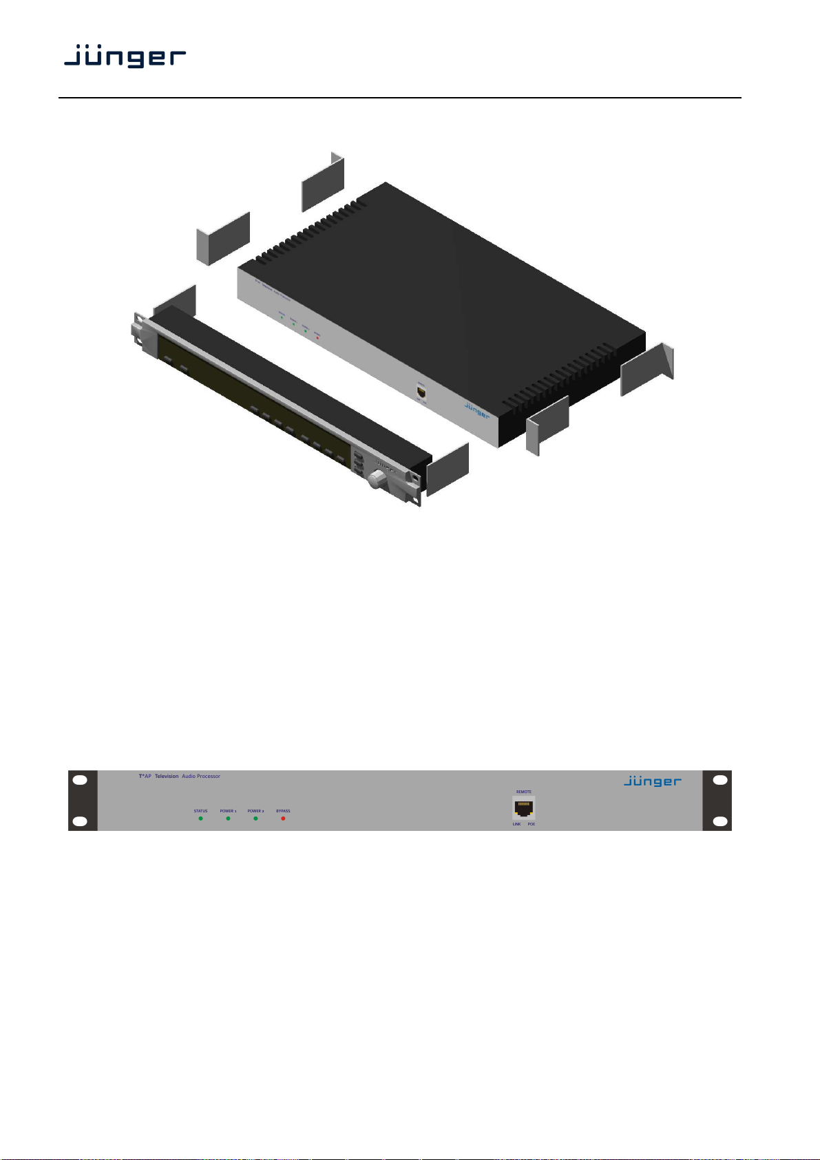
The T*AP consists of a Base Unit that carries all relevant connectors and a detachable
X*AP Remote Panel both in 19" 1RU format.
The X*AP Remote Panel is powered by POE (Power Over Ethernet) and designed to control multiple
Base Units one at a time.
For a stand alone installation the X*AP Remote Panel may be attached to a dedicated Base Unit by
brackets.
In this case we highly recommend to support the chassis by additional brackets screwed to the rear as shown
above or by metal angles supporting the device from the bottom.
Base Unit front panel view
The front panel of the Base Unit shows 4 status LEDs :
STATUS general representation of the device status. It is a sum display of all relevant
Power 1 status of power supply # 1
Power 2 status of power supply # 2
BYPASS shows if one of the audio processing parts of the T*AP is put into bypass mode
status information
4
Page 9

T*AP
Base Unit rear view
For fail safe operation the Base Unit provides two independent power supplies. These power supplies
operate in load balance. The status of both PS are displayed on the Base Unit front panel as well as on the
X*AP Remote Panel.
STATUS LED shows the status of the device controller
INIT pressing the INIT button briefly will warm start the device controller.
Holding down the button until the STATUS LED flashes 3 times will initialize the
LAN RJ45 socket for Ethernet connection to a LAN
USB USB 2.0 type B socket to connect the built in USB >> serial converter with an
ISO-PWR LED lights up if the isolated 5V power supply for GPI /O application is turned on
GPI 25pin Sub-D female connector to interface with the 8 optical isolated general
GPO 25pin Sub-D female connector to interface with the 8 switch over relay general
Interface 1 slot to mount one of the optional interface boards (SDI, AES, analog)
Interface 2 slot to mount one of the optional interface boards (SDI, AES, analog)
METADATA IN 9pin Sub-D female connector to receive and send Dolby® serial metadata
METADATA OUT 9pin Sub-D male connector to send Dolby® serial metadata
SYNC IN 75Ohm BNC connector to connect with external sync sources
WCKL-OUT 75Ohm BNC connector to synchronize external devices to the T*AP internal
AES IN 1/2 – 7/8 AES3id inputs
AES OUT 1/2 – 7/8 AES3id outputs
Base Unit to factory default
external PC
purpose inputs
purpose outputs
word clock
5
Page 10
block diagram
T*AP
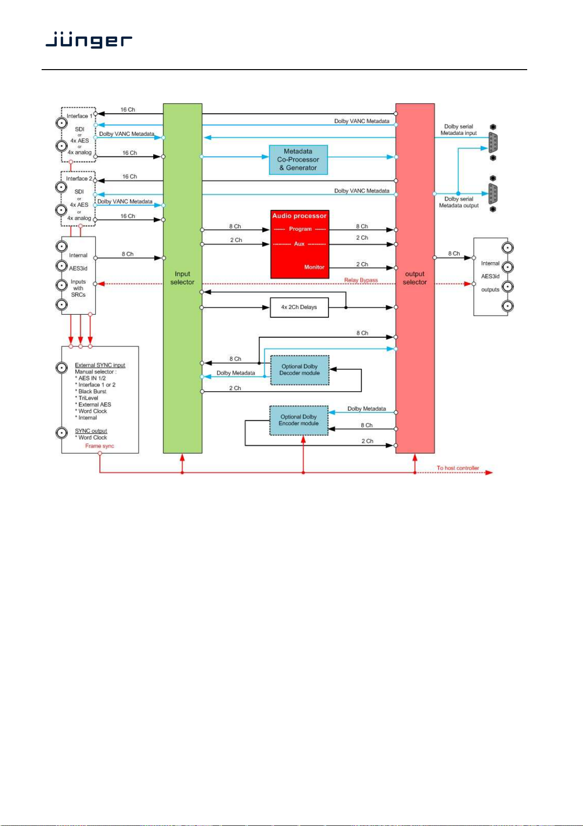
The above schematic shows the principal blocks of the T*AP.
The core of the unit is the 10 channel Audio Processor with 2ch Aux inputs and a 2ch monitor output.
On the motherboard you will find 4x AES3id I/Os which are bridged by relays in case of a power failure.
Two I/O slots which may carry option boards allow for extremely flexible interfacing of the T*AP. I.e. you may
process the audio signals of two independent TV programs.
The unit may also be fitted with Dolby E/D/D+ decoder and encoder. For comprehensive metadata
processing the unit has serial metadata I/O connectors. All metadata functions are centralized in a metadata
Co-processor.
The sync circuit provides all features to integrate the T*AP into digital processing environments. Other
devices may be synchronized by the word clock output of the T*AP.
Beside the option to delay all DSP outputs, the T*AP has 4x 2Ch delay lines that may be routed into any
signal path of the device.
6
Page 11
T*AP
audio processing blocks
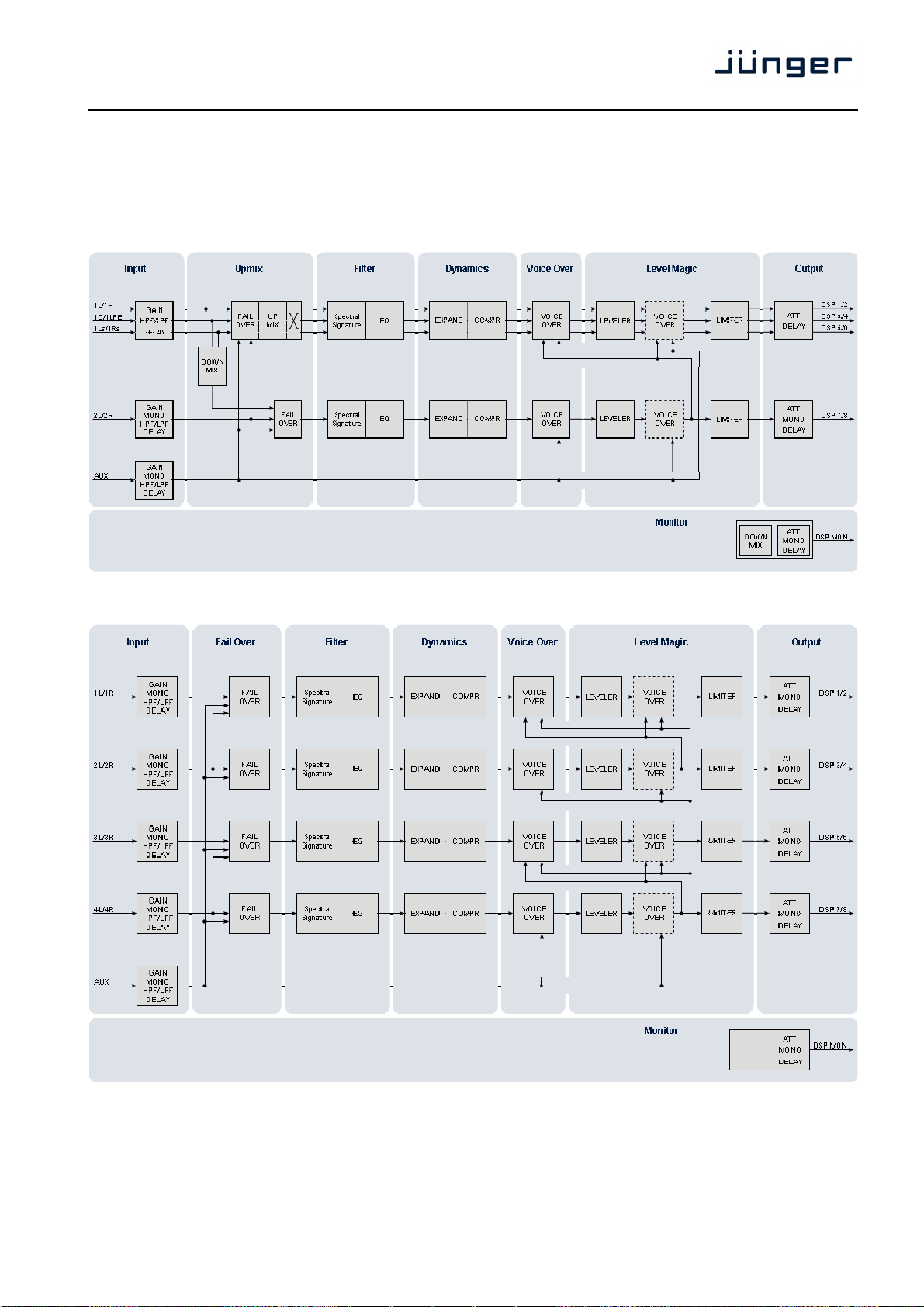
Speaking in D-E terminology, the T*AP may be configured as a surround sound processor with additional
stereo program processing (5.1 + 2) or as a four times stereo processor (4 x 2).
Audio processor block diagram 5.1 + 2 program configuration :
Audio processing block diagram 4 x 2 program configuration :
Important Note! In a 4 x 2 configuration, the processing links between stereo channels may be disabled via
the respective function block, to perform full or partial mono processing if required. You must keep in mind
that such a configuration is still treated as 4 programs if it comes to program related setups and information
such like the Dolby Metadata.
7
Page 12

T*AP
control concept
The communication between the X*AP Remote Panel, the Base Unit, setup and operating tools, is based on
TCP/IP over Ethernet.
The setup GUI utilizes web technology. At the time of editing this manual the functionality of the web GUI is
developed for Firefox 15.1.
The setup GUI will be completed by several application programs running under MS Windows® XP, W7
like the JA Application Manager.
An SNMP agent is also available on the device and may be explored by a monitoring system.
Junger highly recommends using the l-s-b Ember+ protocol which is widely distributed in the European
broadcast industry where the user community is increasing rapidly world wide. By the way, the X*AP Remote
Panel and the Base Unit "talk" Ember natively. For backwards compatibility the T*AP supports both the
Ember (on TCP port 9999) and Ember+ (on TCP port 9000).
operating concept
Further below you will see that the setup GUI for the device is grouped into several parameter areas.
One can reach the parameters via a 3 tier navigation by tabs which may have sub tabs and the sub tabs may
have page embedded soft buttons for groups of parameters.
Each parameter area has a set of presets. The presets can be recalled at any time during operation, either by
manual intervention, automatically by the internal event manager or by external authorities.
For all relevant settings an ON AIR and a PRESET part exists. I.e. you may either edit the parameters
ON AIR or offline for the respective part of the T*AP. You may recall such presets at any time manually, or
automatically.
The presets of the T*AP are persistent by nature. You are working directly on the preset memory, i.e. you
must not worry about storing such presets. The T*AP does it for you.
event concept
With the T*AP you have a sophisticated event management system on hand.
Events are bound to Trigger which may be nested and are defined by the logical combination
(AND, OR, XOR) of two random trigger sources. Such a trigger source may be device status information
(e.g. sync lost), GPIs, network commands, hotkeys of the X*AP Remote Panel, status (true or false) of
parameters.
The pre defined trigger may ignite events which will recall presets from the several function blocks
of the T*AP :
* Preset Events for System, Interfaces, Routing, Dolby Processing, Audio Processing
* Action Events for GPOs, Loudness Measurement
* Bypass Events for pre configured bypass scenarios
8
Page 13
T*AP
getting started – basic X*AP Remote Panel operation
The communication interface of the T*AP is based on TCP/IP over Ethernet. The X*AP Remote Panel as well
as the Base Unit must have unique IP addresses in order to "talk" to each other as well as to other devices
within the Local Area Network. An X*AP Remote Panel may for now control up to 4 Base Units, one at a time.
If the X*AP Remote Panel is attached mechanically to a Base Unit it should be connected via the Ethernet
socket on the front panel of the Base Unit. If the X*AP Remote Panel is detached from the Base Unit, one
may use the CAT5 cabling of a facility or the OB-Van to connect it to the distant Base Units front socket in
order to get power. If it must be connected via a router of the network, this router must have a POE (Power
Over Ethernet) port. If this is not the case, you must use a wall plug POE power supply.
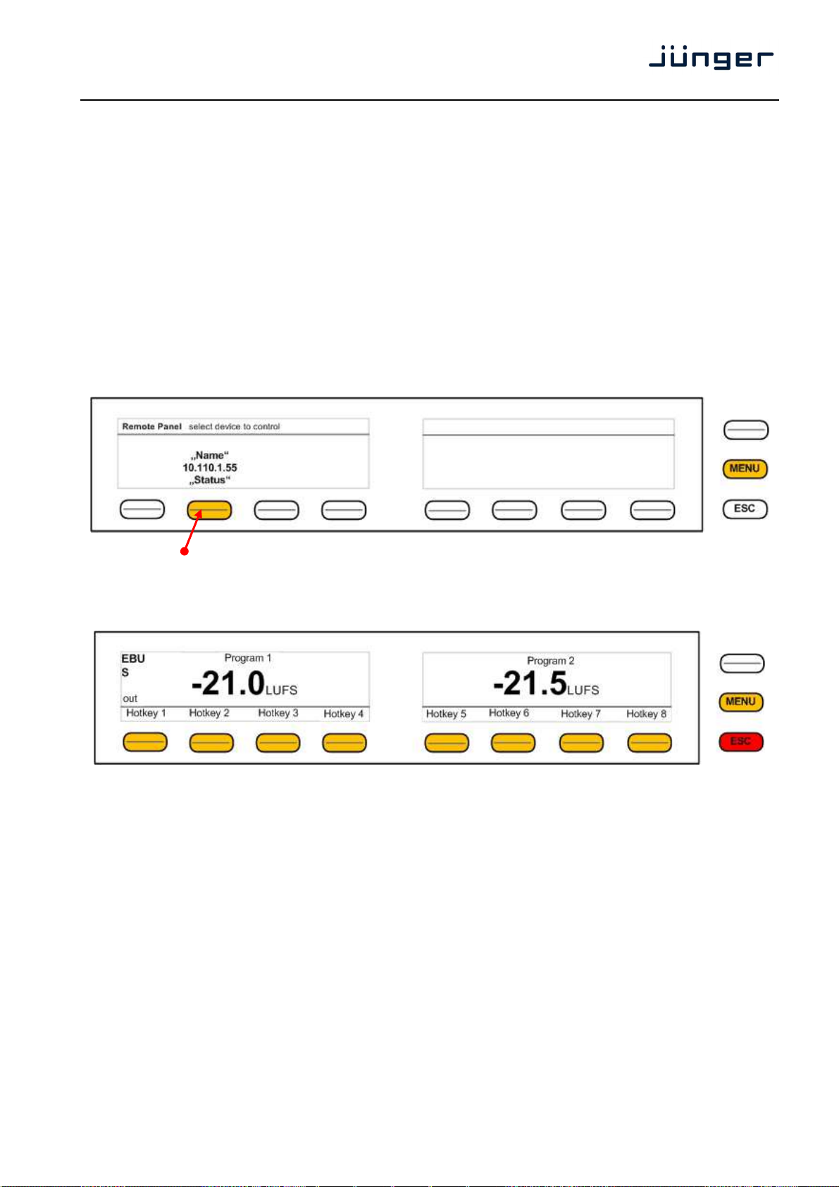
After power up and booting, the X*AP Remote Panel shows the T*AP Base Units which are "attached" to it.
The display shows the respective device "Name", the IP address and the connect "Status".
Options are "connect", "can't connect" and "unknown device". In case of "connect" you may press one of the
highlighted buttons.
If you press the <F-Key> the X*AP Remote Panel will connect with that Base Unit.
(The above example has just one T*AP Base Unit attached for remote control ). Now the X*AP Remote
Panel will gather all necessary information from that Base Unit (may take a few seconds) and open up the
main operating display :
Because this is the main operating display, the <ESC> button light red to indicate that the power up display is
above the main display. Pressing <ESC> returns you back to the device selection.
getting started – IP setup in general
The process of installing a T*AP into an IP network is as follows :
1. Ask the system service people for two unique IP addresses of the network,
netmask and gateway address
2. Assign the Base Unit an IP address
3. Assign the X*AP Remote Panel an IP address
4. Attach the Base Unit to the X*AP Remote Panel
You have 2 choices to assign the Base Unit an IP address :
* From the serial console interface
* Via Web browser
! Important Note: If you are not familiar with setting up devices for IP communication, we highly
recommend you consult your system service or IT department to assist you.
9
Page 14
T*AP
getting started – IP setup of the Base Unit – via console interface
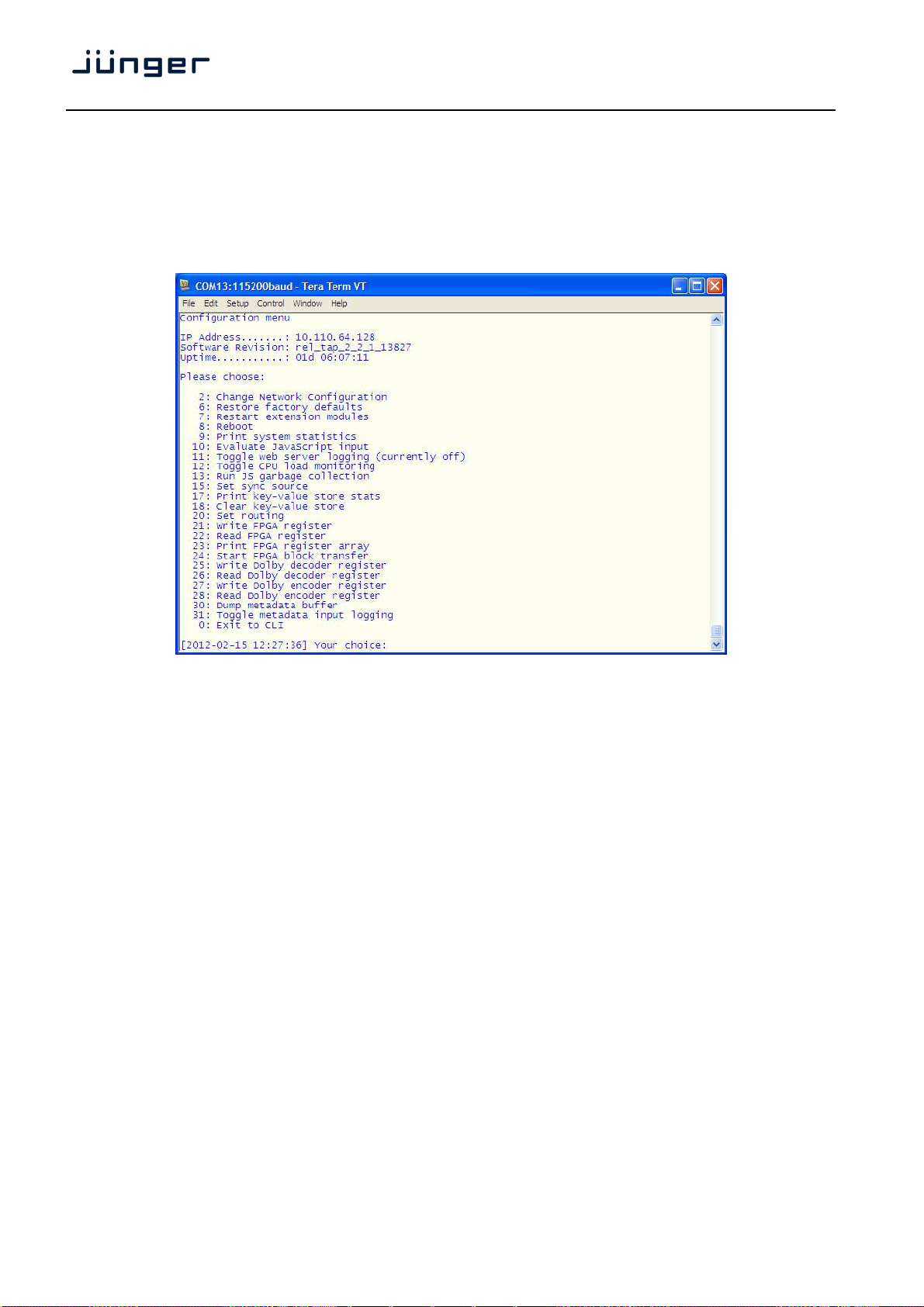
The tool to change the IP configuration of any Base Unit will be reached via the console interface. You must
connect the Base Unit with the PC via an USB A to B cable. This will install the driver for the built in USB to
serial converter. Now you can open a terminal program. Here you must select the virtual COM port
assigned by the OS. The communication parameters are :
115200kBaud, 8, N, 1 no hand shake. Pressing <ENTER> will open the console menu :
Go for item 2 and press <ENTER> :
"Your choice: 2"
"Current network configuration
IP Address : 10.110.24.128
Netmask ... : 255.255.0.0
Gateway ... : 10.110.0.1
You must enter the IP address and the netmask.
Enter new IP address, press ENTER to cancel : "192.168.176.78" <Enter>
Enter new netmask, press ENTER to cancel : "255.255.255.0" <Enter>
Important Note! The gateway entry is optional but you must take care that the gateway address matches the
network mask related to the device IP address!
If you re not sure simply enter 0.0.0.0.
Enter new gateway, press ENTER to configure without gateway : "0.0.0.0" <Enter>
Network configuration has been changed. Please reboot the device
To activate the new settings.
Select item 8 and press <ENTER> :
Do you want to reboot the device ?
Press small "y" :
Do you want to reboot the device ? y
Press <ENTER>
Rebooting the device ……..
After reboot has finished the new IP configuration is active.
10
Page 15
T*AP
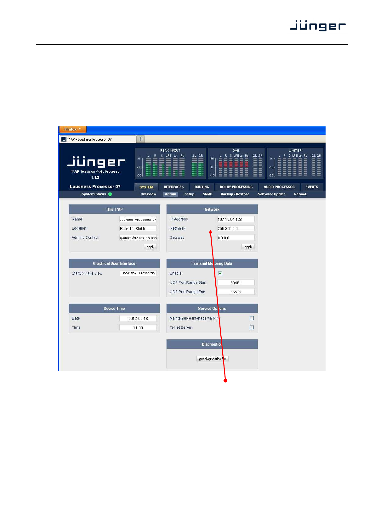
getting started – IP setup of the Base Unit – via web browser
* Read the default IP address printed on a label above the RJ45 Ethernet connector.
* Set up network parameters of the PC which meet the default IP address of the Base Unit
(net mask = 255.255.0.0).
* Connect the Base Unit with the PC either by an Ethernet cross over cable or by a switch.
* Open a browser and type IP address of the Base Unit into the URL field and press <ENTER>.
This will open the AUDIO PROCESSOR tab sheet of the GUI.
* Click on <SYSTEM> and the "Admin" tab will open automatically :
Enter the desired network configuration and press <apply>
Afterwards you must reboot the Base Unit in order to activate the new IP configuration.
Regarding Gateway address see above.
Important Note! After reboot neither the web browser nor the X*AP Remote Panel may be able to
communicate with the Base Unit. You must key in the new IP address in the URL field and change
the X*AP Remote Panel settings to attach this device again.
11
Page 16
T*AP
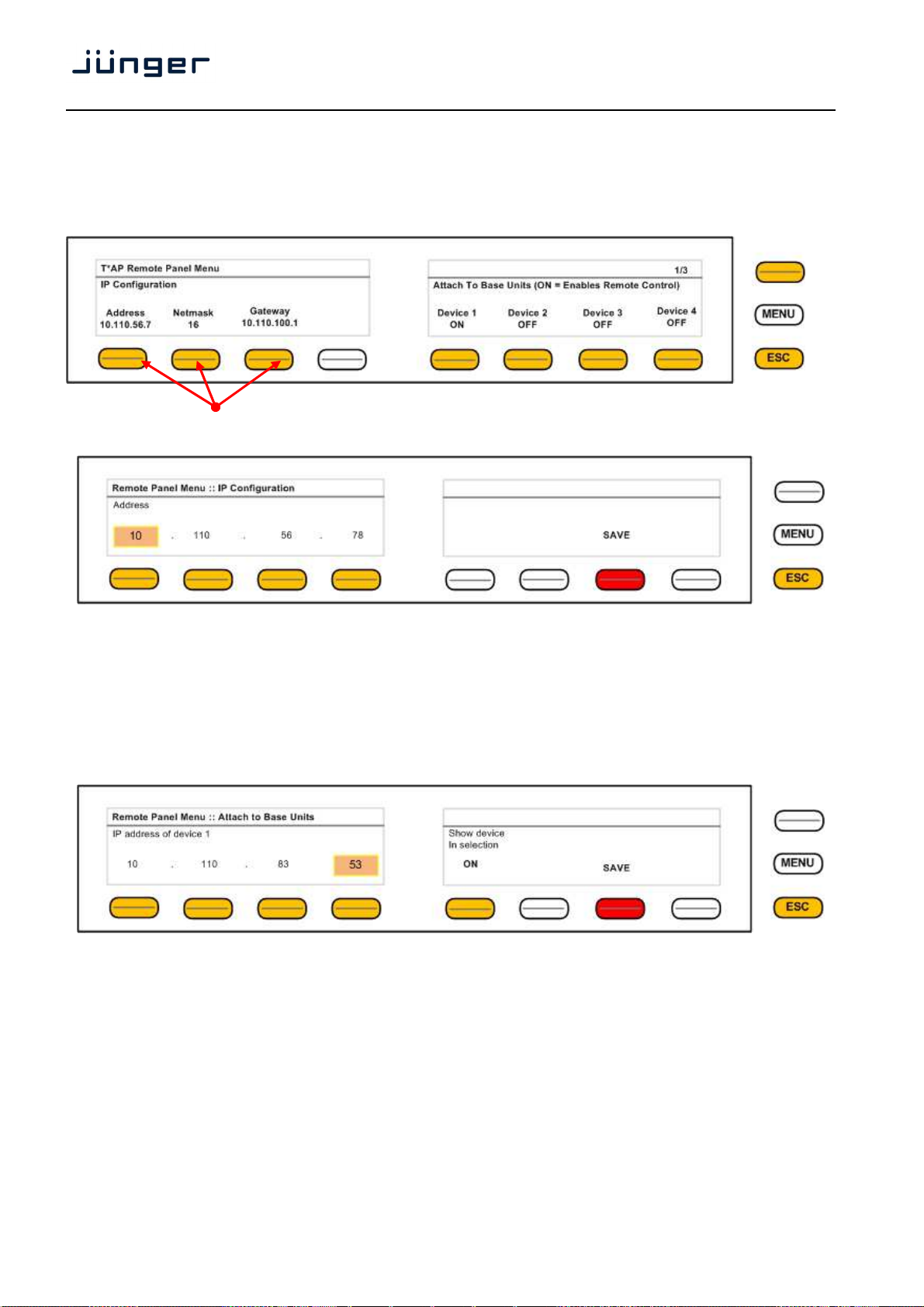
getting started – IP setup of the X*AP Remote Panel
By pressing the <MENU> button after power up or by pressing the red <ESC> button from the main display,
you will enter the "T*AP X*AP Remote Panel Menu" page 1/3 to set up the IP configuration of the X*AP
Remote Panel and to attach up to 4 devices to this X*AP Remote Panel :
You may press the relevant <F-Keys> and separate windows will appear for comfortable set up.
Here an example for the address field :
You must press one of the relevant <F-Keys> and that field will be highlighted as well as the Rotary Encoder.
Now you can change the value by turning the knob. When the setting of all fields is finished, you must press
<SAVE>. The display will return to the initial "T*AP X*AP Remote Panel Menu" page 1/3.
getting started – attach a Base Unit to a X*AP Remote Panel
You must press one of the "Device x" <F-Keys> and a different window will open :
Same procedure: Set up the IP address of the Base Unit you are about to attach.
You must turn "Show device in selection" to ON in order to reach the device via the initial display later on.
Pressing <SAVE> will return to the "T*AP X*AP Remote Panel Menu" page 1/3.
12
Page 17
T*AP
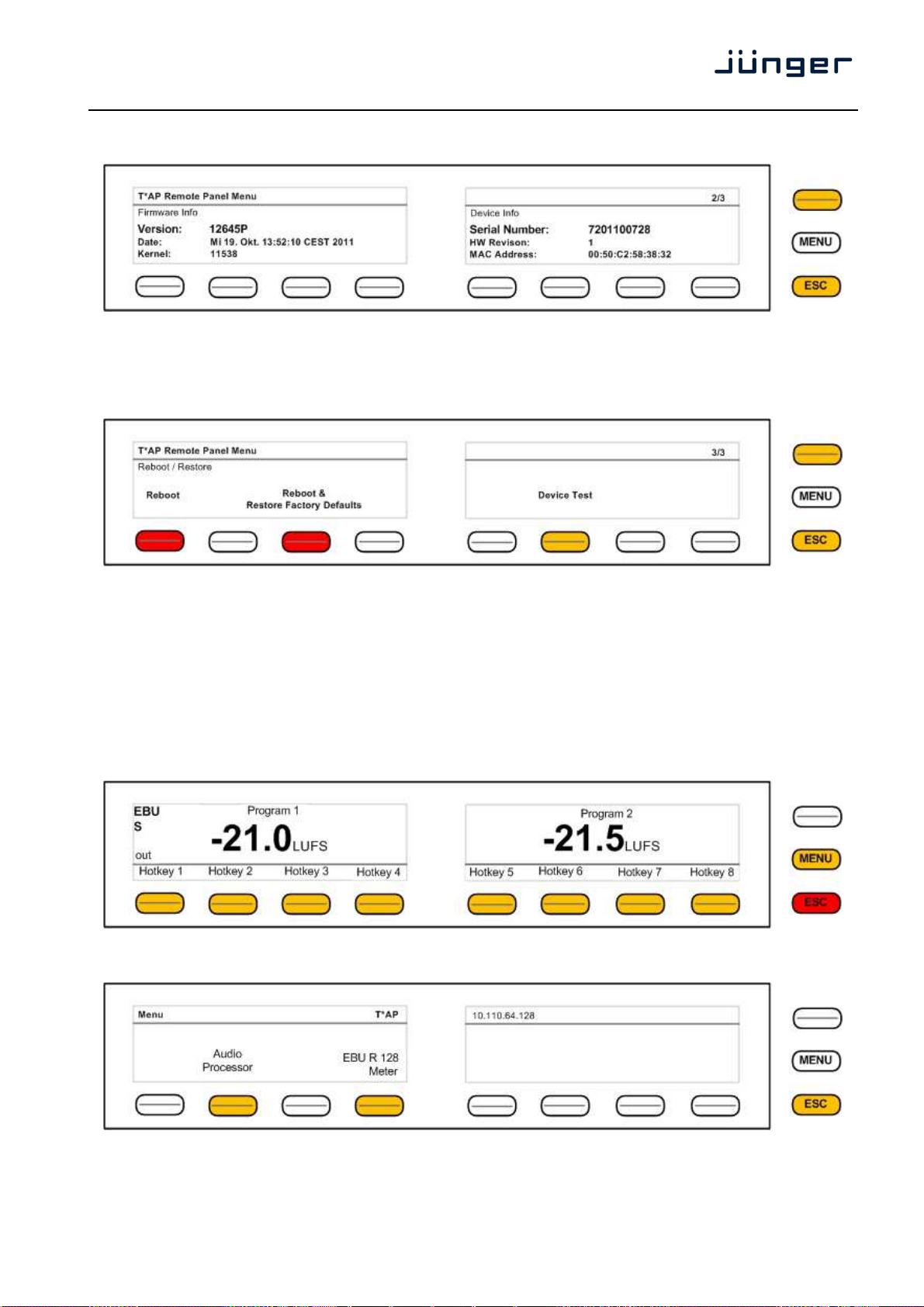
getting started – X*AP Remote Panel menu page 2/3
This page shows static information regarding firmware versions and device infos.
getting started – X*AP Remote Panel menu page 3/3
– firmware display
– reboot, restore factory default, device test
Page 3 allows for reboot, restoring of factory defaults and function test of the X*AP Remote Panel LEDs,
buttons and the rotary knob. Pressing the Device Test button opens up further menus to test the respective
items.
operating - menu structure of the X*AP Remote Panel
Power up display – may show up to 4 Base Units enabled for remote control for this X*AP Remote Panel.
Pressing these buttons connects with the respective Base Unit.
After gathering all Base Unit settings the Main Display opens up :
When pressing the <MENU> button, the main operating menu opens up:
13
Page 18
T*AP
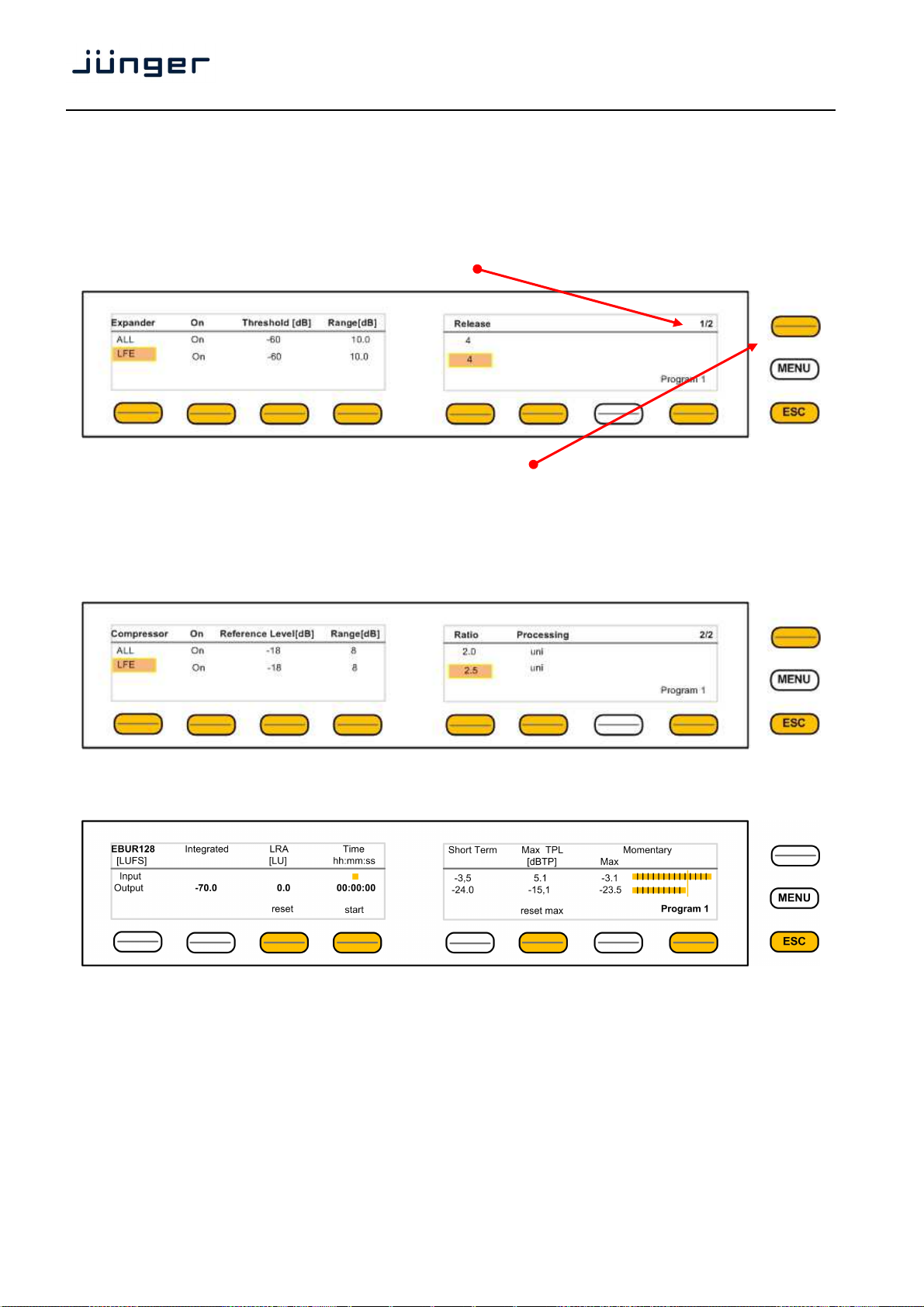
operating – menu structure of the X*AP Remote Panel - principle of operation
If you are in a specific parameter menu the display structure may change due to the program configuration of
the T*AP. Below is an example for setting the parameters for the Dynamics while the T*AP is in
5.1 + 2 program configuration and operates in ITU mode. In this case you have two parameter sets for the
first program: ALL and LFE (if the LFE is not linked).
Since the Dynamics have two subsections: Expander and Compressor, this menu has two pages,
indicated by the number in the top right hand corner :
You may switch between both pages with the <page> button
<Hotkey 1> toggles between the two parameter sets ALL / LFE. The parameter set under control is
highlighted. If for example you now press <Hotkey 5>, the Release setting for the LFE will be enabled and
the Rotary Encoder is also illuminated. You may now change the Ratio by turning the knob.
<Hotkey 8> toggles between Program 1 (5.1) and Program 2 (1x2).
Next page shows the Compressor parameters
Here another example for <EBU Meter>
In this case the <Hotkeys> will control the program based loudness measurement process defined by
EBUR128. The display represents the measurements of Integrated- / Short Term- and MomentaryLoudness as well as the LRA (Loudness Range) [LU] and Max TPL [dBTP],
the Maximum True Peak level.
The measure for the EBU Meter display is [LUFS] (Loudness Units Full Scale) as long as not defined
differently.
For details pls. refer to the EBU-Tech 3341 document.
14
Page 19

T*AP
operating – menu structure of the X*AP Remote Panel – menu tree
Power Up Display
<MENU> opens X*AP Remote Panel IP setup menu.
<Address> setup
<Netmask> setup
<Gateway> setup
< empty >
Device 1 setup IP & ON / OFF
Device 2 setup IP & ON / OFF
Device 3 setup IP & ON / OFF
Device 4 setup IP & ON / OFF
<ESC> back to power up display
After connecting with a Base Unit the Main Display opens up :
Main Display
<ESC> will jump back to power up display
<MENU> opens Operating display:
Hotkey #
1 <Empty>
2 <Audio Processor>
1 <Input>
2 <Upmix> [page 1 - 2]
3 <Equalizer> [page 1 – 5]
4 <Spectral Signature>
5 <Dynamics> [page 1 - 2]
6 <Level Magic> [page 1 - 3]
7 <Output>
8 <Monitor> [page 1 - 2]
<ESC> back to Menu
3 <Empty>
4 <EBU Meter>
1 <empty>
2 <empty>
3 <reset>
4 <pause/continue>
5 <empty>
6 <reset max>
7 <empty>
8 <Program_x>
<ESC> back to Menu
5 <empty>
6 <empty>
7 <empty>
8 <empty>
<ESC> back to Main display
15
Page 20
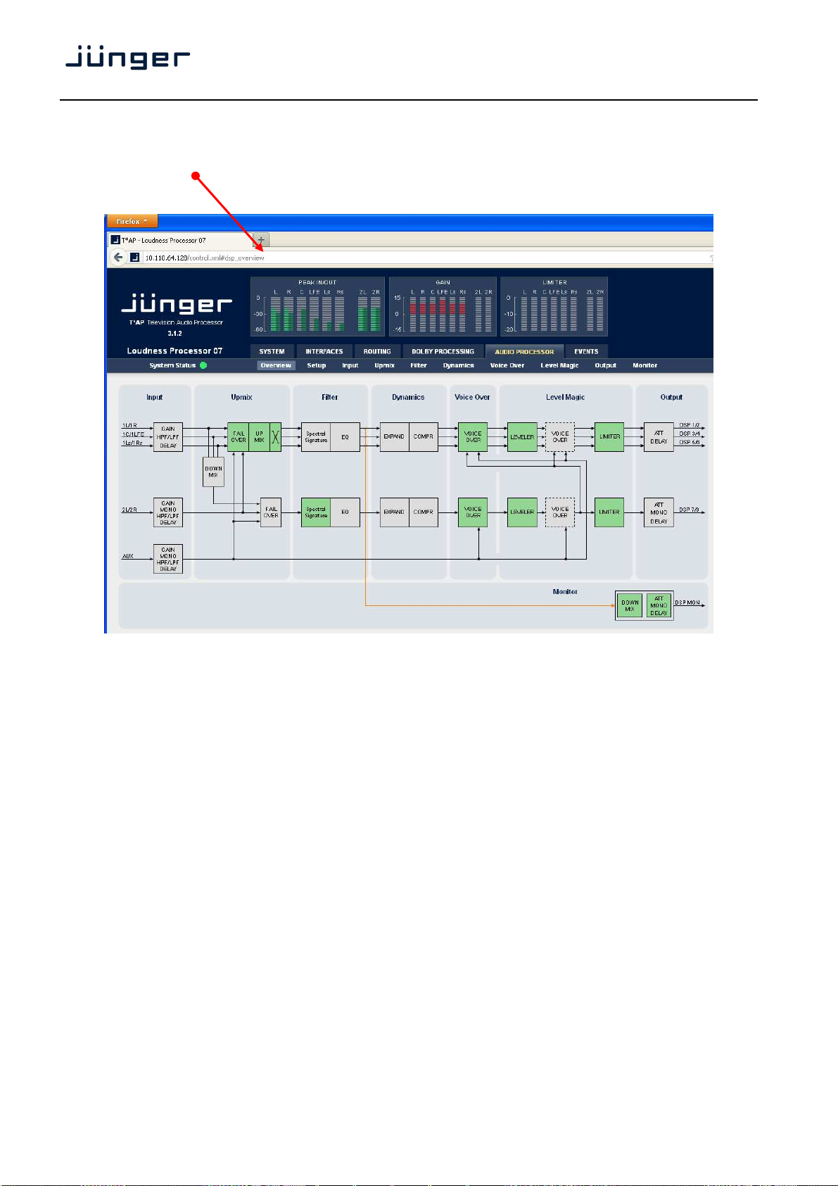
setup GUI – connecting with the Base Unit – AUDIO PROCESSOR > Overview
You must open a browser and enter the IP address of the Base Unit
into the URL field and press <Enter>. The browser will fetch the necessary information and opens the
entrance page :
T*AP
It is the AUDIO PROCESSOR pane with its sub pane Overview.
On the following pages we will go through the various panes of the setup GUI.
Firstly you must set up basic things such as program configuration, give the programs meaningful names and
set the synchronization source. You may also give the device a name, tell it its location and define an
administrative contact which may be used by monitoring systems of your house (e.g. via SNMP).
These settings you will find under the SYSTEM link.
16
Page 21
T*AP
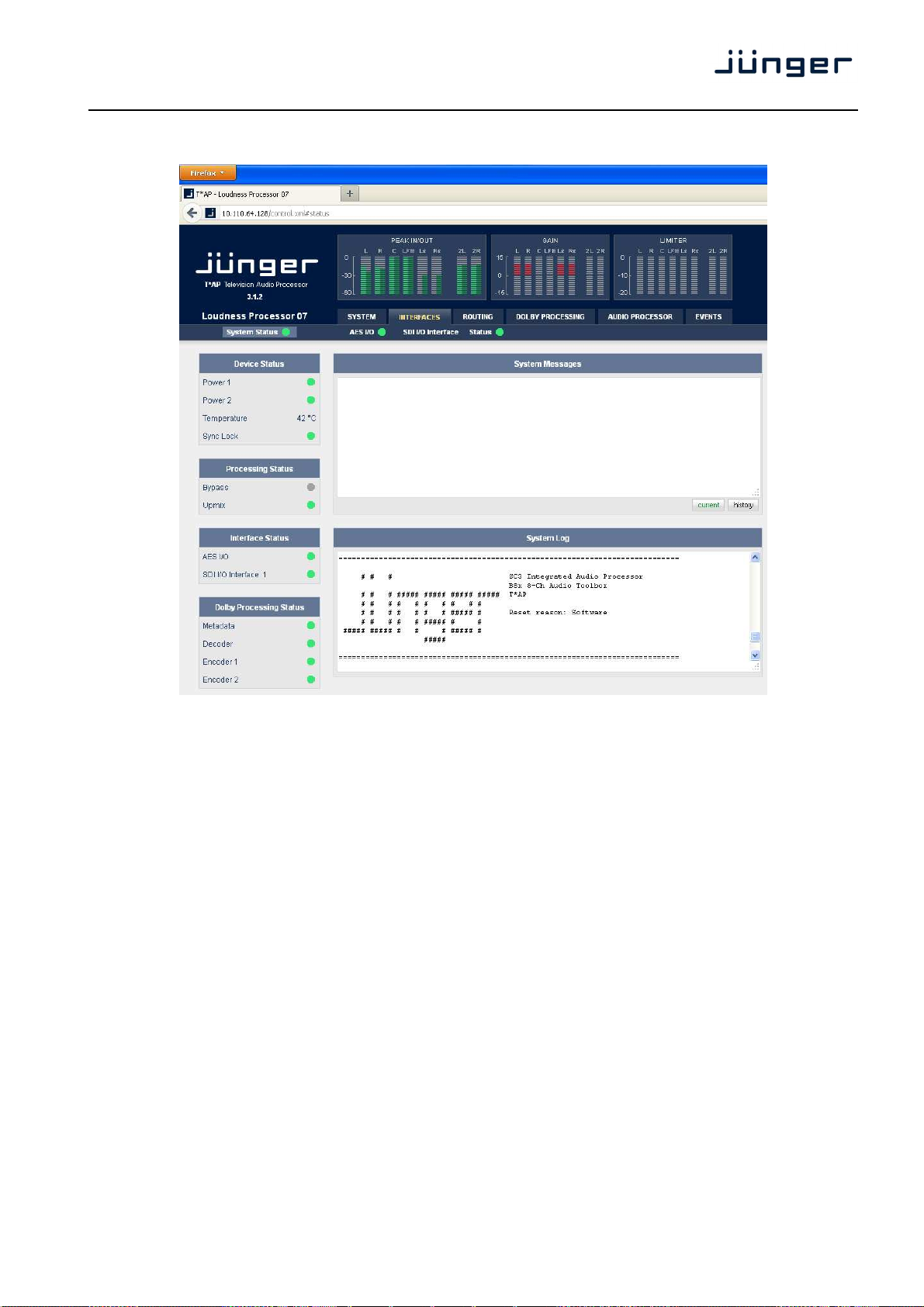
setup GUI – SYSTEM – System Status
The System Status page provides a top level view of the various status information available for the device.
Device Status provides the hardware status of the Base Unit
Power 1 status of the first power supply (left hand side from rear)
Power 2 status of second power supply (right hand side from rear)
Temperature measured on the surface of the main PCB
Sync Lock turns red if the external sync source is removed or unstable
Processing Status
Bypass turns red if Bypass is activated
Upmix turns green if Upmix is activated
Interface Status
AES I/O turns red if an AES input that is internally in use (i.e you have routed it to
an input of a function block) has detected an error
SDI I/O Interface turns red if the SDI input is not locked (no or bad SDI signal)
Dolby Processing Status
Metadata turns red if Metadata are not valid
Decoder turns red if the input signal is not Dolby encoded (PCM or corrupted)
Encoder 1 status of the first encoder (if optional CAT561 is installed)
status of the D-E encoder (if optional CAT569 is installed)
Encoder 2 status of the second encoder (if optional CAT561 is installed)
17
Page 22

setup GUI – SYSTEM – Overview
T*AP
The graphical overview shows the main building blocks of the device including the options installed such as
Dolby OEM modules or interface modules.
You may click into the boxes and the respective page will open. The navigation is based on URLs so you may
use the <Back> navigation button of the browser to return to this page.
setup GUI – SYSTEM – Admin
18
Page 23

T*AP
This T*AP input fields for information utilized by higher level services.
Name give the device a meaningful name that may be used by name services
Location the place where the T*AP is located.
Admin / Contact e-mail address of a person in charge.
Graphical User Interface defines the appearance of the parameter panes regarding preset editor
Device Time allows you to set the device clock. At the factory it is set to
Date if you click into the Date input field,
Time if you click into the Time
Network IP address setup, see above:
getting started – IP setup of the Base Unit – via web browser
IP Address
Netmask
Gateway
Transmit Metering Data metering data will be streamed via UDP protocol. In order to receive such
Enable enables UDP port range use by the device for transferring meter data
UDP Port Range Start lowest port number.
UDP Port Range End highest port number.
Service Options
Maintenance Interface
via RPC for in house use to enable communication with factory tools.
Telnet Server enables a telnet server to connect the consol interface via IP (port 21).
Diagnostics
get diagnostics file pressing this soft button will start the assembly of a diagnostics file.
and SNMP management.
and on air parameter visibility (see below – for preset concept).
UTC (Coordinated Universal Time).
a comfortable calendar tool will pop up :
input field, you will be able to
set the device time
data by external applications you must define ports (port range) for
matching fire wall definitions.
from the Base Unit to the PC where the browser resides.
The file will be presented in XML format for download.
If you experience unexpected behavior of the device you may be asked by
the Junger service team to send such file by e-mail for analysis.
19
Page 24

setup GUI – SYSTEM – Setup
T*AP
T*AP Program Configuration here you may select between 5.1 + 2 and 4 x 2. This will
Program Labels each of the individual programs (two in 5.1 +2 and four in 4 x 2 has
T*AP Synchronization Source with this pull down you may select between
setup GUI – SYSTEM - the preset concept in detail
The example above shows the preset concept of the T*AP. It is the central theme of the device.
For all relevant setting of the device one set of ON AIR parameters and 20 sets of PRESETS are available
If you want to load parameters from a preset or save parameters from the ON AIR area to a preset,
you must first select a preset number at the bottom of the ON AIR page.
You must press to open the pull down list to select the desired preset.
Pressing will execute it. When you press , you will be asked in a pop up :
automatically configure all audio processing parts processors
a name that will be used as a reference for the display of
parameters and its setup.
the available sync sources :
Internal 48kHz, External AES, Input AES 1/2, External WCL,
Interface x (if an option board is installed Black Burst or TriLevel).
to overwrite the selected preset and to give it a (new) name.
acts as a clip board for the parameters of individual presets,
while will allow you to store / recall the set of 20 presets to / from the PC file system.
Important note! The presets of the T*AP are persistent by nature. You are working directly on the preset
memory, i.e. you must not worry about storing such presets. The T*AP does it for you.
20
Page 25

T*AP
setup GUI – SYSTEM – SNMP
This pane is meant for basic settings of the SNMP Agent of the device. If you are not familiar with the use of
SNMP protocol for system monitoring you should not enable the SNMP agent.
setup GUI – SYSTEM – Backup / Restore
Here you can backup the complete device and restore parts or all of it .If you press the device
controller will collect all necessary data and assemble it to an XML file. Finally you will get a pop up message:
You must select :
<Save File>.
After pressing <OK>, the
system file dialog opens :
Select a folder
and alter that default file name
if needed.
21
Page 26

set up GUI – SYSTEM – Software Update
The files to update the TAP will be available in ZIP format. You must unpack them to your PC in order to
access them for the update procedure.
You will find an image file for the TAP core system in the format : "rel_tap_x_y_z.img"
as well as update files for components, like the optional interface boards in the format :
"rsdi150_v47.sdi" or for Dolby CAT (OEM) modules or for the X*AP Remote Panel.
T*AP
To update the Base Unit, you must <Browse …> for the respective
Firmware File(which you have unzipped before) and press .
After finishing the procedure the device will reboot.
You may also update the firmware of an SDI board installed in one of the two interface
slots (or both). The example above shows one SDI I-O board installed into
interface 1 slot. You must select the appropriate file from the firmware update bundle (ZIP file)
and press afterwards.
browser based set up – firmware update of the X*AP Remote Panel
You must open a browser and enter the IP address of the X*AP Remote Panel into the URL field :
You must select the respective
file and press :
After finishing the procedure
the X*AP Remote Panel will
reboot and you must manually
reconnect the Base Unit you are
about to control.
22
Page 27

T*AP
set up GUI – INTERFACES – AES I/O
Input Status each AES input has a status detection that may show :
PCM, Non PCM (e.g. Dolby encoded signal) or
Fail (no carrier, unlock, cranky [too much jitter]).
The non PCM status will be retrieved from a logical combination of
the Validity flag and the channel status.
If one of the inputs is not assigned by the ROUTING section, its
Input Sample Rate Converter for asynchronous sources it is possible to turn a SRC on per input.
AES Relay Bypass the power fail bypass relays of all 4 I/Os may be activated manually.
It is possible to exclude AES I/Os from the relay bypass circuit.
You must open the cover plate from the Base Unit and locate
They are located close to the 9-pin Dolby
status will not be incorporated into the System Status.
If a SRC is turned on and the input status becomes Non-PCM, the
respective SCR will be turned off automatically in order to maintain
the original data structure of an encoded bit stream like Dolby E.
the 4 jumpers shown in the schematic below.
metadata OUT connector at the rear.
You must remove the jumper to exclude the respective AES I/O.
Output Channel Status the channel status can be either
transparent from the input source
of the T*AP or may be overwritten.
The pull down offers these options :
23
Page 28

set up GUI – INTERFACES – SDI I/O interface – De-Embedder
This pane has three more sub panes implemented
set up GUI – INTERFACES – SDI I/O interface – Embedder
T*AP
The De-Embedder has a
16 x 16 matrix to allow for
any combination of audio
signals to be presented to
the T*AP because inside
the T*AP the signal routing
is oriented in pairs. I.e. the
label "SDI 1/2" represents
two audio channels
selected by the matrix.
An additional
Dolby metadata stream
may be de-embdded from
the SDI.
For details see
SMPTE 2020-2 standard.
24
Page 29

T*AP
"DSP 1/2" …. "OFF" signal labels from the T*AP router that shows the origin of the signal pair
Video Delay For compensation of any kind of audio processing delay within the chain of
Generate new SDI If there is the need to replace the structure of the Ancillary Audio
Audio Structure Data Blocks you can clean the whole area and generate a new structure.
SDI Out Grx This check box enables each of the 4 SDI audio groups to be used
Silence Mutes the respective audio channel on the embedder side.
Delay The inputs of the embedder routing matrix can be taken either
from the de-embedder or from the T*AP in any combination. If they are
For signals coming from the T*AP routing an independent delay per
Channel Status Bits For the signals coming from the C8k audio busses, you can decide
Transparent whether the AES Channel Status Bits are taken from their source or if
In this case the Channel Status will be set to:
Important note! If you generate a new AES channel status the Audio Mode will be automatically set to
Non Audio for both channels, if an adjacent pair (1/2, 3/4 …..) carries a Dolby E stream for example.
VANC Metadata the VANC Dolby Metadata embedder allows you to embed a metadata
You can select a line where the metadata must be embedded.
For details see SMPTE 2020 standard.
presented to the embedder.
devices you may use a Video Delay.
Position “0” turns off the delay function.
If the option is checked, there will be no signal available at the group
output as long as no SDI Out Grx is checked.
individually by the embedder. If it is not checked and
“Generate new SDI Audio Structure” is not enabled, the audio data from
the input will travel untouched from the SDI input to the output.
taken from the de-embedder and a Video Delay is introduced, the time of
that Video Delay will be automatically compensated for those signals.
single channel may be used.
you want to generate new ones.
Format : Professional
Audio Mode : Audio / Non Audio
Emphasis : None
Freq. Mode : Locked
Sample Freq. : 48kHz
Channel Mode : Not Indicated
User Bits : None
Auxiliary Bits : 24Bit
Audio Word Length : Not indicated
stream. You may assign the stream an independent SDID.
25
Page 30

set up GUI – INTERFACES – SDI I/O interface – Setup
T*AP
Relay Bypass will deactivate the Bypass Relay. It provides a shortcut from
SDI-IN to SDI-OUT1 and disconnects the de-embedder
from the SDI input. This relay also serves as a fail bypass if the power is
off. This feature maintains the SDI signal for downstream equipment.
SDI Bypass will pass the embedded audio data from the de-embedder
to the embedder 1:1. This function preserves the original
Ancillary Data structure.
Stream Select (3G-B) a 3G-SDI signal may have two HD substreams (e.g. for 3-D TV),
AKN as 3G-B standard. The radio buttons select between
stream 1 or 2 for embedded audio. See SMPTE 425M for details.
Generator enabled The video generator may be enabled here. The video format it generates
depends on the selection below.
Test Pattern If the Generator is on, it will generate one of the two video test patterns,
either black or 100% color bar.
Video Format If the Automatic mode is selected and the Generator is enabled, it turns
on if the SDI input signal fails. In this case it will generate the same video
format as the previous input signal.
If “Generator enabled” is checked and if you have selected one of the
Video Formats the Generator will be turned on using this format.
Important note! If the generator is on, either in manual or in automatic mode, it operates on an
internal quartz reference. It is not possible to genlock it to an external reference or to the SDI input.
26
Page 31

T*AP
set up GUI – INTERFACES – (SDI I/O Interface) Status
This pan shows the status of the SDI interface (if one is installed) :
Video Standard display of the video standard detected by the SDI input.
SDI Bypass turns yellow if the SDI bypass function is activated.
Relay Bypass turns yellow if the power fail relay is deactivated manually.
Test Generator Active turns yellow if the Generator is turned on.
Video Delay Enabled turns green if the video delay is activated.
VANC Metadata turns green if Dolby metadata is present in the input SDI stream.
De-Embedder
VANC Metadata turns green if VANC embedder is enabled
Embedder
De-Embedder Audio Status is grey if no audio is present
turns green if PCM audio is embedded
turns yellow if a non audio signal is present, an additional label shows
the kind of signal if it is possible to gather the information.
De-Embedder VANC shows which SDID was found and gives the operator an indication
Metadata which audio signals are related to that SDID.
ARIB B39 meta information standard
Data Available turns green if ARIB B-39 meta information are detected
Block Error turns red if an error has been detected
See SMPTE 2020 for details.
Audio Mode see ARIB Japanese standard "Structure of Inter-Stationary Control
Data Conveyed by Ancillary Data Packets"
http://www.arib.or.jp/english/html/overview/doc/2-STD-B39v1_2.pdf
27
Page 32

setup GUI – ROUTING
This is the core of the T*AP because it defines the audio signal flow inside the machine :
T*AP
Each functional block of the device has an input- and an output-label. The output-labels are pre-defined,
while the label of an input must be selected by the administrator in order to route the signals.
Additional blue labels give an indication of the type of signal that is expected by the respective function block
input (e.g. 1L/1R for the DSP). The labels depend on the Program Configuration.
The above screen shot shows an example configuration :
DSP the de-embedder outputs [SDI 1/2 to 7/8] are connected to the
DSP 1/2 [1L/1R], 3/4 [1C/1LFE], 5/6 [1Ls/1Rs], 7/8 [2L/2R] inputs.
After processing by the DSP, these signals will leave it at the outputs
DSP 1/2 to 7/8.
Dolby Digital Encoder an optional Dolby Digital encoder receives DSP 1/2 to 5/6 as an input,
while the 2nd encoder has DSP 7/8 assigned. After encoding the signals
appear at ENC 1 and ENC 2 outputs.
AES the first three outputs AES 1/2 to AES 3/4 are connected with
DSP 1/2 to 5/6 (e.g. for monitoring purposes), while AES 7/8 is
connected to the delay output DELAY 1/2.
Delay a signal pair from the AES 1/2 input will be delayed
by 85ms.
Dolby Decoder an external signal from the 2nd AES input AES 3/4 will be decoded.
When the signal is present, the decoder reads the program
configurations and sets the labels [1L/R, 1C/LFE, 1Ls/Rs] accordingly
at the decoder outputs DEC 1/2, 3/4, 5/6.
Interface 1 DSP 1/2 … DSP 5/6 are connected with the embedder input
EMB 1/2 … EMB 5/6 while encoder output ENC 1 is connected with the
embedder input EMB 7/8. Where these signals will be embedded must
be defined on the respective setup pane :
INTERFACES > SDI I/O Interface > Embedder.
28
Page 33

T*AP
setup GUI – DOLBY PROCESSING
The Dolby® metadata system is too complex to describe it in a product manual like this.
We recommend to those who are not familiar with it, to study the many publications from Dolby® Inc.
which you will probably find here (we can't guarantee that the link is active forever) :
http://www.dolby.com/gb/en/professional/technology/landing.html
But so much for the beginning: The system is designed to squeeze multiple audio signals into standard
2 channel transmission / recording lines. The codecs used for this purpose are intellectual property of
Dolby® Labs. Inc. Additional metadata has been implemented to control the customer experience at home
when listening through TV set top boxes, DVD players, gaming machines, mobile devices.
Dolby distinguishes between consumer and professional metadata. While consumer meta data will travel to
the consumer equipment, the professional metadata is used for the setup of encoders.
The appearance of the following pages depends on the number and type of Dolby decoders / encoders
installed. These modules are an option which may be ordered with the T*AP or later on for field installation.
setup GUI – DOLBY PROCESSING – Metadata – Routing
The center of the T*AP Dolby processing is the built in Metadata processor. It can be the point of origin of
metadata but it may also modify existing metadata from an available source :
The metadata system of the T*AP has three
paths. An independent monitor will allow for
the evaluation of an independent metadata
set, selected by its Source drop down box.
The Metadata Processor in the middle may
take it from an available Source, may
manipulate it in the Follow Input section and
present it to the router for further distribution
at the Output.
The Metadata Source Status
The soft LED turns red If no metadata is
present or the metadata is corrupted.
It turns green and the word OK will be
displayed if a RDD 6 compliant metadata
stream is detected.
It turns yellow and the word CONSUMER
will be displayed to indicate that only a
metadata subset is provided if an AC3 or
similar (D-D+) signal is decoded.
At the bottom right hand side you see the metadata output router. Here you may decide about the Source
that feeds the respective Output.
Source [OFF / D SUB IN / SDI1 VANC / DECODER /
METADATA PROCESSOR]
Important note! The metadata processor generates a full set of SMPTE RDD 6 compliant metadata.
Since the T*AP is designed to handle two (5.1+2) or 4 (4x2) programs all related parameters will be
generated by the processor.
The function blocks Monitor, Follow Input and Delay are not implemented for T*P firmware release 3.1.x
29
Page 34

setup GUI – DOLBY PROCESSING – Metadata - Reversion
This pane defines the metadata sets in case of a loss of metadata from the input :
Beside D-E encoder settings, it will
provide a set of alternative metadata.
This function is not available yet
(release 3.2.x)
setup GUI – DOLBY PROCESSING – Metadata – Program x
This pane displays input meta data and allows for setting of the various metadata separately for each
program :
T*AP
The follow input checkboxes are not active yet (release 3.2.x).
30
Page 35

T*AP
setup GUI – DOLBY PROCESSING – Decoder
Depending on the type of input stream provided to the decoder, this pane shows the incoming stream
parameter and it allows to configure the decoder :
setup GUI – DOLBY PROCESSING – Encoder(s)
The encoder installed in the T*AP may either be a Dolby E encoder or a multifunctional encoder,
that allows for several consumer format encoding :
Dolby Digital plus [D-D+]
Dolby Digital [D-D]
Dolby Pulse [HE-AAC v1 and v2 and AAC]
The multi format encoder has 8 physical PCM audio inputs and may be configured for
3 different operating modes :
A) Two independent encoders stream 1 – 3/2L or 2/0 (D-D+, D-D, AAC, HE-AAC)
(independent audio inputs stream 2 – 2/0 (D-D+, D-D, AAC, HE-AAC)
Independent metadata
B) Two encoders with stream 1 – 3/2L (D-D, D-D+, AAC, HE-AAC)
different formats stream 2 – 3/2L (D-D, D-D+, AAC, HE-AAC)
(but same audio inputs)
C) Two encoders multiplexed stream 1 – (i0 + i1) one output stream (multiplexed
Into one output from two encoded signals. May be used
for ATSC / DVB single PID transport
multiplexes (e.g. for Visually Impaired Audio Description – applications).
Since it is possible to run encoders in different modes (D-D, D-D+, AAC …) the latency of the encoding
process will be different due to the algorithms used. If it is necessary to align the latency of the encoded
outputs, you may turn on "Latency Compensation". In this case a latency of 305ms will be found for
each encoder. This process is performed between encoders, i.e. you must cross check if the check
boxes are enabled for both encoders!
31
Page 36

A) Two independent encoders - configuration for Encoder 1 :
T*AP
B) Two encoders mixed for Dolby Digital plus encoding and for AD (audio description) application :
Encoder 1 Encoder 2
The different channel modes 3/2L [5.1 (surround)] and 2/0 [2 (stereo)], the enabled Mixing Mode (see expert
parameters) and the different stream IDs for both encoders will implicitly set up such stream that can be used
for single PID multiplexing in a DVB or ATSC DTV system.
32
Page 37

T*AP
setup GUI – AUDIO PROCESSOR - Overview
The overview shows the actual signal routing of the audio processor blocks, rendered by the DSPs.
This overview depends on the program configuration of the T*AP.
5.1 + 2 program configuration :
4 x 2 program configuration :
The processing blocks in use, which may be activated from their individual setup panes,
will be indicated in green. Blocks shown in grey are not activated by the user. The location of blocks with
dotted lines within the signal path depends on the block setup.
To navigate through the various processing blocks you may either use the mouse over function or the tabs
provides in the navigation bars below the bar graph displays.
33
Page 38

setup GUI – AUDIO PROCESSOR - Setup
Loudness Control Mode the pull down offers the selection
of these algorithms for the
LevelMagic™ process as well as
for the loudness measurement:
Level the Jünger Audio proprietary
level based algorithm to achieve
the same program level for
different programs.
ITU-BS.1770-1 defined by the ITU and found in
ITU-BS.1770-2 enhanced ITU standard
ATSC standard A/85:2011
EBU R128 defined by EBU-TECH 3341.
Became the de facto standard for
loudness based level control and
metering in TV broadcast.
Processing Bypass will deactivate all predefined processing parameters. Which parameters
are bound to the Processing Bypass function must be defined in the
EVENTS section.
The audio signals still travel through the DSP but they are not
processed, except the compensation for the processing delay of the
Upmix (if Upmix is enabled).
Latency Compensation some processes like Upmix or Spectral Signature have an adjustable
latency to increase the performance of such a processes. This may be
compensate for program paths without latency introduced.
Bit Transparency ON will physically bypass the audio signals related to the labels on the
left hand side. This function preserves the integrity of such signals if
they appear in a signal path (e.g. Dolby encoded streams).
In case of AUTO the channel status will be observed and if Non Audio
is detected bit transparency will be enabled.
The next pages will briefly explain the individual processing blocks.
T*AP
34
Page 39

T*AP
setup GUI – AUDIO PROCESSOR – Input
Link defines the coupling of the control circuits in
order to maintain the listening balance for
correlated signals or to provide a grouping of
the setup parameters for multi channel
signals. To the left is an example that shows
the different link modes. This example
applies in general to all other link settings for
the T*AP.
Depending on the function block and the
control mode (ITU vs. EBU) the number of
possible link settings will differ.
Curves and dots of the same color indicate
the link condition.
Input enables the control of the respective column
Mute will mute all channels controlled by the respective column
Input Gain (dB) sets the gain [-80 … +20]
Input HPF (Hz) high pass filter (6dB/oct) cut off frequency [OFF, 2, 20, 40, 80, 120]
Input LPF (kHz) low pass filter (6dB/oct) cut off frequency [OFF, 15, 20, 22]
Input Delay (ms) [1 … 2000]
35
Page 40

setup GUI – AUDIO PROCESSOR – Upmix & 2ch Fail Over (5.1+2 program configuration)
With firmware version 3.5 Jünger Audio
introduced a new 5.1 upmix algorithm for
upmixing stereo or even mono sources to
multichannel surround sound while remaining
acoustically downmix compatible. This is a
real-time process which does a frequency
analysis of the input signal. As known from
the mathematical theory, the longer the time
for such an analysis the better the result. But
this will introduce more delay for the audio
path, compared to the video. This delay, if
acceptable in general, may be compensated
by the video delay of the SDI embedder.
Please note that presets created with earlier
firmware version are not compatible with the
new upmix algorithm!
You may take the upmix source signal from
either the surround Left/Right input (in case it
provides stereo PCM instead of surround
L/R) or from pre-selectable inputs (2L/2R or
AUX).
The Surround Detect circuit monitors the
input channels to decide if the surround
signal has disappeared in order to do an
automatic upmix if desired. But the upmix
may also be forced by an event of the system
that loads a preset configuration.
Downmix
Out Gain (dB) output gain of the downmix signal
[-20.0 … 20.0]
Center Mix [0.0 … -12.0]
level (dB)
Surround Mix [0.0 … -12.0]
Level (dB)
Fail Over Upmix switch that provides the upmix block with an input signal for upmix or
pass through if the source is not intended do be used for upmixing.
Mode the switch may be permanently [FIX]
connected with either the 1L/1R, 2L/2R or
AUX input but it may also perform an [AUTO]
switch over from 1L/1R to AUX or 1L/1R to
2L/2R if the first signal fails.
Both options may also be set to turn the
upmix off [no Upmix] if the switch over takes
Fail Threshold (dBFS) [-60 … -40]
Fail Wait (s) [1.5 … 10.0]
place.
Fail Return (s) [0.0 … 10.0]
T*AP
36
Page 41

T*AP
Side Chain Filter [OFF / ON] a high pass filter (300 Hz) and a low pass
filter (3000 Hz) is applied to the detector side
chain (not the audio path) to prevent hum and
noise from blocking fail over switching.
Fail Over 2L/2R switch that provides an independent stereo fail over circuit
Mode the switch may be permanently [FIX]
connected with either the Downmix, 2L/2R or
the AUX input but may also perform an
[AUTO] switch over from the first input to the
alternative input.
Fail Threshold (dBFS) [-60 … -40]
Fail Wait (s) [1.5 … 10.0]
Fail Return (s) [0.0 … 10.0]
Side Chain Filter [OFF / ON] see Fail Over Upmix at previous page
Surround Detect to perform an automatic upmix in case the
Switch the surround switch may be permanently
Detection here you can decide which channels must be
Fail Threshold (dBFS) [-80 … -40]
Fail Wait (s) [0.0 … 10.0]
Upmix
Enable [OFF / ON]
Upmix Mode [Stereo / Mono / Auto]
Profile [1 Front Projection, 2 Emphasize Front, 3 Balanced, 4 Emphasize
Surround, 5 Wrap Surround]
1 Front Projection – Optimized for a stable surround image,
independent from correlation of the input signal. Opens a stage-like
presentation over the front speakers and uses the rear channels for
ambience creation.
2 Emphasize Front – Based on setting 1 with a less strict front
projection.
3 Balanced – A balanced distribution of the signal between the front
and rear channels. Without overemphasizing the rear channels.
main surround signal fails.
[FIX] connected with the surround input or the
upmix output but it may also perform an
[AUTO] switch over in case the surround
input fails.
observed for signal loss to operate the
surround switch. This switch is independent
from the upmix state! You are able to feed
the 1L/1R output even if the upmix is not
activated either by "Upmix Enable=Off"
or by "Fail Over Upmix=AUTO no upmix"
setting of that switch.
Signal Loss=All channels are gone.
37
Page 42

T*AP
4 Emphasize Surround – The distribution between the front and rear
channels is highly dependent on the correlation of the input signal.
Highly uncorrelated signals may create emphasized surround channels.
5 Wrap Surround – Even distribution of the signal between all channels,
to create a feeling of being ‘wrapped in sound’ for creating spectacular
Processing Time (ms) [3 … 100]
the processing time has great influence on the quality of the upmix
.
Center Divergence [0.0 … 1.0]
the upmix process assembles a center signal from the input stereo.
Surround Gain (dB) [0 … -24.0]
sets the level of Ls/Rs channels.
Surround Balance Stereo [0.0 … 1.0]
defines the amount of direct sound mixed into the surround channels.
Surround Balance Mono [0.0 … 1.0]
defines the amount of direct sound mixed into the surround channels.
LFE [OFF / ON / Effect Gate]
you may turn this option on if the upmix process shall generate a
LFE Cutoff Freq (Hz) [60, 80, 100, 120]
set the cutoff frequency for the generated LFE signal.
LFE Gain (dB) [-20.0 … 20.0]
you can set the LFE level here
LFE Effect Gate [0.0 … -20.0]
Threshold (dB) set the relative threshold of the Effect Gate processor.
effects.
process but of course alters the latency of the audio signal. It is highly
recommended to allow as much processing time as possible. One can
e.g. rise the processing time instead of adding audio delay to
compensate for a delayed video line. Depending on the system latency
requirements (ingest vs. live broadcast) you may change the
processing time accordingly.
It may either be fed to the center channel only (0.0) or spread
between L/R (1.0). The effect will be a wider presentation of center
signals in a surround sound image. Please note that the signal does not
completely disappear from one source (L/R or C) depending on the
selected profile.
0.0 provides pure ambient sound while 0.1 to 1.0 will increase the
amount of direct sound. Works only, when upmix mode is set to Stereo
or switched to Stereo in Auto mode.
0.0 provides pure ambient sound while 0.1 to 1.0 will increase the
amount of direct sound. Works only, when upmix mode is set to Mono
or switched to Mono in Auto mode. For Auto mode lower values (0.2 –
0.4) are recommended to prevent unwanted effects when auto
switching between Mono and Stereo.
subwoofer signal that will appear in the LFE channel. When using the
Effect Gate function the system interactively processes the subwoofer
signal and generates a signal that comes very close to a real LFE
signal, without creating permanent rumble and bass excitation.
38
Page 43

T*AP
setup GUI – AUDIO PROCESSOR – Fail Over (4 x 2 program configuration)
For the 4x2 Program Configuration (SYSTEM > T*AP Program Configuration) the T*AP offers
four independent Fail Over circuits (see Overview sketch on page 34).
The source for the Fail Over circuit can be either the adjacent program input (e.g. input 2L/R for the
program input 1L/1R) or the AUX input. The Mode switch will select the respective signal path.
See the example above for the four program outputs :
program 1 (1L/1R) has a valid input signal and is prepared for auto switch over
program 2 (2L/2R) has no valid input and has automatically switched over
program 3 (3L/3R) has a valid input and is prepared for auto switch over
to the second program input 2L/2R.
to the AUX input.
to input 4L/4R, input 4L/4R has valid input.
This is indicated by the yellow soft LED.
39
Page 44

program 4 (4L/4R) is fix connected to AUX.
MODE The Fail Over output can be permanently
* its program input 1L/1R
* its adjacent program input 2L/2R
* or to the AUX input.
Automatic switch over in case of an input
Fail Threshold (dBFS) [-80 … -40]
RMS weighted input level for fail detection
Fail Wait (s) [1.5 … 10.0]
elapsed time after fail detection until the switch over will happen
Fail Return (s) [0.0 … 10.0]
elapsed time after detection of a proper input signal until the switch
back to the program input
Side Chain Filter [OFF / ON]
a high pass filter (300 Hz) and a low pass filter (3000 Hz) is applied to
the detector side chain (not the audio path) to prevent hum and noise
from blocking fail over switching.
setup GUI – AUDIO PROCESSOR – Filter - Equalizer
For the 4x2 program configuration similar applies
T*AP
connected to :
failure may be configured for the AUX or the
adjacent 2L/2R input.
The filter section has two tabs.
The one on the left side allows the setting of
five parametric EQs :
Link defines the coupling of the
Equalizer [Enable / Disable]
Band 1
Filter Type [OFF, Lo Shelf, Peak,
Frequency (Hz) [20 … 2000]
Gain (dB) [-20 … +20]
Q [0.4 … 4.0]
Band 2 same as Band1
Band 3 same as Band1
Band 4 same as Band1
Band 5 same as Band1
control circuits (see Input)
Hi Shelf]
40
Page 45

T*AP
setup GUI – AUDIO PROCESSOR – Filter – Spectral Signature
Spectral Signature is a dynamic multiband filter. It is rendered on the T*AP DSP :
Link defines the coupling of the
Spectral [Enable / Disable]
Signature it must be enabled here in
Note each preset contains a
- The Signature -
For each preset you may
To set up this application and to display the momentary behavior of it, you must run the Junger
Application Manager J*AP, in order to connect it with the program channels which are processed by
Spectral Signature. The application manager may be downloaded from the Junger website :
www.junger-audio.com/download/soft-firmware
control circuits (see Input).
order to run the filter.
reference curve
attach a note to describe the
feature of that Signature
mask.
You must enter the IP address of the device and press <Connect> afterwards. The Application
Manager will gather necessary information from the device and will display the IP address, the device
name and the programs including the channels which are used by the respective program.
If you highlight a program that is enabled for Spectral Signature the soft button
<Spectral Signature> becomes active.
41
Page 46

When you press the soft button this window shows up on the PC screen :
The process must be enabled in order to get the correct display. You can do it either from the T*AP
GUI or from here. When starting this application the settings will be read from the T*AP and will be used
and displayed here. Pay attention that Max Gain is not set to 0dB.
If you change settings you must store them in the T*AP by first selecting a preset number and pressing
the <save> button in the ON AIR section of the Spectral Signature pane afterwards.
See separate manual for J*AM for more details.
T*AP
42
Page 47

T*AP
setup GUI – AUDIO PROCESSOR – Dynamics
An independent compressor / expander is available from here :
Link defines the coupling of the control circuits (see Input)
Expander [Enable / Disable]
Threshold (dBFS) [-60 … -20]
Range (dB) [0.0 …. 20, Gate]
Release Mode [0 … 9]
simplified EXPANDER curve simplified COMPRESSOR curve
Compressor [Enable / Disable]
Reference Level (dBFS) [0 … -40]
Range (dB) [0.0 … 20.0, Gate]
Ratio [1 : 1.1 … 1 : 4.0]
Processing [Live, Speech, Pop, Uni, Classic]
43
Page 48

setup GUI – AUDIO PROCESSOR – Voice Over (4 x 2 program configuration)
Depending on the Program Configuration (SYSTEM > Setup > 5.1+2 or 4x2) the T*AP offers 2 or 4
voice over circuits. The example below shows a 4x2 program configuration :
T*AP
The program signal path (e.g. 1L/1R) includes an attenuator to reduce the program level
and a node to mix the voice over signal with the respective program. As a source for the voice over signal
you may select either the adjacent program input 2L/2R or the AUX input. This allows you to build 2 fully
independent voice over paths or up to 4 voice over paths with a common voice signal driven from AUX
input.
Find below the parameter list for the example above :
44
Page 49

T*AP
Mode [OFF, Always ON, AUTO]
sets the voice over operating mode
Signal Path [Pre Leveler, Post Leveler]
the position in the signal path regarding the leveler processing block.
You will also see it in the AUDIO PROCESSOR > Overview sketch,
highlighted in green and surrounded by a solid line that surrounds the
Voice Over processing block in use :
Attenuation (dB) [-30 … 0dB]
the attenuation of the program signal in case of active voice over
Timing
Fade In Time (ms) [10 … 1000]
Hold Time (s) [0.0 … 10.0]
Fade Out Time (s) [0.0 … 10.0]
Voice Over Source
Source [2L/2R or AUX]
Source Format [Stereo, Mono LL, Mono RR, Mono L+R]
the voice feed of the Voice Over circuit is a two channel signal. You
may select here, from which input channel the voice feed will be taken.
LL for example means the voice signal is taken from the first input
channel and it will be mixed into both program channels. Mono L+R
means that a mono signal is built from a stereo input signal and is
Source Gain (dB) [-20 … 20]
Threshold (dBFS) [-60 … -40]
mixed to both (stereo) program channels.
sets the gain for the voice signal prior to mixing.
the threshold for the voice signal in AUTO mode.
45
Page 50

setup GUI – AUDIO PROCESSOR – Voice Over (5.1 + 2 program configuration)
The program signal path for program 1 is 5.1 while the program 2 path is stereo.
The AUX input is used for the voice over signal.
This setup allows you to perform a manually or automatically controlled voice over for a surround and a
stereo program with the same voice signal :
T*AP
In addition to the parameters for 2Ch voice over the 5.1 circuit has these extra parameters :
Channel [C, L/R, L/RC]
selects the channel where the voice over will be mixed to.
Center Divergence [0.00 – C only … 0.50 – LRC … 1.0 – LR only]
allows to widen the projection of the voice over signal.
Attenuated channels [ALL, Selected]
Attenuation (dB) [-30 … 0]
46
Page 51

T*AP
setup GUI – AUDIO PROCESSOR – LevelMagic™
Pls. keep in mind that the appearance of that pane depends on the respective loudness control mode (see
Input). For description of the LevelMagic™ parameters see engineering bulletin :
"LevelMagic-2_Parameters_yymmdd.pdf", which is available for download from our web site.
Link defines the coupling of the control circuits (see Input)
Leveler [enable / disable] turns off Transient Processor as well.
Loudness Target Level mode [0 … -50dBFS]
ITU mode [0 … -50LKFS]
EBU mode [0 … -50LUFS]
Time (s/min/h) [10, 20, 40 / 1, 2, 5, 10, 20, 40 / 1, 2]
Max Gain (dB) [0 … 40]
Freeze Level (dBFS) [-20 … -60]
Transient Processor
Max Gain (dB) [0 … 15]
Response [soft, mid, hard]
Limiter [enable / disable]
Max True Peak (dBTP) [0 … -20]
Profile (Leveler, Limiter)
Processing [live, speech, pop, uni, classic]
47
Page 52

Expert [on / off]
The expert mode offers the possibility for manual intervention into the adaptive behavior of the
LevelMagic process for critical material. For details pls. see the above mentioned document.
Clear Processing History manual or preset controlled
Initial Dynamic Gain (dB) [-40 … 15]
start value for the LevelMagic process after Clear Processing History
AGC Recovery [Normal / Fast]
Low Level Behavior
Processing Threshold (dBFS)
[-80 … -20]
the threshold from where the processing gain will behave as defined by
Below Threshold Mode.
Below Threshold Mode [release, hold]
returns slowly to 0dB gain change or stays at the Processing Threshold
setup GUI – AUDIO PROCESSOR – Output
The Output block allows you to Mute and Attenuate the output signals from the DSP, do a mono
conversion for stereo channels and add delay.
Link defines the coupling of
the control circuits (see
Output [enable / disable]
Mute [on / off]
Attenuation (dB) [-80.0 … 0.0]
Mono [Stereo, L+R, LL, RR]
Input)
Output Delay (ms) [0 … 2.000]
T*AP
48
Page 53

T*AP
setup GUI – AUDIO PROCESSOR – Monitor
This Monitor is part of the audio processor and meant to monitor the individual processing blocks.
The monitor tap must be selected with the Source Block & Source Program parameters.
The actual tap will appear when you open the Overview pane.:
Source
Block the processing block that should
be monitored :
[OFF, Input, Input Conditioner,
Program [Surround, 2L/2R, Aux] for 5.1 +2
[1L71R … 4L74R] for 4x2
program associated audio
Downmix if you are about to monitor a
Center [-12.0 … 0.0]
Mix Level (dB)
Surround (dB) [-12.0 … 0.0]
Mix Level (dB)
Output
Mute [Enable / Disable]
Attenuation (dB) [-80.0 … 0]
Mono [Stereo, L+R, LL, RR]
Output [0 … 2.000].
Delay (ms)
Equalizer, Level Magic]
channels processed by the
specified block
surround program. For 4 x 2
mode this parameter is not used.
49
Page 54

T*AP
setup GUI – EVENTS
As mentioned in the initial paragraphs, you have a sophisticated event management system on hand, that
allows you to initiate events manually (via the X*AP Remote Panel Hotkeys), semi-automatically
(by external commands or GPIs) and automatically (by changes to the internal status or parameters).
The T*AP knows three different event types, which will recall pre-defined presets :
Preset Events System / Interfaces / Routing / Dolby Processing / Audio Processing
Action Events GPOs / Loudness Measurement
Bypass Events bypass of respective function blocks
A Trigger is the logical combination of up to two trigger sources. The Trigger will launch one or more
events. An event runs like a flip-book inside the T*AP. This powerful technology spans from simply
recalling a certain parameter to the complete reconfiguration of the T*AP from 4x2 to 5.1 +2 program
configuration, including all signal routing, Dolby metadata handling, processing parameters and so forth.
But it also enables several fail over scenarios where the T*AP will automatically react to the system and/or
parameter status.
The way to set up the EVENT system is as follows :
1. Define trigger sources
2. Configure a trigger by logical combination of up to two trigger sources
3. Assign trigger to event(s)
4. Decide what shall happen (select presets for the events)
setup GUI – EVENTS – Trigger - Trigger Configuration
This is an excerpt from the Trigger Configuration pane :
Trigger # here you define a name for the trigger (Preset Load).
Source 1 the first source of a logical combination of two trigger sources.
invert if the type of trigger allows an inverted operation it can be defined here.
type the device knows different types of triggers [GPI, Hot Key, Network,
Event active, Trigger active, Bypass, Sync Lock].
source if the selected trigger type has multiple possible sources you must
define it here [e.g. 1 … 8 for GPIs]. It acts like an index for the trigger
logic kind of logical operation [and, or, xor].
source type.
Source 2 second source of a logical combination of two trigger sources. If only
one source exists, you may leave it unassigned [-].
Important Note! By accident you are able to set up a recursive behavior (same trigger is used for
trigger setup or in an event that may activate this trigger). The plausibility is not checked so you may
experience strange things if you are not careful.
50
Page 55

T*AP
At the bottom of the Trigger table we have two icons :
When you click on one of these icons you may add or delete a line of the above table.
When adding a trigger you may give it a name : When removing a trigger you may select it
by its name and press <OK>
setup GUI – EVENTS – Trigger – Remote Hotkey Sources
Hotkeys are the 8 buttons of an X*AP Remote Panel. You may give them names and enable them
to show up as active on the X*AP Remote Panel :
# the number of the Hotkey on the
X*AP Remote Panel, counting
Label each Hotkey may have a label
Enable [on / off]
setup GUI – EVENTS – Triggers – Network Sources
from left to right.
that appears in the display of the
X*AP Remote Panel above that
button.
if you turn it off the respective
Hotkey on the X*AP Remote
Panel becomes inactive - no
label is displayed and the button
background light turns off.
51
Page 56

Network trigger are based on the EmBER+ protocol from Co. l-s-b http://www.l-s-b.de/uk
The T*AP receives such trigger over the TCP/IP network. The trigger are issued by a device that has
implemented the EmBER+ protocol (e.g. VSM server). You may assign these triggers to virtual as well
as physical (e.g. LBP) buttons of a VSM installation. But also a broadcast automation system may have
an EmBER+ client running that may trigger an event in the T*AP.
# number of the network trigger
Label label of that network trigger. It appears on the
Trigger Configuration pane as well as in the EmBER+ tree of the
VSM Studio gadget connector.
Below is a screen shot of the VSM gadget connector :
T*AP
For the Ember tree you must select :
"Device" > controller_dsp > network_trigger > parameters > #.
As a value you will receive the trigger name from the T*AP.
In this example it is the default network trigger name.
setup GUI – EVENTS – Trigger – Parameter Sources
Below is an example of a few parameter trigger sources :
Label input field for a label of a parameter trigger source
Category [INTERFACES / DOLBY PROCESSING / AUDIO PROCESSING]
Subcategory e.g. If Category = DOLBY PROCESSING, possible Subcategories
are : [Metadata Routing / Metadata Program / Decoder / Encoder]
check all possible combinations with your T*AP
Parameter e.g. if Subcategory = Metadata Routing, possible parameters are:
[D SUB Metadata Input Status / Decoder Metadata Status /
SDI1 – VANC Metadata Input Status
SDI2 – VANC Metadata Input Status]
Expression 1 e.g. if Parameter = Status, possible expressions are:
[NA / FAIL / CORRUPT / PCM / CONSUMER / OK].
The Expression allows multiple values. I.e. you may select PCM &
CONSUMER. Since the drop down box is too small,
both status expressions are marked green and the word
<multiple values> will be used.
Expression 2 will be implemented soon
52
Page 57

T*AP
setup GUI – EVENTS – Preset Events
The change of configurations and / or parameters of the T*AP is based on presets in general.
Each setup pane offers a set of 20 presets for the respective function block. See on page 21 :
"setup GUI – SYSTEM - the preset concept in detail".
Important Note! The Preset Events tab controls multiple preset categories which are represented by the
page embedded tabs. You must be aware that one trigger is valid for an entire line from System over
Routing to Audio Processor. If you change the Trigger on one of the embedded pages it will be valid for all
other pages.
setup GUI – EVENTS – Preset Events – System
On the SYSTEM > Setup pane you may change the program configurations manually or you may setup a
respective presets (surround). The Preset Event > System will later on load this one.
After selecting that preset the event manager reads the
program configuration from this preset and prints it right beside the selection box.
The event manager now uses this program configuration for all other Preset Events sharing the same
event name.
Trigger when you click into the pull down box, you can select from one of the
previously defined triggers (e.g. Program Config).
Event name It is advisable to give this "System Preset Event" a name
(e.g. Change Prog Config).
Setup select one of the 20 presets from the SYSTEM > Setup menu
(e.g. "surround").
Program Configuration gives you an indication which mode the T*AP will be in when you load
that preset.
setup GUI – EVENTS – Preset Events – Interfaces
The T*AP Base Unit has four AES I/Os and for example an optional SDI I/O interface is installed.
Therefore this pane offers two pull down boxes to select one of those preset for the respective interface
per event.
The "Change Prog Conf" as well as the "Dolby Fail" events do not change things for an interface.
I.e. the selection is empty "-".
53
Page 58

T*AP
setup GUI – EVENTS – Preset Events – Routing
The ROUTING system has no sub panes and therefore only one set of 20 presets. They may be allocated
to preset events. For this example it is Preset2:
The "Change Prog Conf" Event is not used to change routing.
setup GUI – EVENTS – Preset Events – Dolby Processing
The Dolby processing system has several setup sections for the hardware parts (decoder, encoders) as
well as for the metadata routing and the program specific sets of metadata. That is why the
Preset Events > Dolby Processing pane has nine columns:
The "Dolby Fail" event will load several presets (see above)
setup GUI – EVENTS – Preset Events – Audio Processing
The most comprehensive set of presets is offered for the Audio Processer, which has eight different
processing sections, a setup page, input / output and monitor pages, which you may (or may not) alter by
triggering the event named "+3dB" via the "LM Gain" trigger :
For the other two events "Change Prog Conf" and "Dolby Fail" there is no need to change anything in the
Audio Processor for this example so we do not select presets there
54
Page 59

T*AP
setup GUI – EVENTS – Action Events – GPO
Action Events are independent from Preset Events. That is why you must define a new event name
(e.g. SDI alarm). This event should also be triggered by the "SDI lost" trigger.
The T*AP has 8 physical GPO's (relay change over contacts) which may be incorporated into an action
event. The example below will only activate GPO 1 if the "SDI alarm" event is triggered by the "SDI lost"
trigger.
The options to switch the respective GPO are:
clear will deactivate the previously activated GPO
set will activate the GPO
follow the GPO state will follow the trigger :
toggle turns on, on the rising edge of the trigger, turns off on the next rising
setup GUI – EVENTS – Action Events – Loudness Measurement
The EBU R128 implements the possibility to start, pause, continue, reset a loudness measurement.
turns on, if the trigger is activated, turns off, if the trigger is deactivated
edge. Toggle functions are always tricky because you must guarantee
a known starting condition.
The example above defines one Action Event > Loudness Measurement where "pause / continue"
will be activated by "Trigger 7" that starts the Action Event named "start measurement".
The above pane must be set up for both the 4 x 2 and 5.1 + 2 program configuration. The event
manager will take the respective actions depending on the actual program configuration.
55
Page 60

T*AP
setup GUI – EVENTS – Bypass Events
The T*AP has a dedicated <BYPASS> button on the X*AP Remote Panel. The function of this button may
be configured in the upper section of the Bypass Events pane.
You may lock the button and ou may also control it with the Processing Bypass check box :
The top two rows of check boxes represent the bypass switches of the individual function blocks of the
DSP. They may be used to force the bypass function of individual blocks manually. The number of lines
(4 [4x2] or 2 [5.1+2] in this example) depends on the program configuration.
If you turn the <BYPASS> button of the X*AP Remote Panel ON the Processing Bypass check box will
show it. But you may also use the check box to turn the button ON / OFF.
In the lower rows you may configure the bypass function of the individual function blocks to be
controlled by an Bypass Events trigger :
The Event named "Bypass Event1" may be triggered by "Trigger 5". It will turn the bypass ON for the
function blocks: Expander, Compressor, and OFF for the Equalizer section.
56
Page 61

T*AP
Example EVENTS configuration
Finally an example for a field application. This shall demonstrate the steps which are needed to setup the
EVENTS system.
In Japan it is common practice to change the configuration of processing devices depending on additional
meta information. This meta information is standardized by the ARIB standard.
We will now demonstrate how to change the program configuration of the T*AP, controlled by such a meta
information received via SDI embedded ancillary data packets.
On the EVENTS > Trigger > Parameter Sources pane we define a parameter source :
To do so we have to look in the Category Interfaces for the Subcategory SDI I/O Interface1 and there for
the parameter ARIB B39 Audio Mode. The parameter expression "3/2+LFE (5.1)" will be the trigger
source. We give it the label : "ARIB audio status".
The next step is to configure the trigger :
We call the Trigger : "Program Config.". it is of the type Parameter and the source label
(defined in step one) is "ARIB audio status".
Now we must assign trigger to events. The trigger "Program Config." will launch the Preset Event
"Change Prog Conf" :
Finally we decide what shall happen if the example event "Change Prog Conf" becomes active. For our
example it will load the preset called "surround". When you have a look at the SYSTEM > Setup pane
you will see that the preset "surround" will reconfigured the T*AP to 5.1 + 2 program configuration :
In order not to get too complicated we will stop here. But you must keep in mind that the trigger
"Program Config" may also be used to change ROUTING paths and AUDIO PROCESSOR settings as
well as other things if it is appropriate.
57
Page 62

technical data – Base Unit
• Power supply dual power supply, auto fail over
AC 85 V – 264 V, 50 Hz … 60 Hz
58W max
• AES input AES3id
24 Bit, 48 kHz, 0,32 … 1,2 Vpp
sample rate converters:
24 Bit, 32 kHz … 192 kHz, THD+N: < -130 dB @ 0 dBFS
• AES output AES3id
24 Bit, 48 kHz, nominal 1 Vpp @ 75 Ohm
power fail relay bypass
• Sync internal 48 kHz, +/- 10 ppm
• Sync input AES3id: 48 kHz, 0,32 … 1,2 Vpp @ 75 Ohm
Wordclock: 48 kHz, 1 … 3 V @ 75 Ohm
Video: Black Burst or Tri Level, 0.5 … 1.0V @ 75 Ohm
• Sync output Wordclock 48 kHz: 2 V @ 75 Ohm
• Network RJ45 rear connector
10/100MBit Ethernet auto sense, full duplex, auto MDI/X
RJ45 front panel connector
10/100MBit Ethernet auto sense, full duplex, auto MDI/X
Power Over Ethernet IEEE 802.3af
• USB USB 2.0 connector to internal console interface
• GPI 3 V – 30 V balanced, auto polarity
• GPO relay change over contacts, 200mA/24V (DC/AC)
• Environmental operating temperature 0 ºC to 50 ºC
Base Unit - fan cooled
non operating -20 ºC to 70 ºC
humidity 90%, non condensing
• Dimensions 19", 1RU, depth 27 cm
and Weight net weight approx. 5 kg shipping weight 7,5 kg
technical data – X*AP Remote Panel
• Power supply POE (Power Over Ethernet), IEEE 802.3af
• Consumption 8 W
• Max cable length if connected with the Base Unit, 30m distance CAT.5E (26AWGx4P)
• Dimensions 19", 1RU, depth 6 cm
• Environmental operating temperature 0 ºC to 50 ºC
non operating temperature -20 ºC to 70 ºC
humidity 90%, non condensing
T*AP
58
Page 63

T*AP
technical data – interface boards – SDI De-Embedder / Embedder [SDI 150]
• SDI input standards (auto sensing)
3G - SMPTE 424/425M (Level A/B)
HD - SMPTE 292M
SD - SMPTE 259M
formats
1080p23.98, 24, 25, 29.97, 30, 50, 59.95, 60
1080i50, 59.94, 60
720p23.98, 24, 25, 29.97, 30, 50, 59.94, 60
625i50
525i59.94, …
connector
BNC IEC 169-8)
75 Ohm
return Loss
> 15 dB (typ. > 18dB) from 5MHz to 1485 MHz
> 10 dB (typ. > 11 dB) from 1485 MHz to 2970 MHz
adaptive equalization, typical of Belden 1694A coaxial cable
250 m at 270 Mbps
250 m at 1.485 Gbps
150 m at 2.97 Gbps
jitter tolerance
Timing: > 2UI, Alignment: > 0.7 UI
• SDI output standards
3G - SMPTE 424/425M (Level A/B)
HD - SMPTE 292M
SD - SMPTE 259M
formats
1080p23.98, 24, 25, 29.97, 30, 50, 59.95, 60
1080i50, 59.94, 60
720p23.98, 24, 25, 29.97, 30, 50, 59.94, 60
625i50
525i59.94, …
quantization
10Bit
connector
BNC IEC 169-8)
75 Ohm
return loss
> 15 dB (typ. > 18dB) from 5MHz to 1485 MHz
> 10 dB (typ. > 11 dB) from 1485 MHz to 2970 MHz
signal level
800 mV +/- 10%
D.C. offset
0.0 V +/- 0.5 V
rise and fall time
< 135 ps at HD/3G, < 800 ps at SD
overshoot
< 10% of amplitude
output jitter
Timing: < 0.5 UI, Alignment: < 0.2 UI
59
Page 64

T*AP
• Special features relay bypass (manual or automatic on power fail)
320 ms video delay (number of frames depends on the video format)
16 chanel audio de-embedder / embedder
VANC (SMPTE 2020-2) de-embedder / embedder
16 x 16 de-embedder matrix (mono routing)
32 x 16 embedder matrix (mono routing)
320 ms audio delay per audio channel
automatic compensation of non processed audio signals for video delay
technical data – interface boards – 4x AES I/O [DD 188]
connector
25pin Sub-D female
inputs
110 Ohm balanced or 75 Ohm unbalanced jumper selection
0.3 V … 5.0 Vpp
sample rate converter
24 Bit, input sample rate 32 kHz … 192 kHz, THD+N < -130 dB @ 0 dBFS
outputs
110 Ohm balanced or 75 Ohm unbalanced jumper selection
4.0 Vpp balanced, 1.0 Vpp @ 75 Ohm
power fail relay bypass
technical data – interface boards – 4x analog I/O [AN 144]
connector
25pin Sub-D female
input
impedance: > 10 kOhm, electronically balanced
max input level: 0.0 dBu … +24 dBu adjustable in 0.5 dB steps
dynamic range: 115 dB
THD+N: @ -1 dBFS, 15 dBu: -90 dB
frequency response: 20 Hz … 22 kHz (+/- 0.25 dB)
crosstalk @ 20 kHz: > 100 dB
calibration gain mismatch: < 0.3 dB
output
impedance: 5 Ohm, electronically balanced
max. output level @ 0 dBFS: 0.0 dBu … +24 dBu adjustable in 0.5 dB steps
dynamic range: 110dB
THD+N @ -1 dBFS: -92 dB
frequency response: 20 Hz … 22 kHz (+/- 0.25 dB)
crosstalk @ 20 kHz: > 100 dB
gain mismatch balanced / unbalanced: < 0.3 dB
power fail relay bypass
technical data – interface boards – 8x analog I/O [AN 108]
connector
25pin Sub-D female
output
impedance: 5 Ω, electronically balanced
max. output level @ 0 dBFS: 0.0 dBu … +24 dBu adjustable in 0.5 dB steps
dynamic range: 110 dB
THD+N @ -1 dBFS: 92 dB
frequency response: 20 Hz … 22 kHz (+/- 0.25 dB)
crosstalk @ 20 kHz: > 100 dB
gain mismatch balanced / unbalanced: < 0.3 dB
60
Page 65

T*AP
technical data - Base Unit rear connectors - pin assignment
connector :
female 25-pin Sub-D
1 GPI_1a
2
3 GPI_2a
4 GPI_3a
5 GPI_3b
6 GPI_4a
7
8 GPI_5b
9 GPI_6a
10 GPI_6b
11 GPI_7a
12 GPI_7b
13 GPI_8b
14 GPI_1b
15 GPI_2b
16
17
18
19 GPI_4b
20 GPI_5a
21
22
23
24
25 GPI_8a
GPI
Isolated 5V +
Isolated 5V -
connector :
female 25-pin Sub-D
1 GPO_1_NC
2 GPO_1_NO
3 GPO_2_common
4 GPO_3_NC
5 GPO_3_NO
6 GPO_4_common
7 GPO_5_NC
8 GPO_5_NO
9 GPO_6_common
10 GPO_7_NC
11 GPO_7_NO
12 GPO_8_common
13
14 GPO_1_common
15 GPO_2_NC
16 GPO_2_NO
17 GPO_3_common
18 GPO_4_NC
19 GPO_4_NO
20 GPO_5_common
21 GPO_6_NC
22 GPO_6_NO
23 GPO_7_common
24 GPO_8_NC
25 GPO_8_NO
GPO
connector : Metadata IN
female 9-pin Sub-D
1 GND
2 Tx (-)
3 Rx (+)
4 GND
5
6 GND
7 Tx (+)
8 Rx (-)
9 GND
connector : Metadata OUT
male 9-pin Sub-D
1 GND
2
3 Tx (+)
4 GND
5
6 GND
7
8 Tx (-)
9 GND
61
Page 66

technical data - optional interface modules – pin assignment
4x analog I/O [AN 144] 4x AES I/O [DD 188] 8x analog out [AN 108]
T*AP
connector : 4 x analog I/O
female 25-pin Sub-D
1 OUT-4 +
2 GND
3 OUT-3 4 OUT-2 +
5 GND
6 OUT-1 7 IN-4 +
8 GND
9 IN-3 10 IN-2 +
11 GND
12 IN-1 13
14 OUT-4 15 OUT-3 +
16 GND
17 OUT-2 18 Out-1 +
19 GND
20 IN-4 21 IN-3 +
22 GND
23 IN-2 24 IN-1 +
25 GND
connector :
female 25-pin Sub-D
1 OUT-4 +
2 GND
3 OUT-3 4 OUT-2 +
5 GND
6 OUT-1 7 IN-4 +
8 GND
9 IN-3 10 IN-2 +
11 GND
12 IN-1 13
14 OUT-4 15 OUT-3 +
16 GND
17 OUT-2 18 OUT-1 +
19 GND
20 IN-4 21 IN-3 +
22 GND
23 IN-2 24 IN-1 +
25 GND
AES I/O
connector : 8 x analog out
female 25-pin Sub-D
1 OUT-8 +
2 GND
3 OUT-7 4 OUT-6 +
5 GND
6 OUT-5 7 OUT-4 +
8 GND
9 OUT-3 10 OUT-2 +
11 GND
12 OUT-1 13
14 OUT-8 15 OUT-7 +
16 GND
17 OUT-6 18 OUT-5 +
19 GND
20 OUT-4 21 OUT-3 +
22 GND
23 OUT-2 24 OUT-1 +
25 GND
62
Page 67

T*AP
safety information
Electrical
Safety classification : Class 1 – grounded product / Schutzklasse 1
Corresponding to EN 60065:2002
Power connection : The device must be connected to a power socket that provides a
protective earthing conductor.
Power switch : The power switch is a toggle switch placed at the rear of the device.
The On / Off position is indicated by engravings [I] / [o] on the lever. It must be
reached without difficulty.
The devices may be equipped with dual power supply, in this case it will have
two power cords and switches. You must inform yourself about the location and
Water protection : The device must not be exposed to splash or dripping water.
It is permitted to place a container filled with liquids (e.g. vases)
on top of the device.
Service safety Only qualified personnel should perform service procedures.
Do not service alone : Do not perform internal service or adjustments of the device unless another
Disconnect power : To avoid electrical shock, switch off the device power, then disconnect the
To avoid fire or personal injury
Mounting : It must be placed on a flat surface or must be mounted into an 19" rack.
Provide proper this case and if the device has a built in fan, a gap of at least 1cm must be
Ventilation left between the device edge and the steel angle. It is highly recommended to
Use proper power cord Use only the power cord specified for this product and certified for the country of
Do not operate Do not operate this product with covers or panels removed.
without covers
Do not operate If you suspect that there is damage to this product, have it inspected by
with suspected failures by qualified service personnel.
Risk of explosion : The device contains a lithium battery. If replaced incorrectly or by a different
or inadequate type an explosion may occur.
warranty
standard Junger Audio two-year warranty on parts and labor.
assignment of the switches.
person capable of rendering first aid and resuscitation is present.
power cord from the mains power. Do not block the power cord; it must remain
accessible to the user at all times
It is recommended to use metal brackets (sheet steel angle) to support the
device.
leave a gap of at least 1RU above and below the device.
use.
Specifications are subject to change without notice
63
Page 68

www.jungeraudio.com
T*AP
 Loading...