

Page 1
Page 2

Page 3

SMALL DESK TOP MIXER
MIX4
Operation manual
V 9.1
Refers to firmware version 9.x and above
Functions, not supported in firmware are printed in italics
Jünger Audio-Studiotechnik GmbH
Justus-von-Liebig-Straße 7
12489 Berlin
Germany
Tel.: +49 - 30 - 6777 21 - 0
Fax +49 - 30 - 6777 21- 46
e-mail : info@junger-audio.com
www.junger-audio.com
Page 4

Jünger Audio-Studiotechnik GmbH
Content
page
Installation of the MIX4 2
MIX4 Principle Functions 3
Management of MIX4 settings 6
MIX4 Desktop Remote 7
MIX4 Display System 8
Operation 9
Buttons of the MIX4 11
<Source> Source Selection 12
<Bus> Assignment and Bit Transparent Mode 16
<DSP> Parameter 17
<Monitor> Monitoring Feature 19
PFL Options 20
1kHz Test Tone Generator 20
<USER> Operator Management 21
SetUp of MIX4 24
Hardware Setup 25
Main Setup 26
Sources Setup 27
Outputs Setup 28
Talkback Setup 30
Tally Setup 31
GPI Setup 32
Desktop-Unit Setup 33
Router Setup 34
Operator/Security Setup 35
About 36
Controlling the MIX4 with SDI Interface Installed 37
Controlling external routers
Juenger Audio DDE client for VADIS II 41
Setup the MIX4 to remote control Mandozzi router 43
Setup the MIX4 to remote control DHD RM 4200 router 46
Appendix
MIX4 Operator / Preset & Backup / Restore (OPBR) tool 52
Operating of a Telephone Hybrid or ISDN Codec with the MIX4 57
MIX4 Dynamics - The Junger Multiloop™ 59
Level diagram of MIX4 62
Pin Assignment of MIX4 Connectors 64
MIX4 Electrical Specs 66
Warrenty 67
page 1
Page 5
Jünger Audio-Studiotechnik GmbH
Installation of the MIX4
The MIX4 package contains :
One MIX4 base unit (19”, 1RU)
One MIX4 desk top remote control,
One 5m CAT5 Ethernet cable
One 9pin RS 232 cable
One power cord
One CD-Rom that contains :
a copy of the Setup software, the Operator / Preset / Backup / Restore (OPBR) tool.
The latest manual in PDF format
Control Connections :
The Desk Top Remote Control Unit (AKA Console) will be connected to the MX4 Base Unit by the CAT5
cable. It should be plugged into the REMOTE jack on the back of the MIX4 Base Unit :
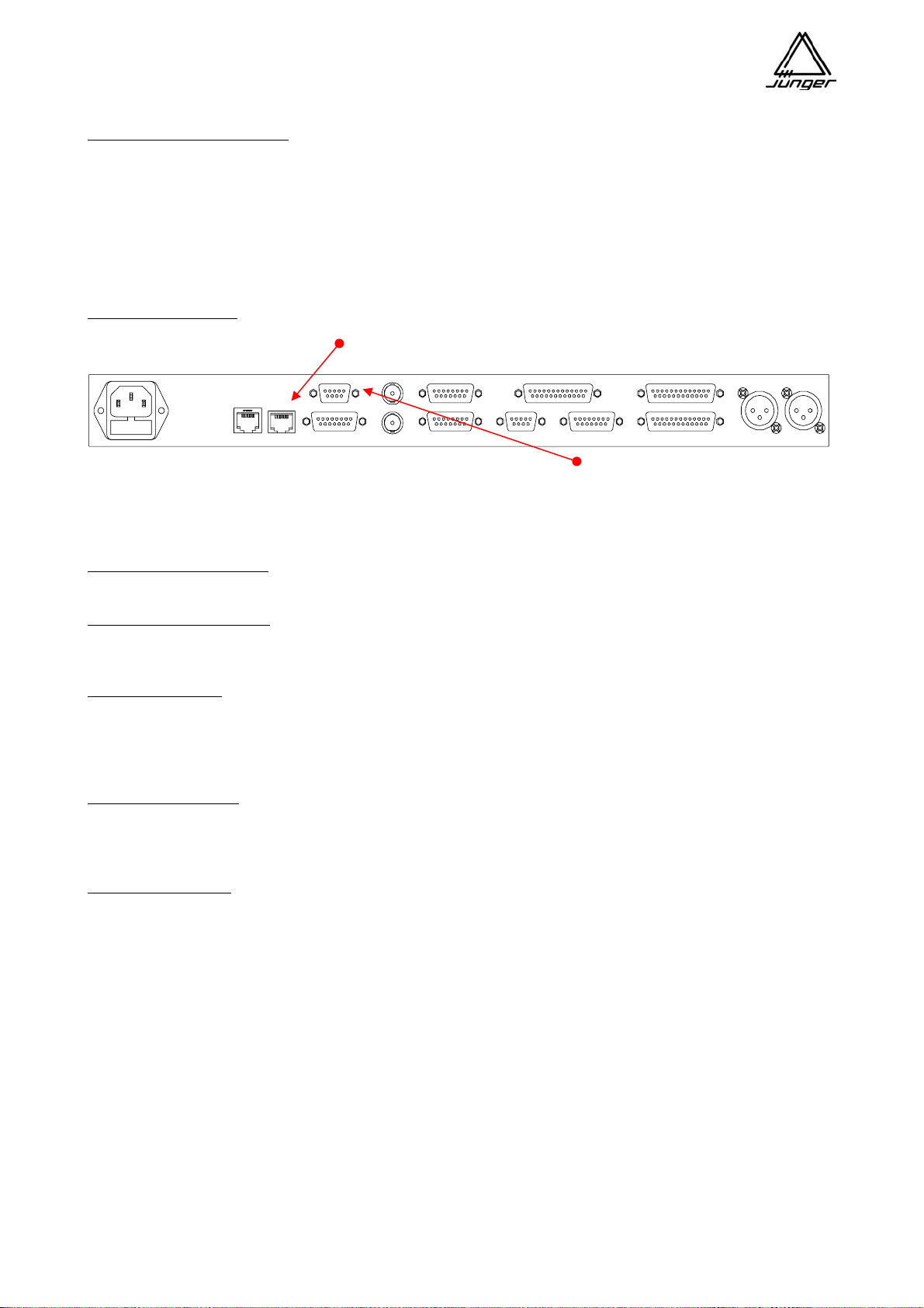
RS232
SYNC IN DIGITAL 1-4 IN MIC 2INTERFACE 1
INTERFACE 2
MIC 1
Ethernet
Remote
GPI / TALLY
DIGITAL BUS 1-4SYNC OUT
AUX OUT Phones / Speaker
ANALOG BUS 1-4
And into either jack on the back or bottom of the Console. connect the 9 pin cable between
If you need to extend this cable for more than 10m you a PC or from Laptop COM port or
will need an optional +5V power supply from Junger Audio. from a PC USB to serial converter
to RS232 connector
Microphone Connections :
Microphones can be connected directly to the XLR connectors.
Other Audio Connections :
For all other connections you need to make an adaptor cable to the multipin connectors. Please refer to the
Pin assignment at the end of this document.
Sync Connections :
Two BNC connectors are provided for Sync connection to and from the MIX4.
The MIX4 takes Word Clock, AES sync and video sync (if the optional sync board is installed) and
synchronizes all internal timing to one of these references if instructed by the system Setup software.
The sync output provides synchronous Word Clock.
GPI / O Connections :
A 15 pin Sub-D connector is provided for connecting external devices for parallel remote control.
Important note! Theses inputs are TTL type and should not exposed by external voltage in excess of +5V.
Ethernet Connector :
The Ethernet connector allows to hook up the MIX4 to a 10/100Mbit/s (auto negotiation) network. It complies
with CAT5. This interface is provided for external communication by TCP/IP protocol. It allows to set up the
MIX4 over the network. One other typical application is the remote control of a station router.
page 2
Page 6
Jünger Audio-Studiotechnik GmbH
MIX4 Principle Functions
The Junger MIX4 is a Digital Audio Mixer with 4 stereo full-featured Channel Strips.
The MX4 has 4 independent stereo mix busses, each of which can be independently configured :
Mix The Bus works as an ordinary stereo mix bus
Mix Minus Actually the same as a Mix config, but you don’t route one or more Strips to it.
PreMix The bus is used as a prefade Aux send.
PostMix The bus is used as a postfade Aux send.
Direct Out A prefade send from one and only one strip is routed to the bus.
Prefade Aux
Send Level
Level Controls marked
are controlled wit h the
Strip's Rotary Knob
Channel Strip I nput
Offset
Gain
*
*
Postfade Aux
Send Level
Strip
Fader
*
Channel
Gain
Level Control Simple Diagram
*
Prefade Aux Out
Postfade Aux O ut
Mix and Mix Minus Out
Direct Out
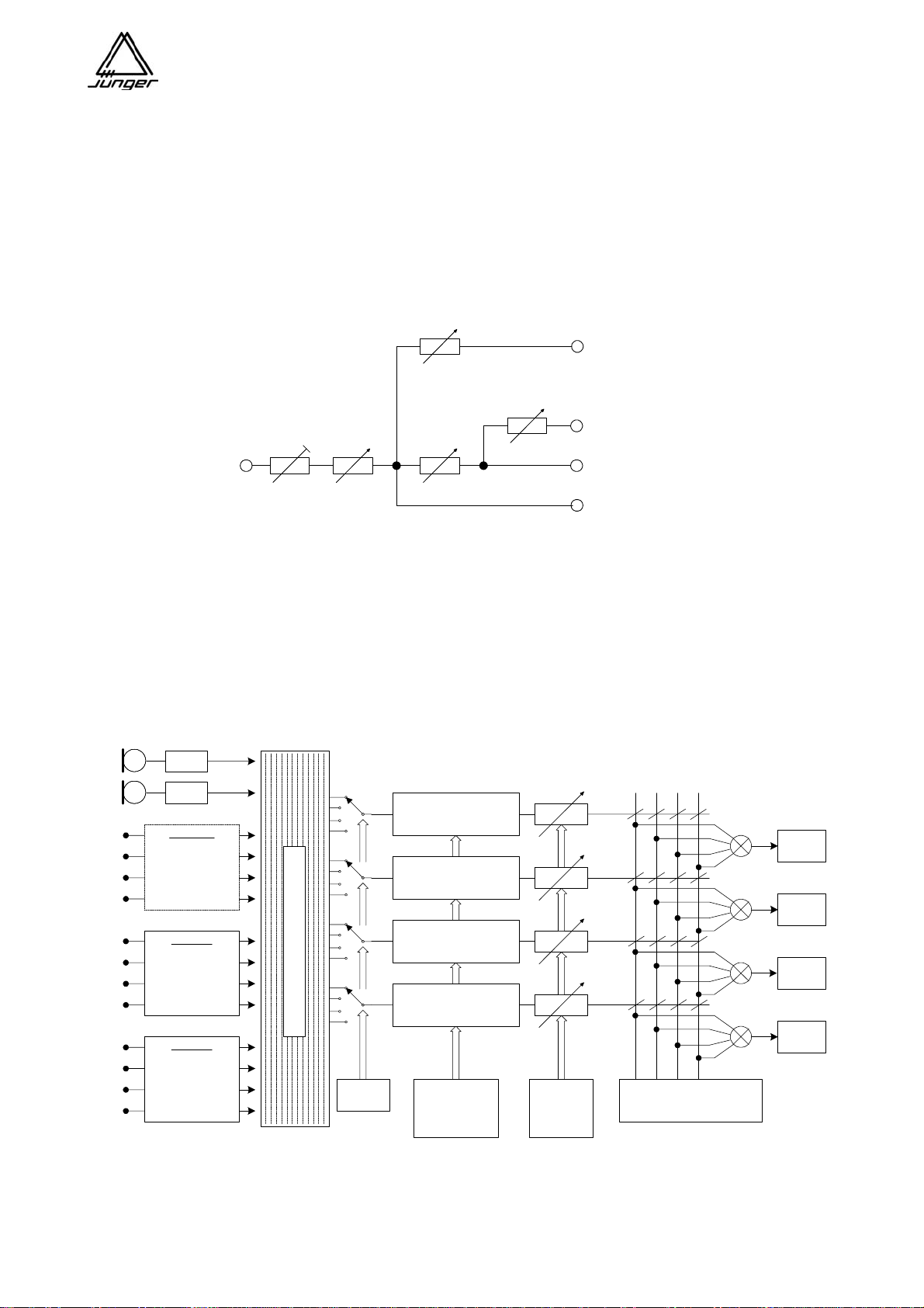
Each of the 4 Channel Strips of the MIX4 can be connected to one of the 14 inputs (sources).
Sources 1 and 2 are normally used for microphones but can be used for analog line level signals.
All other inputs are two channel sources and therefore they can carry two channel and stereo signals as well.
The settings of each Channel Strip are controlled and stored to the relating source it is conn ected to.
The bus outputs are available in both analog and AES digital.
Please see the block diagram below :
A / D
A / D
on board
4 AES / EBU
inputs with
sample rate
converters
IF slot 1
2 MIC
4 AES/EBU I/O
8 analog in
8 MADI Ch. I/O
8 SDI Ch. I/O
IF slot 2
2 MIC
4 AES/EBU I/O
8 analog in
8 MADI Ch. I/O
8 SDI Ch. I/O
s o u r c e m a t r i x
source
selection
Ch A
gain / phase / filter / EQ
dynamic processing
Ch B
gain / phase / filter / EQ
dynamic processing
Ch C
gain / phase / filter / EQ
dynamic processing
Ch D
gain / phase / filter / EQ
dynamic processing
parameter for
filter and
dynamic
processing
mix matrix
multiplier
coefficients
mix matrix including
channel selection and
multiplier
Each bus has a distortion free “brick wall limiter“ with Look Ahead feature to catch all peaks.
Bus
Limiter 1
Bus
Limiter 2
Bus
Limiter 3
Bus
Limiter 4
page 3
Page 7
Jünger Audio-Studiotechnik GmbH
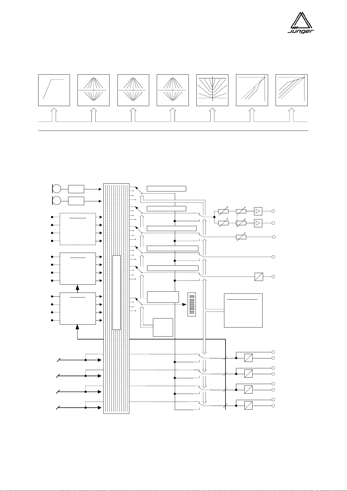
Each Channel Strip has a high pass filter, 3 band parametric EQ, and a dynamics section with expander,
compressor and de-esser. These processors use the same algorithms as the Junger Voice Proce s sor
modules.
g
low cut
parametric EQ compressorexpanderde-esserparametric EQ parametric EQ
p r o c e s s i n g p a r a m e t e r
The MIX4 has a sophisticated monitoring circuit. In addition to analog line level monitor output for monitor
amps and speakers, two headphone level outputs with offset level control are provided. Both outputs have
manual level setting by a turn pot at the desktop remote.
A / D
A / D
on board
4 AES / EBU
inputs with
sample rate
converters
IF slot 1
2 MIC
4 AES/EBU I/O
8 analog in
8 MADI ch I/O
8 SDI ch I/O
taklback source
headphone source
monitor (line out) source
AUX1 (digital) out source
AUX2 (analog) out source
headphone 1
headphone 2
monitor
line out
AUX 1 out
(digital)
D
A
AUX 2 out
(analog)
IF slot 2
2 MIC
4 AES/EBU I/O
8 analog in
8 MADI ch I/O
8 SDI ch I/O
DSP bus 1
DSP bus 2
DSP bus 3
DSP bus 4
Monitor and talkback matrix
internal meter
source
monitor
source
selction
talkback control :
local source
external source
destination
split mode
on / off
D
A
D
A
D
A
D
A
BUS 1 out
BUS 2 out
BUS 3 out
BUS 4 out
Also a sophisticated talkback system is provided by the MIX4 that can operate local talkback and remote
talkback. It also allows talking to the busses. Besides the 4 bus line outputs (analog and digital) there are two
auxiliary outputs AUX1 (digital) and AUX2 (analog), which can be used for external metering, talkback, extra
PFL output or other purposes as you require.
page 4
Page 8
Jünger Audio-Studiotechnik GmbH
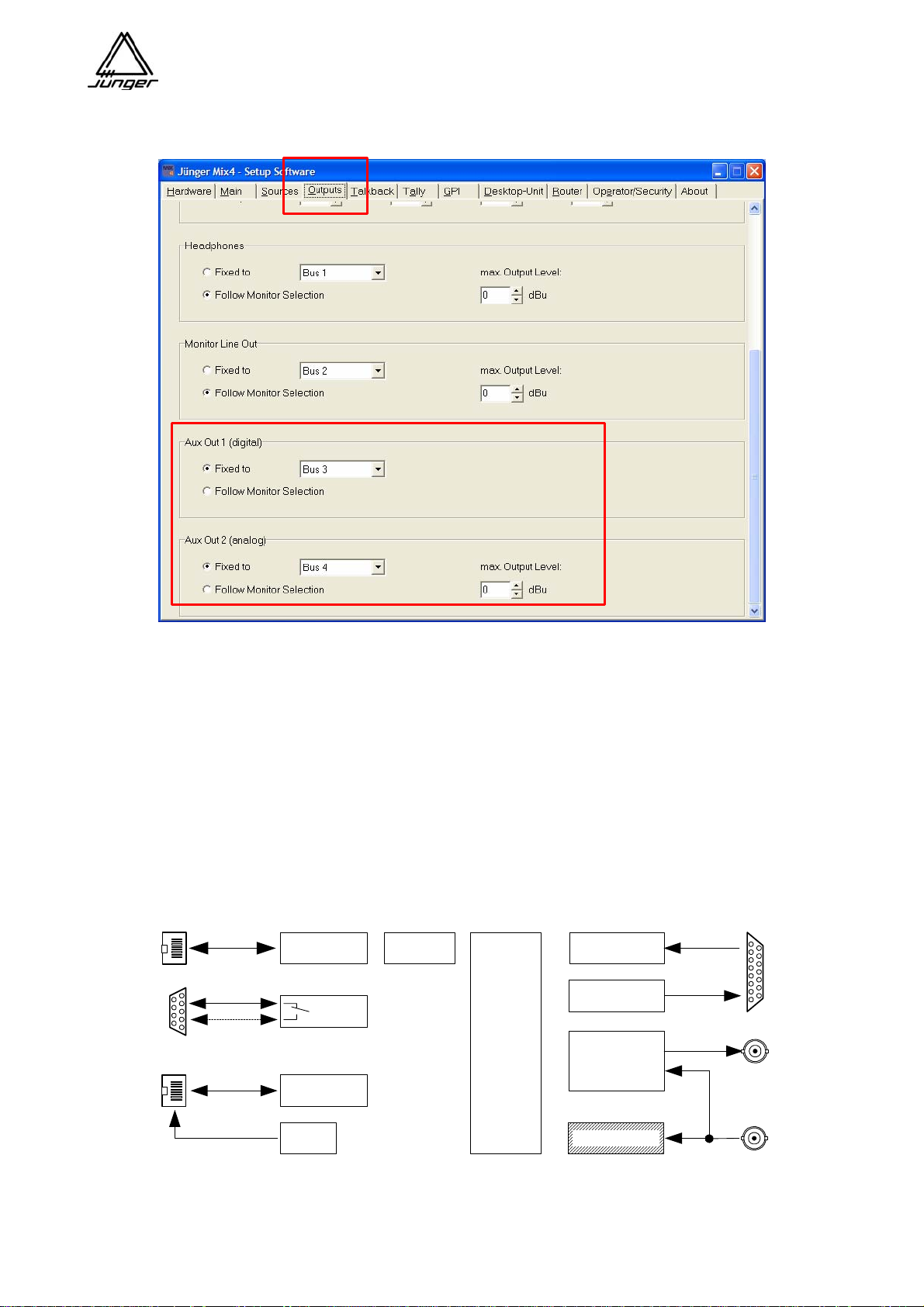
The signal available at these outputs is determined by the set up software :
The Setup software is an important part of the system because it allows for offline configuration of the MIX4
to fit it in almost every production environment from Edit Workstation to On Air. It serves for general
settings a user is not allowed to change from the desktop remote.
For remote control purposes the MIX4 is equipped with 8 tally outputs and 6 GPI inputs with TTL levels.
Their functions will be set by Setup software as well.
In addition, a TCP/IP over Ethernet interface allows the remote control of external routers via TCP/IP as well
as the centralized use of the setup software and the operator/preset/backup/restore tool over the
network.
There is also a serial interface for connection to a PC via RS 232 that serves for configuration of the MIX4.
This interface may also be used in RS 422 mode.
Ethernet
232
TCP/ IP 6 x GPI
8 x Tally
serial
422
remote connector
audio sync
WC out
CAN bus
optional
power
Firmware updates and the initial IP configuration are only possible via RS232 interface.
s y s t e m c o n t r o l l e r
video sync
sync in
page 5
Page 9

Jünger Audio-Studiotechnik GmbH
Management of MIX4 settings
The initial settings such as GAIN, PAN and bus assignment of a source are done within a channel strip.
Those parameters are always stored in relation to the source, i.e. if you select a specific source again on for
a channel strip, the parameters stored will automatically be activated.
The filter and dynamic settings are also set up by a channel strip. These settings are called
DSP parameters. You can save the DSP parameters (Phase, HP, 3xEQ, De-Esser, Expander, Compressor)
to presets. Later on you can load the data of such presets into any channel strip. When loading a preset, the
parameters will be applied to the source that is selected for that channel strip and will stay with that source.
As mentioned above, the MIX4 manages all parameters relating to a source. Therefore each source keeps
its DSP parameters even if you do not use it momentarily for a channel strip.
Important note : The data of presets will be applied in the same way as one would input it manually
step by step. It means that changing preset data later on will have NO effect for a source where that
preset has previously been used!
You can edit preset parameters off line by a PC based operator/preset/backup/restore tool. There you can
also give it a name. You can store sets of presets into files and/or send parts or all of it to devices of your
choice. Finally you can load a preset remote controlled into one or many channel strips.
The MIX4 has 11 areas for user data, called operators.
For each of the 11 operators there are 8 Snap-Shots. They contain the actual source assignment with all
parameters as well as the settings done in the <MON> menu from the desk top remote. Each operator can
have one set of monitor sources applied to the user buttons 1-4. By using the setup software you can name
the operators and apply individual security settings including a 4 digit PIN. This allows you to deny
operators access to several functions of the desktop remote and thereby prevent inexperienced personal
making operational mistakes. If you do not assign a PIN for an operator (0-0-0-0) the login happens without
interrogation. On logout all current settings of an operator are stored automatically.
An exception is the 1
st
operator named „Guest“. He will always be activated when you turn the MIX4 on.
This ensures that everybody can work with the MIX4 without being a registered operato r. Therefore no lo gin
is necessary. That is why you must store the settings which are to be loaded when you switch the unit on by
a special routine. You must press the buttons <USER> first and <no label> afterwards. The message
“Operator save“ will be displayed.
The data of the operators (content of their snap shots and last active conditions) can be managed with the
operator/preset/backup/restore tool. With this you can create sets of 10 operators ea ch and store these in
files at any place in the network and/or send them to devices. This tool allows you to create a backup for a
set of operators and load it later on into a similar device. You can also login individual operators over the
network.
Finally you can manage a set of all the data of a device. You can back it up and restore it later on. This
function may ease the exchange of units in the field without restoring setups, operator profiles and presets
but back up the unit at once.
page 6
Page 10
Jünger Audio-Studiotechnik GmbH
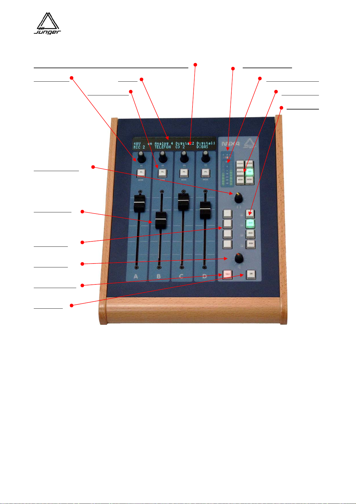
MIX4 Desktop Remote
The MIX4 is controlled by its remote control unit :
Channel Rotary Knob (turn & push function) - Rotary Knob
Correlation display
Channel LED
Display 16 place LED meter
Channel Button
Setup Buttons
Bus Buttons
Headphone level
Channel fader
User buttons
Monitor level
Talkback button
Dim button
page 7
Page 11
Jünger Audio-Studiotechnik GmbH
MIX4 Display System
The Mix 4 is based on a configurable hardware architecture that allows for multiple settings and
configurations. This way the MIX4 can be setup for different working environments and be tailored to the
individual user via Mix 4 Setup software that runs on a PC.
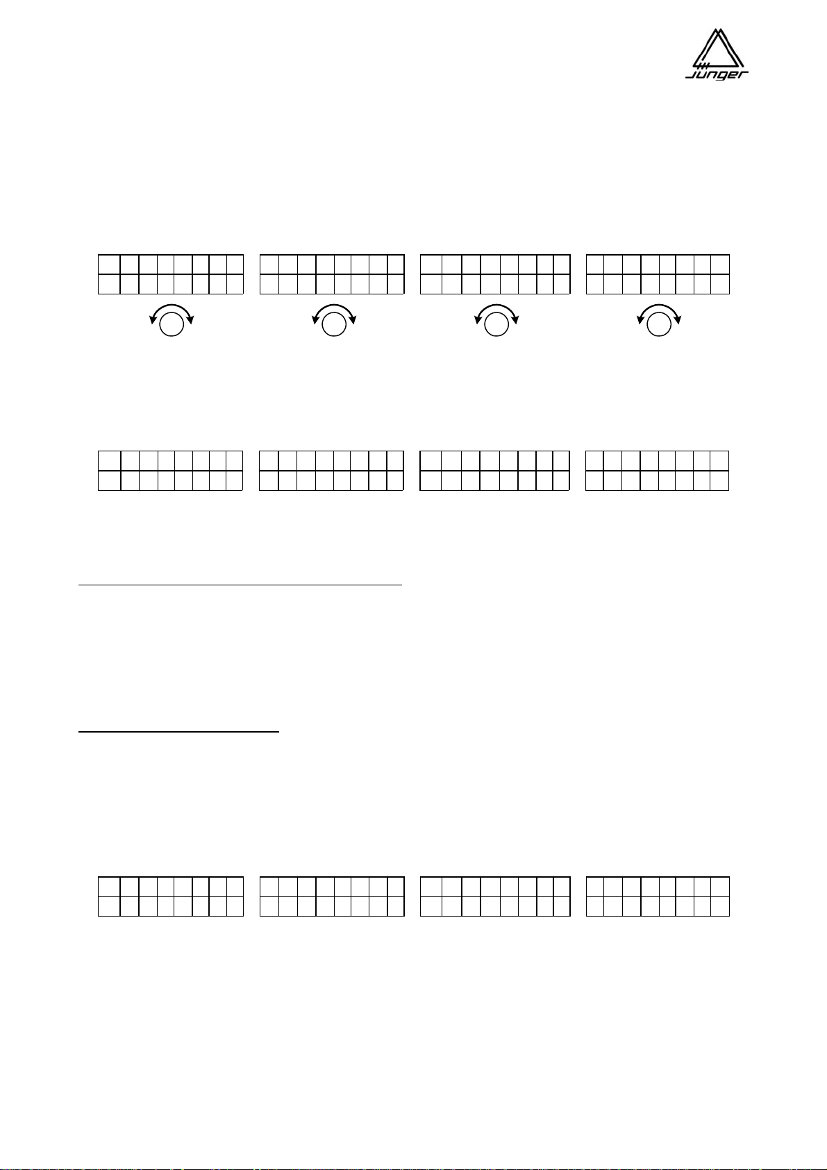
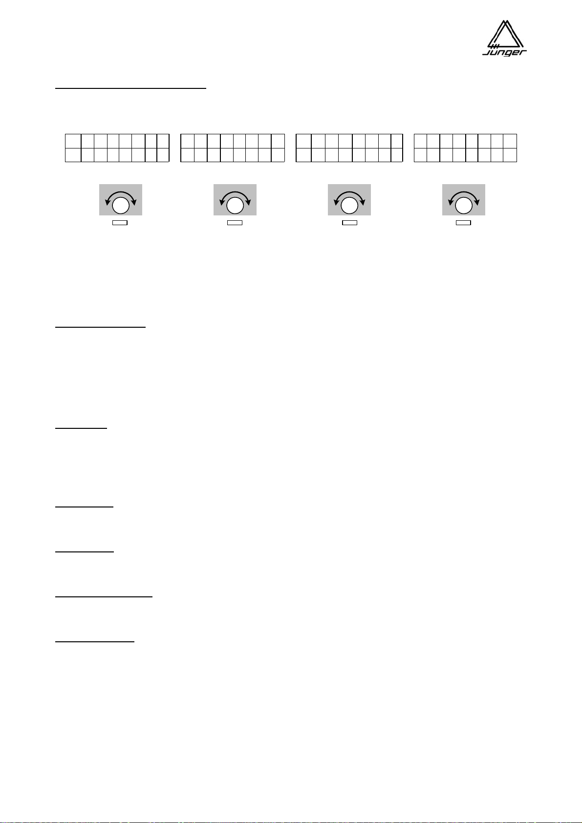
The configurable hardware centers around 4 Channel Strips labeled A, B, C, D, each with a fader,
Channel Button, Rotary Knob (a continuous turn encoder), and a two line 8 character display,
with characters screened on the front panel above the top line as shown here :
L C R 1 2 3 4 L C R 1 2 3 4 L C R 1 2 3 4 L C R 1 2 3 4
M i c 1 T e l e f o n C D 3 J i n g l e 1
The lower line displays the actual source name.
As needed, characters in the top line of these displays are turned on, to ‘point’ to the legends
(L, C, R, 1, 2, 3, 4) screened on the panel just above the top row of the display :
L C R 1 2 3 4 L C R 1 2 3 4 L C R 1 2 3 4 L C R 1 2 3 4
-
-
M i c 1 T e l e f o n C D 3 J i n g l e 1
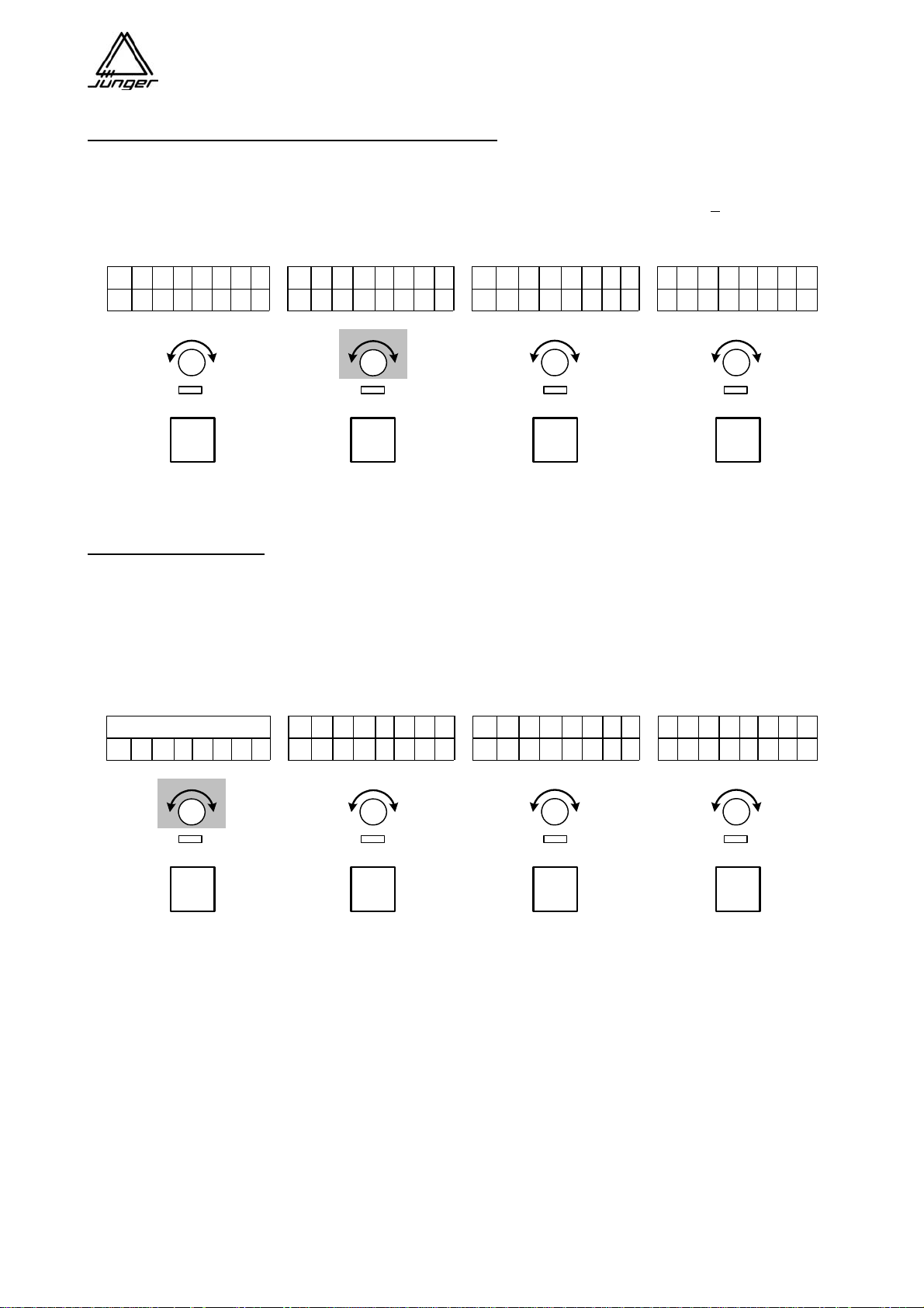
During normal operation, the Mix 4 is in the MIX mode – i.e. no SETUP Button, as shown above, on the
remote is activated. While in MIX mode, the Output bus routing for each Channel Strip is displayed by small
symbols in the upper line pointing at the legends on the panel.
Screened legend 1 - 4 (number of the MIX busses) :
-
- assignment to a Mix bus (respective source must not be assigned for a Mix Minus bus)
^ - assignment to a Direct Out bus (only one source per Direct Out)
x
- this bus is configured as Pre- or Postfade AUX Mix and therefore routing is via the
Aux Level control (Pre- or Postfade depending on the Bus Mode)
At the same time, on the left end of the top line of the display, the nature of the source for the Channel Strip
is shown :
Screened legend blank, L, C, R :
blank
L - the source of the MIX4 Channel Strip is two channel where the actual audio signal is derived
from the left channel
C - the source of the MIX4 Channel Strip is stereo but has been turned into mono (L + R - 3dB)
or a MIC signal is assigned that is a mono signal by definition
R - the source of the MIX4 Channel Strip is two channel where the actual audio signal is derived
from the right channel
L C R 1 2 3 4 L C R 1 2 3 4 L C R 1 2 3 4 L C R 1 2 3 4
-
M i c 1 T e l e f o n C D 3 J i n g l e 1
The bus assignment above shows a sample configuration of a Mix bus (BUS1), a Mix Minus bus (BUS2) as
well as a Direct Out bus (Mic1 on BUS3). BIUS4 can not be assigned for standard Mix mode because it is
set up for as a Prefade or Postfade AUX Mix.
- the source of the MIX4 Channel Strip is stereo
- -
^
x
-
- x
- -
x
- -
x
page 8
Page 12
Jünger Audio-Studiotechnik GmbH
Operation
When switched on, the MIX4 starts up in the Mix mode :
Depending on the Setup, the Channel Buttons are PFL / MUTE / START or HYBRID and the
Channel Rotary knob acquire a GAIN / PAN / BALANCE / Prefade or Postfade function.
Turning a Channel Rotary Knob changes the gain of the respective MIX4 Channel Strip by +
15dB, as shown
here for Channel Strip B (#2), with the GAIN set to +6 dB :
L C R 1 2 3 4 L C R 1 2 3 4 L C R 1 2 3 4 L C R 1 2 3 4
-
- -
x
G A I N + 6
^
- -
x
- -
x
M i c 1 T e l e f o n C D 3 J i n g l e 1
PFL
PFL
PFL
PFL
Important note! After two seconds of no turning of the knob, the display changes back to the Mix mode
display, like the other three Strips show in this example.
PAN / BALANCE mode :
A push on the Channel Rotary Knob switches it to the PAN / BALANCE mode.
When a mono source - underlined L or R or C - is assigned to the MIX4 Channel Strip it is a
PAN function (This might be used when you have say two microphones in an interview situation, with
one panned to the left, the other to the right).
When a stereo source - L or R or C not underlined - is assigned, a BALANCE control is performed.
L C R 1 2 3 4 L C R 1 2 3 4 L C R 1 2 3 4 L C R 1 2 3 4
_____|____________________
-
- x
- -
x
- -
M I C 1 T e l e f o n C D 3 J i n g l e 1
x
PFL
PFL
PFL
PFL
The vertical line marks :
the position of the (mono) source within the sound image.
or
the balance of the stereo signal.
Important note! After two seconds of no turning of the knob, the display changes back to the mix mode
display, like the other three Strips show in this example.
page 9
Page 13
Jünger Audio-Studiotechnik GmbH
Prefade / Postfade Send Levels :
When one bus or more buses are configured as Prefade mix or Postfade mix and the respective BusMonitor button is pressed then the top display line shows level of each channel to the mix, e. g. <Bus 3>
L C R 1 2 3 4 L C R 1 2 3 4 L C R 1 2 3 4 L C R 1 2 3 4
P r e F a d e r M i x B u s 3
o f f - 1 0 , 0 d B o f f + 3 , 0 d B
The Mic 1 is currently not yet assigned to Prefade bus3, and by turning the Channel Rotary Knob A it is
included in the mix with -83 dB and can be modified by further turning the Channel Rotary Knob by up to +10
dB.
Important note! This display is left by pushing another Bus Monitor button.
Button operations :
Buttons which control external devices or perform PFL or DIM can operate in two different modes:
Toggle switch operation
If one presses the button once briefly the function will be turned on
If one presses the button once briefly again the function will be turned off
Push button operation
If one presses and holds the button the function will be turned on
If one releases the button the function will be turned off
Shortcuts :
For quick access to the first eight Presets or one of the 8 Snap-Shots there is a shortcut function
implemented. Pressing the <DSP> button first and one of the <USERx> or <BUSx> buttons afterwards
loads the respective Preset into the Channel Strip which has been pre selected by the setup softwa re.
Pressing the <USER> button first and one of the <USERx> or <BUSx> buttons afterwards loads the
respective SnapShot.
N-1 busses :
The MIX4 knows one N-1 bus configuration to operate a telephone interface. This function is called HYBRID
(s. p. 57). All other N-1 configurations must be set manually.
PFL modes :
The MIX4 has exclusive and summing PFL functions that can be turned off and on automatically, depending
on the fader position (s. p. 20).
Test tone generator :
For testing purpose of outgoing lines you can route a 1kHz test tone to the busses of the MIX4 (s. p. 20). The
level of that signal can be set from the desktop remote.
Monitor section :
The 4 busses of the MIX4, sources (MIX4 inputs) assigned to Channel Strips and those not assigned to a
Channel Strip can be monitored via the monitor root (functions called: bus monitoring, PFL and source
monitoring). The monitor line output and two parallel headphone outputs are connected to that root. Both
headphone outputs together and the monitor line output have level controls to set the monitoring loudness.
Two auxiliary outputs (analog and digital both 2CH) may also be connected to the monitor root by use of the
setup software (e.g. to connect an external meter to the MIX4). The LED level and phase display has only
effect for bus monitoring and for PFL. It is not active for source monitoring.
page 10
Page 14

Jünger Audio-Studiotechnik GmbH
Buttons of the MIX4
Channel Buttons show :
Mute info
* off (light out) to indicate their MUTE function
* bright red as long as MUTE is performed
Phone Hybrid info
* dark yellow to indicate their PFL or HYBRID function
* blinking dark yellow if there is an incoming call from a telephone hybrid
* bright yellow when PFL / HYBRID is on in the channel strip
* blinking bright yellow to indicate that there is still an active call
Remote START info
* bright green when START was engaged (pushing it again triggers STOP)
Channel-Select info
* blinking green when the CHANNEL-SELECT function is engaged in the Setup mode
External Router info
* blinking green/yellow if you select an input to which a router trunk line is assigned
* blinking red / yellow when external router control is engaged – group selectio n mode
* blinking yellow when external router control is engaged in – source selection mode
User Buttons show :
Setup info
* blinking yellow as long as they are being programmed
Monitor function info
* off (light out) to indicate their monitor function
* bright green when monitor function is engaged
* bright yellow to indicate their LL or RR monitor function
Phone Hybrid info
* blinking bright green to indicate that talk to hybrid is possible
Event info
* bright green, red or yellow depending on the setup of such button
Bus Buttons show :
Setup info
* blinking yellow as long as they are being programmed (when function available)
Monitor function info
* off (light out) to indicate their MONITOR function
* bright green when the MONITOR function is performed
* dark yellow to indicate that they are assigned to another function than monitor
Setup Buttons show :
* off (light out)
* light green when the dedicated function is performed
The functions of the MIX4 are reached via Setup Buttons listed here. Details for each are further on.
<no label>
Displays software releases / operator init by pressing <USER> simultaneously
<SOURCE> selection
Source selection for the Channel Strips of the MIX4
<BUS> assignment
Assignment of the Channel Strips to the buses
<DSP> parameter
Control of the DSP functions (Phase/Filter/EQ/Dynamics)
<USER> operator management
Operator log in / out, snap shot load and store, Preset load and store
<MONITOR> assignment
Assignment of monitor sources, gain setting for headphones and Talkback, PFL options,
set up of the 1kHz test tone generator
With examples of source names and bus assignments we will now explain the possibilities of the MIX4.
The explanations are structured according to the functions of the Setup buttons.
page 11
Page 15
Jünger Audio-Studiotechnik GmbH
<SRCE> Source Selection
Here you define the source for the respective Channel Strip of the MIX4.
The MIX4 differentiates between :
2-channel sources (L
or R underlined in the display at the top of the Strip)
stereo sources (without labeling).
mono sources (C
underlined)
When a Channel Strip’s input is setup for a 2-channel source (i.e. the 2 channels are independent, not an LR
pair), then either of the 2 inputs can be selected as a source for a Strip, sending the same signal out of the
Strip to the L and R sides of the stereo busses. This function can be assigned permanently by Setup
software to every input. The Setup option is called “force 2Ch”.
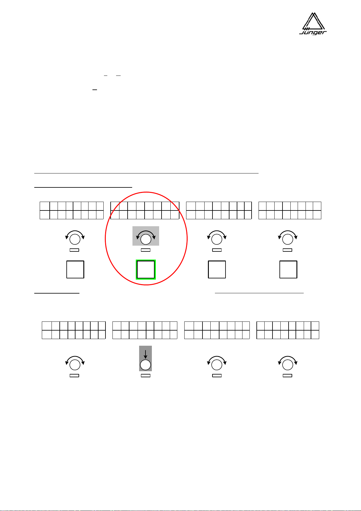
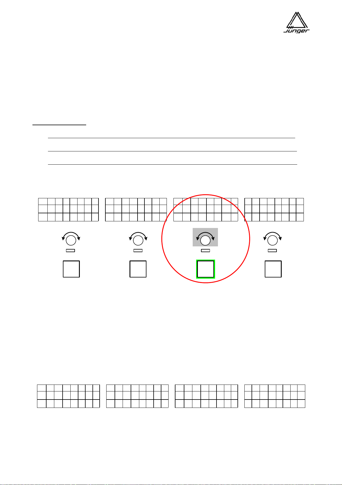
After pressing <SRCE>, you then push the channel button of the Strip where you want to change the input
source. In the example below, we are changing the input source for Strip B (#2). After pushing the Channel
Button on Strip B, the Strip’s display will show the status of that source in the top line and, the source name
(assigned using the Setup software on the PC) on the bottom line.
Pushing the Channel Rotary Knob switches the source selection to 2-channel mode
and will select the LEFT
channel.
Repeated pushing - called “3 push”
leads to RIGHT channel and back to STEREO mode and so forth.
L C R 1 2 3 4 L C R 1 2 3 4 L C R 1 2 3 4 L C R 1 2 3 4
-
- -
^
x
M i c 1
S T E R E O
V T R _ 3
- -
C D 3 J i n g l e 1
x
- -
x
PFL
PFL
PFL
PFL
Important Note!
If this input is selected on another Channel Strip, it will be switched over there also. When
selecting 2-channel mode in this case for both Channel Strips the left channel will be selected in the first, as
shown below for channel B :
L C R 1 2 3 4 L C R 1 2 3 4 L C R 1 2 3 4 L C R 1 2 3 4
-
- -
^
x
M i c 1
L E F T
V T R _ 3
- -
C D 3 J i n g l e 1
x
- -
x
page 12
Page 16
Jünger Audio-Studiotechnik GmbH
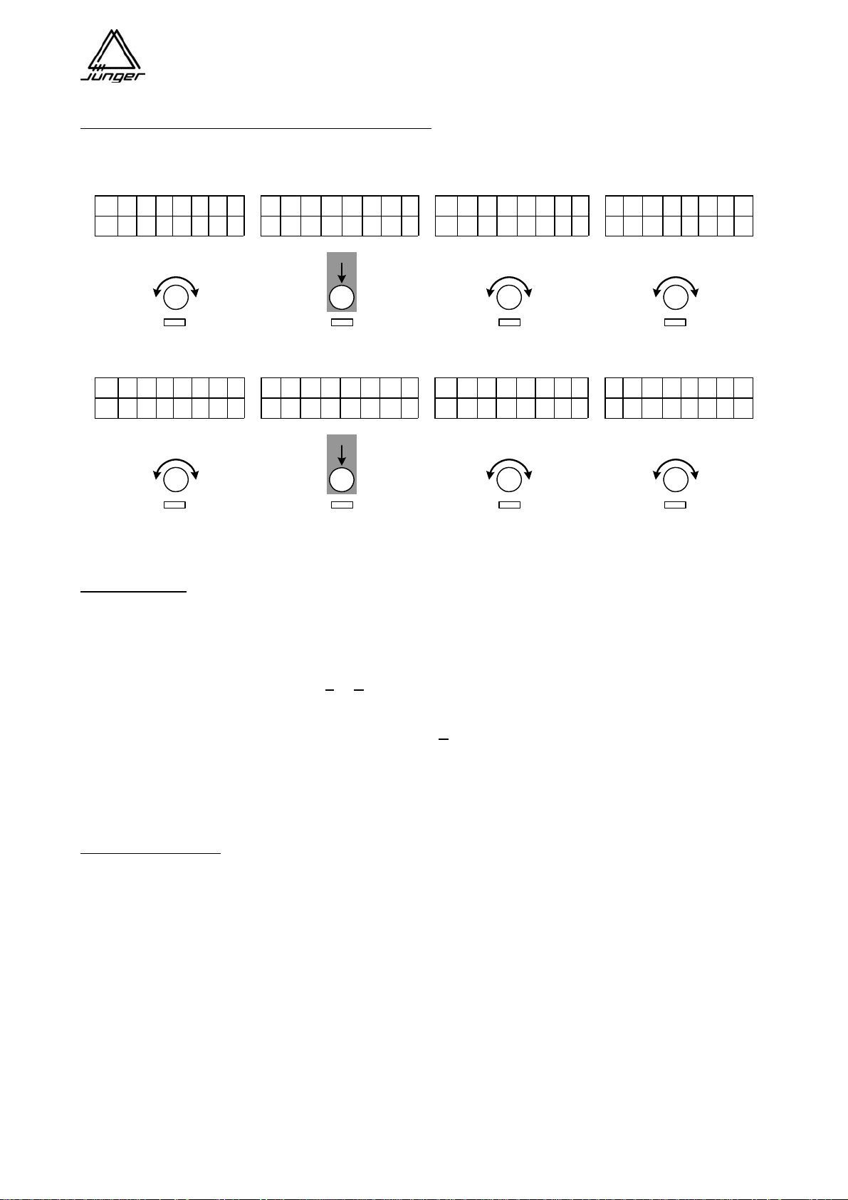
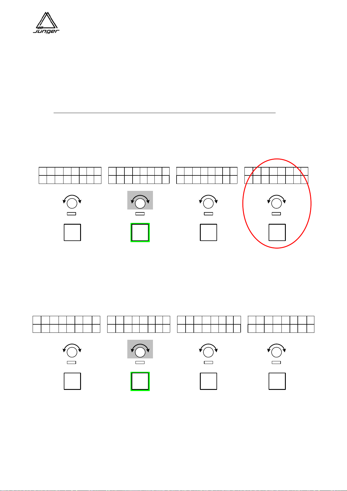
Continuing to turn the Channel Rotary Knob to the right
will select the next possible source, which would
be the right channel of the 2-channel source “VTR_3 R” in this example :
L C R 1 2 3 4 L C R 1 2 3 4 L C R 1 2 3 4 L C R 1 2 3 4
-
- -
^
x
M i c 1
R I G H T
V T R _ 3 R
- -
C D 3 J i N g l e 1
x
- -
x
L C R 1 2 3 4 L C R 1 2 3 4 L C R 1 2 3 4 L C R 1 2 3 4
-
- -
^
x
M i c 1
S T E R E O
V T R _ 3
- -
C D 3 J i N g l e 1
x
- -
x
You may also select the opposite channel via “3 push” by pressing the Channel Rotary Knob several times
or by the standard turning function of that knob.
Important Note!
Stereo / 2-channel switch over is only possible via pressing of the Channel Rotary Knob.
While source selection is possible by either turning or pushing the Rotary Knob.
If in continuous operation for 2-channel mode the content of the channels has changed (u sually happens
with VTRs when voice on track one and clean feed on track two or vice versa) you can quickl y switch to the
other channel by pressing <SRCE> and then the respective channel rotary knob. The underscore in the
upper line of the display changes from L
to R respectively (or vice versa).
If a stereo source is selected for that Channel Strip, pushing the Channel Rotary Knob alternates between :
mono (L+R -3dB) marked by an underscore under C
and
stereo (without underscore).
Pushing <SRCE> again terminates the source selection.
Router Tie Line Inputs
It is possible to configure Mix 4 line inputs to be connected to Tie Lines, which in turn are connected to an
external router. This router can then be controlled by the Mix4 to allow selections of its inputs to be routed to
the Mix 4 Inputs.
If the MIX4 is connected with an external router, special MIX4 firmware to interface to the control
system of that router must be installed and activated in the MIX4.
The first time you dial up one of these tie line inputs on the Mix4, the display will show both names preset in
Setup software and the Channel Button will start blinking green/yellow to show this special situation :
page 13
Page 17
Jünger Audio-Studiotechnik GmbH
L C R 1 2 3 4 L C R 1 2 3 4 L C R 1 2 3 4 L C R 1 2 3 4
-
- -
^
x
M i c 1
S T E R E O
T i e L i n E 1
- -
C D 3 J i n g l e 1
x
- -
x
PFL
PFL
PFL
PFL
Pressing that Channel Button will give you control of the external router so you can select the desired input
for the MIX4. The channel button will blink yellow or yellow/red to indicated that you are controlling
the external router. By turning the Rotary Knob one will select router sources (blinking yellow) or groups of
sources (blinking yellow/red) first, depending on the external router brand / type :
L C R 1 2 3 4 L C R 1 2 3 4 L C R 1 2 3 4 L C R 1 2 3 4
-
- -
^
x
M i c 1
G R P D A T
D A T P L 4
- -
C D 3 J i n g l e 1
x
- -
x
PFL
PFL
PFL
PFL
The top line now shows the group name and the bottom line now shows the source name of the selected
source of the external router. The selected source will be available for that input (and therefore for the
Channel Strip of the MIX4) immediately.
Pushing the Channel Button again will switch back to initial source selection mode and the LED of the
Channel Button will turn off. In this case the display will show the name of the tie-line again not the name of
the router source! But if you push <SRCE> instead of the channel button at this time the display will show
the router source name.
If router sources are organized in groups that second push will lead one level down to sele ct a source within
a pre-selected group (see above). In this case the channel button will blink yellow now to indicate that
turning the Rotary Knob will now select a source from that group.
Pushing <SOURCE> will terminate the function.
Notes about different control concepts for router from different manufactures :
Klotz VADIS II
In this case, 16 sources for each MIX4, connected to a VADIS system, must be pre-selected in within the “Junger Audio DDE client”
(see extra description for VADIS operation). Thus you will get 16 more (external) sources for the MIX4.
LAWO / Mandozzi / DHD
By use of Setup software, 16 groups by 8 sources can be pre-selected for the respective system which the particular MIX4 can
select afterwards. There are two levels of controlling such a router. One needs to select one of the groups first and afterwards one
of the sources from that group.
page 14
Page 18

Jünger Audio-Studiotechnik GmbH
Important note! When you are selecting an external source for the MIX4
(see above) there are two ways to leave this mode (see 4.1 or 4.2 below) :
0. Turn source selection mode on by pressing the <SRCE> button.
1. Select a Channel Strip where you want to assign an external source to.
Press a Channel Button - Channel Button is blinking green.
2. Search for an input (tie line) that is connected to an external router destination port.
Turn the Channel Rotary Knob until - Channel Button is blinking green / yellow.
3. Turn external control on.
Press that Channel Button - Channel Button is blinking red/yellow or yellow
3.1 Select a source if blinking yellow (Klotz Digital VADISII)
Turn the Channel Rotary Knob to select a source
3.2.1 Select a Group if blinking red/yellow (LAWO / Mandozzi / DHD)
Turn the Channel Rotary Knob to select a group
3.2.2 Select a source from a (pre selected) group.
Press that Channel Button again - Channel Button is blinking yellow
Turn the Channel Rotary Knob until the router source name appears in the Channel
4. Turn source selection mode off.
4.1 Press <SRCE> button - Channel Button turns off
The name of the external source will stay in the Channel Display.
4.2 Press that Channel Button - Channel Button turns off
The name
of the local input (i.e. the name of the tie line) will appear in the Channel Display
You must press <SRCE> afterwards to leave source selection mode!
page 15
Page 19
Jünger Audio-Studiotechnik GmbH
<BUS> Assignment and Bit Transparent Mode
This is where you route the output of a MIX4 Channel Strip to one or more of the possible buses.
Possible buses here are the Mix bus, the Hybrid bus (a function to operate a telephone hybrid that also
means a Mix Minus or clean feed to that bus) and the Direct Out bus.
You do not need to define Mix Minus busses – just don’t assign one or more sources to bus and voila
– you have a mix minus!
Why make a Mix Minus? Perhaps to prevent feedback or to keep a source out of
headphones.
If you later call such source again the bus assignment will be preserved because the MIX4
“remembers” all source related settings.
Special Bus Notes :
In general for the same stereo source the bus assignment is the same in different Channel Strips.
If one source is set for 2-channel mode it can have different bus assignments in different channels
.
The initial bus assignment is taken from the previous stereo setting
When changing that source back to stereo, the bus assignment will be taken from the left channel.
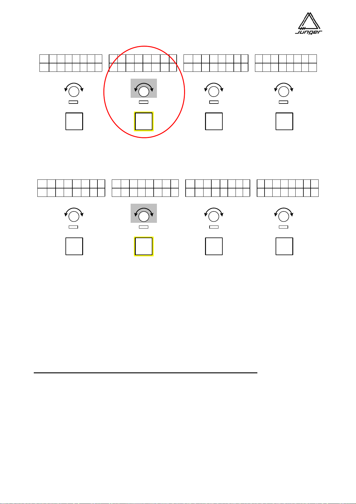
Generally, after pushing <BUS> you press the Channel Button in which the bus assignment is to be
changed – channel C for this example. After pressing the Channel Button on C, the display in this Channel
Strip will show a small triangle which can be moved below the numbers 1 - 4 by the Channel Rotary Knob :
L C R 1 2 3 4 L C R 1 2 3 4 L C R 1 2 3 4 L C R 1 2 3 4
-
- -
^
x
-
- x
M i c 1 T e l e f o n
CD 3
- -
J i n g l e 1
x
- -
x
PFL
PFL
PFL
PFL
To select a bus to route to from C, point at it with the arrow and then push the Channel Rotary Knob.
Buses that are configured as Prefade / Postfade are marked in the display by a small ’x’ and cannot
be selected by the ‘arrow’. Channels are always assigned to these busses. The Cha nnel Rotary
Knob (Aux Send) on each channel adjusts the send level to the busses anywhere from
‘Off’ (AKA ‘not routed’) to +10 dB.
Buses that were configured for Direct Out can “route out“ only one source. Such a bus is marked by a tip to
the top. There always the last selected MIX4 Channel Strip (and thus the assigned source) is “routed out”.
The <BUS> button also allows for set up of the Bit Transparent Mode, i.e. data put through from a source
to a bus output. In this case the bus can not be monitored to avoid unexpected high levels from data signals.
The respective analog output will be muted while the source label changes to DATA and PFL function is
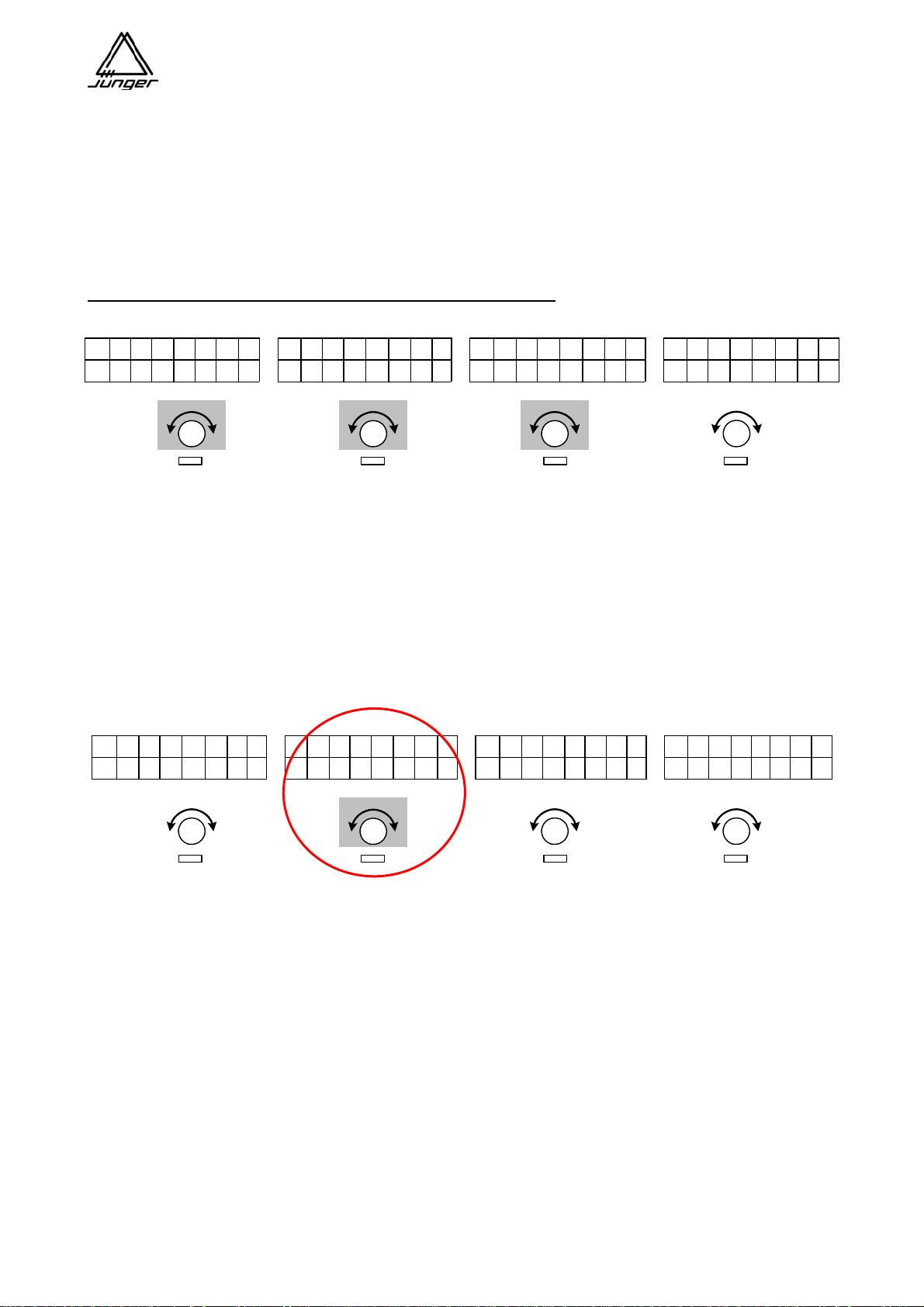
turned off for such a source. After pressing <BUS> you must press the <no label> button :
L C R 1 2 3 4 L C R 1 2 3 4 L C R 1 2 3 4 L C R 1 2 3 4
B U S 1 B U S 2 B U S 3 B U S 4
O f f D i g i t l 1 O f f O f f
With the respective Channel Rotary Knob you can select one of the available digital sources as data input for
that bus output. In the above example the input DIGITAL1 is connected with the digital outputs of bus 2.
page 16
Page 20
Jünger Audio-Studiotechnik GmbH
<DSP> Parameter
Here you control the filters, Eqs, and the dynamics section of each Channel Strip.
Generally, after a push on <DSP> you then press the Channel Button of that Channel Strip for which you
want to change settings.
Important note! If PFL is already activated before pressing <DSP>, you be adjusting the DSP settings while
in PFL mode, rather that while listening to the BUS monitor.
For this example channel button B is pressed.
The knobs and displays on all the Strips will now be used to adjust DSP settings on B.
The display shows the selected parameter for DSP processing section in the bottom line of Channel Strip A
(PHASE is first parameter offered for adjustment).
In channel D one can turn the whole DSP function on and off ’BYPASS’ by pressing
Channel Rotary Knob D :
L C R 1 2 3 4 L C R 1 2 3 4 L C R 1 2 3 4 L C R 1 2 3 4
P H A S E
p l u s
C h D S P
o f f
PFL
PFL
PFL
PFL
Turning the channel rotary knob B changes the parameter value between plus and minus. Turning the
channel rotary knob A selects the processing sections :
PHASE / LOW CUT / EQ 1 to 3 / DE-ESSER / EXPANDER / COMPRESSOR
In the Channel Strip displays appear then the parameters of the respective DSP section and their respective
values. The Channel Rotary Controls of the other MIX4 Channel Strips change their parameter values
accordingly :
L C R 1 2 3 4 L C R 1 2 3 4 L C R 1 2 3 4 L C R 1 2 3 4
o n
R A T I O RANGE P R O G RAM
C O M P R E S S 1 . 5 / 1 + 1 0 d B 3
PFL
PFL
PFL
PFL
Pushing the Channel Rotary Knob in channel A will disable the processing section displayed i n Channel
Strip A
Pressing another Channel Button changes to that Channel Strip.
Pushing <DSP> again terminates the function and MIX4 returns to the mix mode.
page 17
Page 21

Jünger Audio-Studiotechnik GmbH
Compilation of the DSP processing sections and their parameters as well as their displays:
Channel-strip
Display 1st line Display 2nd line
A Selection of the DSP section :
N (0 to 7) Gain reduction DSP section
0= PHASE, 1=LOWCUT
2=EQ1, 3=EQ2, 4=EQ3 (see display)
5=DE-ESSER, 6=EXPANDER
7=COMPRESS
B First parameter of the section N.1 parameter name parameter value
C Second parameter of the section N.2 parameter name parameter value
D Third parameter of the section N.3 parameter name parameter value
The table compiles the parameters and their setting range of the individual sections:
# Name
0 LEFT plus / minus
1 FREQ OFF, 40, 60, 80, 100, 120 Hz
2.1 FREQ 50 ... 500 Hz
500 Hz ... 5 kHz
5 kHz ... 15 kHz
2.2 Q LS, HS, 0.5 ... 8
2.3 RANGE -15 ... 0 ... 15
3.1 FREQ 50 Hz ... 500 Hz
500 Hz ... 5 kHz
5 kHz ... 15 kHz
3.2 Q LS, HS, 0.5 ... 8
3.3 RANGE -15 ... 0 ... 15
4.1 FREQ 50 Hz ... 500 Hz
500 Hz ... 5 kHz
5 kHz ... 15 kHz
4.2 Q LS, HS, 0.5 ... 8
4.3 RANGE -15 ... 0 ... 15
5.1 TYPE FEM, MAL, 1 ... 14
5.2 RANGE 0 ... –20
6.1 THRESH OFF, -60 ... –20 dB
6.2 RANGE -40 .... 0 dB
6.3 ATTACK 0.2, 0.3, 0.4, 0.5, 0.7, 1.0, 1.5, 2.0, 3.0, 4.0
7.1 COMP RAT OFF/ 1: 1.3, 1.6, 2.0, 3.0, 4.0
7.2 COMP RNG 0 ... 15
7.3 COMP PRO 1 .... 9
Value Range
in 5 Hz steps
in 50 Hz steps
in 500 Hz steps
in 0.5 unit steps
In 1 dB steps
in 5 Hz steps
in 50 Hz steps
in 500 Hz steps
in 0.5 unit steps
In 1 dB steps
in 5 Hz steps
in 50 Hz steps
in 500 Hz steps
in 0.5 unit steps
In 1 dB steps
In 1 unit steps
In 1 dB steps
in 2 dB steps
In 1 dB steps
In 1 dB steps
in 1 unit steps
Description
For stereo sources only L (plus/minus)
High pass filter
EQ1 mid frequencies
EQ1 mid frequencies
EQ1 mid frequencies
EQ1 type: LS=Low Shelf, HS=High Shelf, Q
EQ1 attenuation / amplification
EQ2 mid frequencies
EQ2 mid frequencies
EQ2 mid frequencies
EQ2 type: LS=Low Shelf, HS=High Shelf, Q
EQ2 attenuation / amplification
EQ3 mid frequencies
EQ3 mid frequencies
EQ3 mid frequencies
EQ3 type: LS=Low Shelf, HS=High Shelf, Q
EQ3 attenuation / amplification
e-esser frequency
Working depth of the de-esser
Expander threshold value
Expander range
Expander response time
Compressor ratio
Compressor amplification
Processing parameters of the compressors
page 18
Page 22
Jünger Audio-Studiotechnik GmbH
<MON> Monitoring Feature
This function allows the assignment of sources to the individual buttons of the MIX4 for monitoring purposes.
Sources that are not in use on MIX4 Channel Strips can be monitored in this way.
Important note! Because this monitor signal is not processed by the DSP, no GAIN / PAN / BALANCE or
DSP is possible. You will be listening to the ‘raw’ input signal.
Furthermore, here one can set both the offset gains of the two headphone outputs and the gai n of the
talkback source and the PFL modes as well as the 1kHz test tone generator.
Pushing the <MONITOR> button leads to the following display :
L C R 1 2 3 4 L C R 1 2 3 4 L C R 1 2 3 4 L C R 1 2 3 4
T A L K B A C K H - P H O N E 1 E x c l P F L G E N : o f f
G A I N + 0 G A I N - 0 - 2 2 d B
The respective Channel Rotary Knob determines the gain for the corresponding output.
On Channel Strip B both headphone gains may be changed.
Pushing <MONITOR> again terminates these setting function.
In Setup on the PC it is possible to allocate buttons on the console for source monitoring.
To assign sources to these, first press <MON> and one USER button afterwards.
The button that is actually programmed blinks yellow.
The display of Channel Strip A will now show the number of such button.
Assignment of monitor sources is performed by Rotary Knob of Channel Strip B. Its display will show the
source status and the source label of selected input :
L C R 1 2 3 4 L C R 1 2 3 4 L C R 1 2 3 4 L C R 1 2 3 4
U S E R
B U T T O N 1
C D 2
S T E R E O
E x c l P F L G E N : o f f
- 2 2 d B
As you use the knob on B to ‘dial through’ each possible source, you will hear them in turn on the monitor.
When you get to the one you want, select another button to be programmed or simply press <MON> again.
If you dialup an input of MIX4 that is connected to an external router the monitor source selection is
performed as explained in section <SOURCE> selection for a Channel Strip.
If there is no Tie Line available for monitoring purposes (i.e. if all available Tie Lines are routed to Channel Strips) only the router
source selected for a specific Channel Strip will be available in parallel for monitor function, since source assignment to a Channel
Strip has priority over monitor assignment.
If you want to dedicate a router Tie Line for monitoring purposes
marked in the Setup
software.
only (and not for Channel Strip Input use) it must be specially
Important note! Both the “Router” and the “Disabled” check boxes must be ‘checked’ in Set up software for
monitor only purpose. This will automatically prevent that source from being assigned to a Channel Strip.
Pushing <MONITOR> again terminates the function.
page 19
Page 23

Jünger Audio-Studiotechnik GmbH
PFL Options
The MIX4 offers several PFL modes including summing PFL.
The selection is made from the Desktop-Remote.
Press the <MON> button :
L C R 1 2 3 4 L C R 1 2 3 4 L C R 1 2 3 4 L C R 1 2 3 4
T A L K B A C K H - P H O N E 1
Excl PFL
G E N : o f f
G A I N + 0 G A I N - 0 - 2 2 d B
On Channel Strip C one may now select the different PFL modes by turning that Rotary Knob :
Excl PFL : blank Exclusive PFL - only one channel can be monitored in PFL mode.
Excl PFL : FdrOff If one opens the fader PFL will turned off and will stay off.
Excl PFL : FdrOffOn If one opens the fader PFL will turned off and on again if fader is closed.
Sum PFL : blank Summing PFL - pressing PFL button will add that Channel Strip
to the PFL bus. Pressing the button again will take that
Channel Strip away from the PFL bus.
Sum PFL : FdrOff If one opens a fader summing PFL will be turned off and will stay off.
Sum PFL : FdrOffOn If one opens a fader summing PFL will be turned off and on again
if fader is closed.
1kHz Test Ton Generator
There is a test tone function available for the bus outputs of the MIX4.
L C R 1 2 3 4 L C R 1 2 3 4 L C R 1 2 3 4 L C R 1 2 3 4
T A L K B A C K H - P H O N E 1 E x c l P F L
G A I N + 0 G A I N - 0
G E N : o f f
- 2 2 d B
On Channel Strip D one can turn the 1kHz generator function on and off by pushing the Rotary Knob.
Different levels for the test tone can be selected by turning that Knob :
Possible settings are : -22dFS, -20dBFS, -18dBFS, -15dBFS, -9dBFS, -6dBFS, 0dBFS
If you turn the generator on you will monitor it automatically via the monitor section of the MIX4.
You can decide now on which bus output the test tone is present. Therefore you must press the respective
Bus Button. This button starts blinking green as long as you press it again.
Important note! When the <MON> button is active and you press a <BUSx> button, the respective physical
output (analog and digital) is switched to the generator – i.e. the MIX signal from that bus is interrupted!
It is indicated by blinking green of the <BUSx> button.
page 20
Page 24

Jünger Audio-Studiotechnik GmbH
<USER> Operator Management
An administrative person manages the Mix 4 with the help of the Setup software. He or she sets the
device-relevant parameters like source names, offset gains, GPI/Tally functions etc., as well as Operator
names and their PIN numbers.
In principle the MIX4 knows 10 Operators and one Guest. After turning power on the device is in Guest
mode. If one is a registered Operator one can log in to the MIX4 and will then be forced to authorized himself
by a four digit PIN-number.
When pressing the <USER> button the following display appears :
L C R 1 2 3 4 L C R 1 2 3 4 L C R 1 2 3 4 L C R 1 2 3 4
S e l e c t
O p r t r 1
P r s t L o a d S n p L o a d S n p S t o r e
P R E S T 1 S N A P 1 S N A P 1
“Select” indicates that you are is in the Guest area and able to select one of the 10 Operators.
Turn the A knob to do so .
The selection is confirmed by pressing Channel Rotary Knob A.
Next you will be asked to enter your pin number, as shown across the displays:
L C R 1 2 3 4 L C R 1 2 3 4 L C R 1 2 3 4 L C R 1 2 3 4
O p r t r 1 E n t e r y o u r P i n
0 0 0 0
Turn each Channel Rotary Knob in turn to enter the 4 digits of your PIN.
Then press any of the Rotary Knobs to confirm the entry.
If the PIN is correct the data of that Operator will be loaded and the display will turn back to mix mode.
Pressing <USER> again will then show this:
L C R 1 2 3 4 L C R 1 2 3 4 L C R 1 2 3 4 L C R 1 2 3 4
O p r t r 1
L o g O u t
P r s t L o A d S n p L o a d S n p S T o r e
P R E S T 1 S N A P 1 S N A P 1
(The Operator can log out here by pressing Channel Rotary Knob A. You don’t want to do that now, of
course!
Important note! If you want to save latest settings which are not included in a Snap Shot, be sure to log out.
This will store the actual Operator data to NV memory.
page 21
Page 25

Jünger Audio-Studiotechnik GmbH
Important note! If you do not log out when you ‘go home’, others can work in your area, making changes to
your Setups! So when you are ready to leave the console for another Operator to take over,
be sure to Log Out.
Turning the Mix 4 off and on again automatically loads the Guest Operator.
If you want to store the Guest data then before turning off power, save the Guest Operator data by
first pressing <USER> and then <no label>. This will save the settings for the Guest Operator.
Now if you shut off power and turn it back on, these saved Guest Operator settings will be recalled.
They will be used any time the Guest Operator is active, until the next time you update them
with <USER> + <no label>.
Important note! The Setup made by the Administrator and loaded by Setup software is available to all
Operators (source names, button functions, GPI/Tally settings, offset gains etc). There is no setup for
individual operators except the security settings. I.e. you must be careful when changing the general setup if
operators have already stored individual settings via the desktop remote.
Snap Shots :
Each Operator has 8 SnapShots available which represent a momentary picture of the sources on the MIX4
channels with all of the relevant audio parameters.
The management of the Snap Shots is also done by pressing <USER> :
L C R 1 2 3 4 L C R 1 2 3 4 L C R 1 2 3 4 L C R 1 2 3 4
S e l E c t P r s t LoaD Snp Load
O p r T r 1 P R E S T 1 S N A P 1
S n p S t o r e
S N A P 1
Turning the Channel Rotary Knob in channel D selects one of the 8 Snap Shot memories where the actual
state of the MIX4 surface (sources of the MIX4 channels, their bus assignments, DSP settings as well as
GAIN and PAN / BALANCE) may be stored. Pressing the rotary control D stores the data.
Loading of Snap Shot data is done in the same way :
L C R 1 2 3 4 L C R 1 2 3 4 L C R 1 2 3 4 L C R 1 2 3 4
S e l e c t P r s t L o a d
O p r t r 1 P R E S T 1
Snp Load
SNAP 1
S n p S t o r e
S N A P 1
Turning the Channel Rotary Knob in channel C selects one of the 8 SnapShot memories from where a
previous state of the MIX4 surface (sources of the MIX4 channels, their bus assignments, DSP settings as
well as GAIN and PAN / BALANCE) must be loaded. Pressing Rotary Knob C loads the data.
Important note! If there are no data stored, nothing else happens but there will also be no error message.
Snap Shot short cuts:
For quick access to previously stored Snap Shots a second method exists.
Pressing <USER> first and one of the 4 User Buttons (for SnapShot 1 - 4) or one of the 4 Bus Buttons (for
SnapShot 5 - 8) afterwards, one may load one of the 8 Snap Shots instantly.
page 22
Page 26

Jünger Audio-Studiotechnik GmbH
Presets :
In addition to the Operator specific Snap Shots, there are 100 Presets which are accessible to all Operators
in common.
These represent audio parameter of a single source which can be loaded into any Channel Strip to
make settings for certain narrators available for all Operators, for example.
The presets have default names PREST 1 to PREST100. A preset (including preset name) can be edited by
aid of a tool called Operator / Preset / Backup / Restore (OPBR).
The Preset management is done via the <USER> function as well. If the function in channel B is
“PrstLoad” (preset load) a stored PRSETxxx is selected by turning Channel Rotary Knob B.
Pushing one of the Channel Buttons A - D will load the selected Preset into that channel, applying it to the
source assigned to that Channel Strip.
L C R 1 2 3 4 L C R 1 2 3 4 L C R 1 2 3 4 L C R 1 2 3 4
S e l E c t
O p r T r 1
P R s t Load
P R E S T 1
S N p L o a d S n P S t o r e
S N A P 1 S N A P 1
PFL
PFL
PFL
PFL
If the current Operator has been allowed by the Administrator to store presets, then this function can be
selected by pressing the Rotary Knob in channel B.
It then toggles between “PrstLoad” and “PrstStor” :
L C R 1 2 3 4 L C R 1 2 3 4 L C R 1 2 3 4 L C R 1 2 3 4
S e l E c t
O p r T r 1
P R s t S t o r
P R E S T 1
S n p L o a d S n P S t o r E
S N A P 1 S N A P 1
Turning the Rotary Knob in channel B selects a PRESTxxx (preset memory) again. By pressing one of the
four Channel Buttons the audio parameter of that channel will be stored into the selected Preset memory :
L C R 1 2 3 4 L C R 1 2 3 4 L C R 1 2 3 4 L C R 1 2 3 4
S E l e c t
O P r t r 1
P R s t S t o r
P R E S T 1
S N p L o a d S n p S t o r e
S N A P 1 S N A P 1
PFL
PFL
PFL
PFL
Preset short cuts: If <DSP> is active, you can load one of the presets 1 to 8 to a predefined Chann el Strip
by pressing one of the <USERx> or <BUSx> buttons.
page 23
Page 27

Jünger Audio-Studiotechnik GmbH
Setup of MIX4
The basic idea is that all relevant parameters that cannot be altered by MIX4 remote will be set by the
Setup software. In this way the MIX4 can be adapted to various conditions and production environments.
In some installations the remote control of devices such as CD players or digital playback units is required.
In other installations, people need fast and random shuffle of sources with automatic reset of all preset
parameters (e.g., offset gain, EQ, dynamics, bus assignment, starting and stopping of playback devices, On
Air signal activation, etc.)
All of these requirements can be configured very easily by the Setup software.
In principle the MIX4 system differentiates between setting of basic functions (AKA “device parameters”) and
the settings of audio and control parameters related to the 14 possible local sources.
When turning the MIX4 on for the first time it will be started with a set of standard parameters which relate to
the hardware configuration and will ensure moderate levels at the analogue outputs.
All GPI inputs and Tally outputs will be disabled.
All inputs will be enabled for source selection.
All inputs are in stereo mode.
Both microphone inputs are set up for MIC / phantom power off
All DSP parameters are set to flat (off) / Channel DSP=off
All Channel Strips are assigned to BUS 1
With this, you can go ahead with some applications instantly without installing a dedicated Setup.
This is the starting condition as it were so called the factory default settings. It can be recalled at any time
during operation by initializing the MIX4.
By simply pressing the Setup buttons #1 <USER> and #6 <no label> buttons together.
Turning power on and off does not do this – cycling power brings things back ju st as they
were stored - not initialized.
Important note! One should keep in mind that beside of the setup settings all individual operator settings will
be lost if they have not yet been saved! Because the MIX4 will be reset to factory default values.
If the DSP group “hangs” and there is a malfunction of the MIX4, you should load one Operator setting
because it will get all relevant settings back into the RAM of the MIX4.
For general system settings, a Setup software is part of the package. The Setup software can be installed
on any standard PC running WIN 98SE or higher (XP professional is recommended).
Connection between the PC and MIX4 Base Unit is done via any of the PC’s serial port COMx or via the
network. The serial transfer rate will automatically be set to 57,6kbit/s. Cable length should not exceed 10m.
One can also connect the PC via a CAT5 cross over cable.
This serial connection is essential for firmware updates of the MIX4.
Important note! A firmware update is not possible over the network.
Important note! If one is using his own cable it is essential to disconnect pin 8 and 9 (either by cutting
them off from a 1:1 cable or disconnecting the wires in any way).
When you close the Setup software it automatically generates an INI file in the same directory to store user
specific settings.
Important note! After starting the Setup software it will be in offline mode. First of all it is required to read via
“from Device” the status of the unit to work with these data.
Following all pages of the Setup software will be explained in detail :
page 24
Page 28

Jünger Audio-Studiotechnik GmbH
Hardware Setup
On the Hardware page communication with the MIX4 is managed and the actual hardware configuration as
well as the Device Configuration is shown. The normal procedure is to read the configuration from the
connected device first and make appropriate settings from there. But one may also read a Setup from disk
and send it to Device. Such Setups do not include unique information shown in the “Device Configuration”
pane.
Important note! If a MIX4 is connected and you click on the GUI’s <from Device> button, the actual
parameters will be read back. Next time they will compared to the ones possibly modified. Should
this action show a discrepancy an error message will appear and overwriting by mistake will be
prevented.
Device Connection pane is responsible for communi cation with the MIX4
<from Device> reads parameters and settings from MIX4
<to Device> transmits such data to MIX4
<from Disk> loads a Setup from PCs hard drive
<to Disk> stores a Setup to PCs hard drive
“Interface: COM 1, 2, 3, 4” will select the COM port of the PC where the Setup software is running on.
“TCP/IP” selects the IP address of the MIX4 one wants to communicate with. If you run the Setup
software for the first time you must enter the IP number of the MIX4 you want to talk to. If you
control multiple MIX4s a list is kept in the Registry of the MS Windows OS.
Status: window shows the communication status with the MIX4
Device Configuration pane
The “MAC Address” of the Ethernet interface and the “S/N:” (serial number) are factory sttings.
If the MIX4 is to be integrated into a Local Area Network (LAN) to remote control external routers, for
example, you will need to give the device its own “Name:”, “IP Number:”, “Subnet Mask:” and
“Gateway:”, all of which you will get from the system administrator of the organization. If not
necessary you may simply leave this entry blank.
Hardware Configuration pane
“Interface 1:” / “Interface 2:” will show the installed interfaces
“Video-Sync:” will show if an optional board is installed
“Router-Firmware:” shows the protocol that is bound to the firmware of your MIX4
page 25
Page 29

Jünger Audio-Studiotechnik GmbH
Main Setup
Sync pane
The internal sample rate or the source of synchronization will be set.
Of course it is always possible to synchronize from input one of a digital interface board or from a SDI board (very important for
applications where the digital outputs of the MIX4 are routed back into a digital system).
Synchronization to an external video reference is possible. If this hardware option is installed, this feature will become available in
this window.
Bus Configuration pane
For each bus (mixing node) you can choose a Bus Mode
Mix regular mix mode
Hybrid if the bus output is connected with a telephone interface (hybrid)
Pre Fader Mix you can do a separate mix by using the channel rotary encoders
Post Fader Mix you can do a separate mix by using the channel rotary encoders
Direct Out the selected input (pre fader) will be put through to bus output
The 4 busses can be sent to the 4 physical (bus) outputs of the MIX4 (AES/EBU, analog, SDI embedded
audio see output page for details). For special applications these (Bus) Outputs may carry different signals :
Bus the output of a mixing node
Monitor you can feed the monitor root to the respective bus output
PFL you can feed the PFL root to the respective bus output
This function is helpful, if you want to send the Monitor or PFL root signal to the SDI embedder or one of the
other physical bus outputs of the MIX4.
Important Note! You will lose the physically bus output when selecting one
of the options (Monitor or PFL) above, but you can still monitor that bus.
The monitor buttons do not monitor the physically outputs but the
mix nodes of the DSP.
page 26
Page 30

Jünger Audio-Studiotechnik GmbH
Sources Setup
MICs pane :
Each of the two MICrophone inputs can be selected to be at
Input-Mode:
MIC Level (with then 2 options for the Preamp gain (LOW or HIGH s. level diagram)
LINE Level.
Phantom: power may also be set on or off for each MIC input.
Labels can also be entered for these inputs – they will be displayed on the Remote’s surface a s
discussed above.
Offset Gain: adjustment may be set in 1 dB steps.
Disabled: when checked this input is not available for source selection. This is important if you are
using this particular input for Monitoring purposes only. See Monitor Setup.
When these Mic inputs are assigned to Strips, the Faders on those Strips may be configured to
operate Tally controls such as machine “Start:”, “ON AIR:” lig hts, etc. The “Value:” field determines
how far up the fader will be to operate the Start and/or On Air event control.
Channel Button: selections determine the action of these buttons on Strips where either
MIC inputs is assigned.
PFL / MUTE / START / HYBRID
DIGITAL pane:
There are 4 pairs of AES Digital Inputs to the MIX4 on the main board.
Setting options are similar to MIC inputs above with the exception of the Router check boxes
Format drop down boxes and:
St. : will put the channel strip for that particular source into stereo mode.
M./S. : will activate a matrix that converts M/S stereo sources into X/Y (or A/B you name it)
2Ch. : will make this input permanently available as a 2 channel source (that is, not as a stereo pair).
This function is also referred to as Force 2CH.
Interface 1 / 2 pane:
There are 2 times another 4 pairs of inputs, each for the interfaces installed (only available if installed).
Setting options are similar to Digital pane above.
page 27
Page 31

Jünger Audio-Studiotechnik GmbH
Outputs Setup
DIGITAL Pane
Each of the 4 stereo busses of the Mix 4 has an AES Digital output. These are setup in the DIGITAL Pane of
the Outputs page :
Limiter Thd: (Threshold) can be set for each limiter on the 4 busses.
These settings are shown in the Digital pane, but are BUS settings, so they affect the Analog
Bus Outputs as well.
The default setting is 0dBFS. See the note in the Analog Pane below.
Analog pane
This lets you set the Analog Output level that corresponds to a digital level of 0dBFS. If set to +22dBu, for
example, then when the digital level on the bus is 0dBFS, the level on the analog output will be +22dBu.
The Bus Limiter threshold settings (set in the Digital Pane – see above) and the analog output maximum
level set in this pane allow you to fit the MIX4 to any requirement for operating level and head room.
Examples:
If you want a digital level on the bus of -18dBFS to produce an analog output level of +4dBu, then
set the Max. Analog Output Level to +22dBu.
If you want a digital level on the bus of -9dBFS to produce an analog output of +6dBu, then set the
Max. Analog Output Level to +15dBu.
In either case, the setting of the Limiter Threshold in the Digital Pane will limit the maximum level on
the bus and therefore the maximum level on the analog outputs. If for example, the bus limiter
threshold is set for -2dBFS, then in the -18 example here, the max. analog output level actually seen
on the analog output will be +20dBu, even though the max. analog output allowed was set for
+22dBu.
page 28
Page 32

Jünger Audio-Studiotechnik GmbH
Headphones pane
Both headphone outputs have independent amplifiers and can be adapted individually by the MIX4 remote to
fit the desired listening conditions. The maximum output level can be set to +15 dBu.
The signal monitored may be selected “Fixed to” one of the “BUSses” or the “PFL” selector or to
”Follow Monitor Selection”.
The maximum possible level on the headphone outputs may be set here as well.
Monitor Line Out pane
There is one stereo monitor line output for connection to a set of active speakers (maximum level + 6dBu).
Setup options are the same as for Headphones except the maximum output level (+6 dBu).
Scrolling down the page reveals additional panes :
Aux Out 1 (digital) pane
and
Aux Out 2 (analog) pane
These have source selections as above plus all sources from the input router of the MIX4.
AUX 2 has a “max. Output Level” adjustment.
Important note! These are auxiliary outputs for general purpose (metering, external talkback send).
Do not be confused Aux Out with the phrase “aux send” normally used for pre / post fade (aux) sends.
The offset gains for all sources are not active for the “Fixed to [source x]” option. You will get the “raw”
level of the selected input.
If one of the above outputs is set to “PFL” it becomes an independent PFL output. I.e. the PFL signal
will only appear at that output and will be no longer part of the monitor root.
page 29
Page 33

Jünger Audio-Studiotechnik GmbH
Talkback Setup
The MIX4 has 2 Talkback modes.
Local pane
In daily operation Talkback will probably be one of the two microphone inputs to the Mix 4. But could
also be one of the line inputs. The selection is done in the Local pane of this window.
If the Talkback button is pressed this signal is routed to the Destination: output(s) which may be
selected here.
In addition you can specify via the Split on: options whether the Talkback signal replaces the signal
that is normally present at that output or
if it should happen in so called split mode.
In Split on: the Talkback signal will only be routed to the right channel so that the signal
normally present can still be monitored in the left one.
Pressing the Talkback button may activate a tally that can remote control an external Talkback
destination unit.
External pane
For external Talkback mode you can specify the Source: of an external signal.
The Destination: of external talkback may be different from local talkback, as specified here.
External Talkback may be activated by GPI.
Important note! Be careful with the external GPI. It will exchange the monitor source with the external
Talkback signal input. If this GPI is permanently activated it will permanently switch Headphones or
Speakers or Auxes off from monitoring, which can lead to the mistaken impression that there is no
monitoring. Therefore external Talkback will always be send to it’s destination in split mode (see above).
Monitor Dim Level pane
When a Talkback is engaged, the monitor loudspeaker is dimmed by the amount set here.
Dim button pane
The Mix 4 Remote surface has a DIM Button. The actual action of this DIM button is set to one of these 4
options:
DIM the monitor
MUTE the monitor
MUTE MIC 1
MUTE MIC 2 to perform a cough function.
page 30
Page 34

Jünger Audio-Studiotechnik GmbH
Tally (GPO) setup
For many installations, Tally (GPO) outputs are necessary to remote control external devices or to signal
conditions such as On Air. from HW revision 4 of the base unit, the physical outputs are relay contacts (see
pin assignment and electrical specs).
The MIX4 has 8 Hardware Tally (GPO) outputs - HTally 01 to HTally 08
There are 8 rows in this pane for Hardware Tally setup. HTally 01 is typical of the 8 in the hardware group.
Here will be distinguished whether it will be a static signal NC (normally closed) / NO (normally open)
or if it is a 100ms pulse
Signal Type
Static + / Staic - NC / NO
Start + / Start - 100ms puls NO / 100ms puls NC
Stop + / Stop - 100ms puls NO / 100ms puls NC
For each Tally one of the predefined types can be selected :
Tally Type
OFF
FaderStart
ButtonStart
Event
Hybrid
Button+FaderStart
Finally the triggering source (related to one of the MIX4 inputs) or the triggering event must be selected :
Event
On Air
Talkback
Lim A, B, C, D, Lim All
USERx button
BUSx button
A scratchpad for making notes regarding external connections rounds up this set up area.
page 31
Page 35

Jünger Audio-Studiotechnik GmbH
GPI Setup
If functions of the MIX4 are remote controlled one can make use of GPI inputs.
There are 6 hardware GPIs by optical couplers driven by a current source available
(see pin assignment and electrical specs)
The expected type of signal can be selected here :
Signal Type
Low-Active input voltage > 3V
High-Active input voltage < 3V
Important note! Keep in mind that the GPI inputs are optical couplers (in line with a current source to protect
the optical couplers). If the input voltage is less than 3V an internal pull up resistor will keep the MIX4 logic
input high, e.g. if you want a “High-Active” switching you must feed the input by a voltage higher than 3V
while the voltage must become less than 3V for the switching event.
Here one must select an Event Name to which the MIX4 can allocate the relevant command :
OFF
Monitor Dim will dim the monitor line out by a pre set value (see T
alkback page)
Monitor Mute will mute the monitor line out
Ext. Talkback will activate External Talkback function
Mute Mic1
Mute Mic2
Cut A, B, C, D will mute respective Channel Strip
Hybrid Call waiting input from a telephone hybrid
User Button 1, 2, 3, 4 will activate respective User Button
(pre selected function see D
esktop-Unit)
Preset1 -> Ch.A will load PresetX into Channel Strip Ch.Y
Preset1 -> Ch.B and
…………….. so
Preset8 -> Ch.D forth
A scratchpad is also available here so one cannot lose one’s NOTES.
page 32
Page 36

Jünger Audio-Studiotechnik GmbH
Desktop-Unit Setup
Individual functions can be assigned to most buttons of the MIX4 remote control which often maybe bound
up with Tally functions (see Tally page).
User Buttons pane
The 4 User Buttons can have these functions :
Source Monitor assign a source for monitoring purpose (no meter, no offset gain)
Talk to Hybrid enables a n independent way to talk directly to a telephone
Monitor LL sends the left monitor signal to both speakers
Monitor RR sends the right monitor signal to both speakers
Output x Off turns the related physical bus outputs off
Mon-Split BUSx splits the monitor signal in BUSx (right channel) and PFL (left channel)
Event can have Event trigger function with 3 different colors (green, red, yellow)
Important note! The Event function is not implemented for external trigger via GPI!
Bus Buttons pane
The Bus Buttons have Bus Monitor and Event (indicated green) functions only for now.
Meter follows pane
The LED level indicator on the console can be set to look at any one of these 5 options:
Follow Monitor PFL and BUS will be shown on the meters but not any sources
Bus 1 meters bus 1
Bus 2 meters bus 2
Bus 3 meters bus 3
Bus 4 meters bus 4
Meter Reference Point pane
The Meter Reference Point can be selected between :
0 dBFS
Limiter Setting The setting for the limiter is used for the full scale meter reading.
That is, if the limiter is set for -6 dBFS, then the top LED on the
meters equals -6 dBFS.
PFL pane
Auto PFL in Source Selection Mode turns PFL automatically on when selecting sources
on a channel strip
Mute Monitor Line Output pane
The Monitor Speaker output can be muted under either or both conditions: When ON AIR/When Mic opened
page 33
Page 37

Jünger Audio-Studiotechnik GmbH
Router Setup
The MIX4 allows the remote control of external routers. If this function is installed and enabled you need to
enter all relevant settings in this R
outer page.
Protocol: will display the external router version installed bound to the current firmware. The MIX4 can only
use one protocol at a time. Therefore a protocol change requires a firmware change.
External Router control is a software option, requiring an Activation Code: which you will receive from
Junger with your order. It should be entered here and the Activate soft-button must be pressed afterwards.
The principal function will be explained in reference to the Klotz VADIS II system. It requires the Junger DDE
client to be installed on the VADIS PC. For details pls. refer to the section :
Junger Audio DDE client for VADIS II.
You also need to define the IP Number: of the router server application and its port number. For VADIS II
operation there are 8 MIX4s possible at the same time each one defined by a number from 1 to 8 set in the
MIX4-ID: box.
If one has enabled sources of the MIX4 which are connected to a router by Tie Lines for router operation,
(see S
ources page) the MIX4 performs a log in to the router over the LAN while power up to check
communication. If this log in fails for any reason it will be displayed by :
ROUTER
CONNECT ERROR
This indicates that there is a network problem that needs to be solved. Because this is some kind of an initial
function you need to find the reason for the error (no network cable connected somewhere in chain, DDE
client not up and running, etc.).
The MIX4 will log in each time one presses the <SRCE> button or one of the User Buttons if router monitor
is assigned. If meanwhile a system problem occurred and log in fails for any reason the message :
Connect : Error appears in the particular Channel Strip display.
page 34
Page 38

Jünger Audio-Studiotechnik GmbH
Operator/Security Setup
For those who do not want to work wit multiple operators may: Disable Operator Management at all.
Each of 10 Operators can have his/her own, individual settings.
The Operator list box is editable, so you can enter a name for each Operator : Morgan in this case.
Each operator can have a 4 digit PIN: assigned (default 0-0-0-0).
The name of the currently selected Operator will appear in the display of the MIX4.
If no PIN is assigned there will be immediate log in for such an operator.
Certain functions of the MIX4 can be locked out, preventing their use or operation. These are selected for a
given operator using the :
Lock Function pane
A special function is the initialization of the MIX4. When updating the firmware we recommend to
initialize the unit to prevent malfunctions if one selects an NV memory area that is not initialized and
may contain wrong data, which may have a different meaning to the newer firmware.
Press Setup button #1 <USER> and #6 <no label>. It will take about 5s.
This should only be allowed for experienced operators or the administrator.
Lock Desktop-Unit pane
Setup buttons can be locked individually as well as User Buttons and/or Bus Buttons.
Select Channel for Preset Shortcuts pane
You can predefine a Channel Strip where to load a preset by means of a Preset short cut.
Press <DSP> and one of the <USERx> or <BUSx> buttons.
Button Behavior pane
One may now decide about the behavior of the MIX4 buttons :
The selection is between :
toggle pressing the button once will turn the function on
Pressing the button a second time will turn the function off
push The function is activated as long as the button is depressed
both the buttons operate in both modes where pushing the button longer
than a second will force it to perform the push function
page 35
Page 39

Jünger Audio-Studiotechnik GmbH
Finally a look at the A
bout page. Here you can see the software releases of the components of the MIX4.
page 36
Page 40

Jünger Audio-Studiotechnik GmbH
Controlling the MIX4 with SDI Interface Installed
Within the SDI (Serial Digital Interface) data stream 4 audio-groups (GR0 to GR3) can be embedded.
Each group carries 4 single channels. Normally these channels are interleaved by pairs to minimize delay
times between them. When audio channels have their origin from an AES/EBU signal one can keep this
correlation also within the SDI embedded audio domain.
The SDI interface of the MIX4 can handle 2 of these groups at a time because it corresponds with
the 4 x 2-channel concept of the interface boards. The drawing below shows the block diagram of that
interface board and a routing example that assumes GR0 and GR1 (which are the most common groups for
broadcasters) are selected for use with the MIX4 :
SDI
IN
SDI
Receiver
10 bit parallel data
Serial link
SDI
Transmitter
SDI
OUT
GR 0
GR 1
sample configuration
by Setup software :
GR 0 and GR 1
selected
GR 0
GR 1
no data
no data
From bus outputs
GR 2
GR 3
ancillary (audio) data router
10 bit parallel
audio data
Serial digital
2CH audio
Router remote
GR 2
SDI groups from deembedder
GR 3
To source selector
Block diagram of MIX4 SDI interface Routing example for Groups GR0 and GR1
The SDI data is converted from serial into it’s 10bit parallel format. Afterwards the ancillary data part
(see SMPTE 291M for details) of the 10bit words is taken apart while video data will pass this process
untouched. In a next step the pre selected 2 groups are taken and converted into a 4 x 2ch serial audio data
stream that will be sent to the MIX4s internal router for source selection. The other 2 groups will be
interrupted (see above example).
From the 4 output busses of the MIX4, the 4 x stereo signals are sent back to the interface.
For embedding on the SDI interface board the output signals from the busses m ay be combined with the
input signals to allow for transparent mode (e.g. for dolby-E pass through).
From the de-embedding side we have access to the 2 pre-selected groups. The decision is made by Setup
software (see S
ource section).
For the embedding side one can decide if one wants to embed the MIX4 stereo buses o r pairs from the SDI
input channels. This is under direct access from the desktop remote unit.
Both interface slots can have a SDI option board installed. This allows for processing of two independent
video signals (e.g. a VTR player and a workstation recorder).
SDI groups to embedder
page 37
Page 41

Jünger Audio-Studiotechnik GmbH
The SetUp software of the MIX4 shows on the H
ardware- and Sources pages, if a SDI interface is installed :
With actual firmware the MIX4 can make use of two of these audio groups at a time. This must be set on the
ources page : This setting applies to the de-embedder as well as to the embedder.
S
Because the MIX4 is a stereo mixing
desk the mix busses are stereo.
The sources are treated also as stereo
by default.
But one can force by SetUp-Software
option „Force 2Ch“ that sources are
always treated in 2-channel mode.
If „Force 2Ch“ is not activated the
switch over : STEREO < > 2Ch
is possible via the 3push mode from
the desk top remote.
(See below :)
For audio sources from a SDI interface board applies :
Pairs from a SDI group are treated as stereo signals. But if „Force 2Ch“ is selected, twin SDI channels will
be treated as mono signals all the time.
The assignment of the stereo busses of the MIX4 to the twin SDI channels must be controlled from the desk
top remote. Beside the assignment of stereo busses to the twin channels while embedding, one can also
arrange transparent pass through of the SDI embedded audio input signals. For example, it is possible to
move channels 1 and 2 (CH12) of group 0 (GR0) into the channels 3 and 4 (CH34) of group 0 and in lieu
thereof embed one Bus of the MIX4 (e.g. BUS1) into channels 1 and 2 (CH12) of group 0 (GR0).
The MIX4 can operate two SDI interface boards. To set up the embedder1 (SDI interface in slot1), you must
press the <BUS> button. To set up the embedder2 (SDI interface installed in slot2),
you must press <BUS> twice.
page 38
Page 42

Jünger Audio-Studiotechnik GmbH
If one presses the <BUS> button, one sees the
MIX4 menu display to control the assignment of
channels to the embedder1 (installed in interface1).
In the upper line the targets (to the embedder) are
displayed while the sources are displayed in the
bottom line (one of the busses or transparent
channels from the de-embedder).
For this example groups 0 and 1 have been
pre selected by the SetUp software :
GR1
GR0
The actual assignment is done by turning the
related Channel Rotary Knob. In this example the
following selection is possible :
BUS1
BUS2
BUS3
BUS4
GR0 CH12
GR0 CH34
GR1 CH11
GR1 CH34
On the input side one can select the desired channels from the SDI signal for each MIX4 Cha nnel Strip
independent from the settings for the embedder:
For this one must press the <SRCE> button first and the Channel Button for which one will change the
source afterwards :
Thereby one can read in the upper display how the
signals of that particular source will be treated. By
pressing the channel rotary encoder the mode will be
altered between :
STEREO > LEFT > RIGHT ( > STEREO)
With this one selects the left or right channel of the
audio twin from the SDI by 3push mode.
Within the bottom line the labels which have
been assigned for both channels by the Setup
software will appear one after the other.
page 39
Page 43

Jünger Audio-Studiotechnik GmbH
The pictures below shows the display for 3push mode :
The first push on the Channel Rotary Knob will
select the left channel :
LEFT
of the source GR0 CH34,
thus channel 3 / group 0.
The second push on the Channel Rotary Knob will
select the right channel :
RIGHT
of the source GR0 CH34,
thus channel 4 / group 0.
The third push on the Channel Rotary Knob selects
both channels again :
STEREO
of the source GR0 CH34,
thus the channels 3,4 / group 0.
After leaving the <SRCE> selection mode, underscores in the display will show the status of the sources
selected for the respective channel strip :
GR0 CH1 (the label has been assigned by set up
software), the left channel of the pair
CH12, is selected for Channel Strip A
GR0 CH2, the right channel of
the pair CH12, is selected for Channel Strip B.
GR0 CH34 are in stereo mode and selected for Channel Strip C - no underscore.
page 40
Page 44

Jünger Audio-Studiotechnik GmbH
Junger Audio DDE client for VADIS II
For efficient cooperation of the MIX4 and the VADIS II System by KlotzDigital a second network adaptor
binded to TCP/IP protocol at the control computer for the VADIS system must be installed.
Communication with the VADIS system is taken over by the DDE client by Junger Audio, which repre sents
itself as a server to the MIX4.
Because of different naming conventions and source management within both systems the DDE client
prepares all data in a suitable manner so that the MIX4 gets all necessary information in its name convention
(8 characters for a GroupName and 8 characters for a SourceName). At the same time the number of
selectable sources for the MIX4 is limited by the set up functions of the DDE interface to a maximum of 16
and the differentiation between 2 channel and stereo sources will be made here also. Inside the MIX4
sources are always treated as 2ch ones, Therefore a mono source is proces sed as a ”double mono” signal.
To improve clearness we suggest you label the VADIS outputs, which are reserved for connection to a MIX4,
in a meaningful way.
Here an example configuration to explain the possible settings :
Because this program automatically writes an actual initialisation file on exit no further file operations are
necessary and the menu F
ile only offers the option Exit.
in the Settings menu the selection of VADIS in and outputs
can be locked : Change In’s for MIX4 / Change Out’s to MIX4
VADIS inputs and outputs can be filled into the In’s for MIX4
and Out’s to MIX4 fields by drag&drop operation
the xxx sign serves for deleting of entries by
dragging it into the relevant In’s and Out’s fields
status display for all MIX4s connected
including an edit field for entering a name
to distinguish between multiple MIX4s
Pull down menu to select a MIX4 input to which a
VADIS Output is physically connected to
After starting the DDE client all available inputs and outputs of the VADIS systems are gathered and
entered into one of the two windows respectively.
page 41
Page 45

Jünger Audio-Studiotechnik GmbH
In the In’s for MIX4 field the selection of possible VADIS sources for each connected MIX4 is limited to a
maximum of 16. The selection is performed by drag&drop from the Vadis Inputs windows into one of the two
windows in the bottom fields of the respective input blocks IN1 to IN16. Each of these input blocks has two
windows to input a GroupName and a SourceName that are displayed in the MIX4 channel display if that
input is selected for routing. Finally, there is a check box to define stereo (checked) or 2 channel mode
(empty).
The Out’s to MIX4 is simply labelled by using little pull down windows. These are the physical inputs of MIX4
where the trunk lines (tie lines) from VADIS are connected. They are brought into relation to VADIS outputs
by dragging & dropping them into the respective field (therefore our recommendation to negotiate meaningful
names in VADIS set up - MCCU program).
3 little x’s in both fields serve to delete entries by dragging & dropping them into the relevant area.
Note : The pull down windows for labelling the outputs can only be closed by explicit selection of an item (no
<ESC>, no clicking to a different area). This is sometimes boring if one clicks such a window by accident -
.... Unfortunately this is handled by the OS in an uncomfortable way and out of our control.
Finally there is a status display for connected MIX4s. It is important to know that each MIX4 which operates
with a VADIS system must have its own name and an unique ID number. The MIX4 name and it’s ID number
must be set by the SetUp software (use Main page for Name and Router page for Port/ID number). The ID
number corresponds with the location of the status field inside the window at the right hand. The first field
represents the ID #1 and the one at the bottom the ID #8.
Only if the settings of ID number and MIX4 name are correct at both ends (VADIS DDE client and
connected MIX4) there will be a valid connection via TCP/IP. On the Router page you must read a
MIX4 ID number. If not you must set the port number to 55555. After reading back from Device that
input field will change to a pull down menu for selecting a valid MIX4 ID from 1 – 8.
It is obvious that it goes hand in hand with a correct IP number and subnet mask for the MIX4 itself as well
as the declaration of the VADIS IP number for the MIX4 (see Router Page in SETUp software).
Installation of the system :
KlotzDigital has made some changes to the DDE integration to make third party DDE clients work. Therefore
the VADIS system needs a version that is compatible to Junger Audio DDE client. Pls. check with
KlotzDigital which files you need to update your current VADIS system.
First install the network adapter and bind it to TCP/IP (pls. refer to KlotzDigital DDE manual) and do the
correct settings of IP number and subnet mask for your actual network.
(You will need to tell each MIX4 working with VADIS these numbers later on by using the SetUp software.)
On the VADIS PC make a directory e.g. C:\program\Junger and copy the MX4KLOTZ.exe to it.
We assume that the VADIS system is running before starting Junger DDE client !
Because the DDE client reads VADIS information on start up. Otherwise starting Junger DDE client will show
an empty windows for the inputs and outputs.
Now you can do all settings for Group and Input names, define the tie line of the MIX4 where the router
destination is connected to and drag and drop the relevant VADIS names into the fields. Finally you need to
input the MIX4 names in the pull down fields of the staus display on the right hand.
On closing the DDE-Client it will write an INI file “Mx4Klotz.ini” that contains all settings one has done
previously.
This is a simple text file you can also manually edit if it is more convenient for you instead of using the editing
tools from the DDE-Client window.
page 42
Page 46

Jünger Audio-Studiotechnik GmbH
Set up the MIX4 to remote control Madozzi router functions
The procedure to prepare a MIX4 controlling the Mandozzi router is quite simple. Pls. ensure that the MIX4
and the PC, where the Setup software is running on, are connected to the LAN where the Firewall PC
resides. In case of unknown IP configuration you must have serial connection with the MIX4.
1. First you must go to the H
ardware page and perform a “from Device” to load the current settings into
the Setup software.
2. You must assign a unique IP address and subnet mask to the MIX4 as well as a gateway address if
necessary (pls. contact the system administrator for IP addresses). Such IP configuration will only be
valid after a power cycle of the MIX4.
2 The “Name:” field is optional and can be left blank
3.1 On the R
outer page you must enter the IP address of the Mandozzi Firewall PC.
3.2 If the application port number is different from 50000 that number will appear below
Configuration > IP-Address. You must correct it to 50000 for proper operation.
page 43
Page 47

Jünger Audio-Studiotechnik GmbH
4. Send the Setup “to Device” and power cycle the MIX4 if its IP configuration has changed.
5. Press the “Configuration” soft button on the R
outer page. This will load the actual router
configuration into the Setup software. Depending on the size of the router, this process may take a few
minutes!
When done a page similar to the one below will appear on the PC screen :
6. Here you may pre select 16 groups of 8 sources each from the total of thousands of router sources.
The group name can be edited in the “Groupname:” field below the line of group labels (see above).
You may disable a group completely if there is no need for as much as 16 groups for the current
application of the MIX4. This also applies to the sources within a group. If there is no need for as much
as 8 sources per group you should disable the unused ones. The reason for this option is to prevent
the operator from “dialing“ through a number of sources he does not need to do his job.
7.1 Each source for the MIX4 can be selected by a pull down box that opens, if one clicks the triangle soft
button on the left side of the configuration field :
page 44
Page 48

Jünger Audio-Studiotechnik GmbH
7.2 You can scroll through that list. The selection is made by clicking on a list entry.
8. The list entries are organized in two categories.
8.1 Stereo sources have different source coding for the left and right channel
8.2 Mono sources have the same source coding for the left and the right channel
9. If you have set up the sources for the MIX4 you must setup the input configuration. The MIX4 is
connected with the router by tie lines. You must tell the MIX4 the output of the Router to which the
relevant input is connected.
This is the 2
nd
important information for the MIX4 to set the correct cross points.
10.1 Go to the S
ources Page and check the Router check box for the input where a tie line from the router
is connected to. A pop up will appear on top of the page. Here you must click the triangular soft button :
10.2 Scroll through the list to select the tie line that is physically connected with that MIX4 input :
Important Note! As already mentioned in the <Monitor> Setup chapter : Both the “Router” and the
“Disabled” check boxes must be ‘checked’ for a monitor tie line. This will automatically prevent that tie line
from being assigned to a Channel Strip! And it will be exclusively used for monitoring purposes :
The example above assumes 3 tie lines names RTL (2 for mixing and one for monitoring purposes)
connected to the Interface 1 option board (AES/EBU I/Os in this case), where input #3 is not in use (and
therefore disabled).
10.3 Finally you must send the source set up “to Device”.
page 45
Page 49

Jünger Audio-Studiotechnik GmbH
Set up the MIX4 to remote control DHD – RM 4200 router functions
The procedure to prepare a MIX4 for DHD router remote control is quite simple. Pls. ensure that the MIX4
and the PC, where the Setup software is executed, are connected to the LAN where the DHD router and the
PC that holds the CSV type configuration file reside. Make sure that the MIX4 and it’s Setup computer have
serial connection.
1. First you must go to the H
ardware page and perform a “from Device” to load the current settings into
the Setup software.
2. You must assign a unique IP number from that LAN to the MIX4 (pls. contact the system
administrator).
3 Next enter the sub net mask from that LAN
4. The “Name:” field is optional and can be left blank for DHD login.
5. On the R
outer page you must enter the IP number of the DHD Device.
page 46
Page 50

Jünger Audio-Studiotechnik GmbH
5.1 If the application port number is different from 2008 that number will appear
below the IP number. You must correct it to 2008 for proper operation.
6. Send the Setup “to Device”.
7. Press the “Configuration” soft button on the R
outer page. This will open a file dialog :
From here one must choose the CSV (comma separated) file that contains the actual Device
configuration. Such file you must export by the DHD “Toolbox”. There you must open the
File menu and select “Export DSP Frame I/O as CSV ….”.
page 47
Page 51

Jünger Audio-Studiotechnik GmbH
If you have selected a *.csv file a similar screen like below will appear on the R
outer page :
8. Here you can pre select 16 groups of 8 sources each from the total of hundreds of router sources.
The group name can be edited in the “Groupname:” field below the line of group labels (see above).
One may disable a group completely if there is no need for as much as 16 groups for the current
application of the MIX4. This also applies for the sources within a group. If there is no need for as
much as 8 sources per group one can disable the unused ones.
The reason for this option is to save the operator from “dialing“ through a number of sources he does
not need to do his job.
page 48
Page 52

Jünger Audio-Studiotechnik GmbH
9. Each source for the MIX4 can be selected by a pull down box that opens, if one clicks the triangle soft
button in the far left column :
9.1 One can scroll through that list. The selection is made by clicking on a list entry.
9.2 The list entries are organized in two categories.
Stereo sources - different source coding for the left and right channel
Mono sources - same source coding for the left and the right channel
9.3 If you have filled in all groups of sources you need for that particular MIX4 you must configure the
inputs where the tie line(s) from the DHD frame are connected to.
9.4 Pls. go to S
”to Device” (H
ources and make the appropriate settings. If already done don’t forget to send the Setup
ardware page).
page 49
Page 53

Jünger Audio-Studiotechnik GmbH
10. On the S
ources page click on the Router check box of the respective input :
The following screen will pop up on the S
10.1 Press the triangle soft button :
ources page :
page 50
Page 54

Jünger Audio-Studiotechnik GmbH
10.2 The selection screen below shows up :
10.3 Here one must select the DHD output that is connected with that MIX4 input.
It is a good practice to name these tie lines in a way one could easy choose them from this list. The
naming is done by aid of the DHD Toolbox (go to the item “DSP frame I/O”).
Also we would recommend to set up each tie line as a stereo signal (see MIX4_MON label ab ove).
Stereo Lines can be detected by the leading hex number 2 (0x2yyy).
Important Note! As already mentioned in the <Monitor> Setup chapter : Both the “Router” and the
“Disabled” check boxes must be ‘checked’ in Setup software for monitor only purpose. This will
automatically prevent that tie line from being assigned to a Channel Strip.
10.4 Finally you must send the source set up “to Device”.
page 51
Page 55

Jünger Audio-Studiotechnik GmbH
Operator / Preset Manager & Backup / Restore Tool (OPBR)
The tool “MIX4Backup.exe” is meant to manage operator profiles and preset data as well as to back up
and restore a MIX4 device.
After launching the tool you must select between the main functions : Manage / Backup / Restore / Copy :
“Mode” decides between
operator profiles, presets und device processing
“Interface” defines the way how to communicate
“Input/Output” defines the direction and kind of data
transfer
Both windows to the left will hold data of devices or
files. The content depends on the “Mode”.
Within the “Preview” window you can see the names
of operator profiles or presets from a device or from a
file.
The files that store operator or preset data are
organized in the same way as such data are stored
within a device, i.e. you can put data specific to a place
within a file or a device. To change the position of such
data within a file or device, you can move the name of
data sets in the right window before you transfer or
store it to a target. You can preview the existing names
from a target in the left window.
The soft buttons serve to select sets of data, to mark items, clear the list, edit (presets only), load and
store data. Some of these buttons are labelled in a context sensitive way.
Within the “Workspace”, positions of data sets can be moved up and down ward to place it to unused
positions or to overwrite existing data when you store a file or you send the data to a device.
This offers grate flexibility if for example you will generate sets of operator profiles or preset data which may
be loaded on demand later on. This allows for manage much more than 10 operators or different sets of
presets for broadcast stations because it can ease the disposition of people to prepare edit su ites for
different shifts.
When you press <Receive> you will get a pop up. There you see the IP address of the device you have
“talked” to last time. If you run the tool fro the first time, you must enter an IP address here.
When you push the list button you see a list of all devices you have been previously connected with
from this computer.
page 52
Page 56

Jünger Audio-Studiotechnik GmbH
The details of connections are stored by the registry of the MS Windows™ operating system.
If you have lots of connections in use and you would like to transfer such information to a different PC, you
must export the registry key which you will find here :
HKEY_LOCAL_MACHINE\SOFTWARE\Juenger Audio\SDM4Base\
The example below assumes you are about to mange operator profiles :
After you have selected “Operator Profiles” and have pressed <Receive> all operator names have been
read from the device. The list entries 2 - 5 have been checked. By pressing <Import> the data sets have
been loaded to the “Workspace”. Over there they are checked again.
By pressing <Save As> you can now either store it to a new file or you can open an existing one and have a
look which positions within the file are empty or due to overwrite. But you can also read a list of
operator profiles from a different device to have a look if there is “room”.
If necessary you can move sets of data to different positions in the “Workspace”, to store it into the left hand
opened file by pressing <Save> or to move it by pressing <Send> into the device displayed left side.
Therefore you must move the label via drag and drop to the desired position of the list. The list entry possibly
existing will automatically be moved to the next position. To store or send such list entries you must mark the
appropriate check boxes.
In the left window the list entry „Eckhard“ is high lighted. Therefore the label of the bottom left soft button
changes to <Load Eckhard>. If you push it, this operator will be remotely logged in for the selected device.
page 53
Page 57

Jünger Audio-Studiotechnik GmbH
The next example shows a list of presets loaded from a device. The entries 1, 3, 4, 5 und 9 have been
marked and afterwards moved by <Import> into the “Workspace” :
In the “Workspace” the entry number 3 “SM69” is high lighted. The label of the soft button shows now
<Edit SM69>. If you press it, the edit window for a preset pops up. The parameters are arra nged in the
same way as they are in a device. Drag label, radio buttons and a pull down menu are used to enter
parameters :
On the top there is an edit window to enter preset names
To the left you can turn on the DSP function, change signal
phase and select a high pass frequency
EQ1
EQ2
EQ3
De-Esser
Expander
Compressor
page 54
Page 58

Jünger Audio-Studiotechnik GmbH
You must click into a drag label and hold the mouse button down. Now you can change para meters by
moving the mouse pointer horizontal. If you click close to the left and right edges inside a drag label, the
value jumps to the maximum / minimum of the existing range.
In the edit field you can also enter a preset name. It is limited to 8 characters.
After closing the edit window, the actual preset is checked and may now be sent back to the device or to
another device. But you can also store it into a file by pressing <Save As> or you can edit other presets
before moving a bunch of it to a desired target.
If you open an existing file by <Open> you will see the already stored presets. Now you can arrange the
presets existing in the “Workspace” in a way that they are placed at unused positions or at positions where
they will overwrite existing data.
Finally you must check the presets which you will store or transfer. If you would like to store all active entries
you may use the <Select All> button.
<Save As> will store to a file, <Send> will open the pop up to select an existing device if TCP/IP was
selected. If serial is selected the data transfer will begin without further notification.
In the example above the entry named „Telefon“ is checked. The bottom right soft button is now labelled
<Load Telefon>. If you press it, a dialog window will pop up :
Here you can select one or more channel strips where the preset
will be loaded to.
page 55
Page 59

Jünger Audio-Studiotechnik GmbH
The functions <B
strike without to preview the names and select items.
In position „Device“, data of a whole device may be stored as well as restored. This function is from interest
for a service case if you must exchange a device. It is crucial to ensure the devices have equal hardwa re
configuration regarding their interface boards and video sync option.
ackup> and <Restore> allow to store and retransmit operator profiles and presets by a
The <C
without storing it to a file.
opy> function allows for copy operator profiles, presets as well as complete device configuratio ns
page 56
Page 60

Jünger Audio-Studiotechnik GmbH
Operation of a Telephone Hybrid or ISDN Codec with the MIX4
There is a combined function for using the MIX4 with a Telephone Hybrid or an ISDN Codec.
This mode is within the Setup software by choosing the HYBRID function. The drawing below shows a
sample configuration for MIX4 and a generic telephone hybrid :
Audio workstation
Output from recorder
(input)
(input)
# 6
# 8
N - 1 monitoring
MIX4
BUS_1
(output)
BUS_4
(output)
Mix monitoring
1
2
3
4
Main output to recorder
N -1 to telephone hybrid
BUS
1
BUS
2
BUS
3
BUS
4
ISDN
Telephone
Hybrid
23
1
456
89
7
0#
*
"Call waiting" tally (from hybrid)
"Take call" (to hybrid)
Local Mic
Audio_out
Audio_in
Digital_6
Digital_5
GPI
Tally
Mic 1
USER button
talk to hybrid
The first step is to select a Mix4 G
PI for signaling an incoming call.
The next step is to select a MIX4 Ta
lly output that signal the hybrid to accept the incoming call.
On the D
esktop-Unit page of the Setup software, a User Button function must be selected to permit direct
talking to the hybrid. In this case the local talkback source is used.
On the M
ain page, the bus to be used to feed the hybrid will be selected by selecting the HYBRID function
for that bus.
Finally the HYBRID function must be activated on the S
ources page for the Channel Strip button where
HYBRID has been selected as the input.
When HYBRID is selected for the first time as a source for a Channel Strip, you need to decid e via
<SOURCE> selection from which channel (L or R) the sign al is taken and how the <BUS> assignment will
be so as to insure that this Strip is not routed to the bus that feeds the hybrid! Unpleasant feedback could
otherwise result!
page 57
Page 61

Jünger Audio-Studiotechnik GmbH
An incoming call (signaled by the GPI) will be shown by that Strip’s channel button blinking dark yellow.
Pressing that button will take that call by closing the Tally and will activate the PFL function so one can listen
to the caller.
The Channel Button will light bright yellow.
The User Button will be blinking green and can be pressed to talkback to the caller.
This function is often called “pre talk”
When the Strip’s fader is then opened, the PFL function will be switched off, the previous monitor source
(normally the bus monitoring of the transmission or recording line) will be selected, and the Channel Button
starts blinking bight yellow to indicate that the call is still active and now on air.
The host can now talk live to the caller through his on air microphone and the opened fader of the
hybrid.
After closing the fader, the hybrid caller is off air.
The channel button is still blinking bright yellow.
One can recall the PFL function by pressing the channel button again to perform a “post talk”
The channel button will light bright yellow again
The User Button will be blinking green and can be pressed to talkback to the caller
If the channel button is now pressed again the GPO Tally signal will be turned off and the hybrid will
terminate the call.
page 58
Page 62

Jünger Audio-Studiotechnik GmbH
MIX 4 Dynamics – The Junger Multiloop™
The Junger Multi-Loop™ Dynamics principle sets a new standard for digital signal processing.
The Multi-Loop™ principle combines the advantages of multi-band processing with the advantages of bro ad
band dynamic processing. But unlike multi-band processing, Multi-Loop™ preserves the frequency
response of the signal.
The multiple control loops process audio simultaneously
. A brief delay lets the digital control loops “look
ahead” so they know in advance what is happening in the audio. This lets them catch peaks completely, with
no overshoot, breathing, etc.
Principals of Multi-Loop™ Compressors
The Junger Multi-Loop™ also allows adaptive controlling of the parameters of the control loops.
The Multi-Loop™ DSP module analyses the structure of the input signal and adjusts the attack and relea se
times automatically to match. This allows for simultaneously relatively long attack times for calm program
material and very short attack times for transients.
To optimize the Multi-Loop™ for various program or signal types, it is possible to set processing
parameters. Such parameters represent a certain range of values of time constants which will be used as a
basic set for Adaptive Controlling. Thus they define a passage wherein the adaptive algorithms perform best
and ideally adapt themselves to the program material. The adaptive algorithms guarantee the best reaction
to transient signals at all times.
The value PROGRAM sets the time constants as follows :
PROGRAM processing time suitable for
----------------------------------------------------------------------------------------1 5 ms to 0.5 sec
2 10 ms to 0.8 sec
3 15 ms to 1.2 sec SPEECH
4 30 ms to 2.5 sec POP
5 50 ms to 3.5 sec
6 70 ms to 5.0 sec UNIVERSAL
7 100 ms to 6.0 sec
8 150 ms to 8.0 sec CLASSIC
9 250 ms to 10.0 sec
The control ranges and the algorithms themselves have been determined so far by countless listening
sessions with audio engineers, musicians, producers so they cover all genres.
Not sure what to use? Want a general setting that will work well for all cases? Use Universal!
The other settings, noted for Speech, Pop, and Classic will give ideal settings for those signal types. But
UNIVERSAL will cover all of these very well – better than any other unit you will encounter.
page 59
Page 63

Jünger Audio-Studiotechnik GmbH
The limiter with transients always utilizes an attack time of 0 (zero). The release time has more influence on
the increase of loudness than all other parameters.
The Mix4’s Multi-Loop™ Compressor acts rather differently than traditional compressors regarding gain.
Compression is defined as the reduction of the dynamic range of the input signal to match the dynamic
range of the storage system, transmission system, and/or the listening environment. Typical approaches to
this task often result in audible artifacts and lack luster performance. The Junger approach takes an
atypical approach that avoids these difficulties.
input
[dBFS]-10-20-30-40-50-60
In the Junger system, compression of the program signal
takes place over the entire input level range, not just the
upper end above a certain threshold level.
Compression is partly achieved by increasing the level of
low level signals. The lower the input signal level, the
higher the additional gain applied to that input signal by
the compressor. As the level of the input signal rises, the
amount of gain applied is reduced. Please see the figure
to the right.
Dynamic structures of the entire range of the input signal
ratio
2.0:1
1.6:1
1.3:1
OFF
range
max. 15dB
-10
-20
-30
-40
-50
output
amplitude are converted proportionally. Even after
compression the dynamics of incoming audio are
Compressor characteristic curve
maintained, only slightly condensed, leaving a
transparent, seemingly uncompressed sound impression.
input
[dBFS]-10-20-30-40-50-60
The gain of the compressor (called ‘range’) can be
limited from 1 dB to 15 dB to prevent unacceptable
increase in backgrounds during signal pauses (e.g.
ambience).
To help eliminate unwanted very low level noise
(air-conditioning, hum, and noise), a Junger Expander
can be used. Below an adjustable threshold level, the
threshold
level
-20...-60, off
OFF
range
0...40 dB
6dB
-10
-20
-30
-40
expander will attenuate the level of the incoming signal.
As the incoming signal drops so low that it is ‘in the
noise‘ the Expander reduces the signal level further to
‘hide‘ the noise.
gate
Expander characteristic curve
-50
output
The Range parameter sets the maximum attenuation
applied when the incoming signal level is within 6 dB below the Threshold level.
The limiter of the MIX4 has an adjustable threshold. It defines the trigger point of the limitation and normally
is set to 0 dBFS. If this value is lowered, the rotation point of the compression response curve will be moved
in parallel..
For operating it is very important to show these relations quite plainly in order to make optimal use of the few
necessary settings. Therefore, it makes no sense to increase the system gain when the limiter is already
operating. It will not be audible over a wide range of GAIN but small signal level will be increased
unnecessarily.
page 60
Page 64

Jünger Audio-Studiotechnik GmbH
Beside overload free and frequency independent dynamic processing the MIX4 utilizes new filter principle s.
Dynamic filters only take effect up to a certain defined threshold :
Static Filter (Range = -10dB) Dynamic Filter (DE-ESSER)
This the DE-ESSER makes use of. Here the adaptive controlling adjusts the Threshold dynamically to the
processed signal. Therewith the setting of the DE-ESSER needs only two values: RANGE (the penetration of
the dynamic filter to the signal) and mid frequency from 1kHz to 14kHz. In addition to this there are two
optimized values called male and female.
page 61
Page 65

Jünger Audio-Studiotechnik GmbH
Level diagram of MIX4
In the Digital World, maximum level is defined as 0dB Full Scale
(0 dBFS). Of course, this does not mean that program levels from
one source to another will be the same!
MIC input settings
Digital sound storage media are controlled for peak levels up to
+ 22dBu
max line in level
0 dBFS where, depending on the genre, average level may be
clearly below.
In production studios where different program sources have to
be combined the relationships are slightly different.
+ 10dBu
+ 6dBu
0dBu
CLIP
LINE
A defined operating level to which Operator’s can rely on as standard
is essential.
It must allow for a certain headroom. For additional security, limiters
are often used to prevent overloads.
- 26dBu
CLIP
HIGH
Around the world the opinion on peak levels in relation to operating
levels differ widely.
-8 8dB u
No is e (R M S )
In Japan the “analogue world“ operates on +4 dBu with
maximum levels of +22 dBu corresponding to a headroom of
-100dBu
LOW
Noise (RMS)
18 dB. Given to the “digital world” it means an operating level
of -18 dBFS.
-126dBu
Noise (RMS)
@200 Ohm
In Europe, the operating level is +6 dBu and a headroom between 6 and 15 dB is used. In the example
below a headroom of 9 dB is assumed :
max analog line in lev el
+ 22 d Bu
digital lev el max analog output level
0 dBFS
peak level
+ 22 dBu
CLIP
+ 18 d Bu
+ 15 d Bu
+ 13 d Bu
+ 6 dBu
+4 dBu -18 dBFS
0 dBu
-2 dBu
CD player
operating level ~ 600mV
peak level ~ 2V
analog headroom
example: 9dB
7dB
Offset GAIN
digital headroom
example: 9dB
-9 dBFS
-16 dBFS
7 dB
attenuation
+ 15 dBu
+ 6 dB u
0 dBu
The MIX4 may be adapted to any individual situation to meet either different media requirements or for the
connection to analog transmission lines.
The MIX4 operates at the analog inputs up to a level of +22 dBu. This compares to a digital level of 0 dBFS
after A/D conversion. E.g. if an analog level of +6 dBu shall cause a digital level of -9 dBFS, a (digital) gain of
7 dB is necessary. In addition, the GAIN settings within the channel strip are provided to achieve a
reasonable adjustment range for the faders for a given operating level.
page 62
Page 66

Jünger Audio-Studiotechnik GmbH
At the output you can set the maximum analogue level based on 0dBFS. For our example one must set the
output to +15dBu. I.e. at 0 position of the channel fader and with a channel gain of 0 dB the operating level at
the output will be +6dBu again (incl. 9 dB headroom).
As noted early on above, the microphone inputs can also be used as analogue line inputs.
For microphones with small output levels the important thing is to achieve an optimized noise
behavior. For line level analog inputs, maximum input level is more critical. Three settings provide for
these cases:
In setting MIC LOW (see Setup software) the equivalent noise level (termination 200Ohm) is
-126dBu (RMS) with a maximum inputs level of -26dBu.
In setting MIC HIGH (see Setup software) the equivalent noise level (termination 200Ohm) is
-110dBu (RMS) with a maximum input level of +10dBu.
In setting LINE, the clipping point of the input is +26dBu and the overall dynamic range is
110dB. The setting HIGH also provides a compromise for microphones with higher output
levels - this will work well with mics with line level outputs.
By combination of a compressor within the channel strip and limiters on the output busses, you can control
signal dynamics very well. While both sections operate wideband there is no negative effect on the sound as
long as you operate within a moderate range of compression and limiter range values.
page 63
Page 67

Jünger Audio-Studiotechnik GmbH
Pin assignment of MIX4 connectors
connector :
female 9 pin Sub-D
1 RX+ RS422
2 TXD RS232
3 RXD RS232
4 NC
5 GND
6 RX- RS422
7 NC
8 TX- RS422
9 TX+ RS422
RS232
connector : Remote
RJ45
1 CAN-H
2 CAN-L
3 GND
4 GND
5 GND
6 +5V
7 +5V
8 +5V
connector : Ethernet
RJ45
1 Tx (+)
2 Tx (-)
3 Rx (+)
4
5
6 Rx (-)
7
8
connector : GPI / TALLY
female 26 pin Sub-D
1 TALLY_1a
2 TALLY_2a
3 TALLY_3a
4 TALLY_4a
5 TALLY_5a
6 TALLY_6a
7 TALLY_7a
8 TALLY_8a
9
10 TALLY_1b
11 TALLY_2b
12 TALLY_3b
13 TALLY_4b
14 TALLY_5b_6b
15 TALLY_7b_8b
16 GPI_1 (+)
17 GPI_1 (-)
18 +5V (110Ohm )
19 GPI_2 (+)
20 GPI_2 (-)
21 GPI_3_4 (+)
22 GPI_3 (-)
23 GPI_4 (-)
24 GPI_5_6 (+)
25 GPI_5 (-)
26 GPI_6 (-)
GND
connector :
male 4 pin XLR
1 GND
2 N.C.
3 N.C.
4 +9V to +36V
DCpower (opt.)
connector : IF 2CH-MIC
female 25 pin Sub-D
1 MIC3 +
2 MIC3 GND
3
4
5
6
7
8
9
10
11
12 MIC4 13
14 MIC3 15
16
17
18
19
20
21
22
23
24 MIC4 +
25 MIC4 GND
connector : AUX OUT
female 9-pin Sub-D
1 AUX2-L+
2 GND
3 AUX2-R+
4 GND
5 AUX1-AES+
6 AUX2-L-
7 GND
8 AUX2-R-
9 AUX1-AES-
page 64
Page 68

Jünger Audio-Studiotechnik GmbH
Pin assignment of MIX4 connectors
connector : Analog BUS 1-4
female 25-pin Sub-D
1 CH-8 (R) +
2 GND
3 CH-7 (L) 4 CH-6 (R) +
5 GND
6 CH-5 (L) 7 CH-4 (R) +
8 GND
9 CH-3 (L) 10 CH-2 (R) +
11 GND
12 CH-1 (L) 13 NC
14 CH-8 (R) 15 CH-7 (L) +
16 GND
17 CH-6 (R) 18 CH-5 (L) +
19 GND
20 CH-4 (R) 21 CH-3 (L) +
22 GND
23 CH-2 (R) 24 CH-1 (L) +
25 GND
connector : DIGITAL BUS 1-4
female 15-pin Sub-D
1 BUS+4
2 GND
3 BUS+3
4 GND
5 GND
6 BUS+2
7 GND
8 BUS+1
9 BUS-4
10 GND
11 BUS-3
12 GND
13 BUS-2
14 GND
15 BUS-1
connector : IF AES I/O
female 25-pin Sub-D
1 BUS+4
2 GND
3 BUS-3
4 BUS+2
5 GND
6 BUS-1
7 IN-4+
8 GND
9 IN-310 IN-2+
11 GND
12 IN-113 NC
14 BUS-4
15 BUS+3
16 GND
17 BUS-2
18 BUS+1
19 GND
20 IN-421 IN-3+
22 GND
23 IN-224 IN-1+
25 GND
connector : Phones/Speaker
female 15-pin Sub-D
1 PH-2L
2 PH-2R
3 PH-1L
4 PH-1R
5 MON-L+
6 MON-L-
7 MON-R+
8 MON-R-
9 GND
10 GND
11 GND
12 GND
13 GND
14 GND
15 GND
connector : IF Analog IN
female 25-pin Sub-D
1 CH8+
2 GND
3 CH74 CH6+
5 GND
6 CH57 CH4+
8 GND
9 CH310 CH2+
11 GND
12 CH113 NC
14 CH815 CH7+
16 GND
17 CH618 CH5+
19 GND
20 CH421 CH3+
22 GND
23 CH224 CH1+
25 GND
connector : DIGITAL IN 1-4
female 15-pin Sub-D
1 DIG-IN4+
10 GND
11 DIG-IN312 GND
13 DIG-IN214 GND
15 DIG-IN1-
2 GND
3 DIG-IN3+
4 GND
5 GND
6 DIG-IN2+
7 GND
8 DIG-IN1+
9 DIG-IN4-
page 65
Page 69

Jünger Audio-Studiotechnik GmbH
MIX4 Electrical Specs
Microphone inputs :
2x XLR Transformer balanced 10kΩ / phantom power 48V
Gain Digital gain (0 .... +70dB in 1dB steps)
Equivalent input noise
@ 200Ω -126 dB (RMS) / +10dBu maximum mic input level
+22dBu maximum line input level
CMMR -95dB @ 50Hz
/ -85dB @ 15kHz
Sample Rate 44,1 / 48 kHz internal
32 - 48 kHz external
Propagation delay 2ms (digital I/O)
3ms (analog I/O)
Signal processing 32bit floating point
Line Inputs :
4 x 2 channel analogue +22dBu @ 10kΩ electronically balanced
CMRR –80dB @ 50Hz
4 x 2 channel digital AES/EBU 110Ω balanced (or S/PDIF unbalanced)
with sample rate converter (SRC)
4 x 2 channel digital AES/EBU 110Ω, balanced
Line outputs analogue :
4 x stereo-busses +22dBu @ 0dBFS
2 x headphone +15dBu @ 0dBFS
1 x monitor line out + 6dBu @ 0dBFS
1 x AUX out +22dBu @ 0dBFS
/ 50Ω - electronically balanced
/ 5Ω
/ 50Ω
/ 50Ω
Line outputs digital :
2 x 4 x stereo busses AES/EBU balanced 110Ω
1 x AUX out AES/EBU balanced 110Ω (channel status bits are only available in EXT AES
sync mode)
SD-SDI IN/OUT :
SMPTE 272M-A, C (625/50, 525/59,94), BNC, 75Ohm / 800mV +/- 5%
Equalization : 300m@270MHz (Belden 8281)
Audio : 20Bit, transparent for C- and U-Bits according to AES3
48kHz synchronous to video carrier
Latency : < 2,6ms
HD-SDI IN/OUT :
SMPTE 299M, BNC 75Ohm / 800mV +/- 10%
Equalization : 130m@1.485GHz (Belden 1694A)
Audio : 20Bit, transparent for C- and U-Bits according to AES3
32 – 48kHz asynchronous to video carrier (HD)
Latency : HD <800µs, SD < 2.6ms
HD/SD auto detection (SMPTE 260M, 274M, 295M, 296M, 125M)
GPI / Tally :
6 GPI inputs Optical coupler, driven by a current source 3V / 24V max.
8 Tally outputs Relay N.O. / 200V DC / 1A / 15W max.
Control-interfaces :
Ethernet 100Mbit/s RJ45 - TCP/IP stack (device-server and router-client)
Serial interface 9-pin Sub-D - RS232 or RS422 (internal solder jumper)
MIX4 desktop-remote RJ-45 CAN-bus and external power (CAT5 cable) 10m standard
> 10m remote power supply necessary
Power :
100 – 230V AC / 35W
Optional 100 – 230V AC / 5V remote PS for cable length > 10m available
Optional DC input (9 – 36V) on XLR connector available on request
page 66
Page 70

Jünger Audio-Studiotechnik GmbH
WARRANTY AND SERVICE
INFORMATION
JÜNGER AUDIO-STUDIOTECHNIK GmbH grants a two-year warranty on the
Small DeskTop Mixer MIX4
If the unit has to be serviced, please send it, ideally in the original box, to :
JÜNGER AUDIO - Studiotechnik GmbH
Justus-von-Liebig-Strasse 7
D - 12489 Berlin
GERMANY
Tel.: +49 - 30 - 677721 - 0
FAX : +49 - 30 - 677721 - 46
e-mail : info@junger-audio.com
www.junger-audio.com
page 67
Page 71

Jünger Audio-Studiotechnik GmbH
KONFORMITÄTSERKLÄRUNG
DECLARATION OF CONFORMITY
Geräteart : SMALL DESKTOP MIXER
Type of equipment : Digital Audio Mixer
Produkt / Product : MIX4
Das bezeichnete Produkt stimmt mit den Vorschriften folgender EU-Richtlinie(n) überein:
The aforementioned product complies with the following Europaen Council Directive(s):
89/336/EWG (geändert durch 91/263/EWG und 92/31/EWG)
(changed by 91/263/EEC and 92/31/EEC)
Richtlinie der Rates zur Angleichung der Rechtsvorschriften der
Mitgliedsstaaten über die elektromagnetische Verträglichkeit
Council Directive on the approximation of the laws of the
Member States relating to electromagnetic compatibility
73/23/EWG (geändert durch 93/68/EWG)
(changed by 93/68/EEC)
Richtlinie des Rates vom 19. Februar 1973 betreffend elektrische
Betriebsmittel zur Verwendung innerhalb bestimmter Spannungsgrenzen
Council Directive of February 19th 1973 concerning electircal equipment
for operation within certain voltage limits
Zur vollständigen Einhaltung dieser Richtlinie(n) wurden folgende Normen herangezogen:
To fully comply with this(these) Directive(s), the following standards have been used:
EN 55022 : 1987
EN 50082-1 : 1993
EN 60065 : 2002
Dieser Erklärung liegen zugrunde : Prüfbericht(e) des EMV-Prüflabors
Interne Vorschriften zur Sicherheits-Prüfung
This certification is based on : Test report(s) generated by EMC-test laboratory
Internal regulations for safety check
MEB Messelektronik Berlin : Kalibrier- und Prüflabor
accredited EMC laboratory
Aussteller / Holder of certificate : Jünger Audio Studiotechnik GmbH
Justus-von-Liebig-Strasse 7
D - 12489 Berlin
Berlin, 24.07.2003 .....................................................................................
(Ort/Place) (Datum/Date) (Herbert Jünger, Geschäftsführer/Managing Director)
Page 72

Jünger Audio
-
Studiotechnik GmbH
Justus-von-Liebig-Straße 7
12489 Berlin
Germany
Tel.: +49 - 30 - 6777 21 - 0
Fax +49 - 30 - 6777 21- 46
e-mail : info@junger-audio.com
www.junger-audio.com
 Loading...