

Page 1
www. .com
jungeraudio
D*AP
Page 2

Page 3

Page 4
operating manual
D*AP LM 4
Hardware
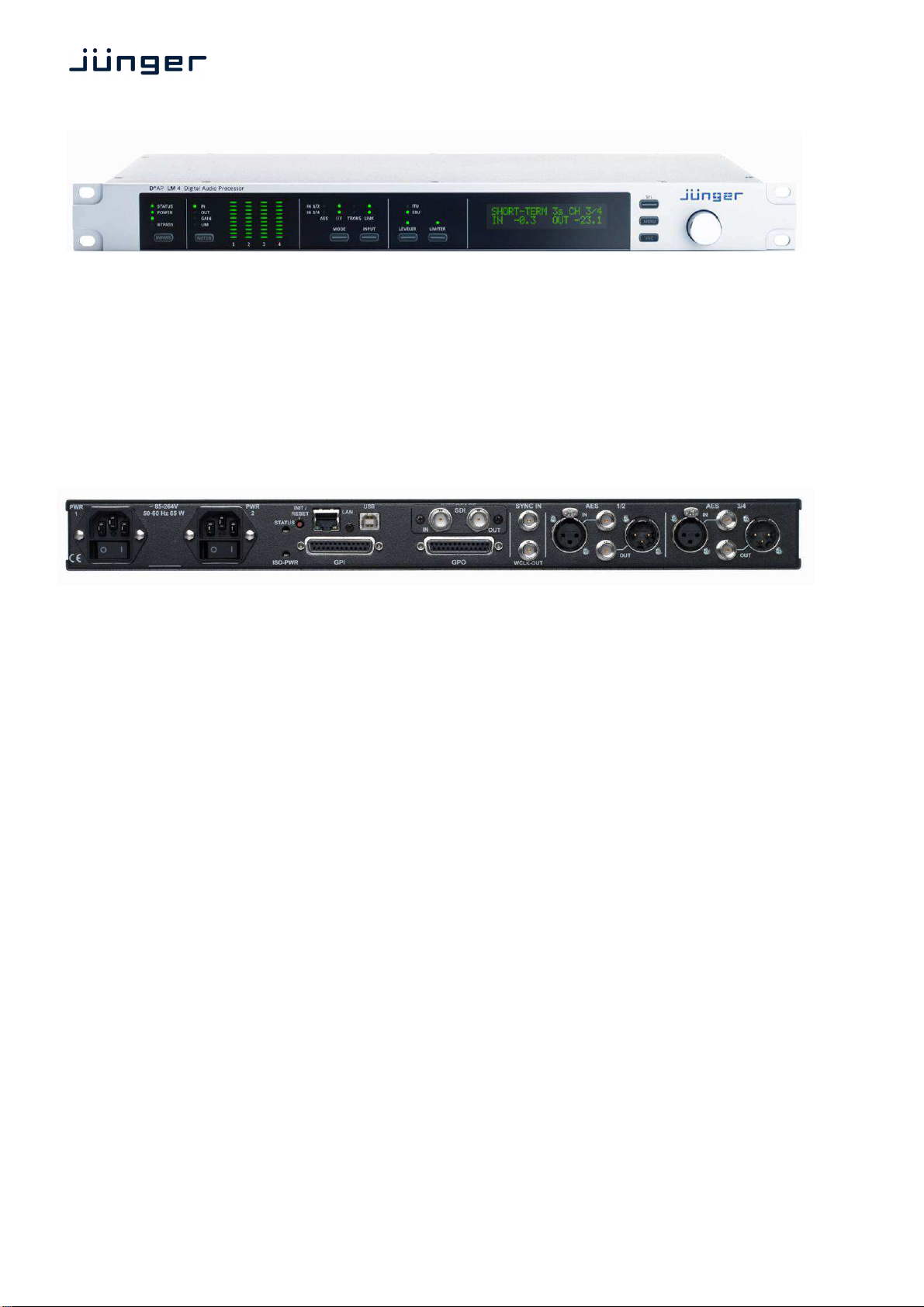
• 1RU compact 19" processing device with front panel
• Front Panel displays 4ch LED bar graph, operating display, LED status display
• Front Panel buttons BYPASS, METER, 4x function control, SEL, MENU, ESC
• Rotary encoder predefined functions, context sensitive modes
• 4 channel audio DSP 2 Analog Devices® Sharc floating point processors
•
2
x AES3 and 2x AES3id on board with independent relay bypass and auto input selection
• 2 x SRC selectable per AES input
• External sync IN 75 Ω input (Word Clock, AES3id, Black Burst, Tri-Level)
• Sync OUT 75 Ω Word Clock output
• RJ45 network connector 100BaseT full duplex Ethernet interface
• USB "B" connector built in USB < > serial adapter to access the device service port
• 8 GPIs balanced inputs on 25pin Sub-D
• 8 GPOs relay change over contacts on 25pin Sub-D
• Aux power supply build in isolated 5 V supply for external GPI/O wiring
• Optional dual power supply load balanced, auto fail over
• One interface slot I/O expansion slot for option modules :
3G / HD / SD SDI module option module 3G SDI de-embedder / embedder with relay bypass
8Ch AES I/O module option module 4x AES3id I/Os with relay bypass
4Ch analog I/O module option module 4x analog line I/Os with relay bypass
8Ch analog out module option module 8x analog line out with relay protection
Rev. 130705
Page 5

D*AP LM 4
page
block diagram ………………………………………………………………………………………. 2
audio processing blocks ……………..……………………………………………………………. 2
getting started .....………………….………………………………………………………………. 3
getting started – IP setup of the device via front panel ………………………………………… 3
getting started – IP setup of the device – via console interface ...……………………………. 4
getting started – IP setup of the device – via web browser ..….………………………………. 5
Operating …………………………………………………………………………………………… 6
Operating – menu structure of the front panel ………………………………………………….. 6
Operating – front panel navigation tree …………………………………………………………. 7
Web GUI ……………………………………………………………………………………………. 8
Web GUI – SYSTEM – Overview ……………………………………………………………….. 9
Web GUI – SYSTEM – Admin …………………………………………………………………….. 10
Web GUI – SYSTEM – Setup …………………………………………………………………….. 12
Web GUI – SYSTEM – The preset concept in detail ………………………………………….. 12
Web GUI – SYSTEM – SNMP ……………………………………………………………………. 13
Web GUI – SYSTEM – Backup / Restore ……………………………………………………….. 13
Web GUI – SYSTEM – Software Update ……………………………………………………….. 14
Web GUI – SYSTEM – Reboot …………………………………………………………………… 14
Web GUI – SYSTEM – System Status …………………………………………………………… 15
Web GUI – INTERFACES – AES I/O ……………………………………………………………. 16
Web GUI – INTERFACES – SDI I/O Interface – De-Embedder ……………………………… 17
Web GUI – INTERFACES – SDI I/O Interface – Embedder …………………………………. 18
Web GUI – INTERFACES – SDI I/O Interface – Setup ……………………………………….. 20
Web GUI – INTERFACES – (SDI I/O Interface) Status ………………………………………… 21
Web GUI – ROUTING …………………………………………………………………………….. 22
Web GUI – AUDIO PROCESSOR – Overview …………………………………………………. 23
Web GUI – AUDIO PROCESSOR – Setup ……………………………………………………. 23
Web GUI – AUDIO PROCESSOR – Input ………………………………….......................... ... 24
Web GUI – AUDIO PROCESSOR – Fail Over ……………………………………………….... 25
Web GUI – AUDIO PROCESSOR – Filter – Spectral Signature ……………………………… 26
Web GUI – AUDIO PROCESSOR – Filter – Equalizer ………………………………………… 27
Web GUI – AUDIO PROCESSOR – Dynamics ………………………………………………… 29
Web GUI – AUDIO PROCESSOR – Voice Over ……………………………………………… 30
Web GUI – AUDIO PROCESSOR – LevelMagic™ …………………………………………….. 32
Web GUI – AUDIO PROCESSOR – Output …………………………………………………..... 34
Web GUI – EVENTS – Trigger – Trigger Configuration ………………………………………. 34
Web GUI – EVENTS – Trigger – Remote Hotkey Sources …………………………………… 35
Web GUI – EVENTS – Trigger – Network Sources ……………………………………………. 36
Web GUI – EVENTS – Trigger – Parameter Sources …………………………………………. 37
Web GUI – EVENTS – Events – Preset Events – System …………………………………….. 37
Web GUI – EVENTS – Events – Preset Events – Interface …………………………………… 38
Web GUI – EVENTS – Events – Preset Events – Routing ……………………………………. 38
Web GUI – EVENTS – Events – Preset Events – Audio Processor ………………………….. 39
Web GUI – EVENTS – Events – Action Events – GPO ………………………………………… 39
Web GUI – EVENTS – Events – Action Events – Loudness Measurement ………………… 40
Web GUI – EVENTS – Events – Bypass Events ………………………………………………. 41
Web GUI – EVENTS – Events – Example Setup ………………………………………………. 42
Technical data …………………………………………………………………………………...... 44
Technical data – base unit rear connectors – pin assignment ……………………................. 45
Technical data – interface modules – SDI De-Embedder / Embedder [SDI 150] ………… 46
Technical data – interface modules – 4x AES I/O [DD 188] ………………………………… 47
Technical data – interface modules – 4x analog I/O [AN 144] ………………………………. 47
Technical data – interface modules – 8x analog I/O [AN 104] ………………………………. 47
Technical data – optional interface modules – pin assignment ………………………………. 48
safety information …..……………………………………………………………………………… 49
warranty …………………………………………………………………………………………….. 49
Content
1
Page 6
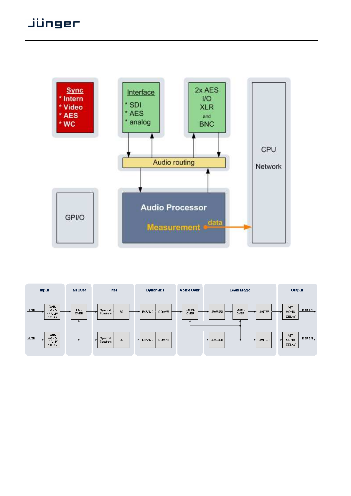
Block diagram :
D*AP LM 4
Audio processing blocks :
2
Page 7

D*AP LM 4
Getting started
Communication with the LM 4 is via TCP/IP over Ethernet and each unit is shipped with a default IP address.
Before the unit can be controlled, the following steps are required:
1. Obtain a unique IP address for the network onto which it will be installed.
2. Overwrite the default IP address with the new one by one of the methods below.
3. Ensure that the computer has an upto date version of Java installed and that any firewall is configured to
allow UDP data to be returned to the unit
For specific advice, please consult your network administrator
Getting started – IP setup of the device via front panel
After power up the front panel shows the idle display:
SHORT-TERM 3s CH 1/2
IN -70.0
Now you must press <MENU>. This will show HOTKEYS menu entrance. Now turn the Rotary Encoder
[RE] one turn left and you reach the CONFIG menu. Press the <RE> and the menu item NETWORK will be
displayed. Press <RE> again and you will enter the network setup :
OUT
-70.0
IP
10. 110. 3. 73.
If you turn the RE to the right, you may select between IP, MASK and GATEWAY. If you press the <RE> now
you will enter the setup display of the respective item.
Flashing arrow markers (cursors) will appear in one of the fields, to indicate that you may change this value
by turning the RE. Below an example for the IP address:
IP
>10<
Pressing <SEL> will move the flashing cursors to the next address field(s). After performing the setup you
must press <MENU>.to apply the changes:
110. 3. 73.
IP CONFIG CHANGED
OK : APPLY ESC : DISCARD
Pressing <RE> will store the changes and will reboot the device in order to apply and use it.
APPLYING CHANGES
REBOOTING . . .
3
Page 8
D*AP LM 4
Getting started – IP setup of the device via console interface
The tool to change the IP configuration of the device will be reached via the console interface. You must
connect the LM 4 with the PC via an USB A to B cable. Before connecting the cable you must have the
FTDI driver installed on your PC. You will get it from the Co web site:
http://www.ftdichip.com/FTDrivers.htm
You must go for the VCP (Virtual Com Port) Drivers section and select the "setup executable" that matches
your PC processor. E.g. "CDM20814_Setup.exe". Download the file and run it.
This will install the driver for the built in USB to serial converter. Now you can connect the cable and open a
terminal program. Here you must select the virtual COM port assigned by the OS. The communication
parameters are:
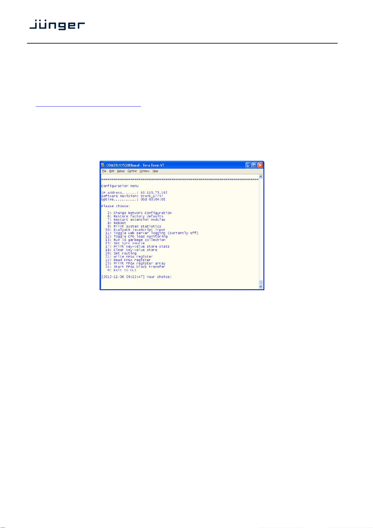
115200kBaud, 8, N, 1 no hand shake. Pressing <ENTER> will open the console menu:
Go for item 2 and press <ENTER>:
"Your choice: 2"
"Current network configuration
IP Address : 10.110.24.128
Netmask ... : 255.255.0.0
Gateway ... : 10.110.0.1
You must enter the IP address and the netmask.
Enter new IP address, press ENTER to cancel: "192.168.176.78" <Enter>
Enter new netmask, press ENTER to cancel: "255.255.255.0" <Enter>
Important Note! The gateway entry is optional but you must take care that the gateway address is matching
the network mask related to the device IP address!
If you’re not sure simply enter 0.0.0.0.
Enter new gateway, press ENTER to configure without gateway: "0.0.0.0" <Enter>
Network configuration has been changed. Please reboot the device
To activate the new settings.
Select item 8 and press <ENTER>:
Do you want to reboot the device?
Press small "y“:
Do you want to reboot the device? y
Press <ENTER>
Rebooting the device ……..
After reboot has finished the new IP configuration is active.
4
Page 9
D*AP LM 4
Getting started – IP setup of the device via web browser
* Read the default IP address printed on a label between mains sockets.
* Set up network parameters of the PC which meet the default IP address of the LM 4
(net mask = 255.255.0.0).
* Connect the device with the PC either by an Ethernet cross over cable or by a switch.
* Open a browser and type the device IP address into the URL field and press <ENTER>.
This will open the AUDIO PROCESSOR >> Overview pane of the GUI.
* Click on SYSTEM and the "Admin" pane will open automatically:
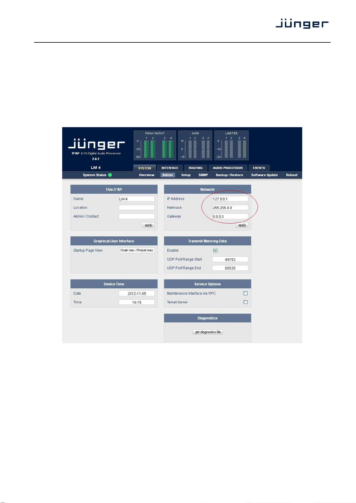
Enter the desired network configuration into the marked area and press <apply>
Afterwards you must reboot the device in order to activate the new IP configuration.
Regarding Gateway address see above.
Important Note! After reboot the web browser may not be able to communicate with the LM4. You must key
in new IP address in the URL field.
5
Page 10

D*AP LM 4
Operating
Operating – menu structure of the Front Panel :
The display after power up – the idle display – shows the input "IN" and output "OUT" short term (3secs.)
loudness of the programs processed by the respective device channels. E.g.:
If you turn the RE the display will change to the True Peak Hold display of the respective channels:
And vice versa. If you press <SEL> you will see the values of the other processing channels.
Pressing <ESC> will reset the display reading (HOLD reset).
The 4 direct function buttons of the front panel will move you to the respective function blocks
where the RE selects the respective items.
The overall parameter menu structure is shown on the next page.
SHORT-TERM 3s CH 1/2
IN -70.0
TRUEPEAK-HOLD
IN -70.0
<MODE> LOUDNESS MODE > SYNC SOURCE
< MUTE < ENABLE < LINK
<INPUT> INPUT GAIN > MONO > HP FILTER > LP FILTER > DELAY >
INPUT ROUTING BIT TRANSPARENT
< LINK
<LEVELER> ENABLE > LOUDNESS TARGET > TIME > MAX GAIN >
FREEZ LEVEL > TP MAX GAIN > TP RESPONSE > PROCESSING >
CLEAR HISTORY > INITIAL GAIN > THRESHOLD
<LIMITER> ENABLE > MAX TRUE PEAK > PROCESSING
OUT
OUT
-70.0
CH 1/2
-70.0
6
Page 11
D*AP LM 4
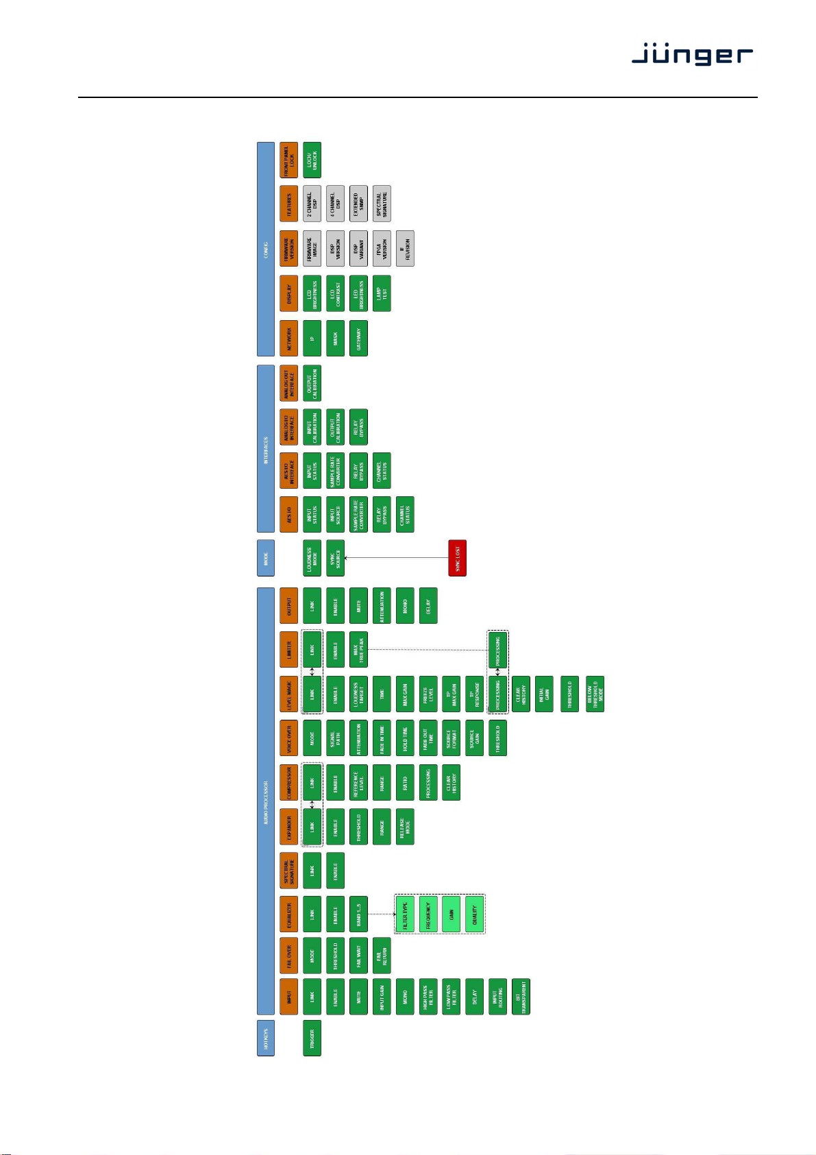
Operating – front panel navigation tree :
7
Page 12
Web GUI
Type the device IP address into the URL field of a browser to display the initial web page
of the D*AP-LM4 :
D*AP LM 4
The default view is a general block diagram of the audio processing section.
Firstly you must set up basic things such as program configuration, give the programs meaningful names and
set the synchronization source. You may also give the device a name, tell it its location and define an
administrative contact which may be used by monitoring systems of your house (e.g. via SNMP).
Selecting any of the top 5 tabs (SYSTEM, INTERFACE, ROUTING, AUDIO PROCESSOR, EVENTS) will
reveal a second row of options specific to the chosen tab.
The following paragraphs will guide you through the set up of the LM 4 step by step.
8
Page 13
D*AP LM 4
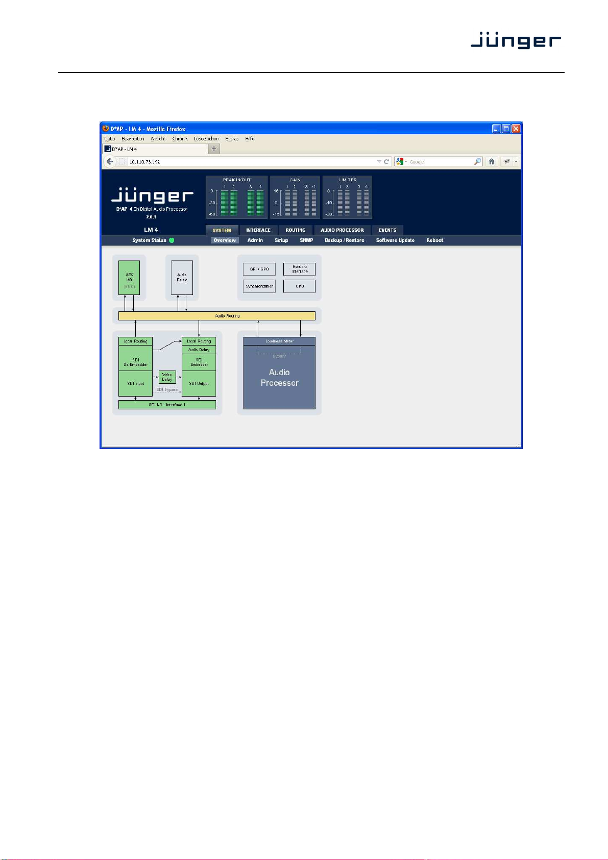
Web GUI – SYSTEM – Overview
The graphical overview shows the main building blocks of the device including the options installed such as a
SDI interface module.
You may click into the boxes and the respective page will open. The navigation is based on URLs so you may
use the <Back> navigation button of the browser to return to this page.
9
Page 14
D*AP LM 4
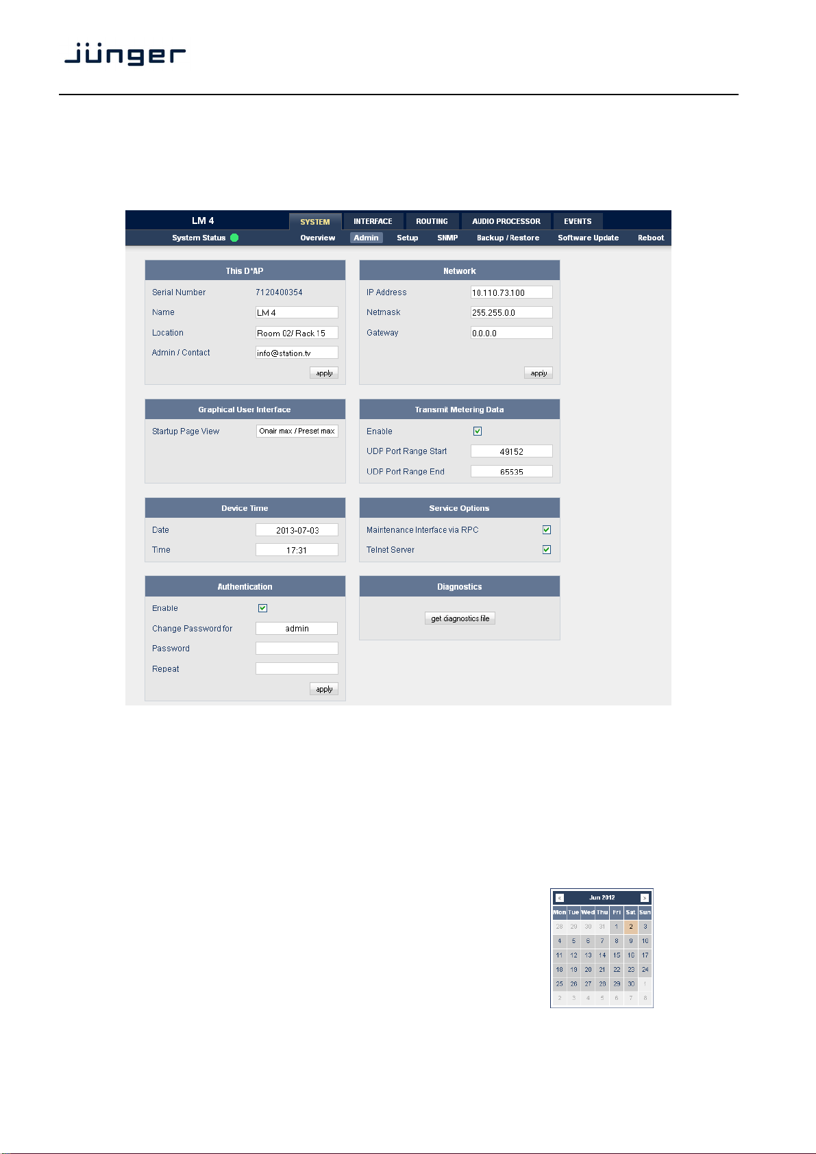
Web GUI – SYSTEM – Admin
Admin – allows for the setting of global options including device name and time, network and remote service,
diagnostics and start up page view of the preset editor.
This D*AP input fields for information utilized by higher level services.
Name give the device a meaningful name that may be used by name services
Location the place where the LM 4 is located
Admin / Contact e-mail address of a person in charge.
and SNMP management.
Graphical User Interface defines the appearance of the parameter panes regarding preset editor
and on air parameter visibility (see below – for preset concept).
Device Time allows you to set the device clock. At the factory it is set to
UTC (Coordinated Universal Time).
Date if you click into the Date input field,
a comfortable calendar tool will pop up :
Time if you click into the Time input field,
you will be able to set the device time.
10
Page 15
D*AP LM 4
Authentication to prevent non authorized people from changing device settings the
Enable [enable / disable]
the administrator may turn authentication off.
Change Password for [admin / operator]
Select which password you will set / change
Password key in a password
Default passwords are: admin (for admin) and operate (for operator).
Repeat repeat that password
Important Note! The authentication may be enabled / disabled form the console interface as well
(see page 8 "1: Manage Password") via USB connection but also via Telnet! If you have higher security
demands you should turn the Telnet server off. Authentication will turned off and passwords will be reset if
one initializes the device to factory default (see Reboot - page 19, INIT/RESET rear button - page 4).
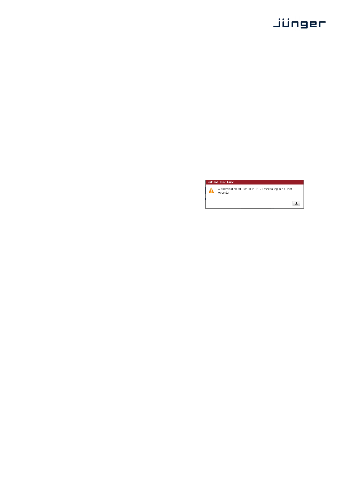
If there was an authentication failure, the admin
will be notified on next proper login about such conditions :
The pop up appears as often as an login failed.
Network IP address setup, see above: "Getting started – IP setup of the device via web browser"
IP Address
Netmask
Gateway
Transmit Metering Data metering data will be streamed via UDP protocol. In order to receive such
Enable streaming of metering data via UDP on demand of an external application
UDP Port Range Start lowest port number.
UDP Port Range End highest port number.
an external application, that can not be configured prior to start up like the
Other applications like the J*AM which have pre definitions will not ask the
Service Options
Maintenance Interface
via RPC for in house use to enable communication with factory tools.
Telnet Server enables a telnet server to connect the consol interface via IP (port 21).
Diagnostics
get diagnostics file pressing this soft button will start the assembly of a diagnostics file.
administrator may assign passwords for either the admin and/or an
operator (same applies for talent/artist). While the admin is allowed to set
everything, an operator is just allowed to load presets. Parameters will be
reset if there was an attempt from the operator to change it.
data by external applications you must define ports (port range) for
matching fire wall definitions.
(web browser, J*AM, 3rd party).
web GUI will ask the LM 4 for the possible port range and will start looking
if the first port is available on the PC where the application resides. If yes it
will tell the LM 4 to start streaming on that port.
If not the application must look for next available port.
LM 4 for possible UDP port range. They will use the one from the
application set up menu.
The file will be presented in XML format for download.
If you experience unexpected behavior of the device you may be asked by
the Junger service team to send such file by e-mail for analysis.
11
Page 16
D*AP LM 4
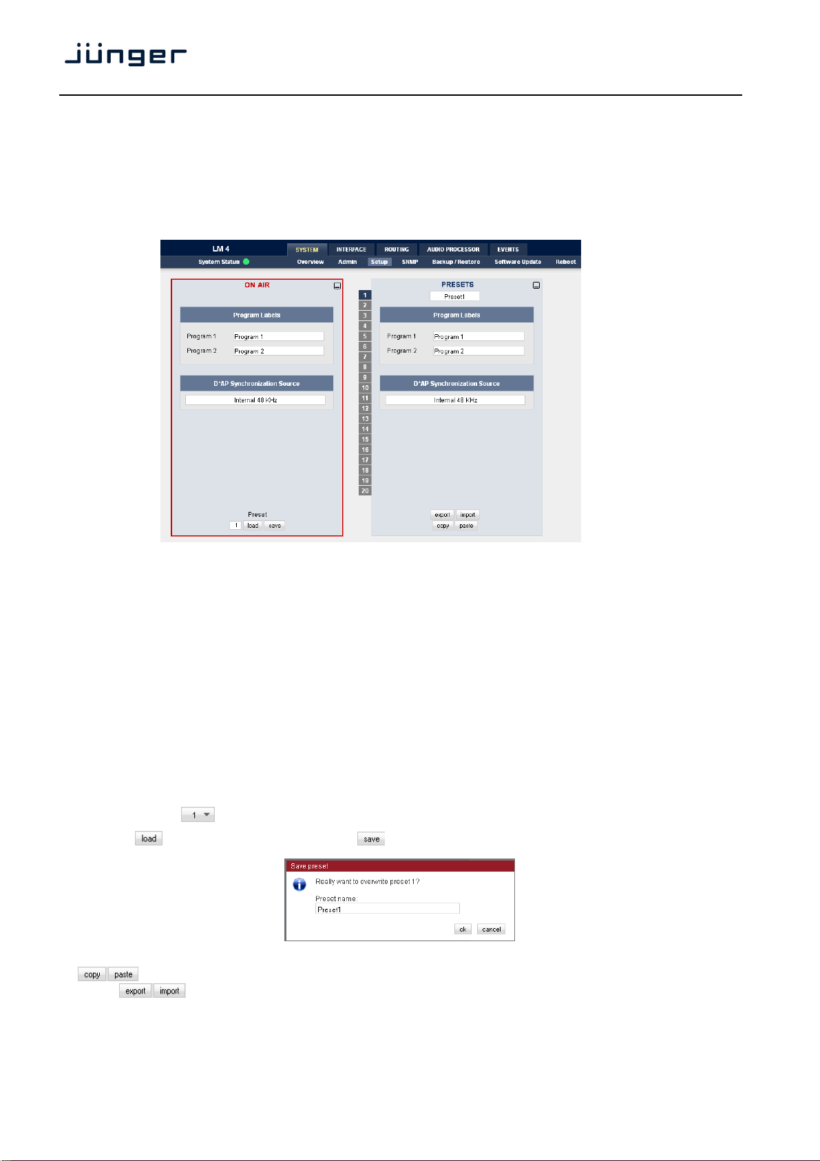
Web GUI – SYSTEM – Setup
Setup – Allows the editing of program labels for the 2 stereo input sources along with the sync source
selection. Displayed to the right is the PRESETS window which is common to many of the set up screens.
Presets allow for up to 20 different parameter settings that can recalled when desired.
Program Labels each of the individual programs has a name that will be used as a
reference for the display of parameters and its setup.
D*AP Synchronization Source with this pull down you may select between the available sync
sources :
Internal 48kHz, External AES, Input AES 1/2, External WCL,
Interface (if an option board is installed),
Black Burst / TriLevel).
Web GUI – SYSTEM – The Preset concept in detail
The example above shows the preset concept of the LM 4. It is the central theme of the device.
For all relevant setting of the device one set of ON AIR parameters and 20 sets of PRESETS are available If
you want to load parameters from a preset or save parameters from the ON AIR area
to a preset, you must first select a preset number at the bottom of the ON AIR page.
You must press to open the pull down list to select the desired preset.
Pressing will execute it. When you press , you will be asked in a pop up :
to overwrite the selected preset and to give it a (new) name.
acts as a clip board for the parameters of individual presets,
while will allow you to store / recall the set of 20 presets to / from the PC file system.
Important note! The presets of the LM 4 are persistent by nature. You are working directly on the preset
memory, i.e. you must not worry about storing such presets. The LM 4 does it for you.
12
Page 17
D*AP LM 4
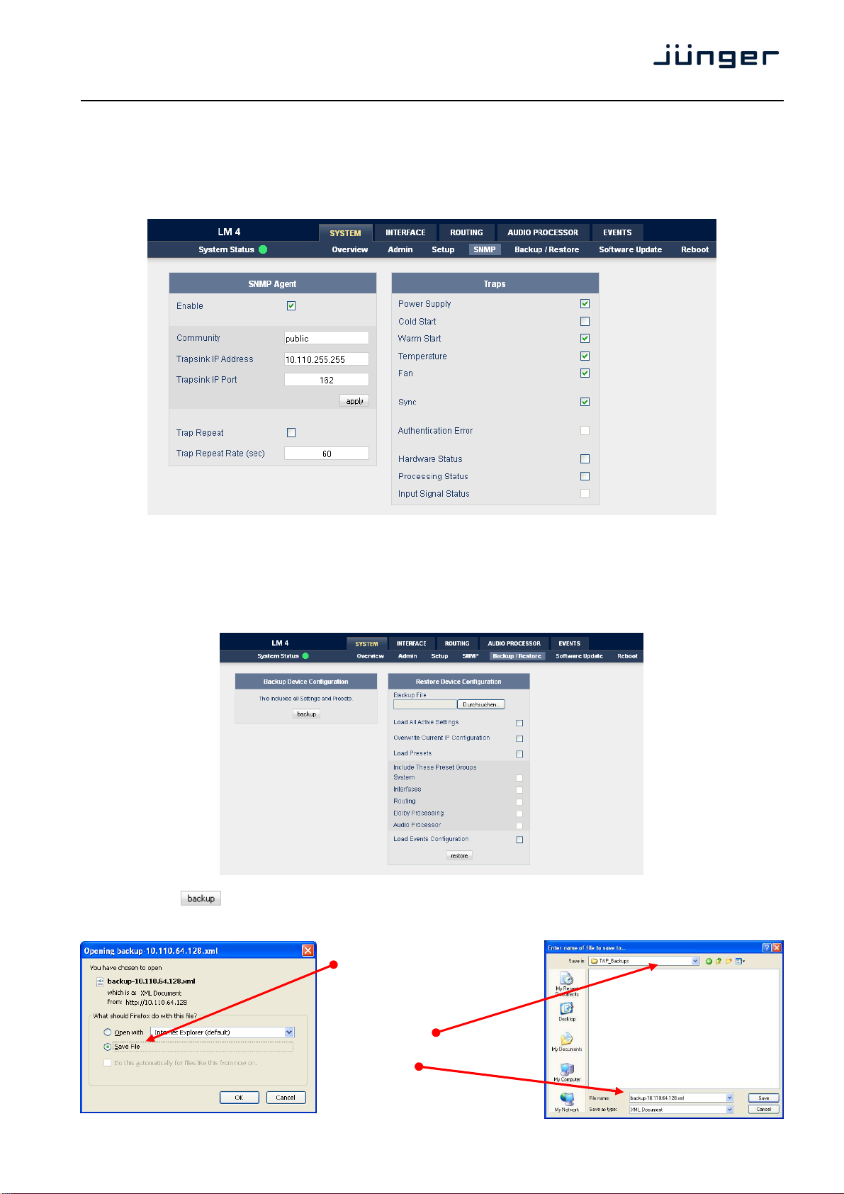
Web GUI – SYSTEM – SNMP
SNNP – Here you can set up the Simple Network Management Protocol options including alarms and
notification path. You may also select what kind of Trap the LM 4 must send in case of emergency.
Web GUI – SYSTEM – Backup / Restore
Backup / Restore – All device settings and parameters can be either backed up for future recall, or restored
from a previously created backup file.
If you press the device controller will collect all necessary data and assemble it to an XML file. Finally
you will get a pop up message:
You must select :
<Save File>.
After pressing <OK>, the
system file dialog opens :
Select a folder
and alter that default file name
if needed.
13
Page 18

D*AP LM 4
Web GUI – SYSTEM – Software Update
Software Update - The files to update the LM 4 will be available in ZIP format. You must unpack it to your
PC in order to access them for the update procedure.
You will find an image file for the LM 4 core system in the format: "rel_lm4_x_y_z.img"
as well as update files for components, like the optional interface boards
in the format: "rsdi150_v47.sdi".
To update the LM 4, you must <Browse …> for the respective
Firmware File(which you have unzipped before) and press .
After finishing the procedure the device will reboot.
You may also update the firmware of an SDI board installed in one of the
two interface slots (or both). The example above shows one SDI I-O board installed into
interface 1 slot. You must select the appropriate file from the firmware update bundle (ZIP file)
and press afterwards.
The LM 4 has a few options you may buy extra. Which option is active on your device you can read from
the licensing display in the bottom right part of this page. If you buy a license later on you must save the
"license info" file and send it to your dealer. After purchasing the option you will get a "license" file in return
which you must apply from there. After rebooting the device the license becomes active.
Web GUI – SYSTEM – Reboot
Reboot – Following changes to the set up or configuration, a reboot may be required. Two additional
options allow for restoring the factory default settings and overwriting the current network IP settings if they
have been changed.
14
Page 19

D*AP LM 4
Web GUI – SYSTEM – System Status
System Status – Provides a current overview of critical system parameters including device, processing and
interface status along with a system log and any system messages.
Device Status provides the hardware status of the LM 4
Power 1 status of the first power supply (left hand side from rear)
Power 2 (optional) status of second power supply (right hand side from rear)
Temperature measured on the surface of the main PCB
Sync Lock turns red if the external sync source is removed or unstable
Processing Status
Bypass turns red if Bypass is activated
Interface Status
AES I/O turns red if an AES input that is internally in use (i.e you have routed it to
an input of a function block) has detected an error
SDI I/O Interface turns red if the SDI input is not locked (no or bad SDI signal)
15
Page 20

D*AP LM 4
Web GUI – INTERFACE – AES I/O
AES I/O – Allows the set up of AES input source selection along with a display of signal input status.
Input Status each AES input has a status detection that may show :
PCM or Fail (no carrier, unlock, cranky [too much jitter]).
If one of the inputs is not assigned by the ROUTING section, its
status will not be incorporated into the System Status.
Input Sample Rate Converter for asynchronous sources it is possible to turn a SRC on per input. If
a SRC is turned on and the input status becomes Non-PCM, the
respective SCR will be turned off automatically in order to maintain
AES Relay Bypass the power fail bypass relays of all 2 I/Os may be activated manually.
the original data structure of an encoded bit stream like Dolby E.
Output Channel Status the channel status can be either
transparent from the input source
of the LM 4 or may be overwritten.
The pull down offers these options :
16
Page 21

D*AP LM 4
Web GUI – INTERFACE – SDI I/O Interface – De-Embedder
SDI I/O Interface – Here the options for de-embedding, embedding and SDI set up are performed.
The De-Embedder selects routing of all 16 channels to the audio processor block.
There is a 16 x 16 matrix to allow for any combination of audio signals to be presented to the LM 4 because
inside the LM 4 the signal routing is oriented in pairs. I.e. the label "SDI 1/2" represents two audio channels
selected by the matrix :
17
Page 22

Web GUI – INTERFACE – SDI I/O Interface – Embedder
Whilst the embedder selects routing from the audio processor block to the output.
D*AP LM 4
18
Page 23

D*AP LM 4
Video Delay For compensation of any kind of audio processing delay within the chain of
Generate new SDI If there is the need to replace the structure of the Ancillary Audio
Audio Structure Data Blocks you can clean the whole area and generate a new structure.
SDI Out Grx This check box enables each of the 4 SDI audio groups to be used
Silence Mutes the respective audio channel on the embedder side.
Delay The inputs of the embedder routing matrix can be taken either
from the de-embedder or from the LM 4 in any combination. If they are
For signals coming from the LM 4 routing an independent delay per
Channel Status Bits For the signals coming from the C8k audio busses, you can decide
Transparent whether the AES Channel Status Bits are taken from their source or if
In this case the Channel Status will be set to:
Important note! If you generate a new AES channel status the Audio Mode will be automatically set to
Non Audio for both channels, if an adjacent pair (1/2, 3/4 …..) carries a Dolby E stream for example.
devices you may use a Video Delay.
Position “0” turns off the delay function.
If the option is checked, there will be no signal available at the group
output as long as no SDI Out Grx is checked.
individually by the embedder. If it is not checked and
“Generate new SDI Audio Structure” is not enabled, the audio data from
the input will travel untouched from the SDI input to the output.
taken from the de-embedder and a Video Delay is introduced, the time of
that Video Delay will be automatically compensated for those signals.
single channel may be used.
you want to generate new ones.
Format : Professional
Audio Mode : Audio / Non Audio
Emphasis : None
Freq. Mode : Locked
Sample Freq. : 48kHz
Channel Mode : Not Indicated
User Bits : None
Auxiliary Bits : 24Bit
Audio Word Length : Not indicated
19
Page 24

Web GUI – INTERFACE – SDI I/O Interface – Setup
D*AP LM 4
Relay Bypass will deactivate the Bypass Relay. It provides a shortcut from
SDI-IN to SDI-OUT1 and disconnects the de-embedder
from the SDI input. This relay also serves as a fail bypass if the power is
off. This feature maintains the SDI signal for downstream equipment.
SDI Bypass will pass the embedded audio data from the de-embedder
to the embedder 1:1. This function preserves the original
Ancillary Data structure.
Stream Select (3G-B) a 3G-SDI signal may have two HD substreams (e.g. for 3-D TV),
AKN as 3G-B standard. The radio buttons select between
stream 1 or 2 for embedded audio. See SMPTE 425M for details.
Generator enabled The video generator may be enabled here. The video format it generates
depends on the selection below.
Test Pattern If the Generator is on, it will generate one of the two video test patterns,
either black or 100% color bar.
Video Format If the Automatic mode is selected and the Generator is enabled, it turns
on if the SDI input signal fails. In this case it will generate the same video
format as the previous input signal.
If “Generator enabled” is checked and if you have selected one of the
Video Formats the Generator will be turned on using this format.
Important note! If the generator is on, either in manual or in automatic mode, it operates on an
internal quartz reference. It is not possible to genlock it to an external reference or to the SDI input.
20
Page 25

D*AP LM 4
Web GUI – INTERFACE – SDI I/O Interface – Status
Status – Indicates the current status major SDI settings and parameters.
Video Standard display of the video standard detected by the SDI input.
SDI Bypass turns yellow if the SDI bypass function is activated.
Relay Bypass turns yellow if the power fail relay is deactivated manually.
Test Generator Active turns yellow if the Generator is turned on.
Video Delay Enabled turns green if the video delay is activated.
De-Embedder Audio Status is grey if no audio is present
turns green if PCM audio is embedded
turns yellow if a non audio signal is present, an additional label shows
ARIB B39 meta information standard.
Data Available turns green if ARIB B-39 meta information are detected.
Block Error turns red if an error has been detected.
the kind of signal if it is possible to gather the information.
Audio Mode see ARIB Japanese standard "Structure of Inter-Stationary Control
Data Conveyed by Ancillary Data Packets" :
http://www.arib.or.jp/english/html/overview/doc/2-STD-B39v1_2.pdf
21
Page 26

Web GUI – ROUTING
This tab is used to setup the routing path of the audio signal(s) through the unit.
D*AP LM 4
Each functional block of the device has an input- and an output-label. The output-labels are pre-defined,
while the label of an input must be selected by the administrator in order to route the signals.
Additional blue labels give an indication of the type of signal that is expected by the respective function block
input (e.g. 1L/1R for the DSP).
The above screen shot shows an example configuration :
DSP the de-embedder outputs [SDI 1/2 and 3/4] are connected to the
DSP 1/2 [1/2] and 3/4 [3/4] inputs.
After processing by the DSP, these signals will leave it at the outputs
DSP 1/2 to 3/4.
AES the first outputs AES 1/2 is connected with DELAY 1/2 for a parallel
delay line, while AES 3/4 is not connected.
Delay a signal pair from the AES 1/2 input will be delayed
by 150ms and is available for routing by using the label DELAY 1/2.
Interface 1 SDI I/O DSP 1/2 and DSP 3/4 are both connected with the embedder input
EMB 1/2 and EMB 3/4.
Where these signals will be embedded must be defined on the
respective setup pane :
INTERFACES > SDI I/O Interface > Embedder.
22
Page 27

D*AP LM 4
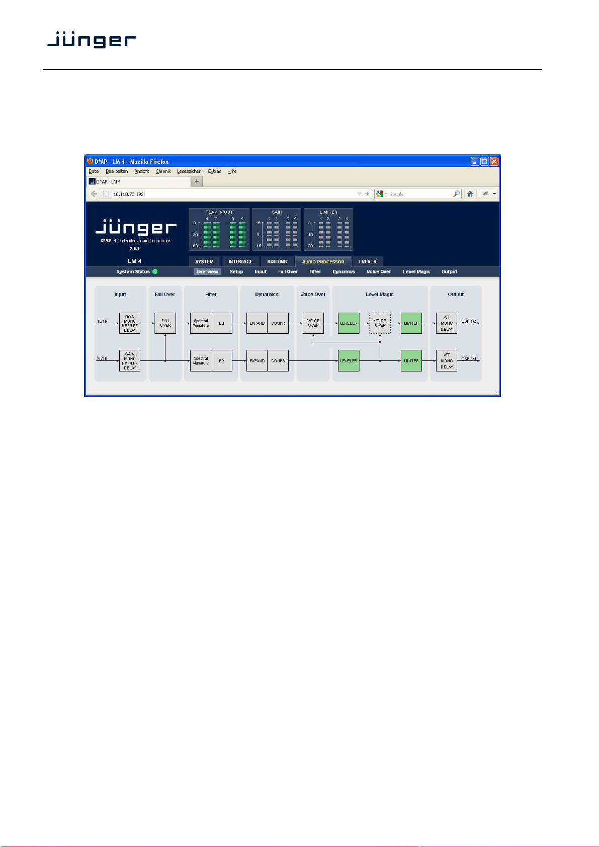
Web GUI – AUDIO PROCESSOR – Overview
The overview shows the actual signal routing of the audio processor blocks, rendered by the DSPs.
This overview depends on the program configuration of the LM 4.
The overview shows all available function blocks. The function blocks which are activated for actual
processing are highlighted by green color.
Web GUI – AUDIO PROCESSOR – Setup
23
Page 28

D*AP LM 4
Loudness Control Mode the pull down offers the selection of these algorithms for the
LevelMagic™ process as well as for the loudness measurement :
Level the Jünger Audio proprietary level based algorithm to achieve the
ITU-BS.1770-1 defined by the ITU and found in ATSC standard A/85:2011
ITU-BS.1770-2 enhanced ITU standard
EBU R128 defined by EBU-TECH 3341. Became the de facto standard for
Processing Bypass will deactivate all predefined processing parameters. Which parameters
Latency Management forcing minimal latency (= ON) reduces the roundtrip delay of the unit
Bit Transparency ON will physically bypass the audio signals related to the labels on the left
Web GUI – AUDIO PROCESSOR – Input
same program level for different programs.
loudness based level control and metering in TV broadcast.
are bound to the Processing Bypass function must be defined in the
EVENTS section. The audio signals still travel through the DSP but they
are not processed.
down to
4 milliseconds. This is only valid if Spectral Signature is disabled in both
programs. This function will be activated for the next release.
hand side. This function preserves the integrity of such signals if they
appear in a signal path
In case of AUTO the channel status will be observed and if Non Audio
is detected bit transparency will be enabled.
24
Page 29

D*AP LM 4
Link [Linked / Unlinked]
defines the coupling of the control circuits in order to maintain the
Input [Enable / Disable]
here there are numerous pre-conditioning options for the input audio
Mute will mute all channels controlled by the respective column.
Input Gain (dB) sets the gain [-80 … +20]
Input HPF (Hz) high pass filter (6dB/oct) cut off frequency [OFF, 2, 20, 40, 80, 120]
Input LPF (kHz) low pass filter (6dB/oct) cut off frequency [OFF, 15, 20, 22]
Input Delay (ms) [1 … 2000]
listening balance for correlated signals and to provide a grouping of the
setup parameters for two channel signals.
signal(s).
Web GUI – AUDIO PROCESSOR – Fail Over
Fail Over – Set the conditions for detecting loss of main audio in order to trigger switching to the secondary
source.
For the program input 1L/1R, the source for the fail over circuit can be the second program input
(input 2L/R). The Mode switch will select the respective signal path.
Fail Over 1L/1R
MODE The Fail Over output can be permanently connected to :
its program input 1L/1R
the second program input 2L/2R
or may be set to AUTO
25
Page 30

Fail Threshold (dBFS) [-80 … -40]
RMS weighted input level for fail detection.
Fail Wait (s) [1.5 … 10.0]
elapsed time after fail detection until the switch over will happen.
Fail Return (s) [0.0 … 10.0]
elapsed time after detection of a proper input signal until the switch
back to the program input.
Side Chain Filter [OFF / ON]
a high pass filter (300 Hz) and a low pass filter (3000 Hz) is applied
to the detector side chain (not the audio path) to prevent hum and
noise from blocking fail over switching.
Web GUI – AUDIO PROCESSOR – Filter – Spectral Signature
Two options are available to modify the audio signal(s) :
AUDIO PROCESSOR – Filter – Spectral Signature
D*AP LM 4
Link [Linked / Unlinked]
Spectral Signature [Enable / Disable]
is a dynamic multi band filter that allows precise control of the audio
spectrum. It is useful in order to create a unique “signature sound” for
audio broadcast.
Note that this feature requires the appropriate license and the additional J*AM Jünger Application Manager
software to be installed separately.
The application manager may be downloaded from the Junger website :
www.junger-audio.com/download/soft-firmware/JungerApplicationManager_a.b.cdefg.zip
For details how to operate the J*AM, pls. also see separate manual :
http://www.junger-audio.com/uploads/media/JAM_manual_yymmdd.pdf
26
Page 31

D*AP LM 4
For devices which have the license and for programs which are enabled for this feature you will get
If you highlight a program that is enabled for Spectral Signature the soft button
<Spectral Signature> becomes active.
When you press the soft button this window shows up on the PC screen :
The process must be enabled in order to get the correct display. You can do it either from the LM 4
GUI or from here. When starting this application the settings will be read from the LM 4
and will be used and displayed here. Pay attention that Max Gain is not set to 0dB.
If you change settings you must store them in the LM 4 by first selecting a preset number and pressing
the <save> button in the ON AIR section of the Spectral Signature pane afterwards.
27
Page 32

D*AP LM 4
AUDIO PROCESSOR – Filter – Equalizer
Equalizer gives access to a 5 band Parametric EQ that can be adjusted independently for each audio
input program.
Link [Linked / Unlinked]
Equalizer [Enable / Disable]
Band 1
Filter Type [OFF, Lo Shelf, Peak, Hi Shelf]
Frequency (Hz) [20 … 2000]
Gain (dB) [-20 … +20]
Q [0.4 … 4.0]
Band 2 same as Band1
Band 3 same as Band1
Band 4 same as Band1
Band 5 same as Band1
28
Page 33

D*AP LM 4
Web GUI – AUDIO PROCESSOR – Dynamics
Dynamics – The LM 4 offers a powerful expander/compressor tool that can also be set independently per
audio program source.
Expander [Enable / Disable]
Threshold (dBFS) [-60 … -20]
Range (dB) [0.0 …. 20, Gate]
Release Mode [0 … 9]
simplified EXPANDER curve simplified COMPRESSOR curve
29
Page 34

D*AP LM 4
Compressor [Enable / Disable]
Reference Level (dBFS) [0 … -40]
Range (dB) [0.0 … 20.0, Gate]
Ratio [1 : 1.1 … 1 : 4.0]
Processing [Live, Speech, Pop, Uni, Classic]
Expert [Enable / Disable]
Clear Processing History <clear>
Web GUI – AUDIO PROCESSOR – Voice Over
Voice Over – Allows for the temporary insertion of a secondary audio source whilst attenuating
(or ducking) the primary audio.
30
Page 35

D*AP LM 4
Mode [OFF, Always ON, AUTO]
sets the voice over operating mode
Signal Path [Pre Leveler, Post Leveler]
the position in the signal path regarding the leveler processing block.
Attenuation (dB) [-30 … 0dB]
the attenuation of the program signal in case of active voice over
Timing
Fade In Time (ms) [10 … 1000]
Hold Time (s) [0.0 … 10.0]
Fade Out Time (s) [0.0 … 10.0]
Voice Over Source
Source Format [Stereo, Mono LL, Mono RR, Mono L+R]
the voice feed of the Voice Over circuit is a two channel signal. You
Source Gain (dB) [-20 … 20]
sets the gain for the voice signal prior to mixing.
Threshold (dBFS) [-60 … -40]
the threshold for the voice signal in AUTO mode.
You will also see it in the AUDIO PROCESSOR > Overview sketch,
highlighted in green and surrounded by a solid line that surrounds the
Voice Over processing block in use.
may select here, from which input channel the voice feed will be
taken.
LL for example means the voice signal is taken from the first input
channel and it will be mixed into both program channels. Mono L+R
means that a mono signal is built from a stereo input signal and is
mixed to both (stereo) program channels.
31
Page 36

D*AP LM 4
Web GUI – AUDIO PROCESSOR – Level Magic
Level Magic – Is the proprietary Jünger algorithm used to maintain a constant output loudness irrespective of
the incoming audio levels.
Loudness Control Mode [EBU R 128 / Level / ITU-BS.1770-1 (A/85 2011) / -2 / 3]
Display of the pre selected mode see :
AUDIO PROCESSOR > Setup
Link [Linked / Unlinked]
Note - the limiter an d the leveler link are coupled. From the front
panel you may set it in either function block!
Leveler [enable / disable]
turns off Transient Processor as well.
Loudness Target
Level mode [0 … -50dBFS]
ITU mode [0 … -50LKFS]
EBU mode [0 … -50LUFS]
Time (s/min/h) [10, 20, 40 / 1, 2, 5, 10, 20, 40 / 1, 2]
Max Gain (dB) [0 … 40]
Freeze Level (dBFS) [-20 … -60]
32
Page 37

D*AP LM 4
Transient Processor
Max Gain (dB) [0 … 15]
Response [Soft, Mid, Hard]
Limiter [enable / disable]
Max True Peak (dBTP) [0.0 … -20.0]
Profile (Leveler, Limiter) used by both the leveler and the limiter
Processing [Live, Speech, Pop, Uni, Classic]
Expert [on / off]
The expert mode offers the possibility for manual intervention into
Clear Processing History <clear>
manual or preset controlled
Initial Dynamic Gain (dB) [-40 … 0 … 15]
AGC Recovery [Normal / Fast]
Low Level Behavior
Processing Threshold (dBFS) [-80 … -20]
the threshold from where the processing gain will behave as defined
Below Threshold Mode [Release / Hold]
returns slowly to 0dB gain change or stays at the Processing
For the description of the LevelMagic™ parameters see engineering bulletin :
"LevelMagic-2_Parameters_yymmdd.pdf", which is available for download from our web site.
the adaptive behavior of the LevelMagic process for critical
material. For details pls. see the above mentioned document.
by Below Threshold Mode.
Threshold.
33
Page 38

D*AP LM 4
Web GUI – AUDIO PROCESSOR – Output
Output – The final screen in this section allows for the adjustment of numerous audio parameters directly on
the final output signal.
Link [enable / disable]
Output [enable / disable]
Mute [on / off]
Attenuation (dB) [-80.0 … 0.0]
Mono [Stereo, L+R, LL, RR]
Output Delay (ms) [0 … 2.000]
Web GUI – EVENTS – Trigger – Trigger Configuration
EVENTS - In a broadcast facility, there are often requirements to integrate the Digital Audio Processor into
the automation system in order to facilitate functions such as remotely re-calling presets, firing GPO
commands etc. The events tab is where all relevant parameters can be set up.
A Trigger is the logical combination of up to two trigger sources. The Trigger may launch one or more
events. An event runs like a flip-book inside the D*AP. This powerful technology spans from simply recalling a
certain parameter to the complete reconfiguration of the LM 4. But it also enables several fail over scenarios
where the LM 4 will automatically react to the system and/or parameter status
Trigger – As a default, 8 standard trigger conditions are available. These can be configured to determine
actions resulting from combinations of hotkey, GPI, network commands, parameter values, active events,
other active trigger etc. stimulus :
34
Page 39

D*AP LM 4
At the bottom of the Trigger table we have two icons :
When you click on one of these icons you may add or delete a line of the above table.
When adding a trigger you may give it a name : When removing a trigger you may select it
by its name and press <OK>
Web GUI – EVENTS – Trigger – Remote Hotkey Sources
Remote Hotkey Sources – will assign the hotkeys of the LM 4 names and will enable
the respective key(s) :
The example above shows two activated hotkeys #1 "Gain up" and #2 "Gain down". Which will be used
later for other event configuration:
35
Page 40

D*AP LM 4
Web GUI – EVENTS – Trigger – Network Sources
Network Sources – Allow to set up external trigger sent by an automation system to the LM 4 :
Network trigger are based on the EmBER+ protocol from Co. l-s-b http://www.l-s-b.de/uk
The LM 4 receives such trigger over the TCP/IP network. The triggers are issued by a device that has
implemented the EmBER+ protocol (e.g. VSM server). You may assign these triggers to virtual as well
as physical (e.g. LBP) buttons of a VSM installation. But also a broadcast automation system may have
an EmBER+ client running that may send network trigger to the LM 4
# number of the network trigger
Label label of that network trigger. It appears on the
Trigger Configuration pane as well as in the EmBER+ tree of the
VSM Studio gadget connector.
Below is a screen shot of the VSM gadget connector :
For the Ember tree you must select :
"Device" > controller_dsp > network_trigger > parameters > #.
As a value you will receive the trigger name from the
LM 4 In this example it is the default network trigger name.
36
Page 41

D*AP LM 4
Web GUI – EVENTS – Trigger – Parameter Sources
Parameter Sources – represent the status of selected parameters from selected function blocks :
Label input field for a label of a parameter trigger source
Category [INTERFACES / AUDIO PROCESSING]
Subcategory e.g. If Category = INTERFACES, possible Subcategories are : [SDI
Parameter e.g. if Subcategory = SDI I/O Interface 1, possible parameters are:
Expression 1 e.g. if Parameter = Status, possible expressions are:
The Expression allows multiple values. I.e. you may select [Fail &
I/O interface 1 or AES I/O]
[Status / ARIB B39 Avaialbale / ARIB B39 Block Error/ ARIB B39
Audio Mode / SDI lock]]
[OK / Fail / Not Routed / WARNING].
Not Routed]. In that case both status expressions are marked
green and due to limited space in the pull down the word <multiple
values> will be used
This is a logical or combination. Note that you are able to logical
combine two or all of the expressions of the pulldown no matter if it
makes sense for the actual parameter source!
Expression 2 will be implemented soon
Web GUI – EVENTS – Preset Events – System
A trigger will launch an event. The LM 4 knows four different types of events which may be set up via
page embedded tabs. Firstly we have the System tab :
Because the "SYSTEM" tab has presets only for the "Setup" sub-tab, we have just one column for
recalling systems presets if necessary.
37
Page 42

D*AP LM 4
Web GUI – EVENTS – Preset Events – Interface
For this example a trigger "SDI lost" will launch the event "Relay Bypass". This event will then load
"Preset 5" of the SDI I/O Interface while Preset 5 is set up to turn the SDI bypass relay on.
Web GUI – EVENTS – Preset Events – Routing
Because the ROUTING tab has no sub-tabs we have just one column for recalling routing presets if
necessary.
38
Page 43

D*AP LM 4
Web GUI – EVENTS – Preset Events – Audio Processor
Important Note! The Preset Events tab controls multiple preset categories which are represented by the
page embedded tabs "System!, "Interface", "Routing" and "Audio Processor".
You must be aware that one trigger is valid for an entire line from System over Routing to Audio Processor.
If you change the Trigger on one of the embedded pages it will be changed on all other pages.
Web GUI – EVENTS – Action Events – GPO
Action events – Comprises of two options. Creating GPO control signals, and invoking Loudness
Measurement “Start”, “Stop” and “Pause” commands.
The LM 4 has 8 physical GPO's (relay change over contacts) which may be incorporated into an action
event. The example below will only activate GPO 1 if the "SDI alarm" event is triggered by the SDI lost"
trigger.
Action Events are independent from Preset Events. That is why you must define a new event name
(e.g. SDI alarm). This event should be triggered by the "SDI lost" trigger, which you set up on the trigger
pane (third one) :
39
Page 44

D*AP LM 4
While the source for that trigger is a parameter source :
Web GUI – EVENTS – Action Events – Loudness Measurement
The EBU R128 implements the possibility to start, pause / continue, reset a loudness measurement.
The example above defines two action events "Start" and "Stop". They will be triggered by :
"Start Loudness Measure" and "Stop Loudness Measure" which have been setup
previously on the trigger pane :
While the source for those two triggers are GPI #1 and #2
40
Page 45

D*AP LM 4
Web GUI – EVENTS – Bypass Events
Bypass events – The final screen allows the configuration of event sequences that will happen in the case of
loss of input audio or selected forced bypassing of audio processing parameters.
The LM 4 has a dedicated <BYPASS> button on the front panel. The function of this button may be
configured in the upper section of the Bypass Events pane.
You may lock the button and you may also control it with the Processing Bypass check box :
The top two rows of check boxes represent the bypass switches of the individual function blocks of the
DSP. They may be used to force the bypass function of individual blocks manually.
If you turn the <BYPASS> button of the front panel ON the Processing Bypass check box will show it.
You may also use this check box to turn the front panel button ON / OFF and the pre-selected "follow"
function blocks will turn on the bypass mode.
In the lower rows you may configure the bypass function of the individual function blocks to be
controlled by an Bypass Events trigger :
The Event named "Bypass Event1" may be triggered by "Trigger 5". It will turn the bypass ON for the
function blocks: Expander, Compressor, and OFF for the Equalizer section.
41
Page 46

D*AP LM 4
Web GUI – EVENTS – Example setup
The way to set up the EVENT system is as follows :
1. Define trigger sources (Remote Hotkey - / Network - / Parameter -)
2. Configure a trigger by logical combination of up to two trigger sources
3. Decide what shall happen by setting up the respective presets which will be used for the events)
4. Assign trigger to event(s)
As an example we will pump up the input gain of the first program by +1dB and reduce it by -1dB.
This should be automatically set by the Omnibus automation system. If the trigger is not set for the actual
event in the run down list, an operator should be able to set it by a remote hotkey …
1. Define trigger sources at the "EVENTS > Trigger > Remote Hotkey Source" pane
we define labels for the first two hot keys :
We also define two network trigger sources for
the automation system on the
"EVENTS > Trigger > Network Source" pane :
2. Configure trigger by logical combination of the hotkey trigger source and the network
trigger sources :
42
Page 47

D*AP LM 4
3. Decide what shall happen we will do this gain change by loading respective presets for the
Therefore we must set up two presets for the input section of
4. Assign Trigger to events because we are about to load presets we must set up
"EVENTS > Preset Events > Audio Processor".
On this pane we select the trigger "Input Gain +1dB"
input section of the audio processor for program 1.
program 1 : Preset 1 = "plus 1dB", Preset 2 = "minus 1dB"
preset events for the audio processor :
and "Input Gain -1dB" respectively and we give these two events the
names "Prog1 Gain up" and "Prog1 Gain down":.
Finally we must assign it the two pre defined presets from the audio
processor input section – that's it :
This is just an example to underline the power of the event management system of the LM 4.
Junger Audio provides you with the tools to support your creativity to deal with events of your interest.
43
Page 48

D*AP LM 4
Technical data
• Power supply optional dual power supply, auto fail over
AC 85 V – 264 V, 50 Hz … 60 Hz
58W max
• AES inputs BNC AES3id, 75 Ω, unbalanced, 24 Bit, 48 kHz, 0.32 … 1.2 Vpp
• AES inputs XLR AES3, 110 Ω balanced, 24 Bit, 48 kHz, 0.3 … 5.0 Vpp
Sample rate converters :
24 Bit, 32 kHz … 192 kHz, THD+N: < 130 dB @ 0 dBFS
Input auto selection :
between AES3id (leading) and AES3
• AES outputs BNC AES3id, 24 Bit, 48 kHz, nominal 1 Vpp @ 75 Ω
power fail relay bypass
• AES outputs XLR AES3, 3.3 Vpp @ 110 Ω
power fail relay bypass
Latency (AES I/O) 323 samples / 6,73 ms @ 48 kHz (all processing blocks active)
Force Minimal
Latency activated 194 samples / 4.04 ms @ 48 kHz (Spectral Signature disabled)
• Sync internal 48 kHz, +/- 10 ppm
• Sync input AES3id: 48 kHz, 0,32 … 1,2 Vpp @ 75 Ohm
Wordclock: 48 kHz, 1 V … 3 V @ 75 Ω
Video: Black Burst or Tri Level, 0.5 V … 1.0V @ 75 Ω
• Sync output Wordclock: 2 Vpp @ 75 Ω
• Network RJ45 rear connector
• USB USB 2.0 "B" build in FTDI USB to RS232 converter
• GPI 5 V – 30 V balanced, auto polarity
• GPO relay change over contacts, 200 mA / 24 V (DC/AC)
• Environmental operating temperature 0 ºC to 50 ºC
Base Unit - fan cooled
non operating -20 ºC to 70 ºC
humidity 90%, non condensing
• Dimensions 19", 1RU, depth 27 cm
• Weight net weight approx. 4 kg, shipping weight 6,5 kg
10/100MBit Ethernet auto sense, full duplex, auto MDI/X
44
Page 49

D*AP LM 4
Technical data - base unit rear connectors - pin assignment
connector :
female 25-pin Sub-D
1 GPI_1a
2
3 GPI_2a
4 GPI_3a
5 GPI_3b
6 GPI_4a
7
8 GPI_5b
9 GPI_6a
10 GPI_6b
11 GPI_7a
12 GPI_7b
13 GPI_8b
14 GPI_1b
15 GPI_2b
16
17
18
19 GPI_4b
20 GPI_5a
21
22
23
24
25 GPI_8a
GPI
Isolated 5V +
Isolated 5V -
connector :
female 25-pin Sub-D
1 GPO_1_NC
2 GPO_1_NO
3 GPO_2_common
4 GPO_3_NC
5 GPO_3_NO
6 GPO_4_common
7 GPO_5_NC
8 GPO_5_NO
9 GPO_6_common
10 GPO_7_NC
11 GPO_7_NO
12 GPO_8_common
13
14 GPO_1_common
15 GPO_2_NC
16 GPO_2_NO
17 GPO_3_common
18 GPO_4_NC
19 GPO_4_NO
20 GPO_5_common
21 GPO_6_NC
22 GPO_6_NO
23 GPO_7_common
24 GPO_8_NC
25 GPO_8_NO
GPO
45
Page 50

D*AP LM 4
Technical data – interface modules – 3G SDI De-Embedder / Embedder [SDI 150]
• SDI input standards (auto sensing)
3G - SMPTE 424/425M (Level A/B)
HD - SMPTE 292M
SD - SMPTE 259M
formats
1080p23.98, 24, 25, 29.97, 30, 50, 59.95, 60
1080i50, 59.94, 60
720p23.98, 24, 25, 29.97, 30, 50, 59.94, 60
625i50
525i59.94, …
connector
BNC IEC 169-8)
75 Ω
return Loss
> 15 dB (typ. > 18dB) from 5MHz to 1485 MHz
> 10 dB (typ. > 11 dB) from 1485 MHz to 2970 MHz
adaptive equalization, typical of Belden 1694A coaxial cable
250 m at 270 Mbps
250 m at 1.485 Gbps
150 m at 2.97 Gbps
jitter tolerance
Timing: > 2UI, Alignment: > 0.7 UI
• SDI output standards
3G - SMPTE 424/425M (Level A/B)
HD - SMPTE 292M
SD - SMPTE 259M
formats
1080p23.98, 24, 25, 29.97, 30, 50, 59.95, 60
1080i50, 59.94, 60
720p23.98, 24, 25, 29.97, 30, 50, 59.94, 60
625i50
525i59.94, …
quantization
10Bit
connector
BNC IEC 169-8)
75 Ω
return loss
> 15 dB (typ. > 18dB) from 5MHz to 1485 MHz
> 10 dB (typ. > 11 dB) from 1485 MHz to 2970 MHz
signal level
800 mV +/- 10%
D.C. offset
0.0 V +/- 0.5 V
rise and fall time
< 135 ps at HD/3G, < 800 ps at SD
overshoot
< 10% of amplitude
output jitter
Timing: < 0.5 UI, Alignment: < 0.2 UI
46
Page 51

D*AP LM 4
• Special features relay bypass (manual or automatic on power fail)
320 ms video delay (number of frames depends on the video format)
16 channel audio de-embedder / embedder
VANC (SMPTE 2020-2) de-embedder / embedder
16 x 4 de-embedder matrix (mono routing)
20 x 16 embedder matrix (mono routing)
320 ms audio delay per embedder channel
automatic compensation of non processed audio signals for video delay
Technical data – interface modules – 4x AES I/O [DD 188]
connector
25pin Sub-D female
inputs
110 Ω balanced or 75 Ω unbalanced jumper selection
0.3 V … 5.0 Vpp
sample rate converter
24 Bit, input sample rate 32 kHz … 192 kHz, THD+N < 130 dB @ 0 dBFS
outputs
110 Ω balanced or 75 Ωunbalanced jumper selection
4.0 Vpp balanced, 1.0 Vpp @ 75 Ω
power fail relay bypass
Technical data – interface modules – 4x analog I/O [AN 144]
connector
25pin Sub-D female
input
impedance: > 10 kΩ , electronically balanced
max input level: 0.0 dBu … +24 dBu adjustable in 0.5 dB steps
dynamic range: 115 dB
THD+N: @ -1 dBFS, 15 dBu: -90 dB
frequency response: 20 Hz … 22 kHz (+/- 0.25 dB)
crosstalk @ 20 kHz: > 100 dB
calibration gain mismatch: < 0.3 dB
output
impedance: 5 Ω, electronically balanced
max. output level @ 0 dBFS: 0.0 dBu … +24 dBu adjustable in 0.5 dB steps
dynamic range: 110 dB
THD+N @ -1 dBFS: 92 dB
frequency response: 20 Hz … 22 kHz (+/- 0.25 dB)
crosstalk @ 20 kHz: > 100 dB
gain mismatch balanced / unbalanced: < 0.3 dB
power fail relay bypass
Technical data – interface modules – 8x analog I/O [AN 108]
connector
25pin Sub-D female
output
impedance: 5 Ω, electronically balanced
max. output level @ 0 dBFS: 0.0 dBu … +24 dBu adjustable in 0.5 dB steps
dynamic range: 110 dB
THD+N @ -1 dBFS: 92 dB
frequency response: 20 Hz … 22 kHz (+/- 0.25 dB)
crosstalk @ 20 kHz: > 100 dB
gain mismatch balanced / unbalanced: < 0.3 dB
47
Page 52

D*AP LM 4
Technical data - optional interface modules – pin assignment
4x analog I/O [AN 144] 4x AES I/O [DD 188] 8x analog out [AN 108]
connector : 4 x analog I/O
female 25-pin Sub-D
1 OUT-4 +
2 GND
3 OUT-3 4 OUT-2 +
5 GND
6 OUT-1 7 IN-4 +
8 GND
9 IN-3 10 IN-2 +
11 GND
12 IN-1 13
14 OUT-4 15 OUT-3 +
16 GND
17 OUT-2 18 Out-1 +
19 GND
20 IN-4 21 IN-3 +
22 GND
23 IN-2 24 IN-1 +
25 GND
connector :
female 25-pin Sub-D
1 OUT-4 +
2 GND
3 OUT-3 4 OUT-2 +
5 GND
6 OUT-1 7 IN-4 +
8 GND
9 IN-3 10 IN-2 +
11 GND
12 IN-1 13
14 OUT-4 15 OUT-3 +
16 GND
17 OUT-2 18 OUT-1 +
19 GND
20 IN-4 21 IN-3 +
22 GND
23 IN-2 24 IN-1 +
25 GND
AES I/O
connector : 8 x analog out
female 25-pin Sub-D
1 OUT-8 +
2 GND
3 OUT-7 4 OUT-6 +
5 GND
6 OUT-5 7 OUT-4 +
8 GND
9 OUT-3 10 OUT-2 +
11 GND
12 OUT-1 13
14 OUT-8 15 OUT-7 +
16 GND
17 OUT-6 18 OUT-5 +
19 GND
20 OUT-4 21 OUT-3 +
22 GND
23 OUT-2 24 OUT-1 +
25 GND
48
Page 53

D*AP LM 4
safety information
Electrical
Safety classification : Class 1 – grounded product / Schutzklasse 1
Corresponding to EN 60065:2002
Power connection : The device must be connected to a power socket that provides a
protective earthing conductor.
Power switch : The power switch is a toggle switch placed at the rear of the device.
The On / Off position is indicated by engravings [I] / [o] on the lever. It must be
reached without difficulty.
The devices may be equipped with dual power supply, in this case it will have
two power cords and switches. You must inform yourself about the location and
assignment of the switches.
Water protection : The device must not be exposed to splash or dripping water.
It is permitted to place a container filled with liquids (e.g. vases)
on top of the device.
Service safety Only qualified personnel should perform service procedures.
Do not service alone : Do not perform internal service or adjustments of the device unless another
person capable of rendering first aid and resuscitation is present.
Disconnect power : To avoid electrical shock, switch off the device power, then disconnect the
power cord from the mains power. Do not block the power cord; it must remain
accessible to the user at all times
To avoid fire or personal injury
Mounting : It must be placed on a flat surface or must be mounted into an 19" rack.
It is recommended to use metal brackets (sheet steel angle) to support the
device.
Provide proper this case and if the device has a built in fan, a gap of at least 1cm must be
Ventilation left between the device edge and the steel angle. It is highly recommended to
leave a gap of at least 1RU above and below the device.
Use proper power cord Use only the power cord specified for this product and certified for the country of
use.
Do not operate Do not operate this product with covers or panels removed.
without covers
Do not operate If you suspect that there is damage to this product, have it inspected by
with suspected failures by qualified service personnel.
Risk of explosion : The device contains a lithium battery. If replaced incorrectly or by a different
or inadequate type an explosion may occur.
warranty
standard Junger Audio two-year warranty on parts and labor.
Specifications are subject to change without notice
49
Page 54

Page 55

Page 56

www.jungeraudio.com
D*AP
 Loading...