

Page 1
2ch digital audio leveller
d06
LEVEL MAGIC™
Page 2

Page 3

–
pag
FOREWORD
Thank you for buying and using the 2-channel Digital Audio Level Processor
d06.
You have acquired the latest generation of digital dynamic range processing
and also a piece of equipment which is unique in its design and
specification.
Please read this manual carefully to ensure you have all the information you
need to use the 2 - channel Digital Audio Level Processor d06.
The unit was manufactured to the highest industrial standards and went
through extensive quality control checks before it was supplied.
1
If you have any comments or questions about installing, setting-up or using
the d06, please do not hesitate to contact us.
Operation manual do6, chapter 1 – Content
e 1 of 4
Page 4

CONTENT
2. Function description
2.1 Basic description
2.2 Block diagram
2.3 Audio signal processing
2.3.1 Gain
2.3.2 Audio Leveler Level Magic™
2.3.3 Limiter
2.4 The Jünger Audio Dynamics Principle
2.4.1 Program
2.4.2 Influence of signal delay time
3. Installation
3.1 Unpack the unit
3.2 Power supply
3.3 Connections
3.4 Rack mounting
3.5 Operation safety
3.6 Synchronization the digital output
3.7 Rear panel connectors
3.7.1 Audio connections
3.7.2 GPI
3.7.3 GPO (tally)
3.7.4 Serial RS422 or RS232 or CAN
3.7.5 LAN ( Ethernet)
3.8 Switches and jumpers for configuration
3.8.1 Selection of the serial remote interface
3.8.2 Calibration of the analog inputs and outputs
Operation manual do6, chapter 1 – Content – page 2 of 4
Page 5

–
pag
4. Network integration
5. Operation
5.1 GUI operation
5.1.1 Setting the d06 parameters
5.1.2 Setup the device
5.1.3 General settings
5.1.4 Preset operation
5.1.5 GPI/O set up
5.1.6 LAN Controller set up
5.1.6.1 System Configuration
5.1.6.2 Backup 6 restore
5.1.6.3 Software update
5.1.6.4 Reboot the LAN Controller
5.2. Front Panel Operation (optional)
5.2.1 Setting the reference levels
5.2.2. Menu selection
5.2.3. Preset menu
5.2.4. Configuration menu
5.3.5. Parameter menu
6. Technical specifications
7. Warranty and service information
8. CE Declaration of Conformity
Operation manual do6, chapter 1 – Content
e 3 of 4
Page 6

Operation manual do6, chapter 1 – Content – page 4 of 4
Page 7

2. FUNCTIONAL DESCRIPION
FUNCTIONAL DESCRIPTION
The digital dynamics processor d06 is a professional studio device that is
performing automated levelling of digital audio signals.
The dynamic range processor principles developed by Jünger Audio enable
level managing devices like compressors, AGC and limiters to be produced
with exceptionally high audio quality, without coloration, pumping, breathing,
distortion or modulation effects sometimes associated with this type of
processor.
In short, almost inaudible processing - with ease of use. The outstanding
quality of the processing is based on the Multi-Loop dynamic range control
principle in combination with adaptive controlled processing algorithms
developed by Jünger Audio.
The unit is easy to operate and requires only a limited number of settings to
be made by the user to achieve optimum results. All other parameters
necessary for inaudible processing are continuously automatically controlled
in response to changes in the programme signal.
features
• 2-channel digital audio levelling processor
• various link modes: stereo 1/2 or ch1 and ch2 independent
• adjustable input gain (channel independent) -20...+20 dB
• adaptive controlled audio levelling processing
- Leveler, Transient Processor, Limiter
• user friendly preset and recall function (10 presets)
• extern sync mode, AES/EBU, WCLK or VIDEO
• RS-232/422 interface for serial remote
• GPI interface for parallel remote control, tally output
• operation via web interface (LAN)
• optional operation via front panel
2
2.1
BASIC
DESCRIPTION
operation manual d06, chapter 2 - Functional Description - page 1 of 8
Page 8
2. FUNCTIONAL DESCRIPTION
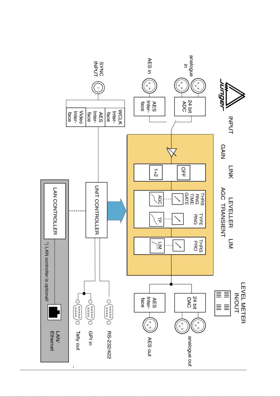
2.2
BLOCK
DIAGRAM
operation manual d06, chapter 2 - Functional Description - page 2 of 8
Page 9
2. FUNCTIONAL DESCRIPION
All signal processing is done in the digital domain by Texas Instruments
floating point signal processors. The use of 32 bit word length for calculation
ensures that there is no deterioration in signal quality, even if an audio signal
with a maximum word length of 24 bit is input into the processing of the unit.
GAIN means linear amplification of input signals. The input gain can be
changed in steps of 0.1 dB , within a range from -20...+20 dB for both
channels.
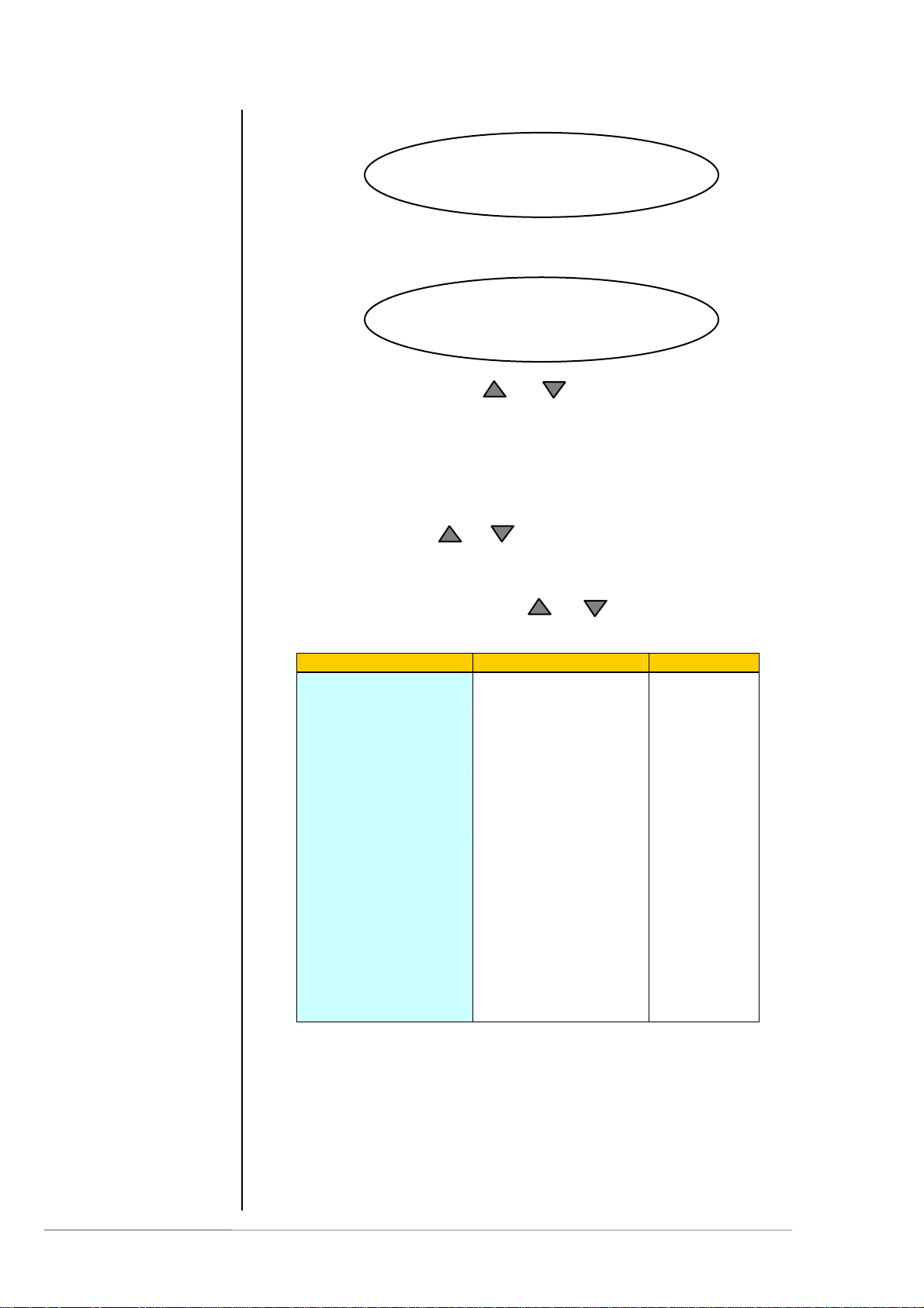
Level Magic ™ is a unique algorithm to make automated audio levelling
possible.
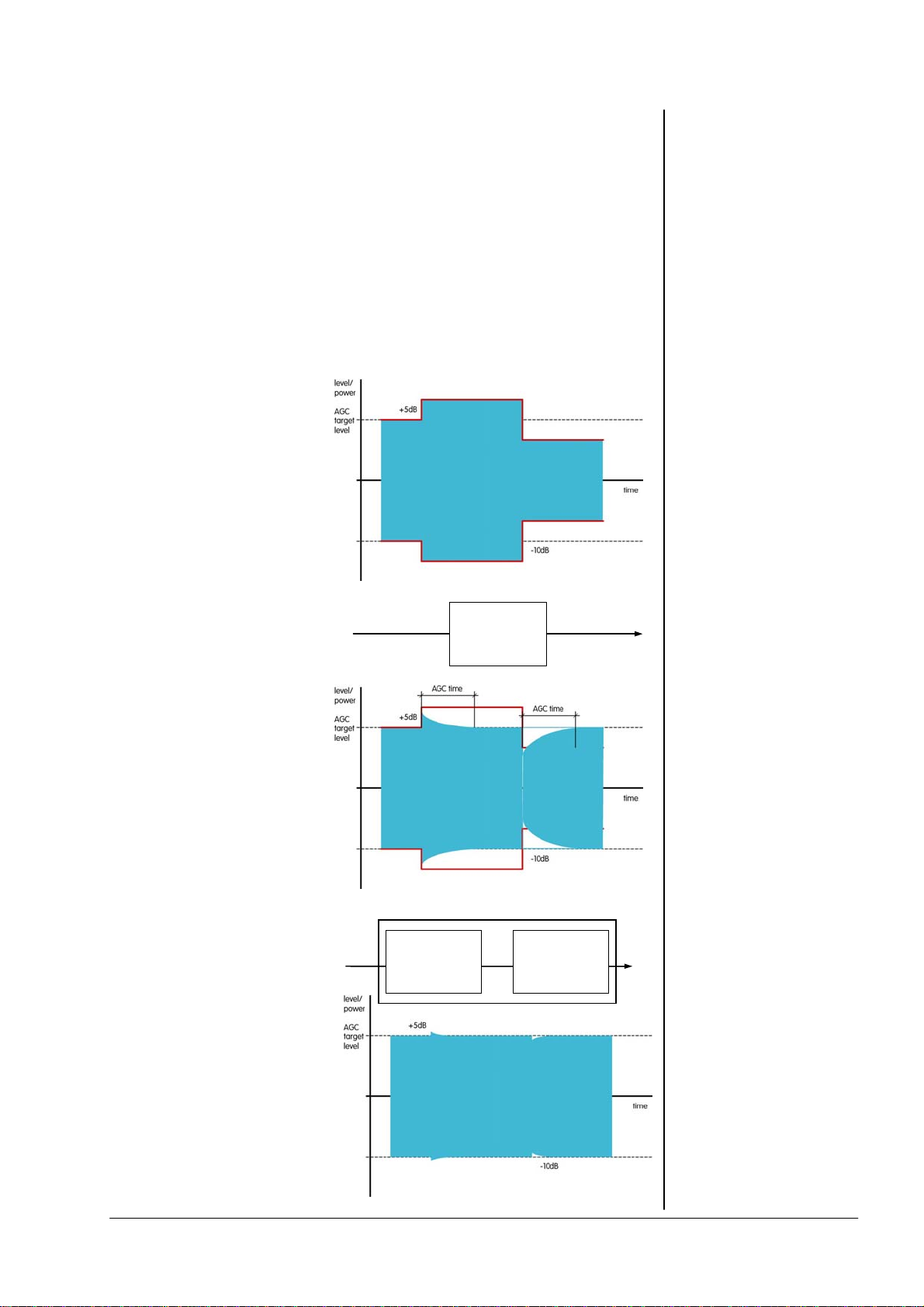
Input level change
Pic. 2 is showing a
theoretical level change of
+5dB and –5dB around
program level.
Working with AGC
In pic.3 a conventional
AGC is used to adjust the
level. As we can see the
AGC needs a certain time
to react, that is necessary
for mostly inaudible gain
correction. But that’s too
long to get a proper
correction of the input level
change.
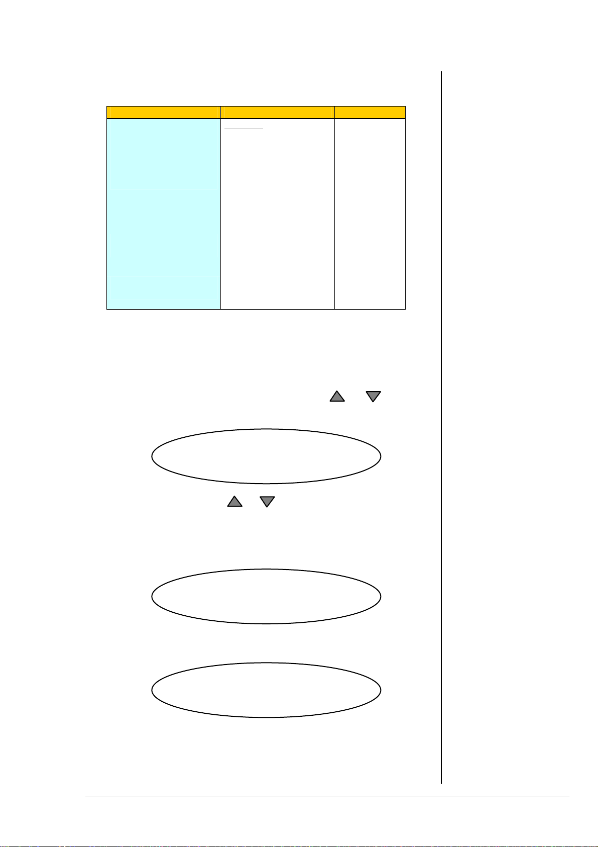
Level Magic ™
Level Magic ™ is a unique
combination of a transient
processor and an adaptive
AGC process. The
transient processor can fill
the lack of level control
against the slow acting
AGC. The total gain of
Level Magic ™ is the
addition of the gain by the
transient processor and the
gain of the AGC.
Transient
Processor
AGC
adaptive
AGC
2.3
AUDIO SIGNAL
PROCESSING
2.3.1
GAIN
2.3.2
AUDIO LEVELLER
LEVEL MAGIC™
operation manual d06, chapter 2 - Functional Description - page 3 of 8
Page 10
Adjustment
procedure
Process
description
2. FUNCTIONAL DESCRIPTION
The Level Magic ™ process needs to be setup in three steps
- select one of the default presets for your apllication
(see preset description in chapter 5)
- adjust the operation level and peak level referring to standards that
are used for your application
- if the default preset is not giving satisfying results change the
parameters indivdually
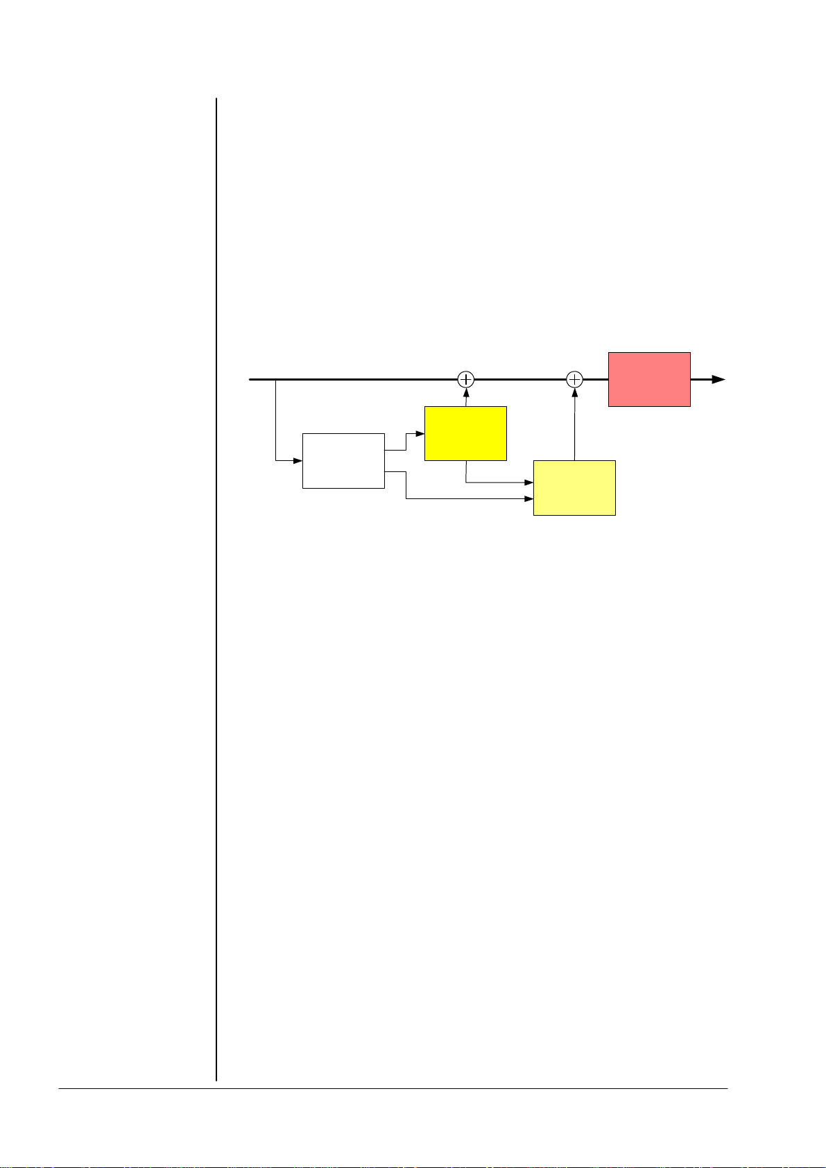
Level Magic ™ is using a unique combination of QP and RMS level detectors
to analyze the incoming audio signal. By comparing QP and RMS
measurement results we can find out how much transients are coming in.
Dependent on that the necessary resulting gain is controlled in relation
between transient processor and AGC.
Limiter
Transient
Processor
Level
Detection
AGC
Parameter
description
Transient processor is doing fast gain change and the AGC is doing slow gain
change (depending on settings). The way how Level Magic is acting on the
audio is mostly determined by balancing between slow and fast gain changing
process. The AGC should be set in a way that the gain change is mostly
inaudible (1dB per 5 seconds or slower). The Transient Processor should be
set that incoming level jumps are reduced but originally dynamic range is not
changed too much. As more possible gain by the Transient processor
(RANGE), as more reduction of the dynamic range will be.
SOFT level control: AGC range …15dB, time >=2min
Transient range …4dB, soft process
MID level control: AGC range …12dB, time >=1min
Transient range …6-8dB, mid process
HARD level control: AGC range …10dB, time >=40sec
Transient range …10dB, hard process
Parameter description:
AGC
OP-level operation level, target level for the AGC and for
the Transient Processor
Range max. gain by the AGC
Time time to reach the max. gain change
Gate threshold level where the AGC stops gain
change and moves gain slowly to the long
term average gain
Transient Processor
Process a combination of level ratio and release
characteristic for the fast gain change (soft, mid,
hard)
Range max. level change by the Transient Processor
operation manual d06, chapter 2 - Functional Description - page 4 of 8
Page 11
2. FUNCTIONAL DESCRIPION
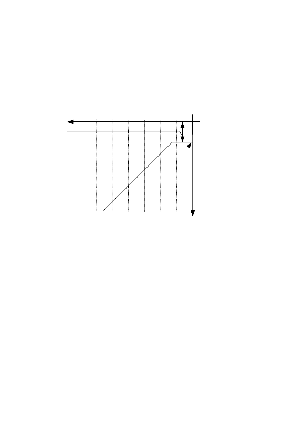
The static characteristics of the d06 limiter usually refers to a digital output
level of 0 dBFS (dB Full Scale). This is useful for most applications of the
dynamics processor as the on-following digital recording system is supposed
to be balanced down to the final bit.
For applications using headroom the output level can be adjusted within 0 ... -
20 dBFS in steps of 0.1 dB. The limiter threshold determines the maximum
output level.
The static characteristic for the limiter at a limiter threshold of -12dBFS is
illustrated in fig. 6.
limiter
threshold
0...-20dBFS
input
-40
-60
-50
max. output
level
-30
-20
-10
[dBFS]
-10
-20
-30
2.3.3
LIMITER
fig. 6:
basic function:
limiter
-40
-50
output
For the dynamics functions a signal delay of approx. 2 ms is built in. This
delay makes it possible to arrange the algorithm of the limiter in such a way
that the control mechanism is activated before maximum level is reached (look
ahead limiter). Within the rise time of the signal the peak level is recognised
and the maximum is calculated in such a way that limiter threshold level is
reached precisely without causing clipping.
A change in the dynamic range of an audio signal is a non-linear process. The
gain of a dynamic range processor is not constant as it is with the gain of a
linear amplifier. The gain varies in time depending on the input signal and
depending on the specific control algorithm of the dynamics processor. These
variations in the gain, which represent the real control process, should take
place without any bothersome side effects.
The dynamic range processor principle developed by Jünger Audio makes it
possible to realize dynamics processors (compressor, limiter, expander) with
very high audio quality, without signal discoloration, pumping or breathing,
without distortion and modulation products - in short, with almost inaudible
processing - and they are very easy to use.
2.4
THE JUNGER
AUDIO DYNAMICS
PROCESSOR
PRINCIPLE
operation manual d06, chapter 2 - Functional Description - page 5 of 8
Page 12
2. FUNCTIONAL DESCRIPTION
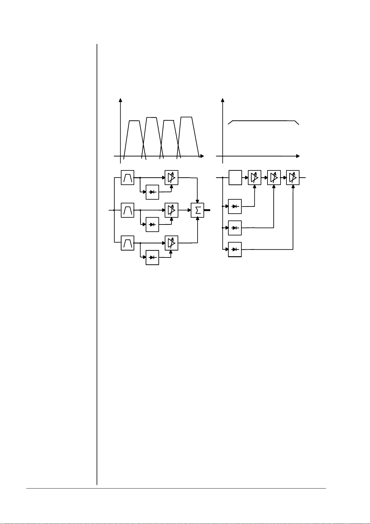
The Junger Audio dynamics processors work according to a Multi-loop
principle, operating with an interaction between several frequency linear
control circuits. This is quite different to the popular multiband structure which
changes the sound.
A A
Multi - Band
f
delay
1
Multi - Loop
1
2
2
n
m
f
2.4.1
PROGRAM
The resulting attack and release times of the Multi-loop system are variable
and adapted to the evolution of the input signal. This allows relatively long
attack times during steady-state signal conditions but also very short attack
times when there are impulsive input transients.
The Multi-loop structure also permits a short time delay between the control
circuit and the gain changing element. The gain control circuit has time to
preview the signal and become active before it reaches the output. This is
particularly important for the limiter, which provides a precisely leveled output
signal absolutely free of overshoots (clipping).
For some of the control parameter it is possible to define a limited range of
time constant values which are allowed for the adaptive dynamic range
algorithms. Inside this range the time constants can be varied by the adaptive
processing. Setting the range of time constant values may be sometimes
useful, to get the best signal processing performance regarding specific
programme material.
Parameter related to the transient response of the control circuit are important
for distortionfree processing. These time constants are allways adaptive
controlled without remarkable limitation of parameter range. This is caused by
the presence of transient pulses in allmost each kind of programme material.
The algorithm has to guarantee best reaction for fast increasing level of
transient signals anytime even if classical music with slow dying out
characteristic is processed. In all cases the attack time of the limiter for very
short transients is zero.
operation manual d06, chapter 2 - Functional Description - page 6 of 8
Page 13

2. FUNCTIONAL DESCRIPION
Especially the release time of the control circuit has more influence to the
increase of loudness as any other parameter. The ranging of time constants in
processing time groups reflects this fact. The range for processing time shows
influence on release time parameter mostly.
The selection of the parameter limiter PROCESS changes the range of time
constant values as follows:
PRO processing time
-------------------------------------------------------- 0 2 ms to 0.2 sec
1 5 ms to 0.5 sec
2 10 ms to 0.8 sec
3 15 ms to 1.2 sec
4 30 ms to 2.5 sec
5 50 ms to 3.5 sec
6 70 ms to 5.0 sec
7 100 ms to 6.0 sec
8 150 ms to 8.0 sec
9 250 ms to 10.0 sec
The audio signal delay through the dynamics processor is approx. 2ms due
to delaying of the audio signal using internal memory. A small delay is
deliberately introduced to the audio signal in order to allow limiter and
compressor algorithms which can 'preview' the audio signal before
changing it. That is the signal curve can be changed before maximum level is
reached. This delay must be considered before attempting to mix signals
processed by the dynamics processor with other undelayed signals.
When mixing together a delayed signal and a direct signal there may be
cancellation of the signal waveform at some frequencies and re-inforcement
of the waveform at other frequencies (comb filter effect). Corresponding
2ms delay of direct signals should therefore be carried out before mixing
them with delayed processed signals.
2.4.2
INFLUENCE OF
SIGNAL DELAY
TIME
operation manual d06, chapter 2 - Functional Description - page 7 of 8
Page 14

2. FUNCTIONAL DESCRIPTION
operation manual d06, chapter 2 - Functional Description - page 8 of 8
Page 15

3. INSTALLATION
INSTALLATION
The digital audio level processor d06 was packed carefully in the factory and
the packaging is designed to protect the equipment from rough handling.
Please examine carefully the packaging and its contents for any signs of
physical damage, which may have occured in transit.
The digital audio level processor d06 is a device under the safety category
Schutzklasse 1 in keeping with the VDE 0804 standards and may only used
with power supply installations built according to regulations.
Check the voltage details printed at the rear panel are the same as your local
mains electricity supply.
The digital audio level processor d06 is equipped with standard connectors
(see also chapter 3).
Before connecting the digital audio level processor d06 switch the power off at
all connected units.
The digital audio level processor d06 is made as standard 19“ unit (EIA
format). It occupies 1 RU (44 mm height) space in a rack. Please allow at
least additional 3inch of space for the connectors on the rear panel.
When installing the unit in a 19“ rack the rear side of the unit needs some
support, especially for mounting in flight cases.
The digital audio level processor d06 should not be installed near units which
produce strong magnetic fields or extreme heat. Do not install the audio
processor directly above or below power amplifiers.
If, during operation, the sound is interrupted or displays no longer illuminate,
or if abnormal odor or smoke is detected immediately disconnect the power
cord plug and contact your dealer or Junger Audio.
3
3.1
UNPACK THE
UNIT
3.2
POWER SUPPLY
3.3
CONNECTIONS
3.4
RACK MOUNTING
3.5
OPERATION
SAFETY
operation manual d06, chapter 3 - Installation - page 1 of 10
Page 16
3.6
SYNCHRONIZING
THE DIGITAL
OUTPUT
3.7
REAR PANEL
CONNECTORS
LAN-controller
web interface
3. INSTALLATION
The digital audio level processor d06 has a digital signal output. For the
problem-free combination of following digital devices, the digital signal
processing can be locked to an external clock reference. The selection of the
corresponding sync source is made in the SYNC MODE menu during setup. If
the chosen sync input is connected with the sync signal, this signal is used for
synchronization automatically. All sync sources can be used for locking A/Dconverters at the analogue inputs as well. The digital output signal can be
clocked with the following clock frequencies:
INTERNAL locks both the A/D-converters and the digital output with
the internal reference 44,1 or 48 kHz. Digital inputs are
connected via sample rate converter
AES INPUT locks with the clock frequency of the input signal at
EXT AES locks with the AES signal at the sync input
EXT WCLK locks with the word clock signal at the sync input
EXT VIDEO locks with black burst at sync input (internal 48 kHz) Digital
Important Note! Video Sync is an option for the d06. For the very rare case
that you can not synchronize the d06 to AES, you may buy such option from
Junger Audio. Pls contact your local dealer for details.
GPI REMOTE
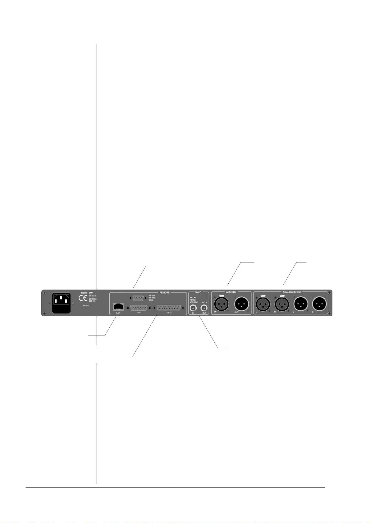
IN/OUT
POWER INPUT
IEC mains input connector 85-264V, 50/60 Hz with integrated fuse
REMOTE
serial remote interface RS-422 (232)
connector: 9pin SUB-D, female
GPI
parallel remote interface
TALLY-out open relay contact
connector: 25pin SUB-D, female
GPI-in optical coupler +3,5…+30V
connector: 15pin SUB-D, female
digital input CH 1/2 (AES/EBU, 44,1...48 kHz)
(AES, 44,1...48 kHz) Digital inputs are connected via sample
rate converter
(WCLK, 44,1...48 kHz) Digital inputs are connected via sample
rate converter
inputs are connected via sample rate converter
SERIAL
REMOTE
DIGITAL
I/O
SYNC IN
WCLK OUT
ANALOGUE
I/O
operation manual d06, chapter 3 - Installation - page 2 of 10
Page 17

3. INSTALLATION
SYNC
SYNC IN input for ext. sync signals :
AES 3 format, 75 Ohm, unbalanced
video sync (black burst), 75Ohm, unbalanced
word clock (TTL level), 75Ohm, unbalanced
Connector : BNC socket
WCLK OUT output for word clock (system clock of d06)
(TTL level), 75Ohm
Connector : BNC socket
DIGITAL IN
AES/EBU standard format
Connector : XLR female
DIGITAL OUT
AES/EBU standard format
Connector : XLR male
ANALOG IN/OUT
Analog input 24bit A/D-converter
floating, balanced
Connector : XLR female
Analog output : 24 bit D/A-converter
Floating, balanced
Connector : XLR male
The analogue audio inputs are RFI filtered. Analog I/Os are balanced and
floating like transformer coupled devices. All the audio connectors are via rear
panel mounted connectors. Standard XLR connectors are used. These are
always wired to the AES standard:
pin 1 X Shield
pin 2 L Live audio 0°
pin 3 R Return audio 180°.
Balanced connections are preferred whenever the other equipment provides
balanced inputs/outputs. All line level connections should be wired with twin
shielded cable for low noise and reliability. The shields of the cable should be
connected at one end only. Input cable shielding therefore needs to be
derived from the signal source end as pin 1 is ground lifted for low frequencies
at the inputs.
If the equipment that drives the digital audio level processor d06 has
unbalanced outputs you must add a wire jumper to connect Pin 1 of the XLR
to Pin 3.
If the equipment connected to the d06 has unbalanced inputs only, we
recommend to use a balanced (i.e. 2 core shielded) cable where Pin 1 and
Pin 3 are connected in the XLR plug end away from the digital audio level
processor d06.
3.7.1
AUDIO
CONNECTIONS
operation manual d06, chapter 3 - Installation - page 3 of 10
Page 18
3.7.2
GPI
3. INSTALLATION
The digital audio level processor d06 can be remote-controlled by means of
parallel GPI inputs.
Use to
* switch between STEREO / 2CH link mode
* selection of INPUT 2 / 1
* switching the device to BYPASS
Connector :
Pin assignment of the connector :
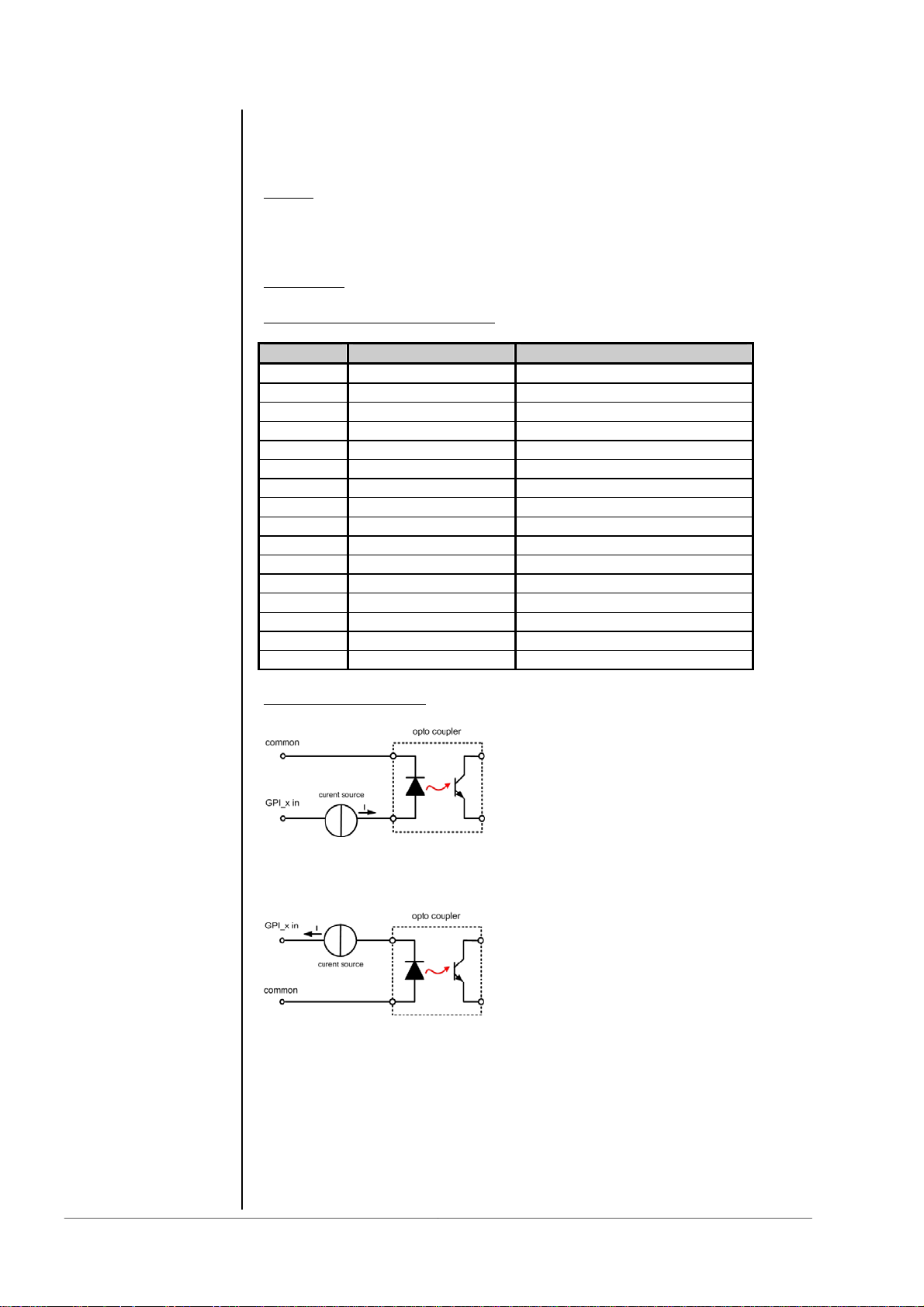
Electrical specification :
GPI input potential free by opto-coupler in line with
a current source
For serial numbers S/N 59 and higher (HW Revision 2a and higher) the
polarity of the GPI inputs has been changed. to make use of the internal
ground based auxiliary 5 V for "low active" switching.
Signal duration must be at least 50msec.
Note : An internal auxiliary voltage feed of +5V is available on pin 9
via a 110 Ω resistor. Ground is available from the shield of the connector
only! When using the auxiliary voltage feed, there is no electrical isolation
given anymore and the risk to inject unwanted noise is high!
Important Note : You must take care about the polarity of the external voltage
applied to the GPIs. Wrong polarity may destroy electronic components
and may cause fire inside the d06!
: * recall of PRESETs 1-4
D-SUB 15pin, female
Pin Signal name Functions
1 GPI1 in Defined by d06 config
2 GPI2 in Defined by d06 config
3 GPI3 in Defined by d06 config
4 GPI4 in Defined by d06 config
5 GPI5 in Defined by d06 config
6 GPI6 in Defined by d06 config
7 GPI7 in Defined by d06 config
8 GPI8 in Defined by d06 config
9 + 5V 110 Ω
10 GPI1/GPI2 common
11 GPI3 common
12 GPI4 common
13 GPI5 common
14 GPI6 common
15 GPI7/GPI8 common
Shield -5V GND of d06 Chassis
ON: +3.5…+30V between GPIx input
and GPx common
OFF: less then 1.5V between GPIx input
and GPIx common
ON: -3.5…-30V between GPIx input
and GPx common
OFF : less then 1.5V betwee GPIx input
and GPIx common
operation manual d06, chapter 3 - Installation - page 4 of 10
Page 19

3. INSTALLATION
The digital audio level processor d06 can aknowledge specific device statuses
via parallel GPO (Tally) lines.
Use to
Connector
female panel jack
Pin assignment of the connector :
Electrical specifications :
Tally output relay : common / normally closed / normally opened
24V - 1A
125V - 0,5A
P
: monitor the d06 status
: D-SUB 25pin
Pin Signal name Functions
1 Tally 1 normally closed
2 Tally 1 normally opened Defined by d06 config
3 TALLY 2 common
4 Tally 3 normally closed
5 Tally 3 normally opened Defined by d06 config
6 TALLY 4 common
7 Tally 5 normally closed
8 Tally 5 normally opened Defined by d06 config
9 Tally 6 common
10 Tally 7 normally closed
11 Tally 7 normally opened Defined by d06 config
12 TALLY 8 common
13 + 5V 110 Ohm
14 TALLY 1 common
15 Tally 2 normally closed
16 Tally 2 normally opened Defined by d06 config
17 TALLY 3 common
18 Tally 4 normally closed
19 Tally 4 normally opened Defined by d06 config
20 TALLY 5 common
21 Tally 6 normally closed
22 Tally 6 normally opened Defined by d06 config
23 TALLY 7 common
24 Tally 8 normally closed
25 Tally 8 normally opened Defined by d06 config
Screen -5V GND of do6 chassis
= 62,5VA
max
3.7.3
GPO (TALLY)
operation manual d06, chapter 3 - Installation - page 5 of 10
Page 20

3.7.4 Serial
RS422
or
RS 232
or
CAN
3. INSTALLATION
The digital audio level processor d06 can be remote-controlled by means of
serial remote RS-232/422.
Use
: * network configuration
* administrative setup (consol interface)
Protocol :
Connector
female panel jack
Pin assignment of the connector in serial interface mode :
Pin assignment in CAN-bus mode :
This connector has multiple functions which may be internally changed by
connectors and jumpers (see 3.8). The factory default format setting is RS232
and it is connected with the serial interface of the LAN Controller.
By using a terminal program (115kB/sec. 8,N,1 no flow control) you may
communicate with the consol of the LAN Controller, e.g. to change the IP
configuration of the device.
available on request
: D-SUB 9pin
Pin Signal name Functions
1 Rx + RS422
2 TxD RS232
3 RxD RS232
4 NC not used
5 GND Ground
6 Rx - RS422
7 NC not used
8 Tx - RS422
9 Tx + RS422
Pin Signal name Functions
1 NC Not used
2 CAN-l CAN-bus low signal
3 NC Not used
4 NC Not used
5 GND Ground
6 GND Ground
7 CAN-H CAN-bus high signal
8 NC Not used
9 NC Not used
operation manual d06, chapter 3 - Installation - page 6 of 10
Page 21

3. INSTALLATION
Connector : RJ 45 with status LEDs
8 pin panel jack
Pin assignment of the connector :
Pin Signal name Functions
1 TX + Ethernet send
2 TX - Ethernet send
3 RX + Ethernet receive
4
5
6 RX - Ethernet receive
7
8
9
Electrical specifications : 100Mbit/s auto negotiation port
Application remarks :
This port allows remote control of the d06 by TCP/IP over Ethernet (web
interface). Setting up the network interface is described in chapter 4.
The LAN Controller of the d06 has a web server which offers a graphical user
interface (GUI). For proper operation you need IE7 or FireFox 2.0.
You simply must use the IP address of the do6 as an URL. (see chapter 5.1
for details).
d06 control block diagram :
3.7.5
LAN
(Ethernet)
operation manual d06, chapter 3 - Installation - page 7 of 10
Page 22

3.8
A
Switches and
jumpers for
configuration
3.8.1
Selection of the
serial remote
interface
3. INSTALLATION
Some basic settings can be done by switches and jumpers on the PCB.
These settings are general changes for operation and should be performed by
qualified engineering staff only.
To set any internal jumper or switches it is necessary to open the unit.
Important Note! DO NOT CHAGE ANY SETTINGS WHILE POWER IS
CONNECTED TO THE UNIT!
Loosen the screws on the top cover and remove. Then you can see all jumper
and switches as shown in the schematic below. After setting of jumper or
switches reassemble the unit in opposite order.
D06/07
J2
232/422
J3
/B
3.8.2
Calibration of the
analog inputs and
outputs
DSP card
J2 : RS-232 / RS-422 (format selection)
J3 : A / B serial Interface of the DSP controller (A)
The factory default calibration of the d06 is done in reference to the German
radio broadcast standard, i.e. +15dBu = 0dBFS. If you want to use a different
reference standard (e.g. +24dBu = 0dBFS) you can change the setting via dip
switches on the main board of the d06 :
The DIP switches are located close to the analog input and output hardware
on the PCB.
Main board
or the LAN controller (B)
operation manual d06, chapter 3 - Installation - page 8 of 10
Page 23

3. INSTALLATION
For the factory setting of +15dBu=0bBFS the DIP switch
“+15dBu” is turned ON.
To change the setting for another standard the respective DIP switch must be
set to ON while all others must be OFF.
Important Note! Make sure that there is only one DIP switch turned ON!
CUSTOM Refernce Level (using Switch 6 ADJ)
If none of these stansard reference settings correspond to your needs, you
may set the reference to a CUSTOM level by adjusting the input sensitivity via
the two potentiometers (L and R) next to the analog input and output
connectors at the rear of the box.
Important Note! This should only be done with measuring instruments!
Set up the reference level manually :
1. Set all dip switches to OFF except #6 (ADJ) = ON.
2. Adjust the potentiometers to the desried CUSTOM reference level.
You must feed the analog input with a known refernce level and
measure the digital output.
Important Note! Make sure that the DSP processing is bypassed,
because it may add gain, that gives wrong level reading at the output!
3. When the adjustments are complete, ‘freeze’ the custom settings by
setting DIP switch #6 to OFF. If not, your reference level set up may
be changed by accident.
operation manual d06, chapter 3 - Installation - page 9 of 10
Page 24

3. INSTALLATION
operation manual d06, chapter 3 - Installation - page 10 of 10
Page 25

4. NETWORK INTERGRATION
NETWORK INTEGRATION
To control the Junger audio devices via web browser you must set up an
TCP/IP over Ethernet connection. If you are not familiar with the network
setup, please consult a network administrator for assistance and read ALL
the manual carefully!
There are two ways to communicate with the device via Ethernet:
1. You can connect the device to the LAN your PC is integrated
(if there is one existing already)
2. You can connect the device directly to your PC using an
Ethernet crossover cable.
In both cases network settings of the device or your PC or even both have to be
changed and matched.
The default network configuration of the Jünger devices is:
IP Address : on a label at the LAN connector socket at the rear of the device
Netmask : 255.255.0.0.
Gateway : 10.110.0.1.
1. Integration into an existi ng LAN
When you want to integrate the device into an existing LAN you have to
change its IP-address, the (sub) network mask and the gateway. You will get
valid settings from your network administrator.
You can do that two ways :
A Connecting the device over a serial cable to your PC and change the
network configuration with a terminal program (e.g. HyperTerminal
included in Windows installation)
B Disconnect your PC from your LAN (physically), match your PC’s
IP setup to the setup of the device for getting access to the device via
Ethernet crossover cable, change the device’s network configuration via
Ethernet crossover cable. Then change again your PC’s configuration
and connect both your PC and the device to the LAN.
4
operation manual d06, chapter 4 - Network Integration - page 1 of 6
Page 26
4. NETWORK INTEGRATION
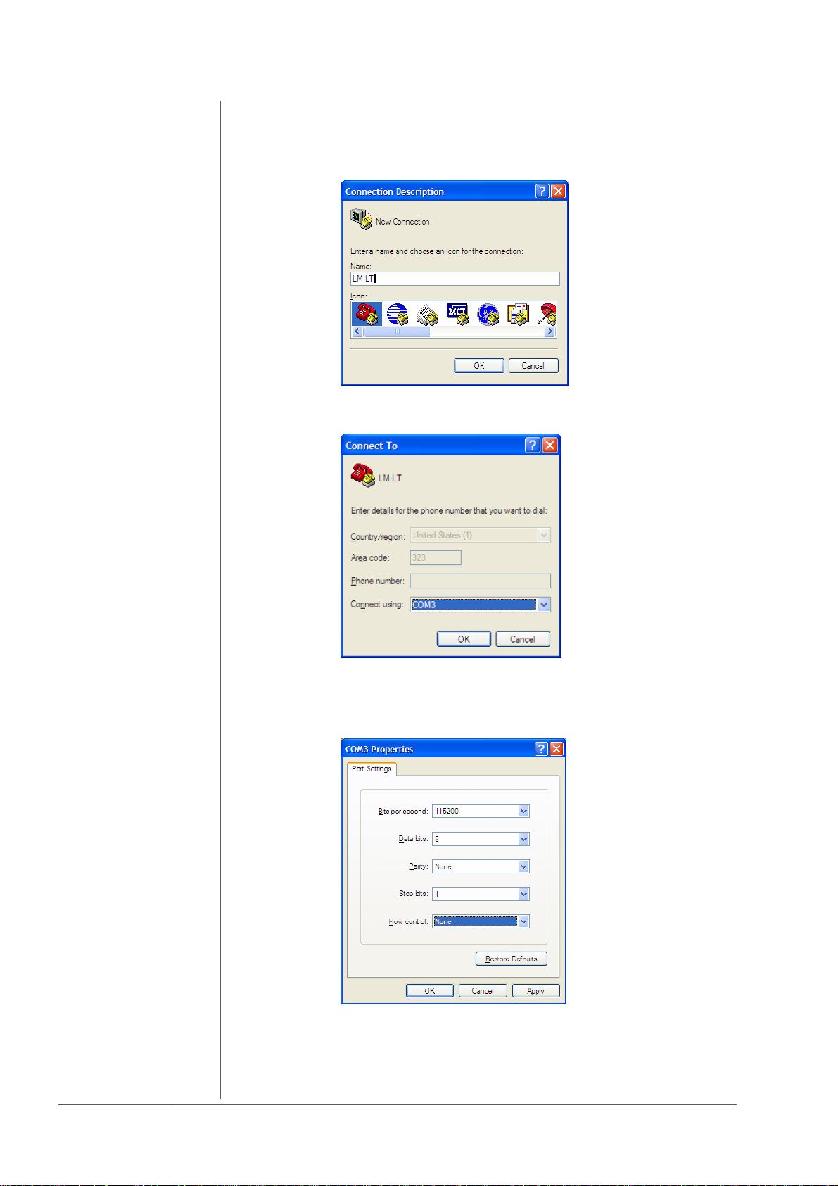
A)
Connect the device via a 9 pin serial cable (connected 1 to 1) to your
PC. Start your terminal program (e.g. Start -> All Programs -> Accessories ->
Communications -> HyperTerminal).
Enter a name of your choice and press OK
Choose the communication port (physical or virtual if you are
using an USB > serial converter) you are working with
and press OK
Set the port settings as they are shown in the window above
and press OK.
operation manual d06, chapter 4 - Network Integration - page 2 of 6
Page 27
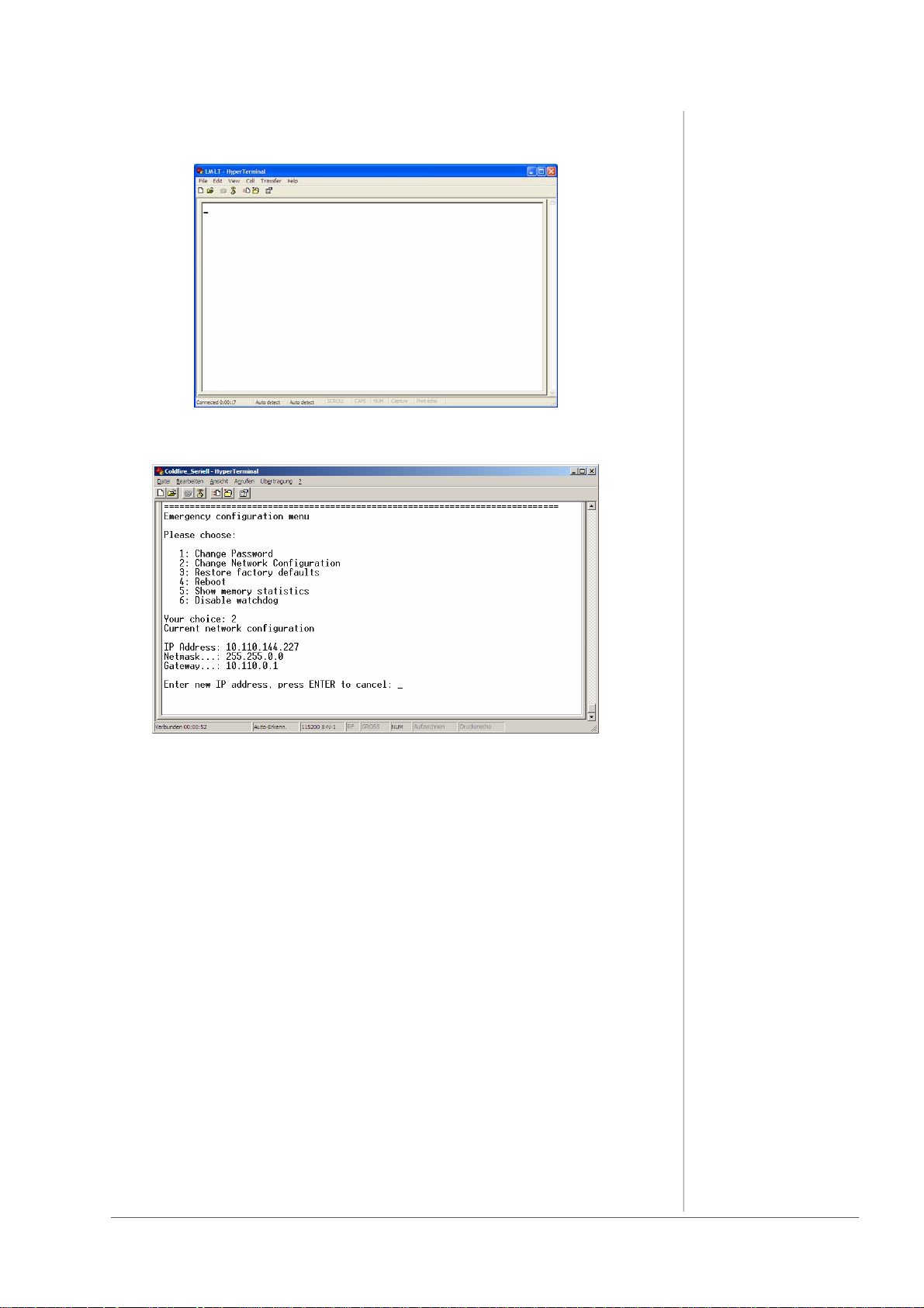
You will get to the Hyper terminal window:
Press ENTER and you will get a similar window :
4. NETWORK INTERGRATION
Now you can change the network configuration so that it fits into your LAN.
You might have changed the IP-address of the device, so please renew the
label at the rear of the device, otherwise it will cause confusion.
When you ever “Restore factory defaults” (i.e. initializing the device) the
default IP-address and network configuration will be active again. In case of
need you can read the default IP-address always on the controller in the
device!
B)
You can also change the IP address of the device over Ethernet connection.
Disconnect your PC from the LAN, connect it to the device directly via
Ethernet crossover cable (not connected 1 to 1, but 1 to 8 etc…).
Change the network configuration of your PC (write down the current settings,
you need them later to reconnect to your LAN!) via the
“Local Area Connection Properties” menu (Windows: Start -> Control Panel ->
Network connections -> Local Area Connection -> Local Area Connection
Status -> Properties -> Internet Protocol (TCP/IP).
operation manual d06, chapter 4 - Network Integration - page 3 of 6
Page 28

4. NETWORK INTEGRATION
Scroll in the list and choose Internet Protocol (TCP/IP).
Make sure that the ‘check box’ for this item is checked, and then click on
Properties.
In this example, the Ethernet TCP/IP is set to ‘Obtain an IP address
automatically.’
If, in your case, it is set to
‘Use the following IP address,’
jot down the current settings on a piece of paper
(IP address, Subnet Mask, and Default gateway, if used).
You will need them later to restore the IP address of the PC to what it is
required to work on your LAN.
operation manual d06, chapter 4 - Network Integration - page 4 of 6
Page 29
4. NETWORK INTERGRATION
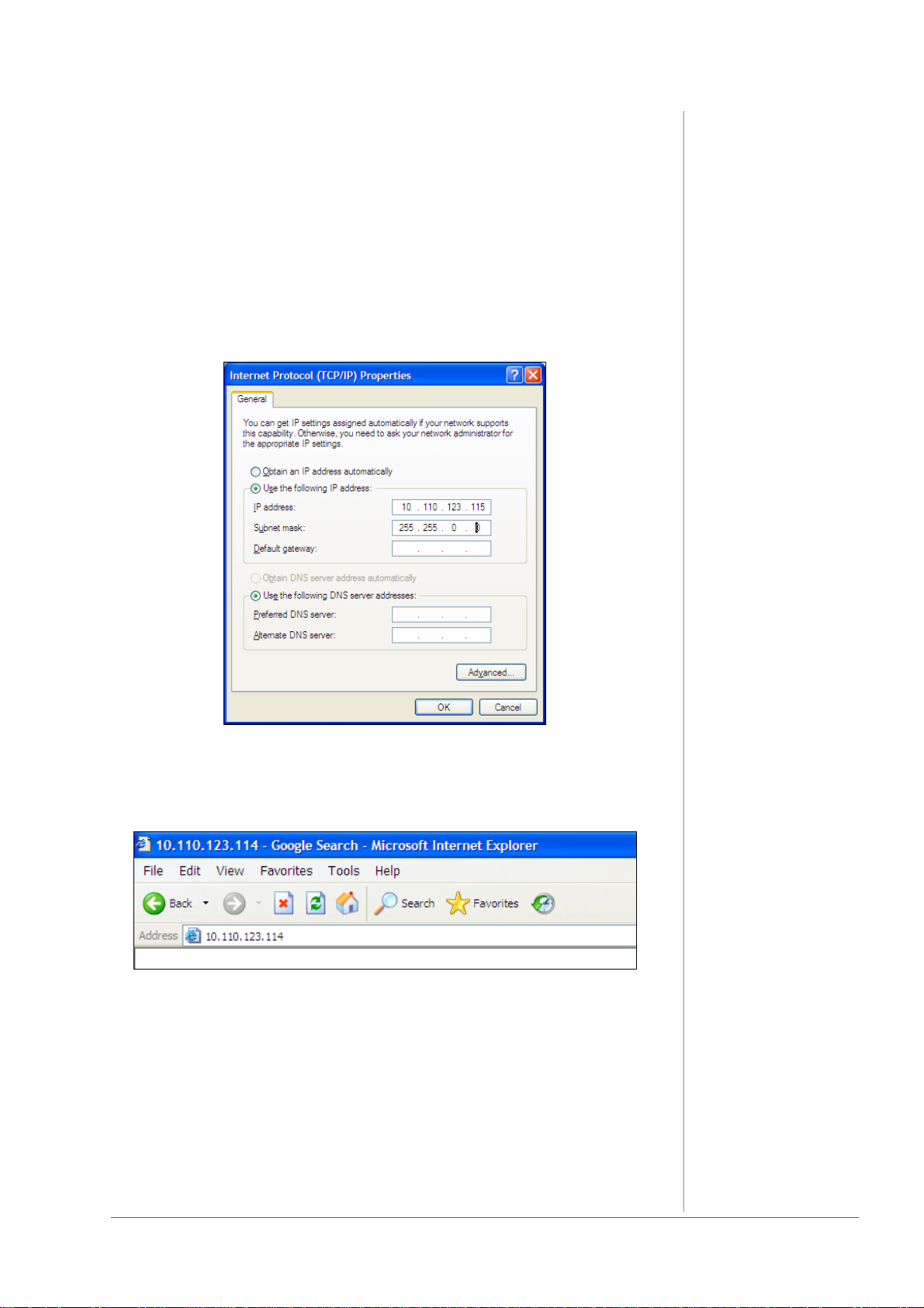
Then change the settings in order to be able to communicate with the device.
You have to choose an IP-address “near” to that of the device.
So if the settings of the device are e.g.
IP Address: 10.110.123.114
Netmask: 255.255.0.0.
Gateway: 10.110.0.1.
You have to take 10.110.123.115 as IP-address (or something near to the
device’s address, only 10.110.123. have to be the same!) and the same
netmask. The gateway is not important when you are using an Ethernet
crossover cable.
When you have changed the settings, press OK. Now you will be able to
communicate from PC to device via web browser (e.g. internet explorer) with an
Ethernet crossover cable. Just type in the device’s IP-address into your
browser:
Then you will come to the modules web page:
operation manual d06, chapter 4 - Network Integration - page 5 of 6
Page 30
4. NETWORK INTEGRATION
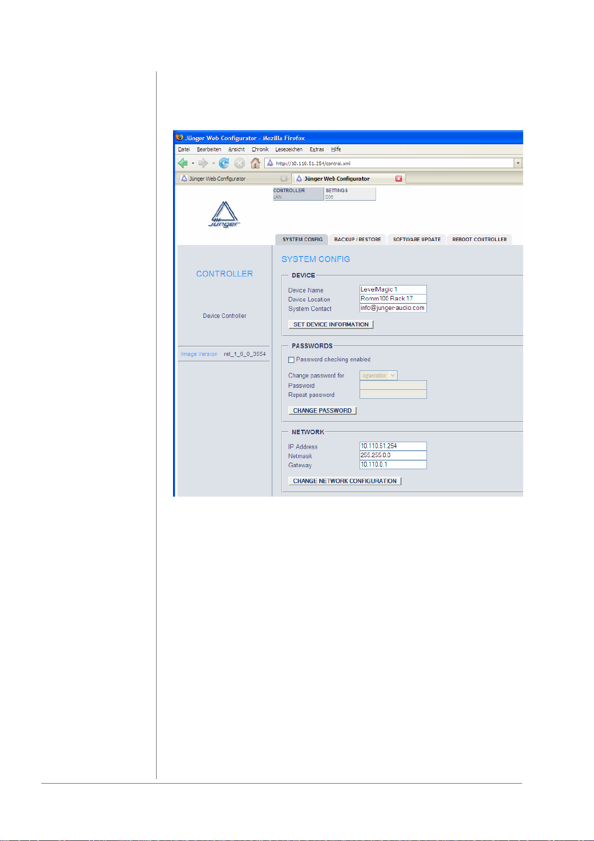
Under CONTROLLER -> SYSTEM CONFIGURATION you will be able to
change the device’s network configuration according to the settings of the LAN
you want to use.
After having changed the settings click CHANGE NETWORK
CONFIGURATION and after that REBOOT THE CONTROLLER and afterwards
reboot the LAN Controller : CONTROLLER -> REBOOT CONTROLLER.
Rebooting the device activates the changes you have made to the network
configuration. If you changed the IP address of the device to a different
network as your PC, you may not be able to reach the web interface after
the reboot.
Now you have to change the settings of your PC network configuration again
and connect both the PC and the device to the LAN you want to use by 1:1
Ethernet cable to a router or hub. Then you will be able to communicate with the
device over web browser via the chosen IP-address.
operation manual d06, chapter 4 - Network Integration - page 6 of 6
Page 31
OPERATION
GUI
5. OPERATION
5.1
GUI operation
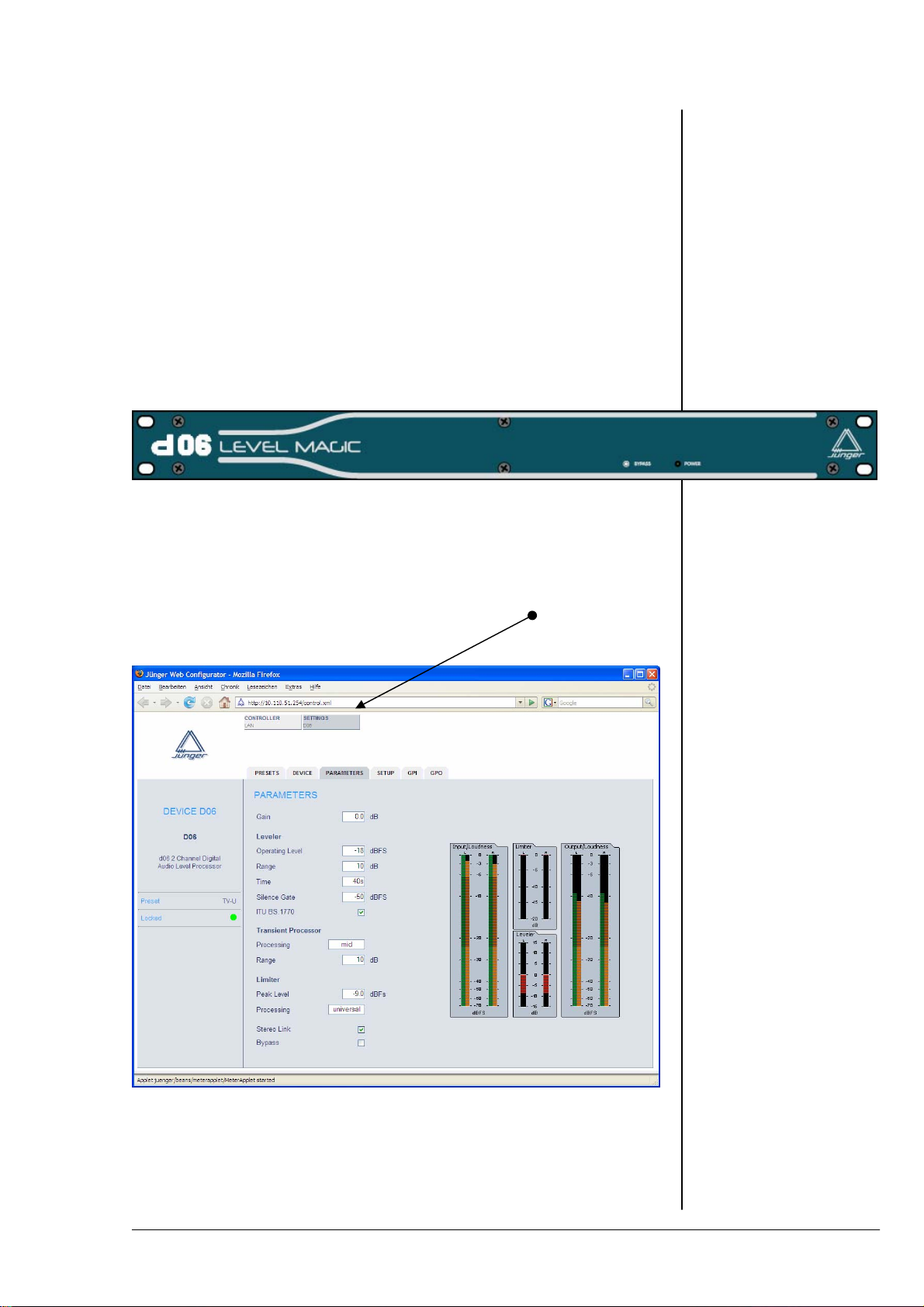
The GUI of the d06 can be reached by connecting the d06 to a PC via
LAN (either by a switch or cross over cable) and using its IP address as
an URL for a web browser. Junger Audio supports both the IE7 and
FireFox 2.0 and higher versions. The application assumes that there is a
JAVA VM (1.6. or higher) installed on that PC in order to display level bar
graphs: You must use the device IP address as an URL to connect
with the d06.
PARAMETERS
This will open the PARAMETERS page of the GUI.
Here you must setup the dynamic operation of the d06.
operation manual d06, chapter 5 - Operation - page 1 of 12
Page 32

5.1.1
Setting the d06
parameters
5. OPERATION
Gain : static gain to align the d06 to the level diagram of the
system / installation
Leveler
Operating Level : the target level of the leveler process
Range : the range for the leveler to move gain up and down in
Time : the time for the leveler process to reach the maximum
Silence Gate : a value for the leveler process to stop gain change. This
ITU BS.1770 : the leveler process may be ITU BS.1770 weighted (see
Transient Processor
Processing : the Transient Processor is a compressor like, fast
Range : the range of the Transient Processor limits the amount
Limiter
Peak Level : the Junger brick wall limiter is well known in the audio
Processing : the algorithms are self adapting to the program. For very
order to match with the Operating Level
Range value (if needed).
The recommendation is, not to be faster than 3dB /
10sec. because this is an area where the human ear may
not recognize a level change
will prevent from unwanted noise if the input level drops
for a longer time below it. If the signal disappears for
longer time, the processing gain will move back to 0dB
ITU documentations for details). This setting applies with
the ITU loudness standard. In the case ITU is enabled,
the Operating Level equals to the Dolby
acting circuit, which deals with fast level changes. Those
level changes are quite different for program genres. For
a maximum fit of the process with different program
types, you may change the behavior. Our
recommendation is to use the “mid” setting for most
programs, while “fast” is recommended for sports style
(Soccer, Tennis, Golf etc.), program
of gain change. A higher value of Range will limit the
dynamic of the input program
industry for its outstanding performance. Due to the fact
that the algorithm will be applied on sample basis and the
look ahead function, there will be newer ever an overload
at the output. On top of that, this value defines the
maximum output level of the d06
critical material it may be advisable to give it a good
starting point, to make the limiter inaudible as possible.
The recommendation is to work with the setting UNI
which works for most of the material
®
Dialnorm Level
operation manuad d06, chapter 5 - Operation - page 2 of 12
Page 33

5. OPERATION
As mentioned before, the d06 has a DSP controller, which also operates the
front panel. You can imagine this controller as the DSP co-processor for all
relevant real time communication.
DEVICE
5.1.2
Setup the device
On this page you may set up a name for the device. This name may be used
in other applications.
Restart DSP : in case of a processing problem you may restart the
DSP and its co-processor by pressing the
<RESTART> soft button
Initialize and Restore Factory Defaults :
this function instructs the DSP controller to set all
PARAMETERS, the PRESETS, the SETUP and the
GPI/Os to values defined by the factory defaults
Controller Version : the firmware version of the DSP controller
DSP Version : the firmware version of the DSP program
Backup Settings and Presets to File :
all relevant variables used by the DSP controller may
be saved to a file for later backup or you may use it to
copy such settings to an other d06
Restore Settings and Presets from File :
you may search for a file to restore the settings of the
DSP controller and start the restore process here
operation manual d06, chapter 5 - Operation - page 3 of 12
Page 34

5.1.3
General settings
5. OPERATION
The d06 has analog as well as digital inputs and it features the external
synchronization of the digital output to an external reference. On this page
you may change such settings.
SETUP
Input : the radio buttons will switch between analog and
digital (AES/EBU) input
Sync : the d06 may be synchronized to :
internal reference 48kHz
internal reference 44.1kHz
AES XLR input
external AES BNC rear connector
External Wordclock BNC rear connector
Video Sync BNC rear connector
Important Note! Video Sync is an option for the d06. For the very rare case
that you can not synchronize the d06 to AES, you may buy such option from
Junger Audio. Pls contact your local dealer for details.
operation manuad d06, chapter 5 - Operation - page 4 of 12
Page 35

5. OPERATION
The d06 has 10 Presets. Those Preset may be recalled by the user at any
time. Preset #5 - #10 are factory Presets while Preset #1 - #4 are user
presets which may be overwritten by the user.
PRESETS
5.1.4
Preset operation
Load Preset : the drop down list offers the selection of one of the 10
Presets of the d06. Pressing the <LOAD NOW> soft
button will load the pre selected Preset
Save as Preset # : the number displayed by the drop down list represents
the memory number of the Preset (#1 - #4), where
you will store
Name : You may give your Presets a digit name here
Backup : You can backup all Presets to a file
Restore Presets from File:
Here you may select a file from the PC file system to
restore all Presets or to copy them to an other d06
operation manual d06, chapter 5 - Operation - page 5 of 12
Page 36

5.1.5
GPI/O set up
5. OPERATION
GPI
5.1.6
LAN Controller
set up
GPI 1 to GPI 8 : you can assign each physical GPI input one function
by moving the slider across the input field.
The options are:
PRESET-1 to PRESTE-4 (loads assigned preset)
STEREO (turns the link mode = On)
DIGITAL (selects the digital input)
BYPASS (activates the bypass relay)
GPO
GPO 1 to GPO 8 : you can assign each physical GPO (Tally) one status
by moving the slider across the input field.
The options are :
PRESET-1 to PRESET-4 (is selected)
STEREO (link mode is selected)
LIMITER (activity of the limiter)
CLIP (input signal is clipping)
DIGITAL (input is active)
BYPASS (relay is active)
The LAN Controller of the d06 provides its own menu. You must press the
<CONTROLLER> soft button:
operation manuad d06, chapter 5 - Operation - page 6 of 12
Page 37

5. OPERATION
5.1.6.1
System
configuration
DEVICE : you may assign the device a name string and a
location string as well as a contact address. This
information may be used by an external monitoring
system like a SNMP manager
PASSWORDS : the do6 may be setup for password operation. If this
function is turned on, one must use the passwords
you may set up here. The password protected mode
knows three different user levels:
The Viewer can only view the
embedded level display
The Operator can change presets in
addition to it
The Administrator can do everything
NETWORK : you may change the IP configuration of the device
METERING : in order to receive data for the level display,
if a local fire wall is active, you must reserve UDP
ports (for which the fire wall will held open).
To set up those UDP ports for local PCs, you must
open the firewall settings (right click on the network
symbol in the task bar of windows and select :
”Change Windows Firewall settings”. This will
open the “General” tab. Click on the “Exceptions”
tab in order to open the Exception page
operation manual d06, chapter 5 - Operation - page 7 of 12
Page 38

5. OPERATION
On the Exceptions page open the “Add Port” menu:
Here you must give this rule a unique name (e.g. “d06 #1.1”) and assign it a
UDP port number from the number of UDP Ports, set up by:
UDP Port Range Start / UDP Port Range End (see METERING).
If you want to connect from different PCs with the same device, it is sufficient
enough to assign one port, because different PCs will open different IP
sockets because they have different IP address (but use the same UDP port
number).
If you want to connect from the same PC with different devices, a unique
UDP port number for every remote device is necessary!
Important Note! To connect multiple browser sessions from the same PC
with the same device is not implemented! In such case the next browser
session will not get UDP data from that device. This will cause a red colored
meter display :
operation manuad d06, chapter 5 - Operation - page 8 of 12
Page 39
5. OPERATION
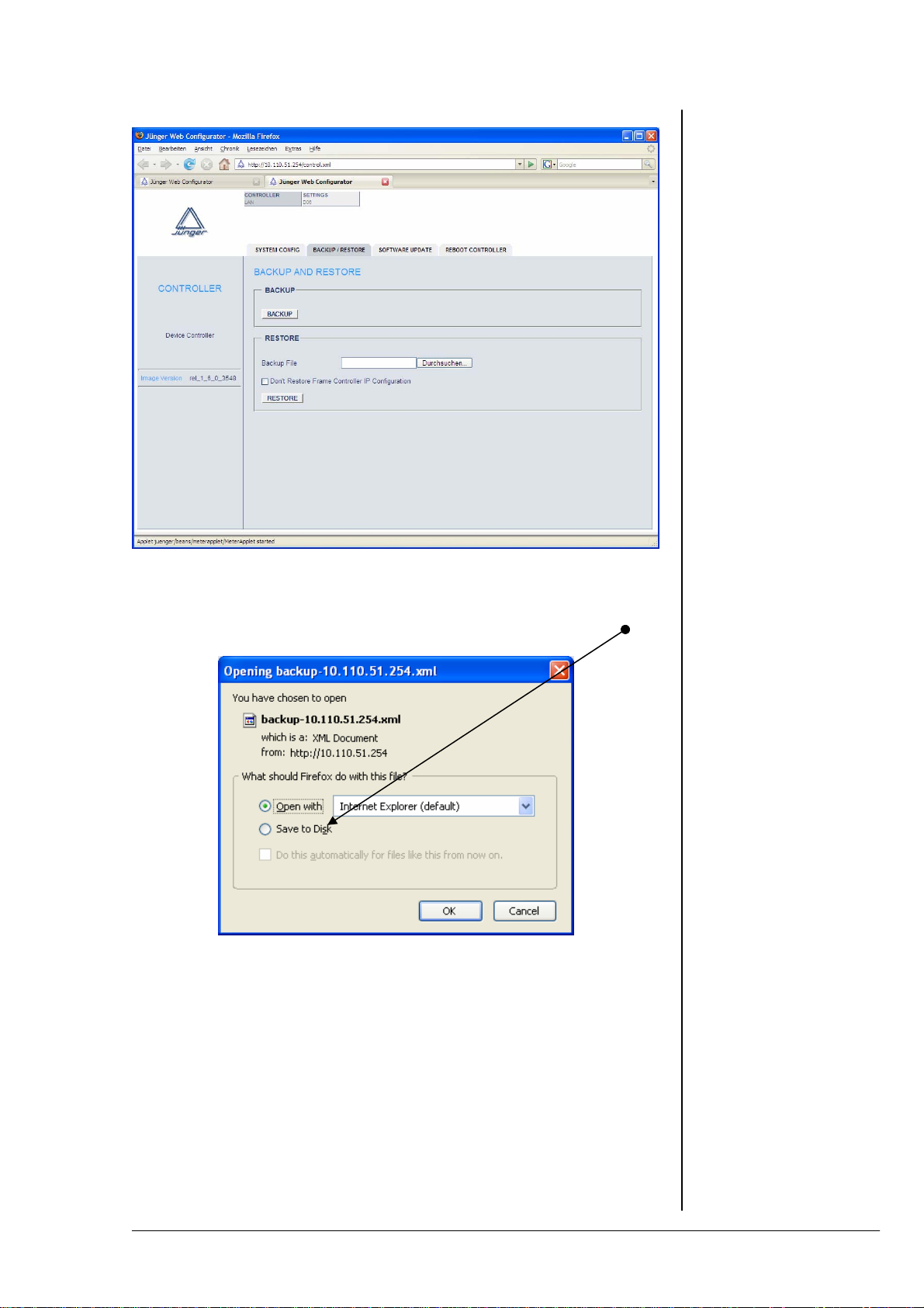
5.1.6.2
Backup & restore
BACKUP : if you press the <BACKUP> soft button, the
LAN Controller will generate an XML file that
represents all settings of the device.
If done, you may download the file to your PC :
RESTORE : here you can select a backup file from the file system.
The process will start when you press the
<RESTORE> soft button.
operation manual d06, chapter 5 - Operation - page 9 of 12
Page 40

5.1.6.3
Software update
5. OPERATION
In chapter 3 we have explained that the d06 has 3 major components :
The DSP, the DSP Controller and the LAN Controller. To update the
LAN Controller, you must select the firmware file (also called the image)
from the local file system of your PC (you may get such file via HTTP
download from Junger Audio). If you press the <START UPDATE NOW>
soft button, the PC will upload the image file to the LAN Controller and will
initiate the “burning” process of its FLASH memory. This will take about
5min. When the process of “burning” the flash memory starts,
you will see a progress bar.
operation manuad d06, chapter 5 - Operation - page 10 of 12
Page 41
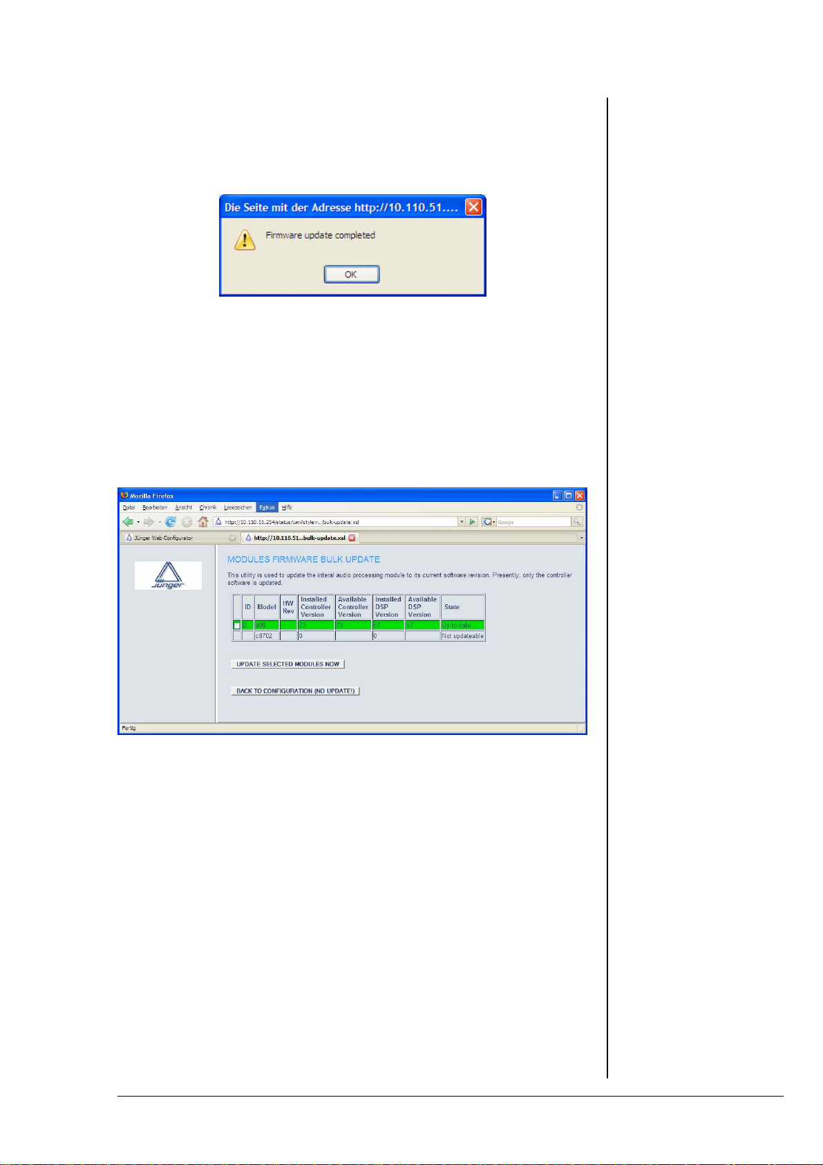
5. OPERATION
From this moment on, there is no communication with the LAN Controller
possible. If the progress bar comes to its end, the browser will restart
communication with the LAN Controller and you will get a message that the
process has finished :
MODULE FIRMWARE BULK UPDATE
The image file also carries the actual firmware files for
the DSP and the DSP Controller. This function offers
you an update of both components. When you press
the soft button, the LAN Controller reads the installed
versions and compares it with the release version it
has “on board”. You will get a display to make a
choice if you want to update :
For the above example there is no update needed.
(C8702 is the internal label for the LAN controller).
MODULE FIRMWARE SINGLE UPDATE
If there is the need to update one of the components
by a firmware that is not “on board” of the LAN
Controller, you may use this function. It offers you
either to update the (DSP) Controller and/or the DSP.
The firmware file must be provided from the file
system of the PC.
REBOOT CONTROLLER
This function allows you to reboot the LAN Controller.
operation manual d06, chapter 5 - Operation - page 11 of 12
5.1.6.4
Reboot the
LAN Controller
Page 42

5. OPERATION
operation manuad d06, chapter 5 - Operation - page 12 of 12
Page 43
OPERATION
front panel
5. OPERATION
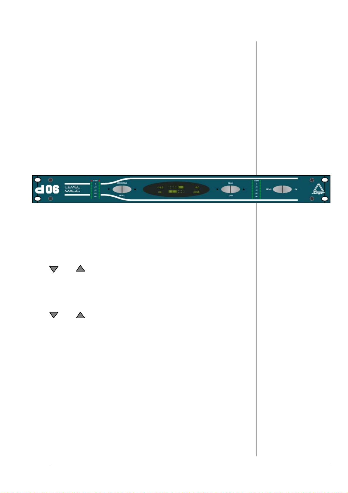
5.2
Front panel
operation
Functions of the buttons :
OPERATING
setup of operating level - OL
setup of parameter values
LEVEL
PEAK
setup of limiter threshold - PEAK
selection of menu items
LEVEL
<MENU> enter a menu / escape a menu
<OK> next menu level
prompt a selection or a value
load / save a preset
operation manual d06, chapter 5 - Operation - page 1 of 8
Page 44

5.2.1
Setting the
reference levels
5. OPERATION
The picture below shows an example main display after power on:
OP ……..…
IIIII
PEAK
5.2.2
Menu selection
5.2.3
Preset menu
-18.0 …
The top display shows the current limiter gain reduction
[0dB at right hand], while the bottom display shows momentary gain
change introduced by the leveler process [0dB at center].
There are two reference levels :
OP = Operating Level (target level of the leveler process)
PEAK = Peak Level (Threshold of the brick wall limiter)
These are top level settings. They can be adjusted without calling the
menu :
Simply press the respective up and down arrow buttons to
change values. The range of the settings are :
OP = -40 … 0dBFS in steps of 1dBFS
PEAK = -20 … 0dBFS in steps of 0,1dBFS
Î If you press the arrow button for more than 2,5 sec. the values will
change automatically
Î Push the OK button to display the actual input level in
numeric values
Press <MENU> to enter menu selection.
Push the PEAK LEVEL or buttons to navigate in either direction:
PRESET CONFIG PARAMETER PRESET
Press <OK> to open one of the selected menus.
……. -9.0
IIIIII
PRESET
Press <OK> to enter the PRESET menu :
LOAD
PRESET 1: PR 1
operation manuad d06, chapter 5 - Operation - page 2 of 8
Page 45

5. OPERATION
Push the PEAK LEVEL or buttons to select LOAD or SAVE :
SAVE
PRESET 1: PR 1
Push the OPERATING LEVEL or buttons to select a preset by
number (example preset # 5) :
LOAD
PRESET 5: TV-U
Important Note: The d06 has 10 presets to load, while presets #1 - #4
may be overwritten by the user, Presets #5 - #10 are factory presets
which can not be overwritten!
Press <OK> to load or save the selected preset and jump back to the
main display or press <MENU> to jump back (escape) to main display
without changes :
OP ……..…
-18.0 …
The table at the end of this chapter shows the values of the factory
PRESETS.
IIIIII
PEAK
IIIII
……. -9.0
operation manual d06, chapter 5 - Operation - page 3 of 8
Page 46
5.2.4
Configuration
menu
5. OPERATION
CONFIG
Press <OK> to enter the CONFIG menu :
INPUT
digital
Push the OPERATING LEVEL or buttons to select between :
digital and analog.
Press <OK> to make selection and jump back to the CONFIG menu or
press <MENU> to jump back (escape) to the CONFIG menu without
changes.
The table below shows the details of the CONFIG menu if you
push the PEAK LEVEL or buttons to select one of the
CONFIG parameters.
For each CONFIG parameter there are several values.
If you push the OPERATING LEVEL or buttons you will select
one of these values :
Parameter Value Class
INPUT
SYNC
MODE
LOCK
PASSWORD
There are 4 digits
GPI
(There are 6
physical GPIs)
analogue
digital
intern 48 kHz
intern 44,1 KHz
Input
extern AES
2-channel
stereo
unlocked
locked
0 1 2 3 4 5 6 7 8 9
OFF
PRESET1
PRESET2
PRESET3
PRESET4
STEREO
INPUT2
BYPASS
SETUP
SETUP
PRESET
SETUP
SETUP
SETUP
operation manuad d06, chapter 5 - Operation - page 4 of 8
Page 47
5. OPERATION
Table continues from previous page
Parameter Value Class
TALLY
(GPO)
(There are 8
physical GPOs)
SOFTWARE
VERSION
CONTRAST
BRIGHTNESS 1
8 Tallies :
OFF
PRESET1
PRESET2
PRESET3
PRESET4
STEREO
LIMIT
CLIP
INPUT2
BYPASS
C: controller firmware #
D: DSP firmware #
0 … 7 SETUP
0 … 7 SETUP
SETUP
Display only
The Class column shows where such parameter belongs to,
if it will be stored in a preset or not.
The PASSWORD, GPI and TALLY menus have a 3
rd
level so you must
press <OK> again if you want to make changes there.
E.g. to change the password, push the PAEK LEVEL or
buttons to move the flashing arrowheads between the four digits :
PASSWORD
> 1 < 2 3 4
Push the OPERATING LEVEL or buttons to change the
respective number.
If the d06 front panel is locked to prevent from unauthorized operation,
one will be notified in the main display if you push a cursor button :
locked
You may press the <MENU> button now, to open the password menu :
ENTER PASSWORD
> 1 < 2 3 4
See above how to enter the correct password. If done press <OK> to
open the front panel operation again. It will stay open until you reach the
upper menu level (main display). This will lock the front panel again.
operation manual d06, chapter 5 - Operation - page 5 of 8
Page 48

5.2.4
Parameter menu
5. OPERATION
PARAMETER
Press <OK> to enter the PARAMETER menu :
GAIN
0.0 dB
For each PARAMETER there are several values. You must
push the OPERATING LEVEL or buttons to select between
those values:
Parameter name : Value Steps Class
GAIN
OPERATING
LEVEL
LEVELLER
Range :
LEVELLER
Time :
LEVELLER
Silence Gate:
LEVELLER
ITU BS.1770:
TRANSIENT PROC
Processing:
TRANSIENT PROC
Range:
PEAK LEVEL
PEAK LIMITER
Processing:
The Class column shows where such parameter belongs to
(if it will be stored in a preset or not).
-20dB ... +20dB 0.1dB PRESET
0.0dBFS ….-40.0dBFS 1dBFS PRESET
0dB ... +40dB 1dB PRESET
20, 40sec.
1, 2, 5, 10, 20, 40min.
1, 2h
-60dBFS ... -20dBFS 1dB PRESET
ON
OFF
soft
mid
hard
0dB … 15dB 1dB PRESET
0.0dBFS … -20.0dBFS 0.1dBF
LIVE
SPEECH
POP
UNI
CLASSIC
PRESET
PRESET
PRESET
PRESET
S
PRESET
operation manuad d06, chapter 5 - Operation - page 6 of 8
Page 49

Table of preset parameters and their values :
Preset name : TV-U R -U R-SP TV-L
Parameter name :
GAIN
OL
Operating Level
LEVELLER AGC
Range :
LEVELLER AGC
Time :
LEVELLER AGC
Silence Gate:
LEVELLER AGC
ITU BS.1770:
TRANSIENT PROC
Processing:
TRANSIENT PROC
Range:
PEAK
Limiter Threshold
PEAK LIMITER
Processing:
MODE
0.0dB 0.0dB 0.0dB
-18dBFS -9dBFS -9dBFS -18dBFS
10dB 10dB 10dB 10dB
40sec. 40sec. 20sec. 20sec.
-50dBFS -50dBFS -40dBFS -50dBFS
ON ON ON ON
mid mid hard hard
10dB 10dB 15dB 10dB
-9.0dBFS 0.0dBFS 0.0dBFS -9.0dBFS
UNI UNI SPEECH LIVE
stereo stereo stereo stereo
5. OPERATION
operation manual d06, chapter 5 - Operation - page 7 of 8
Page 50

5. OPERATION
operation manuad d06, chapter 5 - Operation - page 8 of 8
Page 51

6. TECHNICAL SPECIFICATIONS
TECHNICAL
SPECIFICATIONS
sample rate 44.1/48 kHz
audio data format 24 bit
DIGITAL IN/OUT
AES/EBU
connector XLR, 110 balanced
input format AES professional, AES consumer
output format same as input format
channel status bits :
from digital input to digital output transparent
from analog input to digital output fixed channel status bits
* professional
* sample rate 48kHz
* 2ch mode
* 24 bit audio
ANALOG IN/OUT
ANALOG IN
Resolution 24bit
sample rate 44.1 … 48kHz
dynamic range 110dB (RMS)
114dB (A-weighted)
THD+N <0.002% @ max. input level
frequency response 20Hz...20kHz (+/-0.5dB @ SR=48kHz)
CMRR –100dB @ 50Hz
max. input level +28dBu @ 0dBFS
input impedance 10 kOhm, balanced, floating
connector XLR, 1-shield, 2-live, 3-return
ANALOG OUT
Resolution 24bit
sample rate 44.1 … 48kHz
dynamic range 108dB (RMS)
110dB (A-weighted)
THD+N <0.002% @ max output level
frequency response 20Hz...20kHz (+/-0.5dB @ SR=48kHz)
max. output level +28dBu @ 0dBFS
output impedance 30 Ohm, balanced, floating
connector XLR, 1-shiled, 2-live, 3-return
6
digital signal
processing
digital
in- / outputs
analog
in- / outputs
operation manual d06 chapter 6 - Technical Specifications - page 1 of 2
Page 52

sync
in- / outputs
remote control
general
5. TECHNICAL SPECIFICATIONS
SYNC IN
WCLK connector BNC, 75Ohm, coaxial
level TTL-level
input format Wordclock
AES/EBU connector BNC, 75 Ohm, coaxial
level 0,5 ... 5 Vpp
input format AES professional, AES consumer
VIDEO connector BNC, 75 Ohm, coaxial
level 0...1 Vpp
input format Blackburst or PAL/NTSC composite video
WCLK OUT
WCLK connector BNC, 10kOhm, coaxial
level TTL-level
output format Wordclock
REMOTE
serial remote interface RS-232
connector 9 pin SUB-D female
serial remote interface RS-422
connector 9 pin SUB-D female
serial remote interface CAN (1.0)
GPI parallel remote
level opto coupler, 3 … 24V control voltage
connector 15 pin SUB-D female
Tally Out
level relais contact
connector 25 pin SUB-D female
power consumption appr. 15 VA
dimensions 19“, 1 RU, 250 mm depth
weight appr. 5 kg
operation manual d06, chapter 6 - Technical Specifications - page 2 of 2
Page 53

7. WARRANTY AND SERVICE INFORMATION
WARRANTY AND SERVICE
INFORMATION
JÜNGER AUDIO grants a two-year warranty on the
2-channel digital audio level processor d06
If the unit has to be serviced, please send it, ideally in the
original box, to:
JÜNGER AUDIO - Studiotechnik GmbH
Justus-von-Liebig-Str. 7
D - 12489 Berlin
GERMANY
Tel.: +49 - 30 – 677721 - 0
Fax.: +49 - 30 – 677721 - 46
7
operation manual d06, chapter 7 - Warranty and service information - page 1 of 2
Page 54

7. WARRANTY AND SERVICE INFORMATION
operation manual d06, chapter 7 - Warranty and service information - page 1 of 2
Page 55

KONFORMITÄTSERKLÄRUNG
DECLARATION OF CONFORMITY
Geräteart : Digitaler Dynamikprozessor
Type of equipment : Digital dynamics processor
Produkt / Product : d06
Das bezeichnete Produkt stimmt mit den Vorschriften folgender EU-Richtlinie(n) überein:
The aforementioned product complies with the following Europaen Council Directive(s):
89/336/EWG (geändert durch 91/263/EWG und 92/31/EWG)
(changed by 91/263/EEC and 92/31/EEC)
Richtlinie der Rates zur Angleichung der Rechtsvorschriften der
Mitgliedsstaaten über die elektromagnetische Verträglichkeit
Council Directive on the approximation of the laws of the
Member States relating to electromagnetic compatibility
73/23/EWG (geändert durch 93/68/EWG)
(changed by 93/68/EEC)
Richtlinie des Rates vom 19. Februar 1973 betreffend elektrische
Betriebsmittel zur Verwendung innerhalb bestimmter
Spannungsgrenzen
Council Directive of February 19th 1973 concerning electircal
equipment for operation within certain voltage limits
Zur vollständigen Einhaltung dieser Richtlinie(n) wurden folgende Normen heran gezogen:
To fully comply with this(these) Directive(s), the following standards have been used:
EN 55022 : 1987
EN 50082-1 : 1993
EN 60065 : 2002
Dieser Erklärung liegen zugrunde : Prüfbericht(e) des EMV-Prüflabors
Interne Vorschriften zur Sicherheits-Prüfung
This certification is based on : Test report(s) generated by EMC-test laboratory
Internal regulations for safety check
MEB Messelektronik Berlin : Kalibrier- und Prüflabor
accredited EMC laboratory
Aussteller / Holder of certificate : Jünger Audio Studiotechnik GmbH
Justus-von-Liebig-Strasse 7
D - 12489 Berlin
Berlin, 18.03.2003 .....................................................................................
(Ort/Place) (Datum/Date) (Herbert Jünger, Geschäftsführer/Managing Director)
Page 56

 Loading...