

Page 1
www. .com
jungeraudio
d02
Page 2

Page 3

INTRODUCTION
The digital dynamics processor model d 02 is a professional
studio device that processes the dynamic range of digital , as
well as analog audio signals.
The unit comes with digital AES/EBU Interface and high
resolution 24 Bit A/D Converters, that allows dynamic range
processing (compressor, limiter, expander) in the digital and
analog domain.
The digital dynamics processor d 02 converts analog to digital
audio signals without the risk of clipping and overload. With the
combination of A/D-conversion (with headrom to avoid overload)
and the following digital processing of gain and limiter it is
possible to achieve the highest digital full scale signal without
clipping.
The increase in programme density and loudness level are
entirely free of the processing noises typical for dynamic range
prossesors, such as pumping, breathing or signal discolouration.
The unit is easy to operate and requires only a limited selection
of settings. All other parameters required for an inaudible
processing of the dynamic range are automatically controlled by
the programme signal and permanently optimized.
- fully digital processing device
audio data word length: 24 bit
- compressor, expander, limiter
- 4 presets (universal, pop music, speech, live)
for stereo or 2-channel-mode
complex, signal dependent control algorithms
- linear gain - 6 dB ... +15 dB, in 1 dB steps
- digital deemphasis filter
- multicoloured LED display
shows either input level, output level or gain change
with peak hold and digital full scale display
- digital audio interfaces
AES/EBU + S/PDIF + OPTICAL
- analog input, analog output
24 bit over-sampling ADC, 24 bit oversampling DAC
adjustable level, balanced
- redithering for 16 or 20 Bit digital output format
!
Page 4

Page 5

CONTENTS
1. The design of the device ..................................................
1.1. Basic functions ...........................................................
1.2. The Jünger Audio dynamics processor principle .......
1.3. A/D-conversion with digital full scale level ..................
2. Installation .........................................................................
2.1. Power supply ..............................................................
2.2. Connections ................................................................
2.3. Switches for configuration of the unit ..........................
2.4. Setting the Digital Reference Level .............................
3. Control and display elements ............................................
4. Functional description .......................................................
5. Application notes ..............................................................
5.1. Presets .......................................................................
5.2. Processing signals containing emphasis ....................
5.3. Working with headroom ..............................................
5.4. Influence of signal delay time ......................................
5.5. Selection of parameters to increase loudness ............
5.6. Redithering - Reduction of word length of digital output
signal ...........................................................................
6. Applications .......................................................................
7. Technical specification ......................................................
8. Warranty and service information .....................................
1-1
1-1
1-1
1-5
2-1
2-1
2-1
2-2
2-3
3-1
4-1
5-1
5-1
5-1
5-2
5-2
5-3
5-3
6-1
7-1
8-1
0
Page 6

Page 7

1. THE DESIGN OF THE DEVICE
THE DESIGN OF THE
DEVICE
The d 02 digital dynamics processor can be used to process both
digital and analog audio signals. The device is primarily designed for
use with stereo signals.
Digital input signals can be connected in the AES/EBU standard
format, including SP/DIF and OPTICAL formats.
For the analog inputs high resolution 24 bit A/D converters are used.
The sample rate of the A/D-converter can be syncronised to internal
crystal clock generators or to external word clock signals. Input and
output can be selected independently. The output signals are available
in parallel in all three digital formats so that, depending on the active
input, a format conversion can also be achieved. In addition, an analog
stereo signal output is available which operates with 24-bit D/A
converters and enables a rapid acoustic monitoring.
The increase of signal density and loudness level of the digital audio
signals can be achieved by the interaction of two dynamic range
control processes. Firstly, by the compression achieved by increasing
low and medium signal levels and secondly, by linear amplification
combined with an inaudible limitation of individual remaining peak
levels by the limiter.
The outstanding quality of dynamic range processing is based on the
new Multi-loop dynamic range control principle developed by Jünger
Audio.
The term Multi-loop means that there are several interactively combined
control circuits as opposed to a control circuit with a spectrum split into
several bands with different frequencies (multi-band).
A change in the dynamic range of an audio signal is a non-linear
process. The gain of a dynamic range processor is not constant as it
is with the gain of a linear amplifier. The gain varies in time
depending on the input signal and depending on the specific control
algorithm of the dynamics processor. These variations in the gain,
which represent the real control process, should take place without
any bothersome side effects such as pumping, signal distortion,
sound colouration or noise modulation, which means they should be
inaudible.
The main problem here is to react to fast changes in the audio signal
(transients) without the control process being audible and disturbing.
The ability of a dynamic range processor to react to rapid amplitude
changes depends directly on its attack time. Long attack times do not
cause modulation distortions, but lead to overshoots because the
system is not fast enough to reduce the gain. A short attack time
minimizes the amplitude and time of a possible overshoot, but a rapid
gain change has audible side effects such as " clicks" caused by
modulation products.
1
1.1.
Basic
Functions
1.2.
The
Jünger Audio
Dynamics
Processor
Principle
1-1
Page 8

1. THE DESIGN OF THE DEVICE
traditional compressor
and limiter designs
multi-band structure
multi-loop principle
delay time
Traditional compressor and limiter designs only have one control circuit
with corresponding attack and release times, which have to be
adjusted manually by the user. An optimal setting of all parameters for
dynamic range processing with as little disturbance as possible must
be determined by listening and comparing.
A lot of experience and also a lot of time is necessary to get sufficient
results. These parameters , once found, are only the right choice for a
certain programme signal and must be changed for other signals.
Dynamic range processors which split the audio frequency spectrum
into several bands, i.e. which have a multi-band structure, have some
advantages over traditional compressor designs. The dynamic control
parameters in each band are independent of one another and can be
set in such a way that a broad program range can be processed well.
Disruptive side effects such as pumping and breathing can largely be
avoided. The disadvantage of this system lies in the problem of
rebuilding the output signal, which is the sum of all filters including
those where dynamic changes have taken place as part of the control
process.
The output signal is always coloured and deviates from the input signal
in sound.
The dynamic range processor principle developed by Jünger Audio
makes it possible to realise dynamics processors (compressor, limiter,
expander) with very high audio quality, without signal discolouration,
pumping or breathing, without distortion and modulation products - in
short, with almost inaudible processing - and they are very easy to use.
The Jünger Audio dynamics processors work according to a Multi-loop
principle, operating with an interaction between several frequency
linear control circuits. The resulting attack and release times of this
system are variable and adapted to the evolution of the input signal.
This allows relatively long attack times during steady-state signal
conditions but also very short attack times when there are impulsive
input transients.
The Multi-loop structure also permits a short time delay between the
control circuit and the gain changing element. The gain control circuit
has time to preview the signal and become active before it reaches
the output. This is particularly important for the limiter, which provides
a precisely leveled output signal absolutely free of overshoots
(clipping).
With a digital signal processor, a large number of parameters of the
audio signal are evaluated and there is a permanent, automatic
optimisation of the parameters of all control circuits.
Together with its attack and release times which determine the
dynamic qualities, the performance of a dynamic range processor
depends on the static compression characteristic.
The d 02 digital dynamics processor is a dynamic range processor
which, contrary to its conventional counterparts, is effective for a wide
dynamic range of input signals (50 dB).
1-2
Page 9
1. THE DESIGN OF THE DEVICE
f
p
A A
Multi - Band
f
delay
1
2
n
Multi - Loo
1
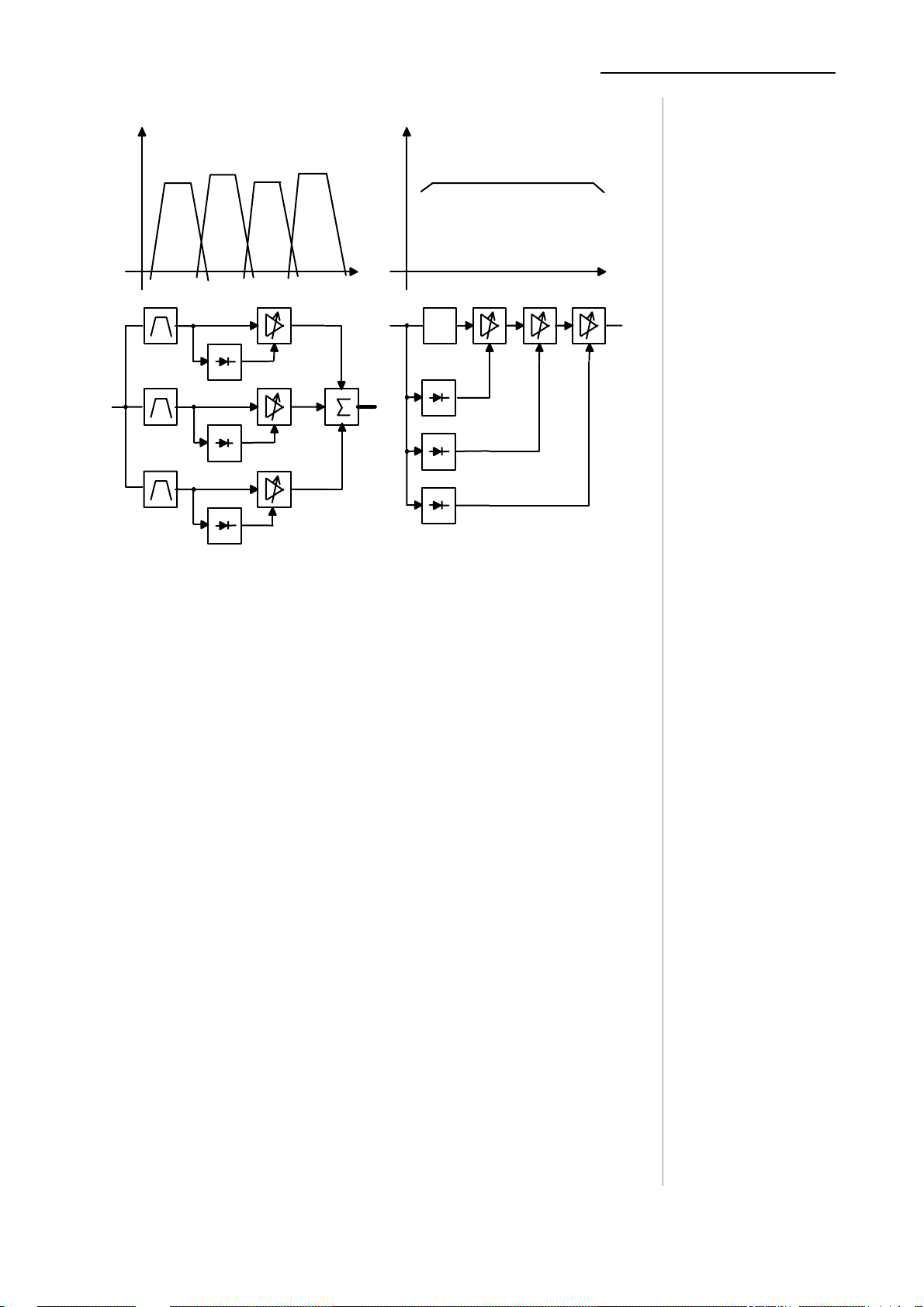
fig. 1:
basic principles of
dynamic range
processors
2
m
Figure 1 shows the basic principles of dynamic range processors.
The compression of the programme signal takes place evenly over
the entire range and not only at the upper end above a certain
threshold level. Dynamic structures of the input signal (e.g. musical
dynamic evolutions) are converted proportionally so that even after
compression the ratios are maintained, only slightly condensed,
leaving on the whole a transparent, seemingly uncompressed s
ound impression.
Compression (reduction of the dynamic range of the input signal to
match the dynamic range of the storage or of the transmission
system) is partly achieved by increasing the level of low level
signals, the lowest of which might otherwise be below the noise floor
of the audio system. The lower the input signal level the higher the
additional gain applied to that input signal by the compression
processing will be.
Independent of the compression ratio , a maximum gain of the
compressor can be set, so that there can be no inadmissible increase
of background noises during signal pauses (e.g. live atmos, airconditioning, hum and noise).
Below an adjustable threshold level an expander can be activated
which can lower the amout of noise signals.
compressor
compression gain
expander
1-3
Page 10
1. THE DESIGN OF THE DEVICE
)
)
g
)
)
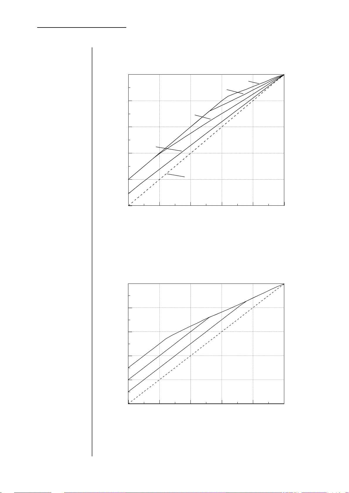
fig.. 2:
static
characteristics:
compressor
static characteristics: co mpressor
output level d02 (dBFS
0
2.0 : 1
1.6 : 1
-10
1.3 : 1
-20
1.1 : 1
-30
fig. 3:
static
characteristics:
compressor
-40
-50
-50 -40 -30 -20 -10 0
compression gain: max. 10 dB
parameter: ratio
static characteristics: compressor
output level d02 (dBFS
0
-10
-20
15 dB
off
input level (dBFS
1-4
-30
-40
10 dB
5 dB
off
-50
-50 -40 -30 -20 -10 0
input level (dBFS
compression gain: max. 15 dB
parameter: compression
ratio: 1.6 : 1
ain
Page 11

1. THE DESIGN OF THE DEVICE
The usable dynamic range for digital recording is determined at the top
by the highest possible digital signal (full scale) and at the bottom by
the lowest possible digital resolution. This range cannot be fully
exploited when using a conventional analog-digital converter caused
by the necessary headroom of 6 ... 10 dB to prevent over-level of the
signal wich could otherwise occur.
This headroom of 6 .. 10 dB reduces the signal to noise ratio by the
same amount even if a high quality A/D converter with 18 or 20 bit
resolution is used.
It is therefore more important than noise-shaping or other dither
techniques to use primarily the maximum of available digital
dynamic range, because this improves most effectively the signal
to noise ratio.
The d 02 digital dynamics processor offers a unique combination of a
24 bit A/D converter and a high quality digital limiter with which a digital
signal free of overload and with maximum digital output level can be
generated.
The A/D converter operates with normal headroom to avoid overload.
Then in the digital domain the level of the signal is increased to the point
where the limiter begins to control the level.
Any possible overload is corrected inaudible by the excellent audio
quality of the digital limiter.
1.3.
A/DConversion with
Digital Full Scale
Level
1-5
Page 12

Page 13

2. INSTALLATION
INSTALLATION
The digital dynamics processor d02 is a device under the safety
category Schutzklasse 1 in keeping with the VDE 0804 standards and
may only used with power supply installations built according to
regulations.
Check the voltage details printed at the rear panel are the same as
your local mains electricity supply.
All input and output connectors of the digital dynamics processor d02
are arranged in functional groups on the rear panel.
POWER INPUT
IEC mains input connector 100-240V, 50/60 Hz with integrated fuse
REMOTE
for optional serial remote interface RS-232 input and output
connector: 15pin SUB-D, male
DIGITAL INPUTS AND OUTPUTS
AES/EBU
input and output for AES/EBU standard format
input: XLR female panel jack
1- open, 2-3 signal, balanced, max. 5 Vpp
output: XLR male panel jack
1- open, 2-3 signal, balanced, max. 5 Vpp
S/PDIF
digital format for semi-professional use
When a signal is present at the AES input at the same time it has
preference over SP/DIF
Input and output : RCA socket
OPTICAL
Optical interface for digital audio signals, (do not use input together with
SP/DIF input)
Input and output : TOSLINK
EXT SYNC
Word clock input for external synchronisation
Input and output: BNC, (TTL-level)
model d02
230 V
50 Hz
200 mA
REMOTE
AES/EBU S/PDIF
IN
OUT
Nr
IN
OUT
OPTICAL
EXT SYNC
DIG OUT
STATUS
CON
24
PRO
16
20
BIT
LEFT R IGHTLEVEL
2
2.1.
Power Supply
2.2.
Connections
ANALOG OUTPUTANALOG INPUT
LEFT RIGHTLEVEL
2-1
Page 14

2. INSTALLATION
2.3.
Switches for
configuration of
the unit
ANALOG INPUT
Analog input to 24 bit A/D-converter
Input electronically balanced, XLR connector female
adjustable level ( +12...+22 dBu for digital full scale)
ANALOG OUTPUT
Analog output from 24bit D/A-converter
Output electronically balanced, XLR connector male
adjustable level ( +6...+22 dBu for digital full scale)
Following switches in the mode field at rear panel are used for
configuration of the unit.
STATUS Setting of sended channel-status-bits on digital
output by using of analogue input at any salmple rate.
Channel status bits
are defined in the AES/EBU data stream.
With the digital dynamics processor d02 it is possible to transmit
this information without changing or to set these information
defined.
(Sometimes it is helpful to change the channel status, f.i. if following units
don’t want to accept incoming signals.)
If using digital input of d02 unit is transparent for channel status
information. There is no changing or modification of it possible.
Channel status information at digital output is the same like
original digital input signal.
PRO selection of professional mode.
CON selection of consumer mode.
DIG OUT Selection of dither mode for reduction of digital
output word length.
16 BIT Dither for reduction to 16 bit word length
20 BIT Dither for reduction to 20 bit word length
24 BIT Signal without dither (unreduced 24 bit word
length)
2-2
Page 15

2. INSTALLATION
The static characteristics of the processor d 02 are related to the digital
reference level.
This internal digital reference level is the maximum output level for the
limiter and the reference level for the static compressor characteristics.
The rotation point for the compressor characteristics with zero gain is
allways situated at the internal digital reference level.
In order to adjust the digital reference level it is necessary to
change the operating mode of the unit as follows. Hold down the
display button continuously for a few seconds and the unit will enter
digital reference level adjustment mode. Pressing the INC or DEC
buttons on can change the digital reference level in the range of 0 dBFS
till -15 dBFS.
It is possible to store two different digital reference levels, one for
use when the analog signal input is selected and another different
setting for use when the digital input signal is selected. When
changing the input selection between analog and digital the required
reference level setting is automatically selected. So it is very easy to
optimize levelling and headroom of the model d02 for different
applications in analogue or digital mode.
For a digital mastering and transmission the output level should be the
maximum, i.e. the digital reference level should be 0dBFS.
When working with analog inputs it is very important not to overload the A/D
convertor (ADC), in order to ensure that the ADC always provides accurate
linear conversion of the analogue input signal to the digital audio signal which
is used for internal processing.
The analog input gain of the d02 should be set so that the maximum possible
studio output level which will occur in practice must not overload the A/D
converter.
When using the analogue output the analogue output gain following the digital
to analogue converter must also be adjusted so that the internal digital
reference level (maximum digital level which can be output by the digital limiter)
corresponds to the maximum analogue level desired for the recorder or
transmission line. Input a continuous signal such as a tone which is large
enough for the limiter to start to operate and for the maximum output level to be
output. The level on the d02 output level meter should correspond to the
internal digital reference level which was set. Then adjust the analogue output
gain to get the desired maximum analogue output level.
The calibration of the reference level should meet the maximum level of the
transmission line or the transmitter. The internal reference level (limiter
maximum output level) is always the absolute maximum level which the d02 will
output.
2.4.
Setting the Digital
Reference Level
2-3
Page 16

Page 17

3. CONTROL AND DISPLAY ELEMENTS
CONTROL AND DISPLAY
ELEMENTS
All functions of the digital dynamics processor d 02 are
activated by buttons. The front panel shows easily recognizable
function groups.
By pressing the left button in the input section the required input signal
can be selected. Each time the button is pressed the input selection is
changed and one of the three LED's above the button lights to show
the newly selected input.
When the AES LED is lit the unit processes the AES/EBU format digital
audio signal applied to its AES/EBU input connector.
When ANALOG INT LED is lit the unit processes the analogue input audio
signal aplied to its analogue input connectors, and the sampling frequency
at which the A/D-converter operates is generated internally.
When ANALOG EXT LED is lit the unit uses the same analogue input
audio signal as when ANALOG INT is selected, but now the sampling
frequency at which the A/D converter operates is determined by the
external word clock or AES/EBU input signal which is fed into the unit.
To the right of the input indicator are three LEDs which shows the sample
rate of the selected input. If a given external digital signal (input signal or
wordclock) has the correct sample rate, the device automatically
synchronizes to that frequency and a yellow light appears on the LED. All
LEDs will blink red if the input signal is lacking or the sample rate is outside
the admissible tolerance range.
With internal synchronisation (ANALOG intern) the sample rate display is
green and the frequency can be changed with the button below.
3
input
3-1
Page 18

3. CONTROL AND DISPLAY ELEMENTS
preset
gain
Press the PRESET button to select the one of the four operating
programs of the unit which best corresponds to the kind of audio
programme material which is being processed. Each operating program
has optimum values of dynamic control characteristics (such as attack
and release times etc.) for a different type of programme material.
in stereo mode (loop function) in 2-channel mode (loop function)
1 - universal 5 - universal
2 - popl music 6 - pop music
3 - speech 7 - speech
4 - live 8 - live
To change preset group hold down the display button continuously for a
few seconds and the unit will enter the stereo/2-channel setting and the
internal digital reference level setting mode. The PRESET and the GAIN
display flashes and and the GAIN display shows the digital reference level.
The STEREO/2-CHANNEL mode can now be changed pressing the
SELECT button. With every tip the unit toggles between the selected
program in stereo or 2-channel mode. If you leave this setting function you
can select your working program like described above.
The INCrement and DECrement buttons allow a linear amplification of the
digital input signal. The selection of gain levels takes place in steps of 1 dB
and has a range from -6 dB ... +15 dB. Each time the button is pushed
there is a change of 1 dB. Holding down the INC or DEC button continously
leads to a continuous change in gain until the respective end value is
obtained. When the gain level reaches 0 dB there is a short pause to avoid
negative gain (attenuation) being accidentally activated.
3-2
Page 19

3. CONTROL AND DISPLAY ELEMENTS
The expander THRESHOLD can be changed upward or downward with two
buttons and is visible on the LEDs above them. Four expander thresholds (-60
dB, -50 dB, -40 dB, -30 dB) can be selected. The threshold level is related to
the choosed digital reference level.
In the OFF position the expander function is switched off.
The activity of the expander is indicated with a red LED in the display
gain reduction.
The compression ratio is adjusted by pressing the RATIO button and the
currently selected ratio is shown by the lighting of the appropriate LED above
the RATIO button.
One of four different ratios can be selected (1.1 : 1, 1.3: 1, 1.6 : 1, or 2 : 1).
There is also a compressor off position where the compressor function is
turned off. In this case none of the ratio LEDs will be lit.
Compression is partly achieved by increasing the level of low level signals,
(the lowest of which might otherwise be below the noise floor of the FM
transmission system). The lower the input signal level the higher the
additional gain applied to that input signal by the compression processing will
be. The maximum amount of gain applied to a low level signal can be
adjusted independently of the compression ratio. Press both the RATIO
buttons at the same time until normal gain display will be switched off.
A red LED will light in the compressor gain display which indicates the
maximum value. This value can be changed with the keys INC and DEC in
the range of 2 dB ... 15 dB.
expander
compressor
maximum compression
gain
3-3
Page 20

3. CONTROL AND DISPLAY ELEMENTS
limiter
bypass
The limiter limits the maximum output signal level of the d02 precisely to
the set digital reference level. (see also 2.4., and, for details of setting the
digital reference level, see under "display"). The limiter should be always
active to ensure that output level of the d02 never exceeds the preset
digital reference level.
The LED shows a red warning signal when the limiter is turned off.
The limiter works with a look ahead time (signal delay) of approx. 2 ms.This
delay time is present even when the limiter is turned off.
Two different reference levels can be set, one reference level for use when
using a digital input signal, and another for use when using analogue input.
In the bypass mode (corresponding LED lits red) the digital signal is passing
unprocessed through the DSP to the output. The signal delay time of approx.
2 ms is also effective in bypass mode.
The bypass function is not a relay bypass and is therefore not effective when
the device is turned off from mains power.
3-4
Page 21

3. CONTROL AND DISPLAY ELEMENTS
The two channel LED display has three display modes (input level, output
level and gain change). Press the button in the display section to change
the display mode. The selected display mode is indicated by the lighting of
the appropriate LED above the display button and to the left of the display
meters. For better visibility each display mode has its own LED colour and
level meter colour.
Green shows the input level and yellow the output level. The scale located
between the two bars indicates the levels. The display which ranges from -50
... 0 dBFS (dB Full Scale) refers to the digital reference level, with a
resolution of 2 dB in the upper section. This does not allow a precise
adjustment, but it does give an indication of the existence and the level of
digital input and output signals.
A peak hold function is available for input and output which makes improved
registration of a momentary peak level possible.
If excessive level at the input occurs when the input level display is selected
(if digital audio samples at the maximum permissable positive or negative
sample value occur at the digital input) then the red clip-LED at the
extreme right-hand end of the level meter lights up and indicates overloads
which are already present in the input signal.
When viewing the OUTPUT level the clipping LED does not light since
the limiter is ON and ensures that the maximum output signal level can not
exceed the preset reference level.
The level meter display is a digital meter without integration time, and
records every successive digital sample value.
The third display mode, gain change, shows the current control levels of
the limiter and compressor in dB.
The compressor works to reduce overall dynamic range by insertion of
additional gain for lower level signals (ie no gain reduction). The scale
above the upper meter bar shows the additonal gain inserted by the
compressor. Lighting of LED's in the meter starts on the left and moves
torwards the right as more additional gain is applied.
The limiter works to reduce the level of high level input signals so that they
do not exceed the preset reference maximum level. The scale below the
lower meter bar shows the level reduction by the limiter. Lighting of LED's
in the meter starts on the right and moves torwards the left as the amount of
level reduction (limiting) required increases.
A red LED is visible in the compressor gain display , which indicates the
maximum permissable value of compressor gain. This value can be
changed in the range +2dB to +15dB (see section on operation of the
compressor on page 10 for details of how to change the maximum
permissable compressor gain).
display
3-5
Page 22

3. CONTROL AND DISPLAY ELEMENTS
Setup selections
using display key
The DISPLAY button has a second function in addtion to changing the
display mode. It is used for setting the internal digital reference level, which is
the maximum output level which the limiter will allow to be output by the unit.
Hold down the display button continuously for a few seconds and the unit will
enter internal digital reference level setting mode. The GAIN display flashes
and shows the digital reference level.
The maximum output level permissable for the unit (internal digital reference
level) can now be changed in 1dB steps within the range -15dBFs to 0dBFs
by pressing the INC and DEC buttons. The reference level to be used when
using the analog input and the reference level to be used when using the
digital input can be set independently.
3-6
Page 23

4. FUNCTIONAL DESCRIPTION
FUNCTIONAL DESCRIPTION
After switching the power on, the digital dynamics processor d02
automatically chooses the settings used before the power was turned
off.
All parameters used, e.g. input, preset, gain, compressor, expander
and display, are stored and re-applied. The only exception is the limiter
which, as a safety function, is always activated when the power is
switched on.
The device is capable of processing digital audio signals as well as
analog audio signals. The unit accepts an AES/EBU format digital
audio signal. In the case of a digital audio input signal being
processed the internal sampling frequency of the unit is
automatically synchronised to that of the digital input signal. The
sampling frequency may be any frequency in the range 30KHz to
50KHz. The d02 directly measures the actual sampling frequency of
the AES/EBU input signal with a frequency counter. It does not rely
on the indicated sampling frequency of the AES/EBU input signal,
which is contained in the signals "channel status" data, being
correct.
If the measured input signal sampling frequency is one of the
standard frequencies (32kHz, 44.1kHz or 48kHz) then a
corrresponding LED will light yellow in the input section on the units
front panel. Continuous lighting yellow of an LED also indicates that
the digital input signal is a valid AES/EBU digital audio signal which
the d02 can synchronise to properly.
If AES digital input is selected but the d02 can not synchronise
properly to a supplied AES/EBU input signal (for example because
there is no valid input signal or because the input signal has a
sampling frequency outside the admissable tolerance range)
then all three "sampling frequency" LED's in the input section of the
d02 front panel will flash red. Digital audio input signals in the
standard AES/EBU format pass from the AES/EBU input connector
through a transformer (as specified by the AES/EBU standard) to
the AES/EBU interface circuitry. The AES/EBU input circuitry
derives the d02's internal sampling frequency from the AES/EBU
input signal and seperates the audio data in the AES/EBU bit
stream from additional control bits, such as channel status data bits
(C-bit) and user bits (U-bit). The audio sample data is converted
from AES/EBU format into the d02's internal digital format for
processing. Data in AES/EBU control bits (C-Bit, U-Bit) will be
passed from the AES/EBU digital input to the AES/EBU digital output
unchanged.
4
Power-on Setting
Digital input signals
Digital input signals
- sample frequency
Digital input signals
- AES/EBU
4-1
Page 24

Digital input signals
- S/PDIF
A/D-converter
Sample rate
External
synchronization
The processing of digital audio data in the consumer format S/PDIF is
also possible. If signals are present at both the AES/EBU and the
S/PDIF inputs at the same time, the AES signal automatically has
priority.
Analog audio input signals can be fed into the unit via the analog
input XLR connectors and first pass through an electronically
balanced analog input amplifier, then to an Analog to Digital
converter (ADC). The gain of the electronically balanced analogue
input amplifier can be adjusted, using potentiometers on the rear
panel. The maximum analog input level , which will correspond to
a digital full scale (0dBFs) digital output signal from the internal ADC,
can be set to any value in the range +12dBu to +22dBu.
The standard factory setting of the unit when supplied is that a
programme level of +6dBu at the analog input corresponds to 9dBFs (9dB below maximum possible digitally represented level which
can be output by the A/D convertor). Therefore the maximum
permissable analog input level without clipping when the unit is
supplied is +15dBu.
Both analog inputs are converted into digital audio signals, which can
then be processed by the internal digital dynamics processing.
Conversion is done by a high performance 24 bit oversampling A/D
converter which is manufactured by CRYSTAL Semiconductor. The
analogue to digital converter has a dynamic range of 114dB and is
very linear in terms of both frequency and phase response. Provided
that the maximum permissable analog input level (which will
correspond to 0dBFs (full scale) internal digital input level shown on
the units level meters) is not exceeded the A/D conversion process
should have no signficant influence on the sound quality. The audio
sample data output from the A/D converter is converted into the
d02's internal digital format for processing.
When the input is set to 'ANALOG intern' the sampling frequency
used for the A/D conversion, internal digital processing and digital
output will be generated internally. The sampling frequency (32KHz,
44.1KHz or 48KHz) can be selected with the button in the input
section and is displayed by the lighting of a green LED in the d02's
front panel sampling frequency display. For applications where analog
input is used, but where the AES/EBU digital output of the unit must
be synchronised with another AES/EBU digital audio signal or with a
Word Clock signal, the input selector must be set to ANALOG extern.
The AES/EBU signal or Word Clock signal which the unit is required
to synchronise the sampling frequency of its AES/EBU output with
can be applied to the AES/EBU input connector or to the EXT
SYNC word clock input connector respectively. The sampling
frequency of the external AES/EBU or Word Clock signal (and
hence the operating sampling frequency of the d02) will be
indicated by the lighting of a yellow LED in the d02's front panel
sampling frequency display.
All three LED's in the d02's front panel sampling frequency display will
flash red if the d02 can not synchronise to an external sampling
frequency signal because no signal is connected or because the
connected signal is outside the admissable working sampling
frequency range of the unit (30KHz to 50KHz).
4-2
Page 25

4. FUNCTIONAL DESCRIPTION
The digital audio signal (either an AES/EBU digital input signal or an
analog input converted by the A/D converter) is processed in a Texas
Instruments Floating Point Signal processor with a data width of 32
bits. The use of 32 bit digital audio sample length in calculation
ensures that there is no deterioration in signal quality, even if
AES/EBU digital audio data with the maximum word length of 24 bits
is input into the unit.
The DSP carries out the functions of the dynamics processing, the
linear gain and the emphasis filtering. It measures the input and output
levels and generates data for GAIN CHANGE display. Reading of the
front panel buttons and operation of the front panel display is
performed via a special interface (see also chapter 3.).
One main task of the digital transmission processor d 02 is the
compression of low signal levels. The compression- RATIO expresses
the effects of a change of the input signal in dB on the change of the
output signal in dB.
E.g. a ratio of 2:1 means that a change in input signal of 20 dB causes
a change in output signal of 10 dB. With the choice of a compression
ratio, the intensity of the compression is determined and with it also a
certain compression characteristic (see also fig.2 and fig. 3). The
RATIO parameter is adjusted on the front panel in four steps, from
1.1:1 to 2.0:1. The transition to another characteristic can be carried
out during the running programme. It does not cause any clicking
noises.
The lower the signal level, the higher the gain of the compressor will
be. Independently of compression ratio, the maximum amount of
compression gain can be adjusted so that no inadmissible increase of
background noises (e.g. live atmos, air-conditioning, hum and noise)
may occur during signal pauses.
To set the maximum compression gain press both the RATIO button
and the PROGRAM button simultaneously. A red LED becomes visible
In the compressor gain display , which indicates the maximum value
of compression gain. This value can be changed in 1dB steps over
the range +2dB to +15dB pressing the INC and DEC buttons.
The expander becomes effective when the signal level falls below an
adjustable expander threshold. It is possible to select four thresholds
from -60 dB...-30 dB.
If the level falls below the threshold , the gain is steadily decreased up
to -15 dB. The downward regulation of the expander is achieved just
as quickly as the upward regulation of the compressor, thereby
compensating the resulting increase in signal noise.
For the dynamics functions, particularly the algorithm of the limiter, a
signal delay of approx. 2 ms is built in. This delay makes it possible to
arrange the algorithm of the limiter in such a way that the control
mechanism is activated before maximum level is reached. Within the
rise time of the signal the peak level is recognised and the maximum is
calculated in such a way that full scale level is reached precisely
without causing clipping.
Digital signal processor
compression
Maximum compression
gain
expander
Look ahead limiter
4-3
Page 26

D/A-converter
The processing of digital audio signals in the signal processor requires
a machine-specific format. Special interface circuits are therefore
available to convert to standardised digital interface formats.
Additionally, an analog output signal is available. A stereo - D/A
converter with a resolution of 20 bits generates an analog signal with
very high audio quality. This signal is fed to balanced output
drivers.The gain of the balanced analog output driver circuit for each
analog output can be adjusted on the rear panel, so that the
maximum possible analog output level can be adjusted to be any
value in the range from +6dBu to +22dBu.
(The maximum possible analog output level here is the analog output
level when the output level meter shows 0dBFs full scale digital level
and the D/A converter is being fed with a digital signal at 0dBFs the maximum possible full scale level that can be represented
digitally).
If the internal digital reference level is reduced to below 0dBFs then
the maximum analog output level will be correspondingly reduced by
the action of the limiter.
For example if the internal digital reference level is reduced to 9dBFs (9dB below the maximum possible level that can be
represented digitally) then the actual maximum digital level that will
be received by the D/A converter will be 9dB below the maximum
possible digital level. In this case the range of adjustment for
maximum analogue output level will be -9dBu to +13dBu.
The design of the electronically balanced analog output drivers is
such that the output level is maintained even when driving an
unbalanced load.
4-4
Page 27

5. APPLICATION NOTES
APPLICATION NOTES
It is possible to choose one of eight different control
characteristics for the dynamics processor. Each of the four
different sets of control characteristics provides ideal dynamics
control for a different type of programme signal as follows:
s
1 - universal 5 - universal
2 - pop music 6 – pop music
3 - speech 7 - speech
4 - live 8 - live
Selecting a particular preset sets up the optimum parameters of the
dynamics processor (attack and release times, threshold levels
and interactions between the multiple signal dependent control
circuits) for a particular kind of programme material.
For example, generally speaking, release times are longest when
using the universal setting and shortest when using the live setting.
(In order to understand the basic Multi-loop principle of the Jünger
Audio dynamics processors please refer to chapter 1.2).
Fixed presets containing optimised parameters for different types of
programme signal are used because, with the great number of
parameters used and the interactions of parameters used in
different stages of the multiloop system, changing of individual
parameters by the user could cause problems.
If the audio signal was recorded with emphasis, the additional
information of the digital input signals contains a definite emphasiscontrol-bit in the AES/EBU or SP/DIF format. This is sometimes the
case in older recordings because it slightly improved the signal-tonoise ratio of currently used analog-digital converters. Similar to noise
reduction methods in analog magnetic tape recording, the higher
signal frequencies are raised prior to recording, and subsequently
lowered in playback, causing a lowering of the higher frequency noise
level.
If such a signal is compressed or limited in a dynamics processor,
problems will occur as the peak levels for high frequencies do not
represent the true values. The dynamics processor causes a change
in peak levels which would, however, lead to a change in the treble
content after passing through the external deemphasis filter.
Prior to dynamic processing a signal recorded with emphasis must
therefore be linearized, i.e. pass through a digital deemphasis filter.
This filter in the d 02 is automatically switched on if the corresponding
control bit is set in the AES/EBU or S/PDIF format. If the filter is
turned on, the colour of the AES input LED will change to red.
tereo mode 2-channel-mode
5
5.1.
Presets
5.2.
Processing signals
containing
emphasis
5-1
Page 28

5. APPLICATION NOTES
5.3.
Working with
headroom
fig. 5:
Static
characteristics:
Compressor/
Limiter with -9dBFS
Digital Reference
Level
5.4.
Influence of signal
delay time
The static characteristics of the d 02 (see also fig. 2) usually refers to
the digital reference level 0 dBFS (dB Full Scale). This is useful for
most applications of the dynamics processor as the on-following
digital recording system is supposed to be balanced down to the final
bit.
For applications using headroom the d 02 can be adjusted to another
reference level of 0 ... -15 dBFS in steps of 1 dB. The limiter threshold
and therefore the maximum output level are determined by this digital
reference level. This value is then also the reference for the expander
and limiter threshold values. The static characteristics for a reference
level of -9 dBFS are illustrated in fig. 5.
The adjustment of the device to this reference level is achieved with
pushing DISPLAY and GAIN buttons at the same time (see also
chapter 2.4. and 3.).
output level d02 (dBFS)
0
static characteristics: compressor
-10
2.0 : 1
1.6 : 1
Headroom 9 dB
-20
1.3 : 1
-30
-40
1.1. : 1
off
-50
-50 -40 -30 -20 -10 0
input level (dBFS)
compression gain: max. 10 dB
parameter: ratio
digital reference level: -9 dBFS
The audio signal delay through the dynamics processor is approx.
2ms due to delaying of the audio signal using internal memory. A
small delay is deliberately introduced to the audio signal in order to
allow limiter and compressor algorithms which can 'preview' the
audio signal before changing it. That is the signal curve can be
changed before maximum level is reached. (For further details see
chapter 1).
This delay must be considered before attempting to mix signals
processed by the dynamics processor with other undelayed signals.
5-2
Page 29

5. APPLICATION NOTES
When mixing together a delayed signal and a direct signal there may
be cancellation of the signal waveform at some frequencies and reinforcement of the waveform at other frequencies (comb filter effect).
Corresponding 2ms delay of direct signals should therefore be
carried out before mixing them with delayed processed signals.
Signal compression and the loudness enhancement of the digital audio
signal resulting from it can be achieved by combining two dynamic
range control processes: firstly, the compression achieved by
increasing small and medium signal levels and secondly, linear
amplification combined with the inaudible limitation of individual,
remaining peak levels with the limiter.
In the gain change mode the operation of compressor and limiter can be
observed on the display. For smaller signal levels the compressor
causes additional amplification which however decreases the higher the
signal level is . With full scale levels the compressor is practically
ineffective so that even an increase of the RATIO will have no effect.
If you now increase the linear amplification GAIN, individual peak levels
are raised above the limiter threshold and limited inaudibly. All other
signal components can however be increased. If the gain is too large
also medium levels are treated by the limiter, which means that the
limiter then reduces the signals continually and again reduces the
additionally applied amplification.
The display for Limiter-Gain-Reduction should be in the region of 0...-
6...-8 dB and should not light up red continuously, so that a dynamic
limitation only applies to signal peaks. Then the signal compression and
therefore also the increase of loudness is at its most effective.
At the end of postproduction the material must be prepared for copy on
COMPACT DISC. The information of a 24 bits signal is not more
storable linear. One must shorten 24 bits data word to 16 bit word
length. The practice offers several procedures for it.
In the simplest case, the last bits are cut off - truncation. One requires
no further processing to this, it is enough to record a 20or 24 bits signal
direct on a 16 bits storage medium. In this case, a not unimportant
quantization mistake however results, the part of the harmonious
distortions increases. Single numeric roundoff of the signal to 16 bits
reduces this mistake. Nevertheless, the result will normally be worse
than the data by the same original analog signal converted with a good
16 bit ADC.
In order to receive a better quality during cut down the data to 16 bit one
must redithering the material with corresponding devices. Here the
device is calculating random numbers (dither signal) and add a different
random number to every sample. Then it will be cut off to 16 bit. As a
result, the bit with least weight (LSB) is put in such a way that it
corresponds best to the information of the last bits following available
ones no more and makes less distortions as hissing in the signal.
5.5.
Selection of
parameters to
increase loudness
5.6.
Redithering Reduction of word
length of digital
output signal
truncation
redithering
5-3
Page 30

5. APPLICATION NOTES
noise shaping
Disadvantages of
noise shaping/
redithering
A specific redithering is noise shaping, with that the noise modulation of
the LSB is considering the psycho-acoustic sensitiveness of the human
ear. With it can be enlarged the audible dynamic range of a reformatted
16 bit recording ideally by about 3 bits i.e. to more than 110 dB. To
make this quality audible, the CD must of course be played back with
appropriate monitoring equipment (D/A converter, amplifier) for 20 bit
quality.
The disadvantage of redithering - noise shaping consists in the
restrictions during postproduction. In order to receive the achieved effect
every processing must occur with coefficients which correspond to the
word length of the initial data. At signals processed with noise shaping,
these coefficients would have to be besides filtered in the same manner
like the dither signal. If one can not adhere to these conditions, one
must live with the loss of the effect, in some cases it occurs data losses.
Multiple application of these procedures can even make drop-in and
noises, such as twittering or clicks. Therefore, noise shaping or
redithering should be used only at the end of the process chain, i.e.
during the preparation of the copy master for reproduction.
5-4
Page 31

APPLICATIONS
- mastering of CD, DCC, MD
maximum recording level without clipping
increased programme density and loudness
- digital recording and mixing
increased loudness level (compressor, limiter)
eliminating noise signals (expander)
- FM-Broadcast, TV-Sound
signal conditioning
matching dynamic range of different programme signals
increasing signal loudness level
- limiter for digital or analog transmission links
always digital full scale signal, without clipping
- post production and ADR studios
adjusting dynamic range and loudness level of individual takes,
maximum recording level without clipping
- A/D converter free of overload for general use
high performance 24 bit ADC in combination with digital limiter
digital output signal without clipping
further applications without the dynamic functions
- digital audio format conversion
all digital outputs are available in parallel
irrespective of the input format
AES/EBU + S/PDIF + OPTICAL
- digital deemphasis filter
removing emphasis automatically
emphasis bit in AES/EBU is also removed
- digital-analog converter
high quality 24-bit stereo output signal
balanced line outputs with adjustable output level
6
6-1
Page 32

Page 33

TECHNICAL
SPECIFICATION
sample rate : 30 kHz ... 50 kHz
audio data format : 24-bit (AES/EBU)
24-bit (A/D-,D/A-converter)
AES/EBU
level : 5 Vpp / 110 Ohm, balanced
connector : XLR
input format : AES professional, AES consumer
output format : same as input
S/PDIF
level : 0.5 Vpp / 75 Ohm, unbalanced
connector : RCA
input format : AES professional, AES consumer
output format : same as input
OPTICAL
connector : TOSLINK
A/D-converter : stereo, 24 Bit, oversampling
dynamic range : 112 dB (RMS)
114 dB (A-weighted)
input level : +12...+22 dBu for 0 dBFS, adjustable
input : XLR, floating balanced, 10 kOhm
(optional: transformer balanced)
D/A converter : stereo, 24-bit, oversampling
dynamic range : 108 dB (RMS)
110 dB (A-weighted)
output level : +12...+22 dBu for 0 dBFS, adjustable
output : XLR, floating balanced, 50 Ohm
(optional: transformer balanced)
remote : for connection with d - remote drc01
(optional)
power consumption : approx. 20 W
dimensions : 19 inch, 1 RU, 250 mm depth
digital
input / output
analogue
input / output
general
weight : appr. 4.5 kg
7
7-1
Page 34

8
8. WARRANTY AND SERVICE INFORMATION
WARRANTY AND SERVICE
INFORMATION
JÜNGER AUDIO grants a two-year warranty on the
d02 dynamic range processor
If the unit has to be serviced, please send it,
ideally in the original box, to:
JÜNGER AUDIO - Studiotechnik GmbH
Justus-von-Liebig-Str. 7
D - 12489 Berlin
GERMANY
Tel.: (*49) -30-677721-0
Fax.: (*49) -30-677721-46
operation manual b42, chapter 9 -Warranty and service information- page 9-1
Page 35

KONFORMITÄTSERKLÄRUNG
DECLARATION OF CONFORMITY
Geräteart : Digitaler Dynamikprocessor
Type of equipment : digital dynamics processor
Produkt / Product : d02
Das bezeichnete Produkt stimmt mit den Vorschriften folgender EU-Richtlinie(n) überein:
The aforementioned product complies with the following Europaen Council Directive(s):
89/336/EWG (geändert durch 91/263/EWG und 92/31/EWG)
(changed by 91/263/EEC and 92/31/EEC)
Richtlinie der Rates zur Angleichung der Rechtsvorschriften der
Mitgliedsstaaten über die elektromagnetische Verträglichkeit
Council Directive on the approximation of the laws of the
Member States relating to electromagnetic compatibility
73/23/EWG (geändert durch 93/68/EWG)
(changed by 93/68/EEC)
Richtlinie des Rates vom 19. Februar 1973 betreffend elektrische
Betriebsmittel zur Verwendung innerhalb bestimmter
Spannungsgrenzen
Council Directive of February 19th 1973 concerning electircal
equipment for operation within certain voltage limits
Zur vollständigen Einhaltung dieser Richtlinie(n) wurden folgende Normen herangezogen:
To fully comply with this(these) Directive(s), the following standards have been used:
EN 55022 : 1987
EN 50082-1 : 1993
EN 60065 : 2002
Dieser Erklärung liegen zugrunde : Prüfbericht(e) des EMV-Prüflabors
Interne Vorschriften zur Sicherheits-Prüfung
This certification is based on : Test report(s) generated by EMC-test laboratory
Internal regulations for safety check
MEB Messelektronik Berlin : Kalibrier- und Prüflabor
accredited EMC laboratory
Aussteller / Holder of certificate : Jünger Audio Studiotechnik GmbH
Justus-von-Liebig-Strasse 7
D - 12489 Berlin
Berlin, 18.03.2003 .....................................................................................
(Ort/Place) (Datum/Date) (Herbert Jünger, Geschäftsführer/Managing Director)
Page 36

www.jungeraudio.com
d02
 Loading...