

Page 1
digital audio
modular
C8000
processing system
sync interface
features
• Standard sync module for a C8000 frame
• Internal sync @ 44.1 / 48 / 88.2 / 96kHz
• External sync auto format sensing : AES, Word Clock, Video Reference
• Video Reference :
Black Burst (NTSC or PAL)
Composite Sync (525 or 625)
Tri Level Sync (HD - 720p, 1080i, 1080p)
• Generates a Dolby-E frame sync reference that can be shifted in respect to
the defined video switching point
• Two fully redundant sync inputs
• Synchronous Word Clock output
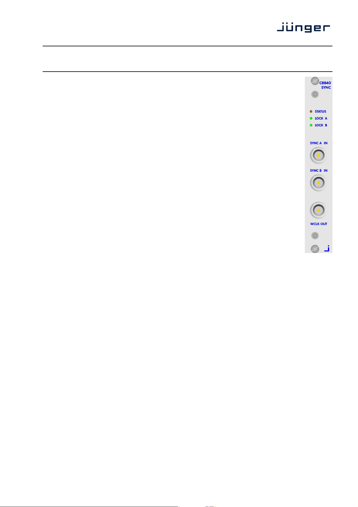
• Front panel status indicator
• Front panel Lock A, Lock B indicator
The C8840 as the heart of a C8000 system. It synchronizes the backplane audio transport to maintain
glitch free hand over of serial audio data between the various I/O and processing modules.
For redundant operation it offers two inputs with automatic switch over. This allows the system integrator
to design a fail over system with independent feeds which may even have different reference formats
(E.g. BB and AES sync).
For Dolby E encoding inside a C8000 frame a frame sync pulse (AKA frame reference) is necessary.
The C8840 extracts such frame sync pulse from the input video reference. A circuit is provided to move
the edge of that reference in respect to the input video frame. I.e. one may align a Dolby E encoded signal
by the accuracy of a video line to the reference switching point.
If no video reference is connected the frame sync pulse will be generated from the internal sync source.
For non video applications like CD mastering or high resolution audio production the C8840 may be
synchronized to audio sample rates of 44.1, 88.21 or 96kHz. Pls. keep in mind that those sample rates
can not be used for SDI (Serial Digital Video) embedding / de-embedding.
The C8840 measures the input format and displays it via the Web GUI status display of the module.
In case of a severe sync problem, the Frame Controller can send a SNMP trap and / or activate a SNMP
GPO. A higher-ranking monitoring system may poll the status of the sync module(s) via SNMP.
Finally there is the feature to set the sync source via presets loaded by a GPI
and to get a GPO for the selected source.
C8840
1/8
Page 2

digital audio
modular
C8000
processing system
sync interface
technical specifications
Internal sync : 44.1, 48, 88.2, 96kHz
SYNC A IN / SYNC B IN : BNC, 75 Ohm
VIDEO : Black Burst, Composite Sync, Tri Level Sync
level : nominal 1V (0,5 … 2Vpp)
stability : < ±100ppm (typ. ±50ppm lt. AES 11, Grade2)
format : PAL / NTSC / HDTV
rates : 625i50 (PAL)
: 525i60 / 525i59,94 (NTSC)
: 1035i 59,94/60
: 1080i/50/59.94/60
: 720p/50/59.94/60
: 1080p/23.98/24/25/29.97/30/50/59.94/60
frame sync pulse : 25 … 30Hz ±1023 lines - generated from video reference
WCKL :
level : TTL, 1 … 5V
rates : 44,1, 48, 88.2, 96 kHz
General
Backplane connector : ref. to DIN41612, 64pin, a+b, male
Power supply : +5V DC
Consumption : approx. 300 mA
Dimensions : 3RU, 4HP, 160mm depth
general remark
For the alignment of the guard band of Dolby E encoded streams, the C8840 provides a frame sync pulse
[see VIDEO-REF at C8611 Dolby E encoder]. It must be derived from a 25 or 30fps (or their fractional
representatives) video reference. If the C8840 is set to internal sync (or falls back to internal sync), the
frame sync pulse will be generated internally. If one provides a frame rate > 30Hz it will automatically
divided by two. This maintains Dolby E encoding but the phase relationship is lost.
Due to the data rates Dolby E data frames will span over two progressive HD video frames.
Dolby recommends to use a HD synchronous black burst derived from the HD master SPG of a facility.
The consequence is that video editing / routing in respect to Dolby E encoded signals can be performed
every second frame only.
stability : < ±120ppm (typ. ±50ppm lt. AES 11, Grade 2)
AES/EBU : AES-3id
level : nom 1V (0,3 ... 1.2Vpp)
rates : 44,1, 48, 88.2, 96 kHz
stability : < ±120ppm (typ. ±50ppm lt. AES 11, Grade 2)
WCLK OUT : BNC, 75 Ohm
level : ≥2,4V @ 75 Ohm
rates : 44,1, 48, 88.2, 96 kHz
stability : typ. ±25ppm internal generator
C8840
2/8
Page 3
digital audio
modular
C8000
processing system
sync interface
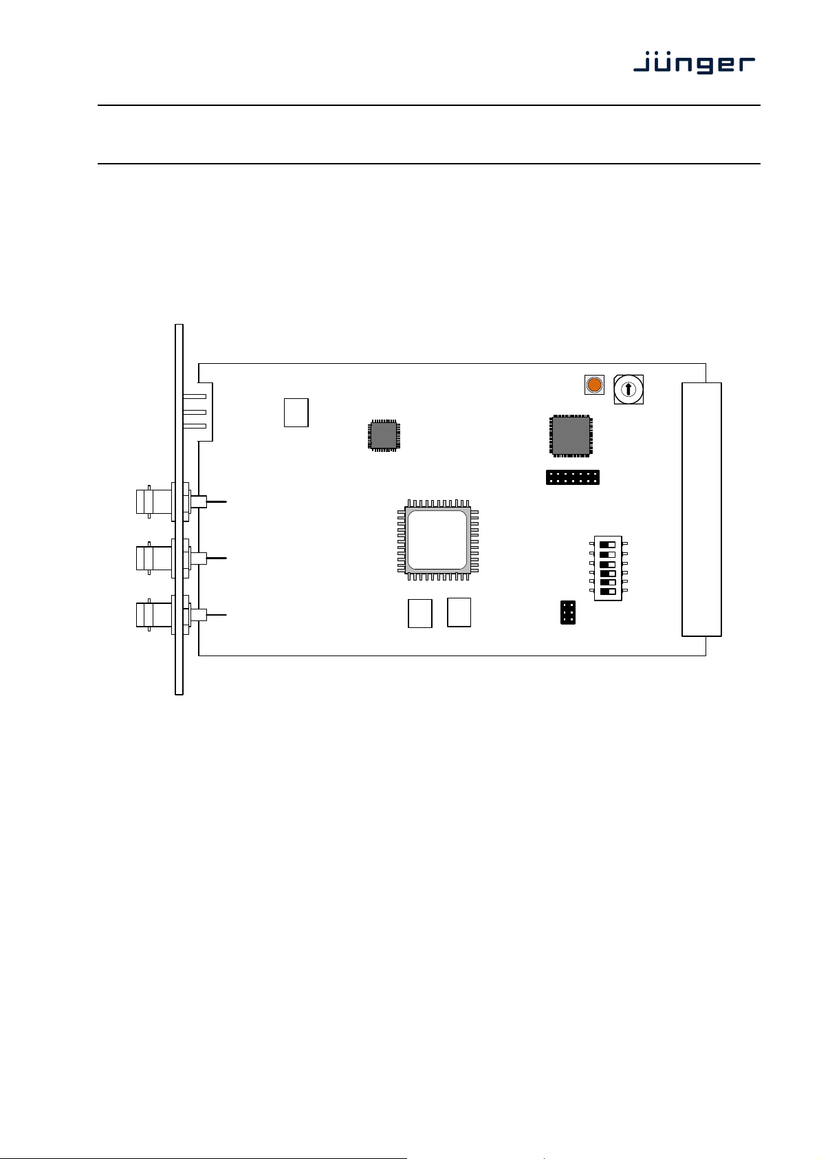
installation
The C8000 frame must be switched off for installation or swapping of a sync module! Without a stable
clock, some interface modules can fall into irregular condition which could destroy parts of the circuits!
The C8840 must be installed in one of the red coloured fitting rails at rear of a C8932 frame, close to the
mains connector(s).
C8840
INIT
ADDRESS
SW1
6:
5:
4:
3:
2:
1:
Setting the CAN address of the module :
ADDRESS [0, 1, 2, 3]
16 position rotary encoder
A C8000 frame employs the CAN-bus for internal communication
and remote control purposes. For proper operation it is necessary
to assign each module its unique ID. To avoid conflicts, the
address scheme of a C8000 system must be planned with care
(see C8000 System Manual for details).
Since the sync module has a special role in a C8000 frame it
resides in a dedicated address room like the C8702 frame
controller. One may install up to four C8840 modules in a C8934
split (island) frame to support four independent services, each with
Dolby E encoding in a progressive HD format.
TERM
ON DIP
1 2 3 4 5 6
3/8
Page 4

digital audio
modular
C8000
processing system
sync interface
Setting the CAN address for special applications :
In standard applications one does not need to set the CAN address of a C8840, simply leave it at
address "0".
In applications for the C8934 split frame, you may need a C8840 for each island to maintain proper
Dolby E encoding in reference to progressive HD video.
To distinguish between the number of C8840s each must have an unique CAN address. Due to the
general address scheme, C8702 and C8840s appear in the top rows of the Web GUI.
The rotary ADDRESS encoder settings translates to the following logical addresses and graphical
positions :
Rotary enc. logical GUI
ADDRESS address row / column
0 0 1st / 1st
1 4 1st / 5th
2 8 2nd / 1st
3 C 2nd / 5th
Here is an example for a C8840 in a C8934 frame that is setup for rotary encoder
ADDRESS #3 (logical C) :
C8840
SW1
1: TERM [ON, OFF]
The CAN bus is a two wire bus that must be terminated at both
ends. On one of the modules in a C8k frame which is able to
terminate the CAN bus, the TERM switch must be set to ON.
The suggestion is to turn it ON for the C8702 and OFF for the
C8840. But for special applications one may turn it on at the
2: Not used – must be OFF
3: Not used – must be OFF
4: Not used – must be OFF
5: Not used – must be OFF
6: Not used – must be OFF
C8840.
4/8
Page 5

digital audio
modular
C8000
processing system
sync interface
operation
Click on the spanner tool of the graphical box of a C8840 in the GUI
to navigate the pages of the C8840:
PRESET
C8840
Load select a preset by name and press <LOAD NOW>.
Save as # select a preset memory number.
Name assign the preset a name (up to 16 digits) and press
<SAVE NOW>.
Preset Clipboard copies the active preset to a clip board, The data may be used
Backup Presets to File creates an backup XML file which may be stored to the PC
Restore Presets from File you can select a backup file from the PC.
by other modules inside the same frame.
5/8
Page 6

digital audio
modular
processing system
DEVICE
C8000
sync interface
C8840
Device Name you can assign the module a name (up to 16 digits) and assign it
Platform shows the hardware platform of the C8840
Parameter Version shows the parameter version of the module controller
FIRMWARE
Controller shows the firmware of the module controller
FPGA shows the actual firmware of the Module FPGA
Bootloader shows the bootloader version
Restart Module <RESTART> performs a warm start (soft reset)
Initialize and Restore <INITIALIZE> restores the factory default values for all
Factory Defaults parameters of the module including all presets. The input bus
Backup Settings and <BACKUP> will put all active parameters and the content of all
Presets to File presets into an XML file. You may store such file on a PC.
Restore Settings you may select <browse> a matching XML file from a PC.
and parameters from File <RESTORE> will overwrite all active parameters and the content
by pressing <CHANGE NAME>.
assignment will be set to S01 … S04, The outputs are turned
OFF and the bus drivers will be disabled.
of the presets by the content of the backup file.
6/8
Page 7

digital audio
modular
C8000
processing system
sync interface
PARAMETERS
Connect a clock source with SYNC A IN and an other one with SYNC B IN
The dedicated LOCK A LED turns from red to green to indicate that this input is in use right now and
the C8000 system timing is locked to that source. The LOCK B LED slowly flashes green to indicate
that the input is locked to that reference but it is not in use for the C8000 system clock :
C8840
SYSTEM CLOCK selection of the C8000 system clock
Sample Rate (kHz) [44.1, 48, 88.2, 96 FOLLOW]
Allow 96kHz [ON, OFF]
Fallback Sample Rate (kHz) [44.1, 48, 88.2, 96]
Fallback Video Rate (fps) [25, 29,97, 30]
Sync Source Priority
Sync A [ON, OFF]
Sync B [ON, OFF]
Sync Internal [ON, OFF]
Fallback on Sync Error Internal
Video Sync Shift
Video Sync [-1023 … 0 … 1023]
Shift Offset (lines)
7/8
Page 8

digital audio
modular
processing system
GPI/O
C8000
sync interface
C8840
GPIs are useful if you want to recall settings remotely (e.g. by presets).
The C8k frame can handle 127 different GPIs. You must assign a
unique number to the respective function. Such numbers will be
generated by the brc8x Broadcast Remote Controller or by a GPI/O
interface module. If the C8840 receives such a number via the CAN
GPOs (Tallies) may signal the status of a module. If you load a preset the C8840 puts
bus, it will load the respective preset for example.
the assigned number on the CAN bus so a C8817 GPI/O module may
turn on a relay or the brc8x may turn on button LEDs (see respective
manuals for details). The 8817 relays have NO (normally open) as well
as NC (normally closed) contacts. This allows for easy interconnection
with more generic monitoring equipment or very simple push button
controls.
8/8
 Loading...