

Page 1
digital audio
modular
C8000
processing system
Dolby® E / D / D plus decoder
Features:
• Dolby® D / D+ / E decoding
• Supports Audio Description
• Pro Logic II decoding and encoding
• Metadata generator
• RDDD-6 metadata output
• Unbalanced AES input for Dolby® encoded signals
• Automatic format detection (Dolby® D / D+ / E / PCM)
• Automatic PCM pass through
• Unique Dolby® subset metadata transport (via AES USER Bit)
• 2Ch Delay for PCM audio and / or metadata
• Program monitoring down mix output
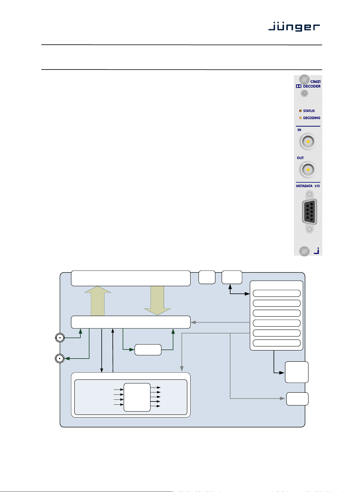
Block diagram:
C8621
BACK PLANE audio interface
32 bus Lines (I/O, 2/ 8 Ch mux)
Audio router / Metadata – extractor / – inserter
IN (encoded)
8 Ch
OUT (downmix)
DOLBY® CAT1100 OEM Board
Ch 1/2
Ch 3/4
Ch 5/6
Ch 7/8
C8621 Carrier Board
SYNC
System sync
inertface
Audio
Dolby E
Dolby D
Dolby D+
decoder
Delay
Ch 1/2
Ch 3/4
Ch 5/6
Ch 7/8
Downmix
10 Ch
CAN-BUS
interface
MODULE CONTROLLER
Frame Controller
Preset
management
GPI/O
handling
Metadata
processor
Metadata
generator
Front Panel
status display
Metadata out
commmunication
STATUS
LED
DECODING
LED
METADATA
I/O
C8621_manual_EN_150624.doc
Page 2
19
digital audio
modular
C8000
processing system
Dolby® E / D / D plus decoder
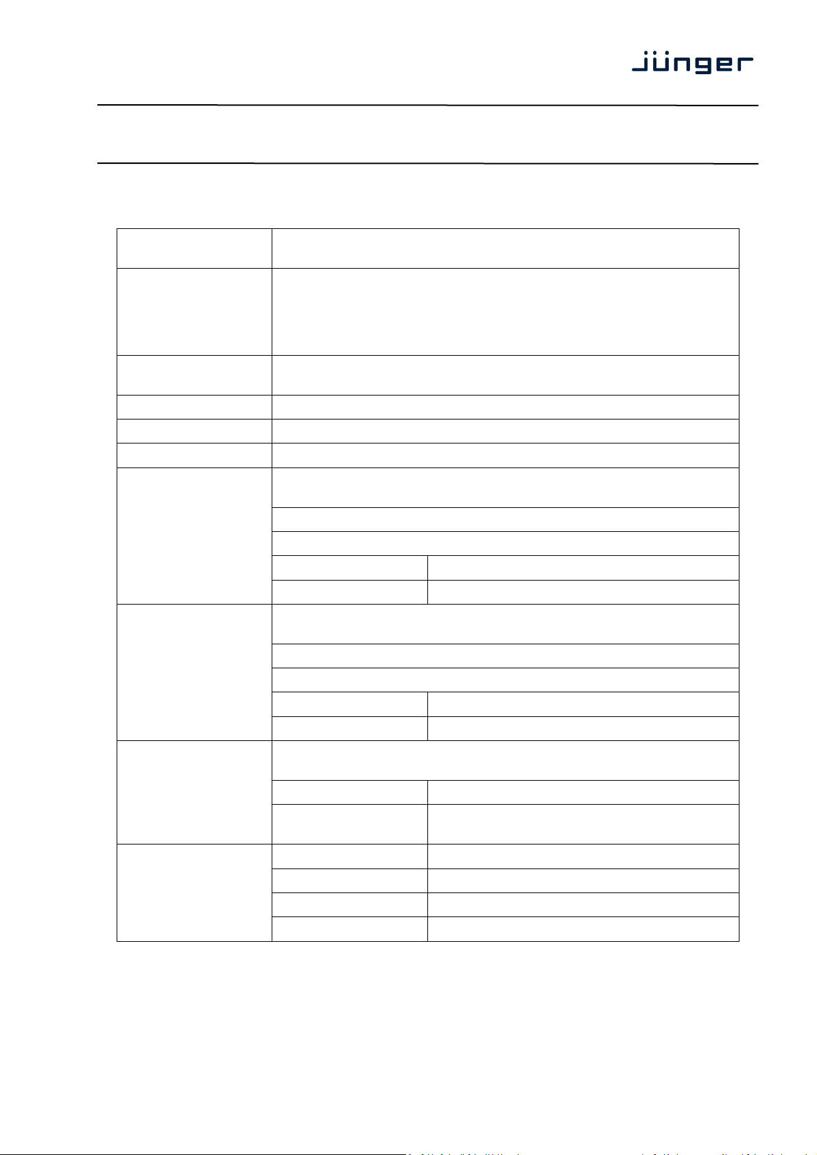
Technical data:
Standards Decoder for compressed multichannel audio supporting proprietary Dolby®
formats.
Audio Formats PCM (24bits)
Dolby® Pro Logic II
Dolby® E (16/20 bits, video frame rates: 23.975, 24, 25, 29.97, 30fps)
Dolby® D
Dolby® D+ (Audio Description supported)
Audio Channels 8 inputs (2 compressed or up to 8 PCM)
12 outputs (8 decoded audio + 2 downmix + 2 delayed)
Channel Modes up to 7.1
Audio Sample Rate 48kHz
Audio Delay 0 … 340ms for 2 channels, user settable and routable
C8621
AES/EBU Input
(External)
AES/EBU Output
(External)
Metadata Output
(External)
Decoding Latency
Relevant specifications comply with AES3-X-2009, IEC 60985 and
AES11-2009
2 channels (1 stereo input), BNC connector
24bits, PCM or compressed audio, decoder input
Impedance 75Ohm
Input level 0.3 … 5Vpp @ 75Ohm single-ended
Relevant specifications comply with AES3-X-2009, IEC 60985 and
AES11-2009
2 channels (1 stereo output), BNC connector
24bits, PCM audio, downmix / Pro Logic II, decoder output
Impedance 75Ohm
Output voltage 1Vpp (typ.) @ 75Ohm single-ended
Relevant specifications comply with SMPTE RDD6-2008 (Dolby®
Metadata).
Connector type D-Sub9 connector female
Output conditions 3Vpp (typ.) @ 110Ohm differential, RS485,
115kbaud
Dolby E 1 video frame, depending on signal
Dolby D 64...67ms (nom.), depending on mode
Dolby D+ 64...67ms (nom.), depending on mode
PCM 20ms … 1 video frame, depending on mode
Page 2/
Page 3
19
digital audio
modular
C8000
processing system
Dolby® E / D / D plus decoder
Power Supply 5Vdc (4.75 … 5.25V), max. 800mA
Dimension 3RU, 4HP, 160mm depth (DIN41612 backplane connector)
Environmental Operating temperature 0 … 40ºC,
Non-operating -20 … 70ºC,
Humidity < 90%, non-condensing
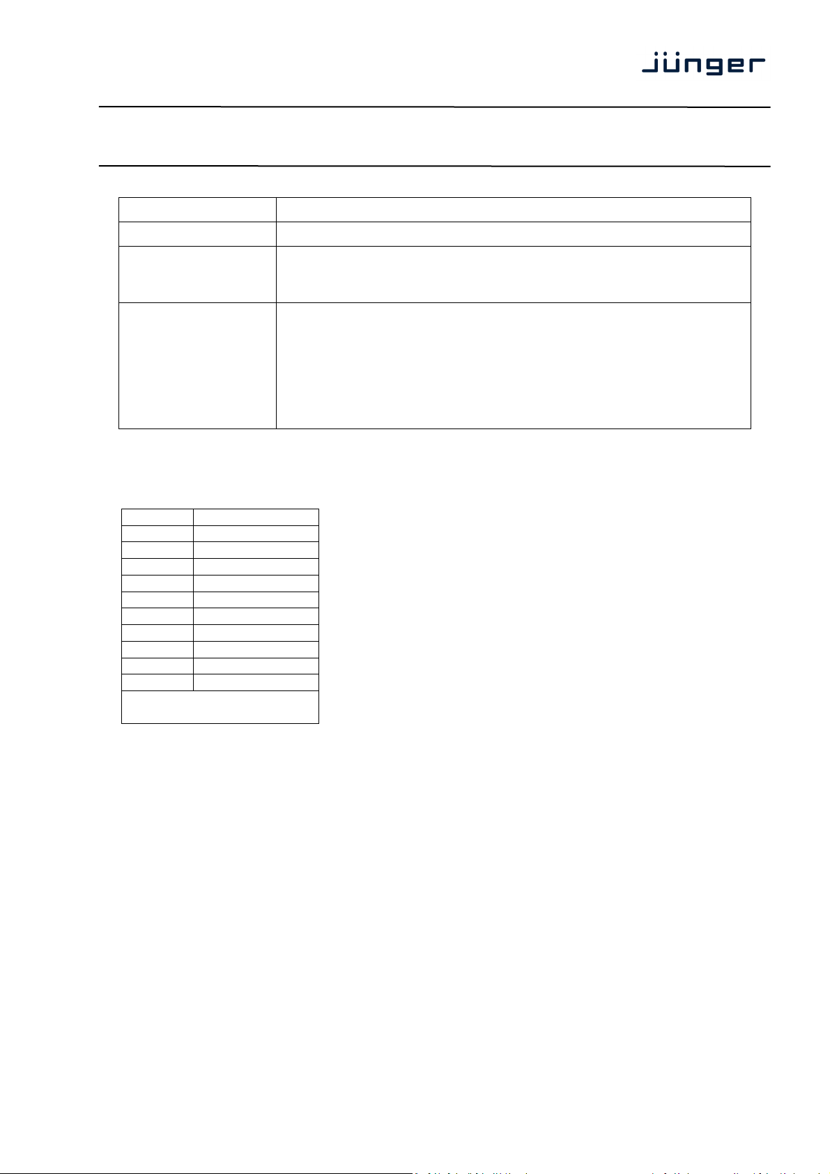
General Features
Metadata output pin assignment (D-Sub9 female):
• Decoding of compressed multichannel audio up to 7.1
• Decoder and encoder for Dolby® Pro Logic II coded / downmixed
audio
• Auxiliary delay path (stereo) to compensate decoder latency
• Metadata extraction from encoded audio
• Metadata generator to generate or alter Dolby® metadata
• Audio Description supported
C8621
Pin Function
1 GND
2 TX13 TX2+
4 GND
5
6 GND
7 TX1+
8 TX29 GND
Shell GND
(TX1 and TX2 carry the
same signal)
Page 3/
Page 4
19
digital audio
modular
processing system
Dolby® E / D / D plus decoder
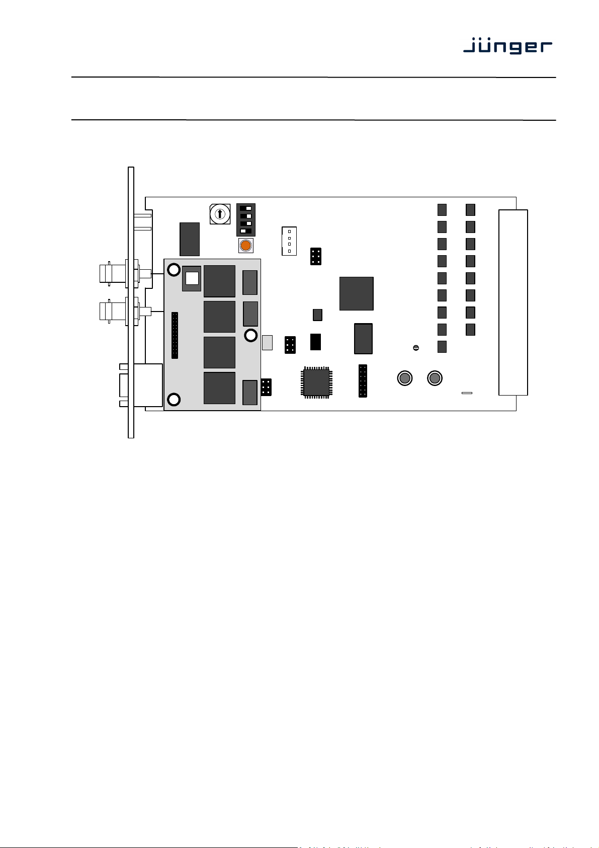
Installation:
ADDRESS
SW1
ON DIP
C8000
ID +16
1 2 3 4
BUS-EN
INIT
C8621
BDS
GND
BOOT
FAIL
Set the ADDRESS rotary encoder to an address, which is not in use by another module
of a C8000 frame (for details regarding CAN addressing, see C8k system manual).
BUS-EN = OFF will disable the bus driver circuits on power up
SW-1B = not used, must be OFF
SW-1C = not used, must be OFF
ID +16 = ON enables the CAN “+16” address scheme to handle up to 32 modules
Important Note! If the module has an unknown bus configuration, you must set BUS-EN=OFF, before
inserting the module into a C8000 frame. Otherwise you risk disturbing other channels of the frame.
When you press the INIT button during power up, it will initialize the module parameters to factory
default values.
Status LEDs:
On the front panel are 3 status LEDs:
STATUS green = OK
red = bad
flashing = module is in focus of the frame controller (under GUI control)
Decoding green = the decoder reads a proper Dolby encoded signal
off = no Dolby encoded signal is present
Page 4/
Page 5
19
digital audio
modular
C8000
processing system
Dolby® E / D / D plus decoder
Remote configuration via web interface:
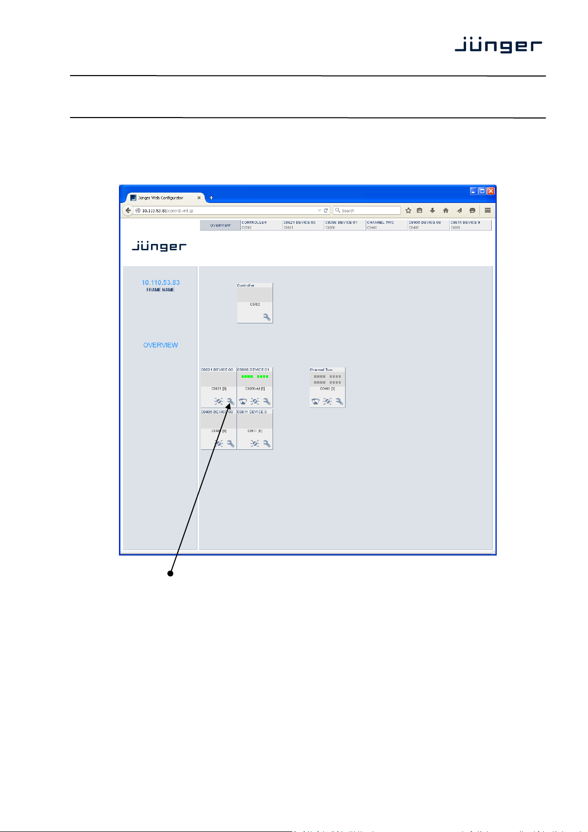
OVERVIEW:
C8621
Clicking on the spanner tool within the module graphics of the C8621 will open the pages of that
module.
Page 5/
Page 6
19
digital audio
modular
processing system
Dolby® E / D / D plus decoder
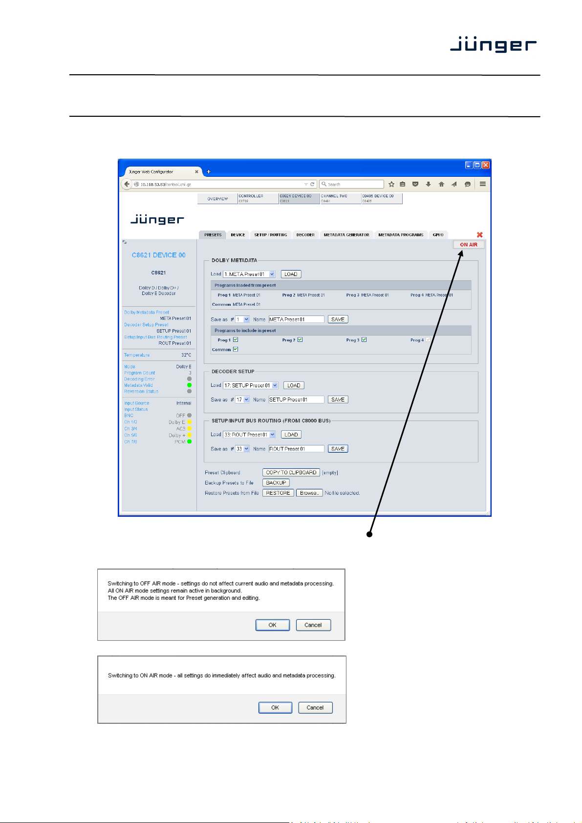
PRESETS
C8000
C8621
Important Note! The module may be controlled in ON AIR mode I.e. all settings have immediate affect.
While in OFF AIR mode you may prepare presets without affecting the current operation.
In this case online functions like preset clip board are not available.
If you hover with the mouse over
that switch in OFF AIR mode the hint:
"Processing is active, but settings are
offline" will be displayed.
This pop-up appeaers when you switch
back to ON AIR mode.
Page 6/
Page 7

19
digital audio
modular
C8000
processing system
Dolby® E / D / D plus decoder
DOLBY METADATA Since the C8621 also offers a metadata generator a bank of 16
Load [1: "name" … 16: "name"]
Select a preset by number/name and press <LOAD NOW>.
The preset number and name loaded will automatically appear in
Programs loaded [Prog 1 – preset name xy … Prog 4 – preset name xy / common]
from preset Shows the preset name and number [xy] from which the
Initially the preset names and numbers are empty, represented
Important Note! The metadata structure of the c8k system is defined for a maximum number of four
supported programs. I.e. the metadata generator will generate up to four independent sets of metadata
for a RDD6 compliant stream. If derived from the Dolby decoder the generator will enter the reversion
mode if the number of programs of the Dolby E stream received does not match this definition.
Save as # [1 … 16]
You must elect a preset memory number where you would like to
Name [16 character ASCII text]
Assign a name to the preset you are about to save here.
Programs to include Tick the check box(es) for which program this preset shall be
in preset saved and press <SAVE NOW>.
The number and the name appear automatically in the "Load"
DECODER SETUP Refers to the DECODE pane
Load [17: "name" … 32: "name"]
Select a preset by number/name and press <LOAD NOW>.
The preset number and name loaded will automatically appear in
Save as # [17 .. 32]
Select a preset memory number where you
Name [16 character ASCII text]
Assign a name to the preset you are about to save
SETUP/INPUT BUS ROUTING Refers to the SETUP / ROUTING pane
(FROM C8000 BUS) A bank of 8 presets to recall device settings.
Load [33: "name" … 40: "name"]
Select a preset by number/name and press <LOAD NOW>.
The preset number and name loaded will automatically appear in
Save as # [33 … 40]
Select a preset memory number where you would like to save
presets to recall Dolby metadata parameters is implemented.
the Save as # and Name field below.
respective program metadata or common ones (e.g. Dolby E
frame rate, program configuration etc) have been loaded.
by a dash.
save the actual metadata parameters.
fields as well because they are active now.
the Save as # and Name field below.
would like to save the actual audio program parameters.
(up to 16 digits) and press <SAVE NOW>.
the Save as # and Name field below.
the actual audio program parameters.
C8621
Page 7/
Page 8

19
digital audio
modular
processing system
Dolby® E / D / D plus decoder
Name [16 character ASCII text]
Assign a name to the preset you are about to save
Preset Clipboard Copy the active presets to a clipboard, the data may be used by
Backup Presets to File Creates a backup XML file which may be stored to the PC.
Restore Presets from File You can <browse> for a backup file from the PC and restore it
STATUS DISPLAY
C8000
C8621
(up to 16 digits) and press <SAVE NOW>.
other modules inside the same frame.
by pressing the <RESTORE> soft button.
If you are controlling a specific module you will see a status frame on the
left hand side that also appears if you hover with the mouse over the
graphical boxes in the GUIs OVERVIEW display. If the GUI size does not
fit your screen well you may decrease the size of the status display by
clicking on the little arrows in the upper left corner to get a smaller view.
Dolby Metadata Preset Name of the actual preset loaded
Decoder Setup Preset Name of the actual preset loaded
Setup/Input Bus Routing Preset Name of the actual preset loaded
The word "modified" appears as a
prefix if a parameter has been
Temperature Temperature of the module PCB
Mode [Dolby E / Dolby Digital / Digital +]
Program Count [1 … 8]
Decoding Error [grey / red]
Metadata Valid [green / red]
Reversion Status [grey / red]
Input Source [External BNC / Internal]
Input Status Signal status of the respective input
BNC [OFF (grey)
PCM (green)
AC3 / Dolby + / Dolby E (yellow)
ERROR (red)]
Ch 1/2 Similar to BNC
Ch 3/4 Similar to BNC
Ch 5/6 Similar to BNC
Ch 7/8 Similar to BNC
changed by the operator
Page 8/
Page 9

19
digital audio
modular
processing system
Dolby® E / D / D plus decoder
DEVICE
C8000
C8621
INFO
Device Name [16 digit ASCII text]
Pressing <CHANGE NAME> will do so.
Platform [C8621]
Hardware related descriptor.
Parameter Version [x]
Software related descriptor (feature set).
FIRMWARE
Controller [xy]
Actual version of the module controller firmware.
Metadata Controller [xy]
Actual version of the metadata subsystem.
FPGA [xy]
Actual version of the system FPGA.
Page 9/
Page 10

19
digital audio
modular
C8000
processing system
Dolby® E / D / D plus decoder
Dolby Decoder [e.g. 1.6.0.7]
Actual firmware version of the Dolby OEM board CAT1100.
Important Note! The firmware of the Dolby OEM board CAT1100 can be updated via the
frame controller: C8702 > SOFTWARE UPDATE > MODULES FIRMWARE SINGLE UPDATE:
The process of uploading the firmware from the PC via the frame controller will take approx. 20mins.
The GUI can not display the progress. It just polls the frame controller to find out if the upload has
finished. If you want to see some progress you may connect a terminal program to the serial port of the
frame controller (see C8702 manual for details) and observe the acknowledge dots of the flash
programming of the module.
It is a two tier process. After the upload is finished you must go to this DEVICE page and start the
update of the CAT1100 from here by pressing the <UPDATE> button:
C8621
You will get a progress display:
And a success message (or not if it fails):
This process will take approx. 2mins. Afterwards the module will automatically restart.
RESET
Restart Module <RESTART>
Pressing the soft button will warm start the module
Initialize and Restore <INITIALIZE>
Factory Defaults Pressing the soft button, will clear the parameter memory and
will initialize all parameters to their factory default values.
BACKUP / RESTORE
Backup Settings and <BACKUP>
Presets to File Pressing the soft button will create an XML file that one may
store on a PC.
Restore Settings and <RESTORE> l
Presets from File Pressing the soft button will upload a backup file that has been
selected via soft button <BROWSE> and move the previously
4stored settings back to the module.
Page 10/
Page 11

19
digital audio
modular
C8000
processing system
Dolby® E / D / D plus decoder
SETUP/ROUTING: Setup of the module and the audio bus routing
C8621
BNC Input You may connect an AES signal to the BNC front panel connector that
carries an encoded Dolby stream.
From C8000 System Bus
8 Ch Mux [S1 … S32]
Selection of a backplane bus that carries an eight channel multiplex.
The check boxes select which pair from the multiplex stream will feed the
respective input(s) of the DECODER.
Ch 1/2 … Ch 7/8 [S1 … S32]
Here you may select the inputs of the decoder. The radio button on the
first input selects between this bus selector and the front panel BNC
connector. An extra delay is provided for a 2Ch PCM signal. The delay
can be used to match the Dolby decoding latency for a stereo program.
It may also be used to delay subset metadata from the decoder output
(subset metadata are automatically attached to all PCM audio outputs
from Ch 1/2 to Ch 9/10 of the module).
Page 11/
Page 12

19
digital audio
modular
C8000
processing system
Dolby® E / D / D plus decoder
Decoder [Dolby E / Dolby D / Dolby Digital + / PCM / n.a.]
Within the Decoder box you will see the format of the incoming stream.
In case of Dolby E, the number of programs and the respective program
configuration (e.g. 5.1 + 2) are shown.
In case of AC3 or Digital plus you will get the channel mode of the
encoded program (e.g. 3/2L).
The example above shows a Dolby E stream containing 2 programs
(5.1 + 2).
Important Note: If the input format of the decoder is PCM, such signal will automatically be sent
to the first output pair (Ch1/2), AKA "PCM pass through".
Downmix [Auto / Lt/Rt / Lo/Ro / Pro Locic II (cons)]
Display of the downmix mode
DELAY An independent two channel delay block.
Coarse [0 … 335] ms
Fine [0 … 240] samples
Important Note! The output 7/8 of the decoder or the output of the delay can be selected as Ch 7/8
for the 8ch Mux (multiplex) mode.
BNC Output Downmix output from the Dolby OEM board.
To C8000 Bus The outputs from the decoder can be assigned to the C8k audio busses.
8ch Mux You can send the 8 channels from the decoder in 8ch multiplex mode
Enable Bus Driver [OFF / ON]
You can disable the output drivers by un-checking the Enable Bus Driver
Important Note! The bluish labels on the bus selectors represent the signal configuration of the decoder
output lines. This depends on the actual program configuration of the decoded stream. Downstream
equipment must be configured to receive the correct audio channels.
Bus Error Detection [ON / OFF]
BNC Error Detection The serial audio data from the frame bus can be monitored for proper
via one audio bus line. Ch 1/2 to Ch 7/8 are multiplexed that way.
check box.
positioning of an Error-Flag. A bad Error-Flag is an indication that
there is disturbance upstream (input signal, input module). The BNC
input is monitored for the AES status.
The Error Detection can be turned off and on in general or per input.
You will see the status on the left hand side: “Input Status”.
A grey “LED” shows that the detection is disabled. While green is OK,
red indicates an error condition.
The bus status as well as the external input (BNC) status may be
presented to external monitoring systems via SNMP. The frame controller
summarizes such status information and generates SNMP traps for the
frame as an entity or may activate GPOs (if a GPI/O module is installed).
The SNMP manager may afterwards poll the “modulesStatus” for more
detailed status information per input
(see SNMP documentation for details).
C8621
Page 12/
Page 13

19
digital audio
modular
C8000
processing system
Dolby® E / D / D plus decoder
SNMP: Metadata Error [OFF / ON]
The metadata error is part of the module status information presented via
SNMP. To avoid unnecessary alarms you may disable this function in
case the module is temporarily not in use.
DECODER: display of general decoder parameters and setup of decoder functions:
C8621
Decoder Depending on the actual input signal you will first see general
Bitstream Format [Dolby E 16Bit / Dolby E 20 Bit / Dolby Digital / Dolby Digital +]
Shows the format of the decoded Dolby bit stream.
Bit Stream Data Rate [e.g. 240]
(kbps) In case of a decoded consumer format
Decoder Status [OK / Fail]
information of the signal format received.
Page 13/
Page 14

19
digital audio
modular
C8000
processing system
Dolby® E / D / D plus decoder
Program Configuration [5.1 / 5.1 + 2 / 4x2 etc]
In case of Dolby E
Channel Mode [e.g. 3/2L]
In case of a consumer format
Dolby E Frame Rate [25 / 29,97 / 30 fps]
Dolby D+ Decoding [Main Only / Mixed Main & AD / AD Only]
Here you can tell the decoder which signal shall be appear at the
Downmix Output Format [Auto / Lt/Rt / Lo/Ro / Pro Logic II (cons)]
General switch for the 2 Ch downmix output
Decoding and DRC The decoder may also be used to apply the metadata to the
Dolby D/D+ Main [Bypass DRC & Dialnorm / Apply Dialnorm Only / Line Mode /
RF Mode / Mute Dolby D/D+]
Dolby D/D+ Downmix [Line Mode / RF Mode]
Dolby E Main [Bypass DRC & Dialnorm / Mute Dolby E]
Dolby E Downmix (Progr 1) [Line Mode / RF Mode]
PCM Main [Bypass DRC & Dialnorm / Mute PCM]
For special applications where PCM and Dolby E are altering at the
PCM Downmix (Prog 1) [Line Mode / RF Mode]
PCM Latency [Matched / Minimum]
If you frequently change between baseband PCM and decoded
Pro Logic II Decoding
Enable [OFF / ON]
Decoder Mode [Movie / Pro Logic Emulation]
Important Note! If a ProLogic encoded signal is received over a Dolby Digital or Dolby Digital plus
stream, the Channel Mode must be 2/0. Otherwise the ProLogic decoder will reject the signal.
The Dolby metadata system is too complex to describe in detail in a product manual such as this.
If you are not familiar with it, we recommend you study the many publications from Dolby Inc.
Especially the Dolby Metadata Guide is essential for understanding the parameters.
For details please visit the Dolby web site:
http://www.dolby.com/gb/en/professional/technology/landing.html
We cannot guarantee that the link is active forever so you may browse other Dolby resources as well.
Specifically concerning metadata we also recommend the SMPTE document RDD6-2008.
output of the decoder.
decoded PCM signals. In this case it may act as a STB.
decoder input, you can mute PCM to avoid remainders of Dolby E
data packets appearing at the decoder output.
E.g. when playing a tape from shuttle or stop to play.
signal it my be good idea if both paths have the same latency.
C8621
Page 14/
Page 15

19
digital audio
modular
processing system
Dolby® E / D / D plus decoder
METADATA GENERATOR
C8000
C8621
The C8621 provides an extra metadata generator that can be used transparent (decoded metadata
appear at the outputs) or controlled via the setup data. In the latter case the output metadata may be
derived selectively from the input (the decoder).
D.SUB Output The output of the metadata generator is available at the D-Sub
To C8000 System Bus Metadata will be automatically attached to the bus outputs except
Metadata A specific bus can be used to move metadata alongside the back
connector in asynchronous RDD6 format.
for channels Ch 11/12 and 7/8 if it is derived from the delay output
so one may use the delay for metadata delay as well.
plane in asynchronous RDD6 format like at the D-Sub output.
Page 15/
Page 16

19
digital audio
modular
C8000
processing system
Dolby® E / D / D plus decoder
Metadata Generator
Generator Mode [Transparent / Setup Mode]
Generator Program Config [5.1+2 / 4x2 / 5.1 / 3x2 / Follow Input]
Current Program Config [5.1+2 / 4x2 / 5.1 etc]
Generator Sync Source [Bus/Vsync / Audio (25 / 29.97 / 30fps)]
Current Frame Rate [25 / 29,97 / 30fps]
Reversion In case of an input failure or a mismatch between input program
configuration and the possible system program configurations, the
Metadata Reversion Status [Inactive / Reversion]
Metadata Reversion Mode [Preset / Last Valid]
The generator can either continue using previous metadata or
Reversion Preset [Metadata Preset x]
A pre-defined preset that will be automatically recalled if the
generator may enter the reversion mode.
it will use the metadata from a preset
generator enters the reversion mode.
C8621
Page 16/
Page 17

19
digital audio
modular
C8000
processing system
Dolby® E / D / D plus decoder
METADATA PROGRAMS: Display of program-specific Metadata
These Input values are for display only, that’s why the fields are grey and the content can not be
changed. The Follow Input check boxes determine if metadata are used from the decoder or from a
preset.
The example below shows the metadata of the first program of a Dolby E stream that must be
encoded to transmit two programs 5.1 +2 (surround and stereo).
C8621
At the input side we decode a Dolby E stream that is encoded for a 5.1 program.
As per definition the Junger Dolby implementation supports only the program configurations:
5.1 / 3x2 / 5.1+2 / 4x2 so a maximum of 4 tab sheets will contain Output metadata. The other tabs are
for the display of incoming metadata only (if the number of programs is higher than the generator
set-up. In this example case we have two program tabs Prog 1 and Prog 2 because the generator is
set for 5.1+2 and the input has only one program.
Page 17/
Page 18

19
digital audio
modular
processing system
Dolby® E / D / D plus decoder
GPI/O
C8000
C8621
GPIs are useful if you want to recall settings (e.g. by loading presets) or turn functions on or off
remotely. A C8k frame can handle 127 independent virtual GPI numbers. You must assign a unique
number to the respective preset / function. Such numbers are generated by the brc8x Broadcast
Remote Controller or by the C8817 GPI/O interface module. If the C8621 receives such a number
via the CAN bus, it will load the respective preset.
Page 18/
Page 19

19
digital audio
modular
C8000
processing system
Dolby® E / D / D plus decoder
GPOs are meant to present status information to external devices. A C8k frame can handle 127
independent virtual GPO numbers. You must assign a unique number to the respective
preset / function. In case a preset is loaded either manually via the GUI or remotely via the
brc8x or via a GPI/O module, the assigned number will be broadcast over the CAN bus.
A GPI/O module which has that number assigned to a physical output will engage that relay or a
brc8x may turn on an assigned button tally light.
C8621
Clear GPO on If a GPO indicates that a certain preset is loaded and if you
Preset modified change parameters which are related to that preset the word
"modified" will be displayed in line with the preset name in the
status window.
In this case you may clear that GPO to indicate that the
parameters are not the same as the content of the previously
loaded preset.
Important Note! GPOs from modules and GPIs to modules don't "see" each other.
I.e. you can't use a status GPO of module A to load a preset for module B by simply assigning
a GPO number of module A as a GPI number of module B. If this is a requirement you
must involve the GPI/O logic function of the C8817 GPI/O module (see manual for details) to convert
system GPOs into system GPIs.
Page 19/
 Loading...