

Page 1
digital audio
modular
processing system
C8000
Dolby® E encoder
features
• Dolby® E compliant Encoder
• 8 channels (up to eight programs)
• Audio input up to 24Bit, 48kHz
• 16 / 20Bit audio data format
• RS485 Metadata input
• Unique Metadata extractor to read Metadata inserted into PCM audio User Bits
• Metadata from C8000 internal audio bus, external RS485 input or presets
• Eight Metadata presets
• Dolby® Metadata display and editing
• Encoded output stream available on C8000 internal audio bus
• Encoded output stream available on unbalanced AES output
• Remote control (web interface) via C8702 frame controller
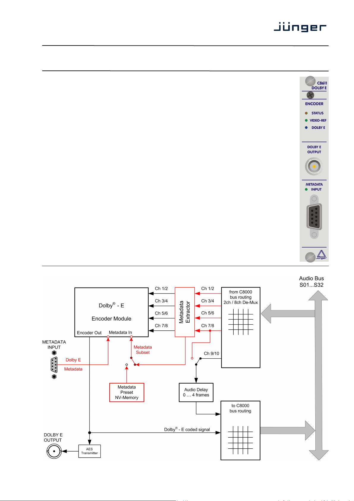
block diagram
C8611
1/13
Page 2

digital audio
modular
processing system
C8000
Dolby® E encoder
technical specifications
External output:
connector BNC
impedance 75Ω
signal level 1Vpp
standard AES 3, SMPTE 276M unbalanced
data format 16, 20bit
sample rate 48kHz
Output audio formats:
Dolby® E 16, 20bit streams, 48kHz Sample Rate
Latency: 1 video frame
Metadata input:
format Standard Dolby® Metadata stream (RS485)
baud rate 115,2kbps
connector Sub-D, 9-pin, female
pin assignment
Backplane connector: ref. to DIN 41612, 64pin, a+b, male
Power supply: +5V DC
Consumption: approx. 600mA
Dimensions: 3RU, 4HP, 160mmd deep (Euro Format)
Ambient: 10ºC to 40ºC
Humidity: 90%, non condensing
connector : Metadata INPUT
female 9-pin D-Sub
1 GND
2
3 Rx (+)
4 GND
5
6 GND
7
8 Rx (-)
9 GND
C8611
2/13
Page 3
digital audio
modular
processing system
installation
C8000
Dolby® E encoder
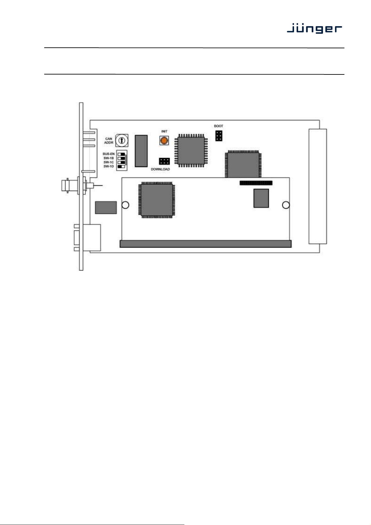
C8611
Set the CAN ADDR rotary encoder to an address, which is not in use by another module
of a C8000 frame (for details regarding CAN addressing, see C8000 system manual).
BUS-EN = OFF will disable the bus driver circuits on power up
SW-1B = ON enables the CAN “+16” address schema to handle up to 32 modules
SW-1C = not used
SW-1D = not used
Important Note! If the module has an unknown bus configuration, you must set BUS-EN=OFF, before
inserting the module into a C8000 frame. Otherwise you risk disturbing other channels of the frame.
Pressing the INIT button during power up will initialize the module parameters to factory default values.
status LEDs
STATUS green = OK
red = bad
flashing
green = under GUI control
VIDEO-REF green = frame rate matches the one selected for Dolby E encoding
Off = no Frame Reference available or frame rate of the reference
DOLBY E blue = the encoder delivers a proper Dolby E signal
Off = Dolby E encoding error (see VIDEO-REF)
does not match the one selected for Dolby E encoding
3/13
Page 4
digital audio
modular
processing system
C8000
Dolby® E encoder
web browser based configuration
Set up of all configurations, parameters and functions via a web browser.
See also C8702 Frame Controller manual.
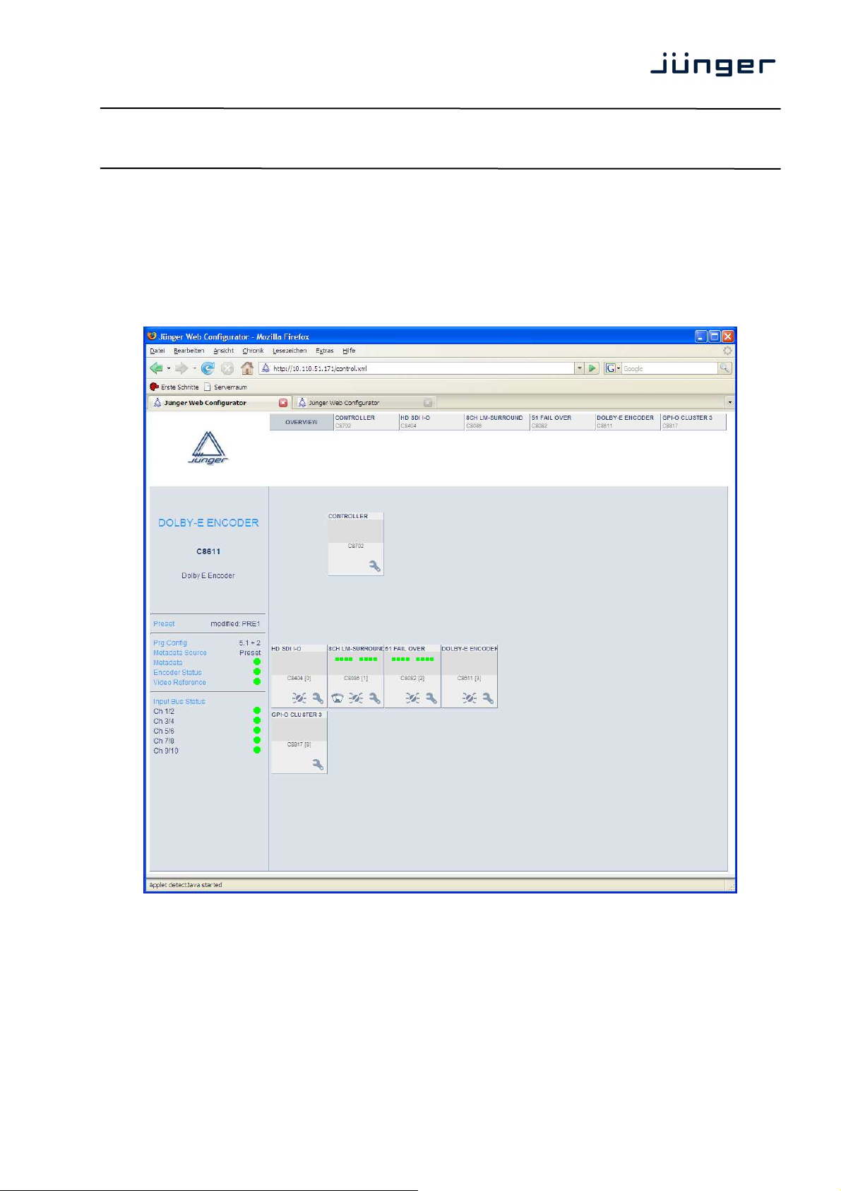
OVERVIEW
C8611
The above example shows a C8611 (Name: “DOLBY E ENCODER”) in a typical processing chain.
Clicking on the spanner tool within the module graphics of the C8611 will open the pages of that
module.
If you click on the switch tool you will get the page for changing Presets only.
4/13
Page 5

digital audio
modular
processing system
PRESETS
C8000
Dolby® E encoder
C8611
Metadata the module provides 16 Metadata presets which may be used when the
Metadata source is set to Preset. The settings found on the DOLBY E
and PROG. METADATA pages are stored in Presets.
If the Metadata Source is set to "Bus". Each parameter may be
overwritten independently on the respective pages. In this case the preset
Input Bus Routing the modules provides 8 preset which may be used to set up the routing of
Load Preset will load one of the 8 available Presets from the modules NV memory.
Save as Preset here you can select a Preset Number (memory location) and
will keep these values.
the input busses (e.g. to select different audio inputs from the system.
assign that preset a 16 character name.
5/13
Page 6

digital audio
modular
processing system
C8000
Dolby® E encoder
C8611
Preset Clipboard you can copy the data of the active parameters of the two sets of Presets
to a clip board and paste such data into the Preset memory of another
Backup Presets store all presets of one C8611 into a file.
Restore Presets restore all presets of a C8611 from a file.
DEVICE
module within one frame.
Device Name You can assign a 16 digit name to the module.
Restart Module Pressing <RESTART> will warm start the module.
Initialize Pressing <INITIALIZE> will initialize the module to factory default.
Controller Version Display of the firmware version of the module controller.
Dolby Firmware Version Version of the Dolby piggyback module.
6/13
Page 7

digital audio
modular
processing system
C8000
Dolby® E encoder
C8611
BACKUP Pressing <BACKUP> will move all settings including the Presets to the
RESTORE Pressing <RESTORE> after loading a backup file will move all settings
SETUP / ROUTING : setup of the module and the Bus routing
PC, so you can store the backup data to a file.
including the Presets back to the module.
From C8000 Bus The audio busses from the C8k frame must be assigned to the encoder
for the respective signals. The labels at the encoder input show which
signals the encoder expects due to its configuration determined by
Program Config (see DOLBY E page). If some of the 8 input signals are
multiplexed in 8ch mode, you must check the respective channel check
boxes (see example above). This is the so called MixMux mode where
8ch Mux here one must select the bus that is fed in 8 channel Mux mode from an
the module may be fed from a combination of 2Ch and 8Ch signals.
upstream module. The check boxes below determine which channel pair
will be taken from the 8 channel Mux.
7/13
Page 8

digital audio
modular
processing system
C8000
Dolby® E encoder
C8611
Metadata The Metadata maybe inserted in the USER bits of the PCM signal(s) on
the C8k audio busses. Here you can select from which bus it should be
PCM An independent digital stereo (or 2Ch) audio signal (PCM or encoded)
Delay The module provides a 2ch delay (up to 4 frames) to compensate for the
To C8000 System Bus The encoder output may be assigned to the C8k busses. It is fed to the
Enable Bus Driver You may turn off (tri state mode) all bus drivers for installation to prevent
External Output BNC The Dolby E encoded bit stream is sent out via an unbalanced AES3
Metadata Source Preset :
The parameters to setup the Dolby E encoder and the program
Bus :
The Metadata for the Dolby E encoder are extracted from the USER
external (RS485) :
The Metadata for the Dolby E encoder are received by the 9-pin Sub D
Error Detection The serial audio data from the frame bus can be monitored for proper
Metadata Reversion Last used :
Mode If a Metadata error is detected from the source, the encoding process will
Stop encoding :
The encoder will stop encoding in case of a Metadata error from the input
read.
may be taken from the c8k bus to compensate for the Dolby E encoding
delay.
Dolby E encoding delay.
external BNC output as well.
conflicts with modules already in service.
output in parallel to the C8k audio bus
Metadata are defined manually. You may also load a Preset edit these
parameters and store them as a Preset again.
bits in Metadata Subset format of one of the incoming PCM signals
connector at the front side of the module in Dolby E format.
positioning of an Error-Flag. A bad Error-Flag is an indication that
there is disturbance upstream (input signal, input module,
DSP module).
The Error Detection can be turned Off and On for each input from the
bus. You will see the status on the left hand side: “Input Bus Status”.
A grey “LED” shows that the detection is disabled. While green is OK,
red indicates an error condition.
The bus status may be presented to external monitoring systems via
SNMP. The frame controller summarizes such status information and
generates SNMP traps for the frame as an entity or may activate GPOs
(if GPI/O module(s) are installed). The SNMP manager may afterwards
poll the “modulesStatus” for more detailed status information per input
(see SNMP documentation for details).
continue with “last used” parameters
8/13
Page 9

digital audio
modular
processing system
C8000
Dolby® E encoder
C8611
Dolby® Metadata
The Dolby® Laboratories, Inc. have introduced the “data about the audio data“, the Dolby® Metadata
which travel along with the multi channel bit stream from acquisition (point of audio recording) to delivery
(Dolby Digital decoder at home either as part of the TV Set Top Box or the home theater system). Dolby®
Metadata in the end of the day may control the home equipment in a way that the sound impression is as
close as possible to what the producers intention was when mixing a movie sound track.
There is not enough room for explanation of the Dolby Metadata system in a product manual like this.
We recommend to those who are not familiar with this quite complex matter, to study the many
publications from Dolby Inc. probably found here:
http://www.dolby.com/technicallibrary.aspx?id=306
You can browse the Technical Library and <Search> for “Dolby E”. Here you will find the “Dolby®
Metadata Guide”.
9/13
Page 10

digital audio
modular
processing system
C8000
Dolby® E encoder
DOLBY E : setup of the Dolby E related Metadata
C8611
The Dolby E parameters contain the information of the Dolby E stream. The table below shows the
parameters and their possible values :
Parameter
5.1+2, 5.1 +2x1, 4+4, 4+2x2, 4+2+2x1, 4+4x1
4x2, 3x2+2x1, 2x2+4x1, 2+6x1, 8x1
Program Configuration
Bitstream Format Dolby E 16Bit, Dolby E 20Bit
Frame Rate None, 23,98Hz, 24Hz, 25Hz (PAL)
Latency Reduction
(Dolby E alignment)
Program Description Text 32-character text coded program
5.1, 4+2, 4+2x1, 3x2, 2x2+2x1, 2+4x1, 6x1
4, 2+2, 2+2x1, 4x1
7.1, 7.1SCRN
29,97Hz (NTSC), 30Hz, 50Hz, 59,94Hz, 60Hz
0 … 32 Samples (moves the beginning of the Dolby E
frame towards the start of the video frame
Range
10/13
Page 11

digital audio
modular
processing system
C8000
Dolby® E encoder
PROG. METADATA : Setup of Dolby Digital Metadata
example below shows 2 programs (5.1 & stereo) :
C8611
The PROG.METADATA are used to set up the Dolby D encoder and control the Dolby D decoder
at home.
A lot of these Metadata are applicable only for surround programs.
The table on the next page is an example for 2 programs. The possible Data Rate depends on the
Channel Mode (some channel modes require a minimum Data Rate).
11/13
Page 12

digital audio
modular
processing system
Data Rate (kbps)
Channel Mode
LFE On, Off N.A.
Bit Stream Mode
Original Bit Stream
Copyright
Dynamic Range Control
Dialog Normalization -1dBFS ... -31dBFS -1dBFS ... -31dBFS
Profile Line Mode
Profile RF Mode
DC-Highpass On, Off On, Off
Low Pass On, Off On, Off
LFE Low Pass On, Off N.A.
RF Overmod. Protection On, Off On, Off
Surround 3dB Attenuation On, Off N.A.
Surround Phase Shift On, Off N.A
Nominal Center Mix Level -3dB, -4,5dB, -6dB N.A
Nominal Surround Mix Level -3dB, -6dB, OFF N.A
Preferred Downmix Mode Not indicated
Lo/Ro Center Mix Level OFF, -6dB, -4,5dB
Lo/Ro Surround Mix Level OFF, -6dB, -4,5dB
Lt/Rt Center Mix Level OFF, -6dB, -4,5dB
Lt/Rt Surround Mix Level OFF, -6dB, -4,5dB
Dolby® E encoder
Parameter
General
Filter
Downmix
C8000
C8611
Range - Program 1 Range - Program 2
32, 40, 48, 56, 64,
80, 96, 112, 128,
160, 192, 224, 256,
320, 384, 448, 512,
576, 640,
unspecified.
1+1, 1/0, 2/0, 3/0,
2/1, 3/1, 2/2, 3/2
C. Main, Mus Eff
Vis. Imp, H. Imp
Dialogue, Comment
Emerg., Karaoke
On, Off On, Off
On, Off
None, Film St
Film Lt, Mus St
Mus Lt, Speech
None, Film St
Film Lt, Mus St
Mus Lt, Speech
Lt/Rt, Lo/Ro
-3dB, -1,5dB, 0dB
1,5dB, 3dB
-3dB, -1,5dB, 0dB
1,5dB, 3dB
-3dB, -1,5dB, 0dB
1,5dB, 3dB
-3dB, -1,5dB, 0dB
1,5dB, 3dB
32, 40, 48, 56, 64, 80,
96, 112, 128, 160,
192, 224, 256, 320,
384, 448, 512, 576,
640, unspecified.
1+1, 1/0, 2/0
C. Main, Mus Eff
Vis. Imp, H. Imp
Dialogue, Comment
Emerg., Karaoke
On, Off
None, Film St
Film Lt, Mus St
Mus Lt, Speech
None, Film St
Film Lt, Mus St
Mus Lt, Speech
N.A
N.A
N.A
N.A
N.A
12/13
Page 13

digital audio
modular
processing system
C8000
Dolby® E encoder
GPI/O setup of the GPI/Os
C8611
You can assign GPI numbers to activate one of the various Presets.
If a GPI is detected by a GPI/O module of the C8k system, it puts an associated number on the CAN
bus. Each module in a frame permanently listens for such numbers and will perform the
pre-programmed action if it reads that number.
You can assign GPO numbers which will indicate the respective action.
E.g. if an Encoding Error occurs the C8611 puts the associated GPO number on the CAN bus. The
GPI/O module permanently listens for such numbers. If it reads such number it will engage the
respective GPO (see C8817 manual for details).
13/13
 Loading...