

Page 1
digital audio
modular
processing system
C8000
Dolby® E / D / D plus decoder
features
• Dolby® E, D, D plus decoder
• RS 485 RDDD-6 metadata output
• Unbalanced, asynchronous AES input for Dolby® E , D, D plus encoded signals
• 16 / 20 / 24 Bit audio data format
• Automatic format detection (Dolby® E, D, D plus, PCM)
• Automatic PCM pass through to Ch1/2 output
• Unique Dolby® metadata transport (inserter into the AES USER Bit)
• 2Ch Delay for PCM audio and / or metadata
• Program monitoring (down mix to mono, Lo/Ro, Lt/Rt)
• Program specific metadata display
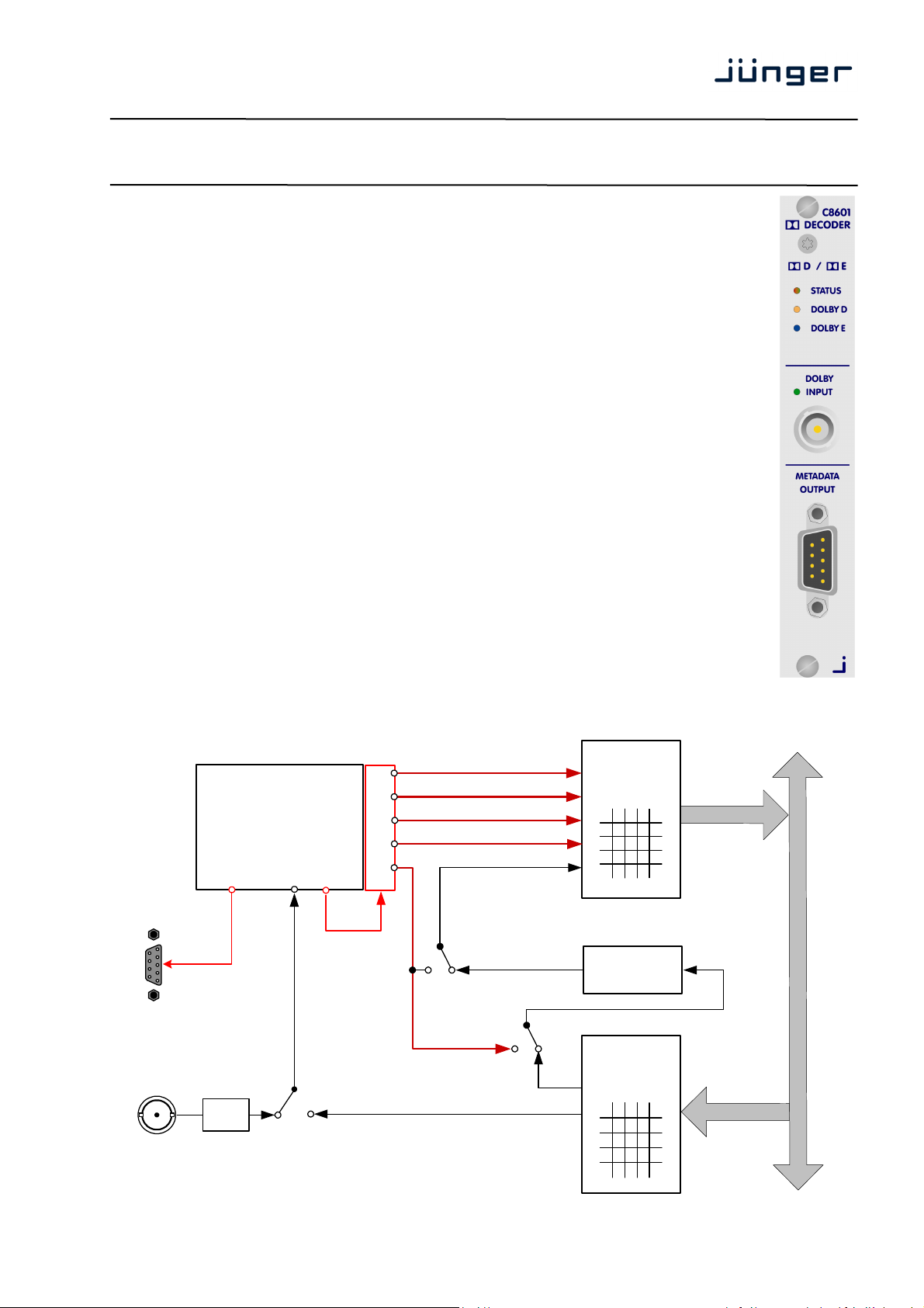
block diagram
C8601
Metadata
Output
RS485
Dolby
Input
Dolby® E
Metadata
Receiver
Dolby® E / D / D+
Decoder Module
EXT / INT
AES
Subset
Metadata
Audio Bus
Metadata Inserter
Monitor
Ch 1/2
Ch 3/4
Ch 5/6
Ch 7/8
DLY
INT
to C8000
bus routing
2ch / 8ch Mux
Audio Delay
0 … 32 frames
from C8000
bus routing
2ch
S01...S32
C8601_manual_EN_150324.doc
Page 2

digital audio
11
modular
processing system
C8000
Dolby® E / D / D plus decoder
technical specifications
External input:
connector BNC
impedance 75Ω
signal level 0,1 … 2,5Vpp
standard AES 3, SMPTE 276M unbalanced
data format 16, 20, 24bit
sample rate 32 … 48kHz
Input audio formats:
Dolby E 16, 20, 24bit streams
48kHz
Dolby Digital 16 or 32bit streams
32 …. 48kHz
Latency:
Dolby E 1 video frame
Dolby Digital 32msec
PCM < 10msec
Video synchronization: external synchronization possible via C8830 (PAL, NTSC, HD)
Metadata output:
format Standard Dolby® Metadata stream (SMPTE RDD 6-2008)
baud rate 115,2kbps
connector Sub-D, 9-pin, male
pin assignment
Backplane connector: ref. to DIN 41612, 64pin, a+b, male
Power supply: +5V DC
Consumption: approx. 500mA
Dimensions: 3RU, 4HP, 160mmd deep (Euro Format)
Ambient: 10ºC to 40ºC
Humidity: 90%, non condensing
if Dolby E decoding must be frame accurate
connector : Metadata OUTPUT
male 9-pin D-Sub
1 GND
2
3 Tx (+)
4 GND
5
6 GND
7
8 Tx (-)
9 GND
C8601
Page 2/
Page 3
digital audio
11
modular
processing system
C8000
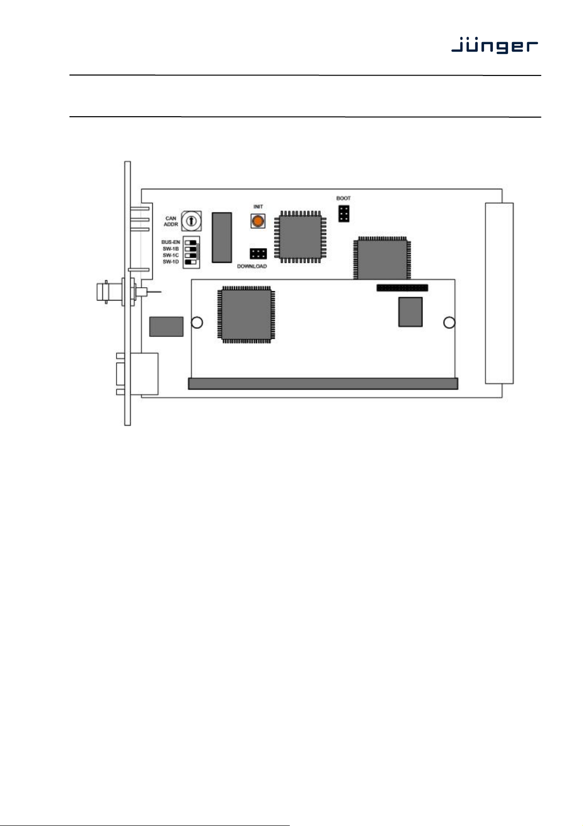
Installation
Dolby® E / D / D plus decoder
C8601
Set the CAN ADDR rotary encoder to an address which is not in use by another module
of a C8000 frame (for details regarding CAN addressing, see C8k system manual).
BUS-EN = OFF will disable the bus driver circuits on power up
SW-1B = ON enables the CAN “+16” address scheme to handle up to 32 modules
SW-1C = not used
SW-1D = not used
Important Note! If the module has an unknown bus configuration, you must set BUS-EN=OFF,
before inserting the module into a C8000 frame. Otherwise you risk to disturbing other
channels of the frame.
When you press the INIT button during power up, it will initialize the module parameters to factory
default values.
status LEDs
On the front panel are 3 status LEDs:
STATUS green = OK
red = bad
flashing = module is in focus of the frame controller (under GUI control)
DOLBY D green = the decoder reads a proper Dolby D / D plus signal
Off = Dolby D decoding error (no Dolby D / D plus signal)
DOLBY E green = the decoder reads a proper Dolby E signal
Off = Dolby E decoding error (no Dolby E signal)
Page 3/
Page 4
digital audio
11
modular
processing system
C8000
Dolby® E / D / D plus decoder
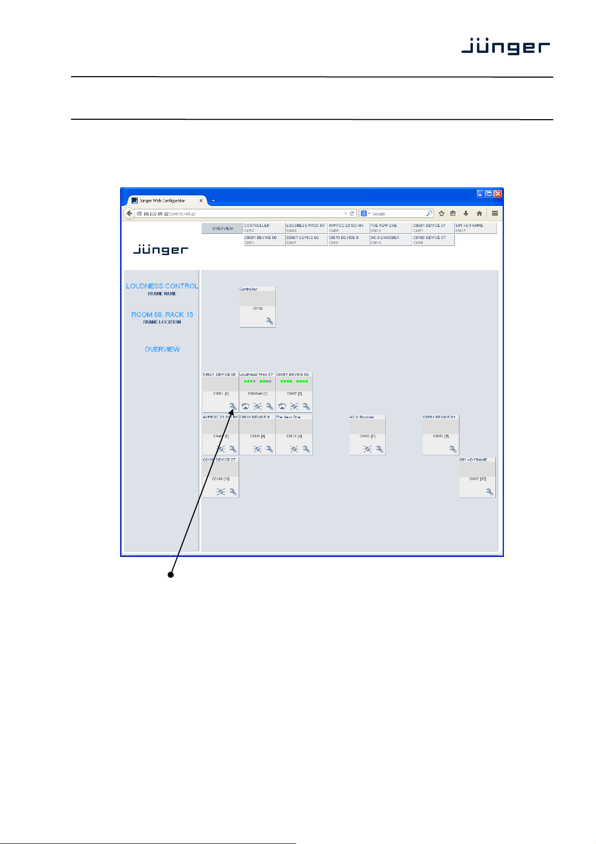
remote configuration via web interface
OVERVIEW :
C8601
Clicking on the spanner tool within the module graphics of the C8601 will open the pages of that
module.
Page 4/
Page 5

digital audio
11
modular
processing system
C8000
DEVICE
Dolby® E / D / D plus decoder
C8601
INFO
Device Name You may assign a 16 digit name to the module.
Platform [c8601]
Hardware related descriptor
Parameter Version [2]
Software related descriptor (represents the feature set)
FIRMWARE
Controller [50]
Installed version of the module controller
Dolby Firmware Version [e.g. 2..1.3.0]
Version of the Dolby OEM board firmware
Page 5/
Page 6

digital audio
11
modular
processing system
C8000
Dolby® E / D / D plus decoder
RESET
Restart Module <RESTART>
Pressing the soft button will warm start the module
Initialize and Restore <INITIALIZE>
Factory Defaults Pressing the soft button, will clear the parameter memory and
will initialize all parameters to their factory default values.
BACKUP / RESTORE
Backup Settings and <BACKUP>
Presets to File Pressing the soft button will create an XML file that one may
Restore Settings and <RESTORE> l
Presets from File Pressing the soft button will upload a backup file that has been
SETUP/ROUTING : setup of the module and the audio bus routing
store on a PC.
selected via soft button <BROWSE> and move the previously
stored settings back to the module.
C8601
Page 6/
Page 7

digital audio
11
modular
processing system
C8000
Dolby® E / D / D plus decoder
External Input BNC You may connect an AES signal to the BNC front panel connector that
carries an encoded Dolby stream.
From C8000 System Bus
INT [S1 … S32]
Here you can select one bus to feed the decoder input. The radio button
DLY [S1 … S32]
An extra delay input is provided for a 2ch PCM signal. The delay can be
Decoder [Dolby E / Dolby D / Dolby Digital + / PCM./ n.a.]
Inside the Decoder box you will see the format of the incoming stream.
In case of Dolby E, the number of programs and the respective program
In case of AC3 or Digital plus you will get the channel mode of the
The example above shows a Dolby E stream containing 2 programs
Important Note: If the input format of the decoder is PCM such signal will automatically be sent
to the first output pair (Ch1/2), AKA PCM pass through.
Downmix The decoder offers a monitor function based on a downmix circuit.
Prog. [1 … 8]
Depending on the stream that is currently decoded the function of the
Mode [Mute / Mono / Lo/Ro / Lt/Rt]
You can mute the output or select the monitor mode here.
Delay
Coarse [0 … 165] ms
Fine [0 … 240] samples
Important Note! The output 7/8 of the decoder or the output of the delay can be selected as
ch7/8 for the 8ch Mux (multiplex) mode.
to C8000 Bus The outputs from the decoder can be assigned to the C8k audio busses.
8ch Mux You can send the 8 channels from the decoder in 8ch Multiplex mode
Enable Bus Driver You can disable the output drivers by un-checking the Enable Bus Driver
Important Note! The bluish labels on the bus selectors represent the signal configuration of the decoder
output lines. This depends on the actual program configuration of the decoded stream. Downstream
equipment must be configured this way to receive the correct audio channels.
finally selects between this bus and the front panel BNC input.
used to match the Dolby decoding latency for a PCM stereo program.
It may also be used to delay subset metadata from the decoder
output 7/8. (Subset metadata are attached to all PCM audio outputs of
the decoder).
configuration.(e.g. 5.1 + 2) are shown.
encoded program (e.g. 3/2L).
(5.1 + 2).
monitor block changes: You can pre-select the program number.
via one audio bus line.
check box.
C8601
Page 7/
Page 8

digital audio
11
modular
processing system
C8000
Dolby® E / D / D plus decoder
Error Detection [On / Off]
The serial audio data from the frame bus can be monitored for proper
positioning of an Error-Flag. A bad Error-Flag is an indication that
there is disturbance upstream (input signal, input module).
The Error Detection can be turned Off and On for each input from the
bus. You will see the status on the left hand side: “Input Status”.
A grey “LED” shows that the detection is disabled. While green is OK,
SNMP: Metadata Error [Off / On]
The metadata error is part of the module status information presented via
DECODER: display of general decoder parameters
red indicates an error condition.
The bus status as well as the external Input (BNC) status may be
presented to external monitoring systems via SNMP. The frame controller
summarizes such status information and generates SNMP traps for the
frame as an entity or may activate GPOs (if a GPI/O module is installed).
The SNMP manager may afterwards poll the “modulesStatus” for more
detailed status information per input
(see SNMP documentation for details).
SNMP. To avoid unnecessary alarms you may disable this function in
case the module is temporarily not in use.
C8601
Decoder Configuration
Bitstream Format [Dolby E 16Bit / Dolby E 20 Bit / Dolby Digital / Dolby Digital +]
Shows the format of the decoded bit stream.
Page 8/
Page 9

digital audio
11
modular
processing system
C8000
Dolby® E / D / D plus decoder
Display in case of Dolby Digital or Dolby Digital + :
Bit Stream Data Rate [e.g. 240]
(kbps)
Channel Mode [e.g. 3/2L]
Display in case of Dolby E :
Program Configuration [e.g. 5.1 +2]
Frame Rate [e.g. 25 Hz (PAL)]
The Dolby metadata system is quite complex to describe in detail in a product manual such as this.
If you are not familiar with it, we recommend you study the many publications from Dolby Inc.
Especially the Dolby Metadata Guide is essential for understanding the parameters.
For details please visit the Dolby web site:
http://www.dolby.com/gb/en/professional/technology/landing.html
We cannot guarantee that the link is active forever so you may browse other Dolby resources as well.
Specifically concerning metadata we also recommend the SMPTE document RDD6-2008.
C8601
Page 9/
Page 10

digital audio
11
modular
processing system
C8000
Dolby® E / D / D plus decoder
METADATA PROG x : display of program-specific Metadata
These Metadata values are informal and for display only, that’s why the fields are grey and the content
can not be changed. Depending on the bit stream format and program configuration the number of
programs will vary. I.e. not all of the eight tab sheets must contain values.
C8601
The above example shows the metadata of the first program of a Dolby E stream that is encoded to
transmit two programs 5.1 +2 (surround and stereo).
Page 10/
Page 11

digital audio
11
modular
processing system
C8000
Dolby® E / D / D plus decoder
GPI/O :
You can assign a virtual GPI number to switch the input from internal bus to External (BNC).
C8601
GPIs [OFF / 1 … 127]
GPIs are useful if you want to recall settings remotely (e.g. by
presets).
The C8k frame can handle 127 different GPIs. You must assign a
unique number to the respective function. Such numbers will be
generated by the brc8x Broadcast Remote Controller or by a GPI/O
interface module C8817. If the C8601 receives such a number over
the internal CAN bus, it may switch over to the external input.
GPOs (Tallies) [OFF / 1 … 127]
GPOs may signal the status of a module through a GPO device.
This allows for easy interconnection with more generic monitoring
equipment. If an event occurs, the C8601 puts the assigned number
on the CAN bus so a C8817 GPI/O module or the brc8x may activate
their tallies.
E.g. if a Metadata Error occurs the C8601 puts the associated virtual
GPO number on the CAN bus. The GPI/O module permanently
listens for such numbers. If it reads such number it will engage the
respective physical GPO (see C8817 manual for details).
Page 11/
 Loading...