

Page 1
digital audio
modular
processing system
C8000
3G/HD/SD-SDI – DSP 4/8/16 audio channels
features
• LevelMagic2™ SDI-DSP (international standards selectable) loudness control
• 4 optional 8 or 16 audio channels
• optional surround processing
• fail over and surround upmix
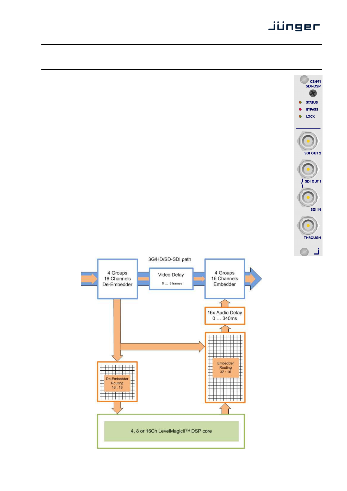
• 16 channel 3G/HD/SD-SDI de-embedder
• 16 in 16 de-embedder matrix
• 16 channel 3G/HD/SD-SDI embedder with video delay
• 32 in 16 embedder matrix
• video test generator
• variable audio delay of 340ms per embedder channel
• true peak brick wall limiters -20 …. 0dBTP threshold
• remote control via web server of C8702 Frame Controller, GPI/O, EmBER plus protocol
block diagram
C8491
C8491_manual_EN_150318.doc
Page 2

digital audio
modular
processing system
C8000
3G/HD/SD-SDI – DSP 4/8/16 audio channels
technical specifications
VIDEO:
Standard: SMPTE 425M 2.97 Gbit 3G-SDI Level A, B
SMPTE 292M 1.485 Gbit HD-SDI
SMPTE 259M 270 Mbit SD-SDI
Connection: BNC, 75 Ohm, coaxial (SDI through: active loop, re-clocked)
Signal Level: 800mV ±10% at 75Ώ
Equalisation: 130m (Belden 1694A, 2.97 GHz)
300m (Belden 8281, 270 MHz)
Return Loss: >15 dB (2.97 GHz)
Supported video standards:
3G 1080p 50 SMPTE 425M 3G 1080p60 SMPTE 425M
HD 720p 60 SMPTE 296M HD 1080p 30 SMPTE 274M
HD 720p 50 SMPTE 296M HD 1080p 25 SMPTE 274M
HD 720p 30 SMPTE 296M HD 1080p 24 SMPTE 295M
HD 720p 25 SMPTE 296M HD 1035i 60 SMPTE 260M
HD 720p 24 SMPTE 296M
HD 1080i 60 SMPTE 274M SD 525i/59.94 SMPTE 125M
HD 1080i 50 SMPTE 274M SD 625i/50 SMPTE 125M
HD 1080i 30 SMPTE 274M
all HD-standards are also supported with their 1/1001-frame-rates
Video Delay: 0 … 8 frames for interlaced formats (e.g. 625i50, 1080i59,94)
0 … 15 frames for progressive formats (e.g. 720p50, 720p60)
AUDIO:
Standards: SMPTE 272M (SD) / SMPTE 299M (HD)
Audio Data Format: 24 Bit, transparent for C-Bit and U-Bit according to AES3
Audio Sample Rate: 48 kHz synchronous to video-carrier (SD, HD, 3G)
32 kHz ... 48 kHz asynchronous to video-carrier (HD, 3G)
Latency: (de-embedder + embedder)
3G: < 600 µsec
HD: < 600 µsec
SD: < 2.0 msec
Audio Delay: 16 times 0 ...320 msec
GENERAL:
backplane connector: ref. to DIN41612, 64pin, a+b, male
power supply: +5V DC
power consumption: approx. 1.000 mA
dimension: 3RU, 4HP, 160mm depth
temperature: 10°C … 40 °C
humidity: 90%, non condensing
C8491
page 2/21
Page 3
digital audio
modular
processing system
C8000
3G/HD/SD-SDI – DSP 4/8/16 audio channels
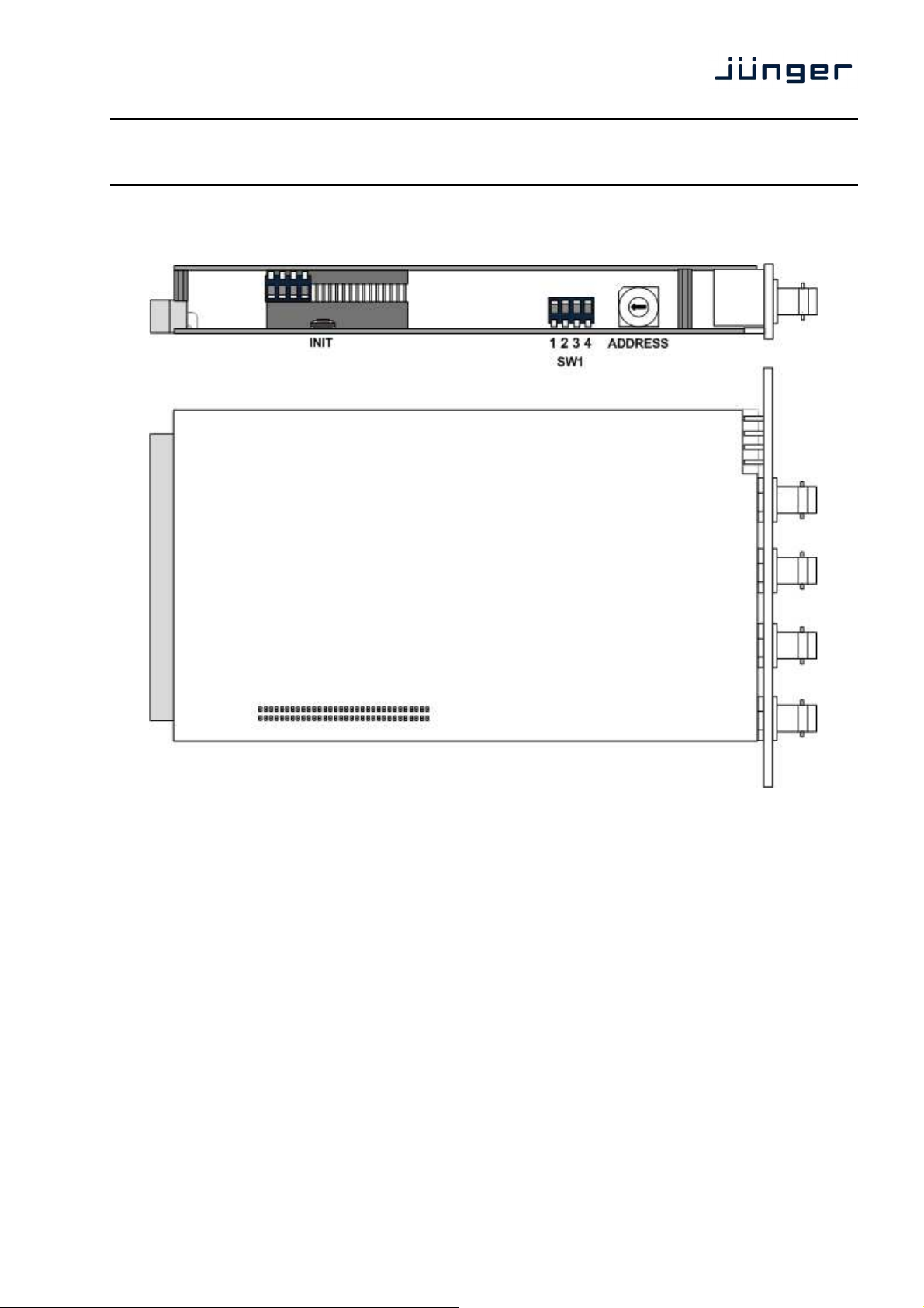
location of switches:
C8491
initial set up
ADDRESS: This rotary encoder sets the CAN ID of the C8491. The 16 switch positions
are hexadecimal numbers (0x0 to 0xF). The logical CAN address also
SW2:
#1 OFF internal use and must be set to OFF.
#2 OFF internal use and must be set to OFF.
#3 OFF internal use and must be set to OFF.
#4 ID +16 ON
CAN address range is extended by +16 (counting from 0x10 to 0x1F)
OFF
CAN address range is standard (counting from 0x0 to 0xF) see rotary
INIT Pressing the INIT button during power up will initialize the module
defines the place of the module icon within the GUI overview.
encoder settings below.
parameters to factory default values.
page 3/21
Page 4
digital audio
modular
processing system
C8000
3G/HD/SD-SDI – DSP 4/8/16 audio channels
C8491
General remark! The C8491 is a 16 channel device from the SDI de-embedding / embedding point of
view but the number of audio processing channels may be different.
Four channels are standard while 8 or 16 channels are an option. Since all parameters are the same for
each version, this document describes the 16 channel processor version. The difference will be the
number of fail over circuits (1 for the 4Ch, 2 for the 8Ch and 4 for the 16Ch option).
Another option is 5.1 surround processing. If this option is enabled one may also perform permanent
surround upmix or use the upmix for surround fail over.
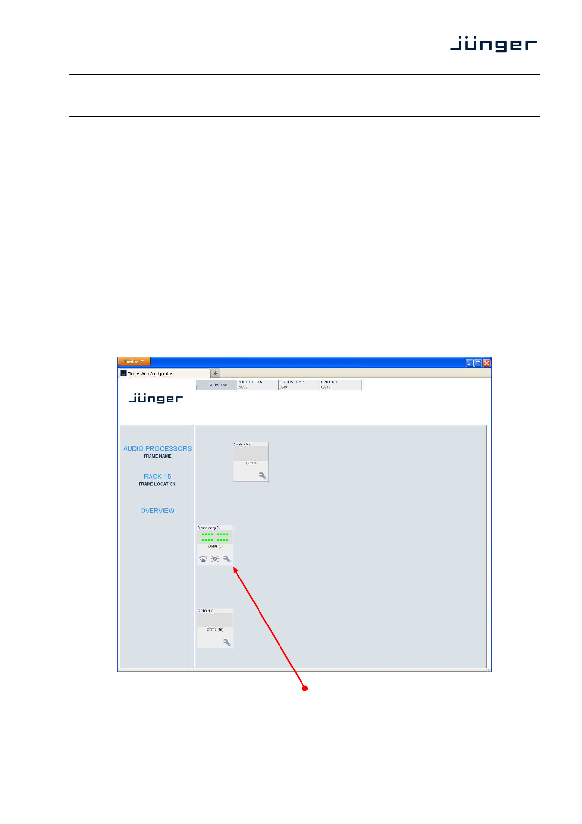
web browser based GUI
Set up of all configurations, parameters and functions via a web browser.
See also C8702 Frame Controller manual and respective firmware release notes.
OVERVIEW
The modules overview of a frame (below the display of an example frame):
By simply clicking on the spanner tool symbol you will get the control pages of the C8491 and the
status window on the left side, which is also shown on mouse over.
page 4/21
Page 5
digital audio
modular
processing system
C8000
3G/HD/SD-SDI – DSP 4/8/16 audio channels
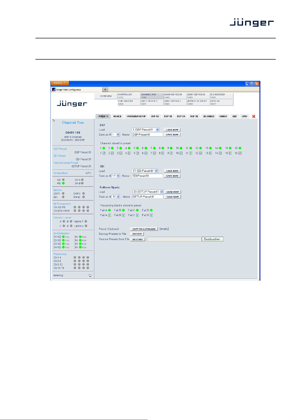
PRESETS
C8491
The C8491 has 3 banks of Presets. DSP Preset / SDI Preset / Failover/Upmix Preset.
The status window on the left hand side shows the names of the active presets. The word “modified”
will appear in line with the preset name, if any preset parameter was changed since loading this preset.
DSP is dedicated to audio processing (Leveler, Compressor / Limiter /
Load select a preset by name and press <LOAD NOW>.
Save as # select a preset NV memory number.
Name assign the preset a name (up to 16 digits).
and press <SAVE NOW>.
Expander).
page 5/21
Page 6
digital audio
modular
processing system
C8000
3G/HD/SD-SDI – DSP 4/8/16 audio channels
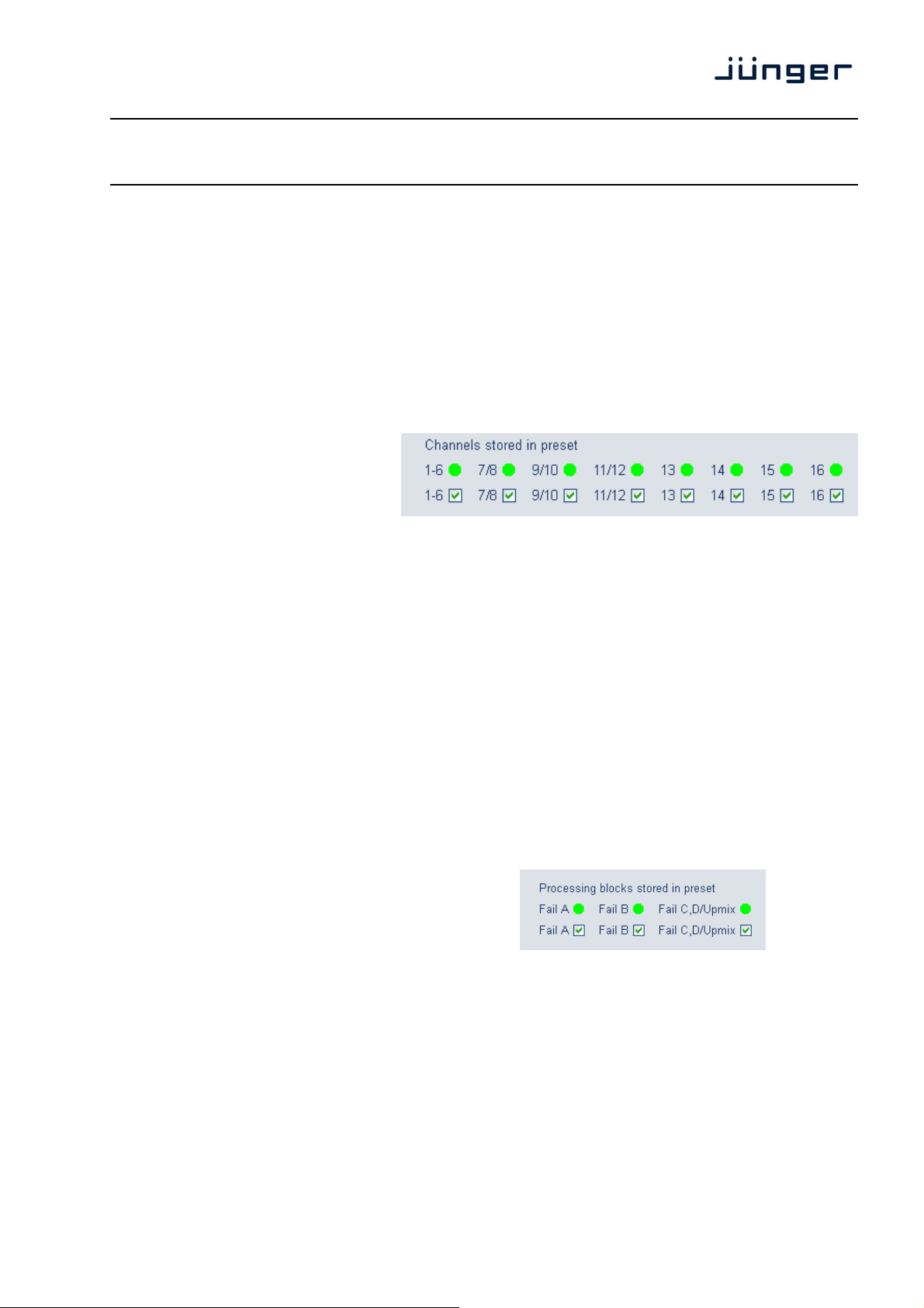
Channels stored the soft LEDs show the channels which will be controlled by the
in presets active preset. The check boxes define which channels will be
stored when you save a preset.
The total number of channels which will be displayed (upper soft
LED line) or masked (lower line of check boxes) depends on the
operating mode of the DSP and the link condition of the channels
Here an example for DSP1 (Ch 1 – 8) set for 5.1 + 2 operating
SDI controls the SDI Embedder / De-Embdder including delays
Load select a preset by name and press <LOAD NOW>.
Save as # select a preset NV memory number.
Name assign the preset a name (up to 16 digits).
and press <SAVE NOW>.
Failover / Upmix the third group (#33 … #40) is intended for fail over and upmix
Load select a preset by name and press <LOAD NOW>.
Save as # select a preset NV memory number.
Name assign the preset a name (up to 16 digits).
and press <SAVE NOW>.
Processing blocks you can select the processing blocks will be stored in a preset.
Stored in presets I.e. you can change the parameters for one 2ch fail over without
involved in a program.
mode and DSP 2 (Ch 9 – 16) is set for 4 x 2 operating mode
while Ch 9/10 and 11/12 are linked for stereo operation and
13 -14 as well as 15 – 16 are not linked.
parameters.
changing the parameters for another one:
C8491
The number of processing blocks involved, depends on the
operating mode for the DSPs.
Preset Clipboard copy the active preset to a clip board, the data may be used by
Backup Presets to File creates a backup XML file which may be saved on a PC.
other modules inside the same frame.
Restore Presets from File you can select a backup file from a PC and restore the set of
presets.
page 6/21
Page 7
digital audio
modular
processing system
C8000
3G/HD/SD-SDI – DSP 4/8/16 audio channels
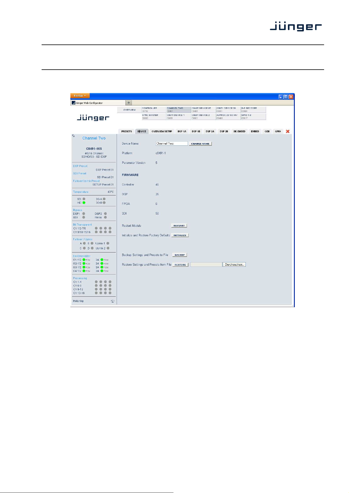
DEVICE
C8491
Device Name you can assign the module a name (up to 16 digits)
Platform [c8491-1]
Hardware platform of the module
Parameter Version [x]
The firmware of the module has undergone a few revisions where
some parameter have been added while others became obsolete.
Important Note! It is mandatory to initialize the module to factory defaults if the parameter version has
changed in order to clean the memory from rubbish data. Other wise you may experience male
functions
FIRMWARE displays the firmware versions of the C8491 components:
Controller the module controller
DSP the processing DSP
FPGA the routing and interface for the DSP
SDI the firmware of the SDI board
page 7/21
Page 8

digital audio
modular
processing system
C8000
3G/HD/SD-SDI – DSP 4/8/16 audio channels
Restart Module <RESTART> performs a warm start (soft reset)
Initialize and Restore <INITIALIZE> restores the factory default values for all
Factory Defaults parameters of the module including all presets.
You will loose your presets and settings. It's highly recommended
Backup Settings and <BACKUP> will put all active parameters and the content of all
Presets to File presets into an XML file. You may store such file on a PC.
Restore Settings and you may browse a matching XML file from a PC.
Presets from File <RESTORE> will overwrite all active parameters and the content of
to backup the settings and presets to a PC.
the presets with the content from the backup file.
C8491
page 8/21
Page 9

digital audio
modular
processing system
C8000
3G/HD/SD-SDI – DSP 4/8/16 audio channels
C8491
OVERVIEW/SETUP
This page shows the function blocks which are available for the respective programs. The display
depends on the program configuration of the DSPs. Below an example where DSP 1 is configured for
4 x 2 while DSP 2 is configured for 5.1 + 2 program processing:
SDI Bypass [Off / On]
You may bypass the audio de-embedder / embedder for testing or
Relay Bypass [Off / on]
The main SDi pass from SDI IN to SDI OUT 1 has a power fail
Relay Wait Time [3 … 60 seconds]
After Power Up In order to have the DSP operational and all module function block
Stream Select (3G-B) [Stream 1 / Stream 2]
For 3G-B SDI operation (see SMPTE 372 for details) you must
SNMP: Input Lost the monitoring of the physical SDI input can be disabled for the
trouble shooting purposes.
bypass relay. The relay may be turned off manually for testing or
trouble shooting purposes.
up and running before processing starts you may delay the moment
of switching on the signal path by x amount of seconds.
select which of the two streams runs through this particular module.
SNMP agent to prevent unwanted traps if the module is frequently
taken out of service.
page 9/21
Page 10

digital audio
modular
processing system
C8000
3G/HD/SD-SDI – DSP 4/8/16 audio channels
DSP 1A - 4 x 2 mode
From here you can control the audio parameters of the C8491 function blocks.
For detailed explanation of the LevelMagic parameters pls. see the separate document:
Junger_Processing-Parameters_xxyyzz.pdf which you may download from our web site.
C8491
Operating Mode [5.1 + 2 / 4 x 2]
defines the number of audio channels which are used for one audio
program. All relevant processing blocks will be configured to meet
Loudness Control Mode [Level / ITU BS.1770-1, -2, -3 / EBU R 128 / ARIB TR-B32
ATSC A/85 (2011 7 2013) / Free TV OP-59 / Porteria 354]
Bypass [On / Off]
the processing parameters will be bypassed to validate the actual
Link [Unlinked / Linked]
defines the coupling of the control circuits in order to maintain the
the selected mode.
settings. If enabled, the respective Bypass DSP1 or Bypass DSP2
soft LED turns red in the status panel.
listening balance for correlated signals or to provide a grouping of
the setup parameters for multi channel signals.
page 10/21
Page 11

digital audio
modular
processing system
C8000
3G/HD/SD-SDI – DSP 4/8/16 audio channels
Input [disable / enable]
Input Gain [-20 … +20 dB]
Leveler [disable / enable] turns off Transient Processor as well.
Loudness Target Level mode [0 … -50 dBFS]
ITU mode [0 … -50 LKFS]
EBU mode [0 … -50 LUFS]
Time [10, 20, 40 sec. / 1, 2, 5, 10, 20, 40 min / 1, 2 h]
Max Gain [0 … 40 dB]
Freeze Level [-20 … -60 dB]
Transient Processor
Max Gain [0 … 40 dB]
Response [soft, mid, hard]
Limiter [disable / enable]
Max True Peak [0.0 … -20 dBTP]
Profile (Leveler, Limiter)
Processing [live, speech, pop, uni, classic]
Expander [enable / disable]
Threshold [-60 … -20 dBFS]
Range [0.0 …. 20 dB, Gate]
Release Mode [0 … 9]
Compressor [enable / disable]
Reference Level [0 … -40 dBFS]
Range [0 … 8 …. 20 dB]
Ratio [1: 1.1 … 1: 4.0]
Processing [live, speech, pop, uni, classic]
Proc Status Enable [enable / disable]
if the average gain of the module is equal or above the Leveler
Bit Transparent [off / on]
indicates that a channel pair is in bit transparent mode
Max Gain for more than 10s the respective Processing Status
soft LED turns red. This status information is condensed for all
processing channels by the module controller. The frame controller
will condense the status information for all processing modules
within a frame and may generate a SNMP trap and/or fire a GPO.
In this case the SNMP manager may poll the frame for details to
“see” which processing channel sticks.
to let non audio signals pass through without the DSP processing
to maintain data structure for non audio signals.
C8491
page 11/21
Page 12

digital audio
modular
processing system
C8000
3G/HD/SD-SDI – DSP 4/8/16 audio channels
C8491
Expert [show / don't show]
The expert mode offers the possibility for manual intervention into the adaptive behavior of the
LevelMagic process for critical material. For details pls. see the above mentioned document.
Clear Processing History manually or GPI controlled
(Preset) [disable / enable]
defines if the switch is included in a preset. This allows to clear the
Initial Dynamic Gain [-40 … 1 … 15 dB]
start value for the LevelMagic process after Clear Processing
AGC Recovery [fast / slow]
Low Level Behavior
Processing Threshold [-80 … -70 … -20 dBFS]
the threshold from where the processing gain will behave as
Below Threshold Mode [release, hold]
returns slowly to 0 dB gain change or stays at the Processing
Metering if you click on the Metering icon at the left hand side in the
processing history if a preset is loaded.
History
defined by Below Threshold Mode.
Threshold
status window, a Java applet opens up. This feature is only
available if a valid Java virtual machine is running on the PC.
page 12/21
Page 13

digital audio
modular
processing system
C8000
3G/HD/SD-SDI – DSP 4/8/16 audio channels
DSP 1B – 4 x 2 mode
C8491
The C8491 offers the feature to use pairs of channels in a fail over mode. I.e. if the audio signal fails in
the first audio pair, the processor may switch over to the adjacent (e.g. 1/2 >> 3/4) pair automatically.
The functions of the circuits Failover A – Failover B are similar.
The switch over will be performed by a cross fade.
Failover A
Mode [Primary / Secondary / AUTO]
Dual Mono [off / auto]
if the fail over input is fed by a dual mono signal, the circuit may
Fail Threshold [-60 … -40 dBFS]
Fail Wait [1.5 … 10.0 sec.]
Fail Return [0.0 … 10.0 sec.]
Side Chain Filter [on / off]
a high pass filter (300 Hz) and a low pass filter (3000 Hz) is applied to
selection between both inputs and the auto mode.
automatically copy the opposite one if one fails
trigger threshold for the fail detector
time from detection of an audio loss to the moment of switch over
time from the detection of an audio return to the moment of switch
back
the detector side chain (not the audio path) to prevent hum and noise
from blocking fail over switching.
page 13/21
Page 14

digital audio
modular
processing system
C8000
3G/HD/SD-SDI – DSP 4/8/16 audio channels
DSP 2A – 5.1 + 2 mode
C8491
As mentioned above there is also a 5.1 + 2 program configuration available if one has bought the
surround option for the C8491. In this case the first 6 channels of the DSP are linked for surround
processing. This will also apply to DSP 1 if 5.1 + 2 is selected. The example above shows a condition
where the LFE is not linked to the other surround channels and may be controlled independently.
The remaining two channels may be used for an independent stereo audio program or fro two mono
channels.
Depending on the loudness control mode, the link options are different. While ITU defines a certain link
condition for loudness control and measurement, the proprietary Junger "Level" mode allows for more
detailed link variances. The screen shot below shows the most sophisticated MOVIE mode:
page 14/21
Page 15

digital audio
modular
processing system
C8000
3G/HD/SD-SDI – DSP 4/8/16 audio channels
C8491
DSP 2B – 5.1 + 2 mode
If you have bought the surround option you will get the option to do an upmix either for permanent
operation or as an fail over feature to maintain a surround image if the input surround signal
disappears. Also a downmix block is available that can be used to feed a stereo program path or it may
be used as a fail over source.
Beside the upmix algorithm the upmix block has a surround detector that will decide if an input
surround signal has disappeared under certain conditions:
Failover C [Primary / Secondary / AUTO]
It can be used to provide a two stage fail over in case of upmix.
The upmix source signal can be either the incoming L/R surround pair.
If this is driven by an upstream Dolby E decoder and the signal
changes from surround to PCM stereo this stereo will be used as an
upmix source. But it may also be desirable that in case surround fails a
different input must be used as the upmix source.
page 15/21
Page 16

digital audio
modular
processing system
C8000
3G/HD/SD-SDI – DSP 4/8/16 audio channels
Failover D [Prinmary / Secondary / AUTO]
The second fail over circuit can take the downmix as a failover source
in case the input signal fails. But it may simply put the downmix
permanently through (Mode switch is set to Secondary).
The other parameters are already described in the DSP 1B section.
Surround Detect
Switch [AUTO / FIX Surround / FIX Upmix]
You may turn on or off the upmix permanently or involve the surround
Detection [Center / Surround / Center or Surround / Signal loss]
here you set up which signals must be observed to detect a surround
Fail Threshold [-80 … -70 … -40 dBFS]
if the the RMS weighted input level drops below this value a fail signal
Fail Wait [0.0 … 10.0 seconds]
time until the fail condition becomes false after signal returns above
Downmix
Out Gain [-20 … 0 … 20 dB]
Center Mix Level [-12.0 … -3.0 … 0.0 dB]
Surround Mix Level [-12.0 … -3.0 … 0.0 dB]
Upmix
Enable [off / on]
Profile [Balanced / Front Projection]
Upmix Mode [Stereo / Mono]
tells the algorithm if the input signal may have correlated components
Process [slow / mid / fast]
reaction time of the upmix processes. For news, sports, shows with
Processing Time [3 … 100 ms]
the Look-Ahead Delay has great influence on the quality of the upmix
Center Divergance [0.0 … 0.5 … 1.0]
the upmix process assembles a center signal from the input stereo.
detector for auto switching.
source.
will be generated.
fail threshold.
or not.
permanently changing content (e.g. applause) setting "fast" is
recommended while mid / slow is recommended for music, movies.
process in regard to the latency of the process. The more time you
have to analyze the stereo signal the better the result for the upmix
signal will be. Depending on the system latency requirements (ingest
vs. live broadcast) you may change the processing time accordingly.
It may either be fed to the center channel only (0.0) or spread
between L/C/R (1.0). The effect will be a wider presentation of center
signals in a surround sound image.
C8491
page 16/21
Page 17

digital audio
modular
processing system
C8000
3G/HD/SD-SDI – DSP 4/8/16 audio channels
Surround Balance [0.0 … 0.5 … 1.0]
defines the amount of direct sound mixed into the surround channels.
0.0 provides pure ambient sound while 0.1 to 1.0 will increase the
Surround Gain [-24.0 … -12.0 … 0 dB]
sets the level of Ls/Rs channels.
LFE [on / off]
you may turn this option on if the upmix process must generate a
LFE Gain [-20.0 … 0.0 …. 20 dB]
Ch 15/16 Latency [off / on]
Compens.
DE-EMBEDDER
amount of direct sound.
subwoofer signal that will appear in the LFE channel.
C8491
Here you may assign the audio signals from the 16 de-embedded channels to
up to 16 processing channels. This display varies depending on the number of processing channels
which are enabled depending on the selected option for the C8491.
page 17/21
Page 18

digital audio
modular
processing system
C8000
3G/HD/SD-SDI – DSP 4/8/16 audio channels
EMBEDDER
C8491
From here you can control the embedder. You may select between the 16 audio channels from the
input (de-embedder) and the signals from the LevelMagic processor.
Video Delay [1 … 8 frames]
for compensating of processing delay especially if upmix is involved or
for other puposes you can apply up to 8 frmames of video dely. The
Generate New SDI [on / off]
Audio Structure if there is the need to replace the structure of the Ancillary Audio
Silence mutes the respective audio channel at the embedder side.
Delay [0 … 340 ms]
before the signals are embedded you may engage a delay per mono
amount of time depends on the video standard.
Data Blocks you can clean the whole area and generate a new
structure. This is an important feature to solve issues discovered from
time to time with legacy Embedders especially if it comes to SD-SDI. If
the option is checked, no group will be generated as long as no SDI
Out Grx is checked.
channel.
page 18/21
Page 19

digital audio
modular
processing system
C8000
3G/HD/SD-SDI – DSP 4/8/16 audio channels
Transparent [on / off]
Status Bits you can decide whether the AES Channel Status Bits are taken
Format : Professional
Audio Mode : Audio
Emphasis : None
Freq. Mode : Locked
Sample Freq. : 48kHz
Channel Mode : Not Indicated
User Bits : None
Auxiliary Bits : 24Bit
Audio Word Length : Not indicated
If the embedder detects a non audio signal it will set the "Audio Mode" to
GENERATOR
(transparent) from their source or if you want to generate new ones:
"Other" (non audio) and will set the validity bit for the AES stream.
C8491
SDI Generator [off / on / auto]
If the generator is turned "on", you can select one of the listed standards.
If the generator is set to "auto" and the input signal is lost, the generator
Test Pattern [Color Bars / Black Frame]
The generator can either generate 100% Color Bars or Black.
Video Standard You may select one of the above standards for the generator output.
Last The generator uses the last seen input format.
No Signal The generator output will be off.l
Important note! If the generator is turned on it operates on an internal quartz reference.
I.e. the signal is not synchronized to the SDI input.
will use the last valid input format. If no SDI was present since a power
cycle the output defaults to 720p60.
page 19/21
Page 20

digital audio
modular
processing system
C8000
3G/HD/SD-SDI – DSP 4/8/16 audio channels
C8491
GPIO
The C8491 has three sets of GPI/Os, the DSP, the SDI and the Setup/Failover GPI/Os. Moreover it
offers the function to clear the DSP history (see level magic expert parameters) by control of an
external device.
GPIs are useful if you want to recall settings remotely (e.g. by presets).
The C8k frame can handle 127 different GPIs. You must assign a
unique number to the respective function. Such numbers will be
generated by the brc8x Broadcast Remote Controller or by a GPI/O
interface module C8817. If the C8491 receives such a number over
the internal CAN bus, it will for example load the respective preset or it
will turn on a bypass function or clear the processing (DSP) history.
page 20/21
Page 21

digital audio
modular
processing system
C8000
3G/HD/SD-SDI – DSP 4/8/16 audio channels
C8491
GPOs (Tallies) may signal the status of a module through a GPO device.
This allows for easy interconnection with more generic monitoring
equipment. If an event occurs, the C8491 puts the assigned number
on the CAN bus so a C8817 GPI/O module or the brc8x may activate
their tallies.
page 21/21
 Loading...