

Page 1
digital audio
modular
C8000
processing system
3G/HD/SD SDI 16ch embedder/de-embedder
with video delay and VANC Dolby Metadata
features
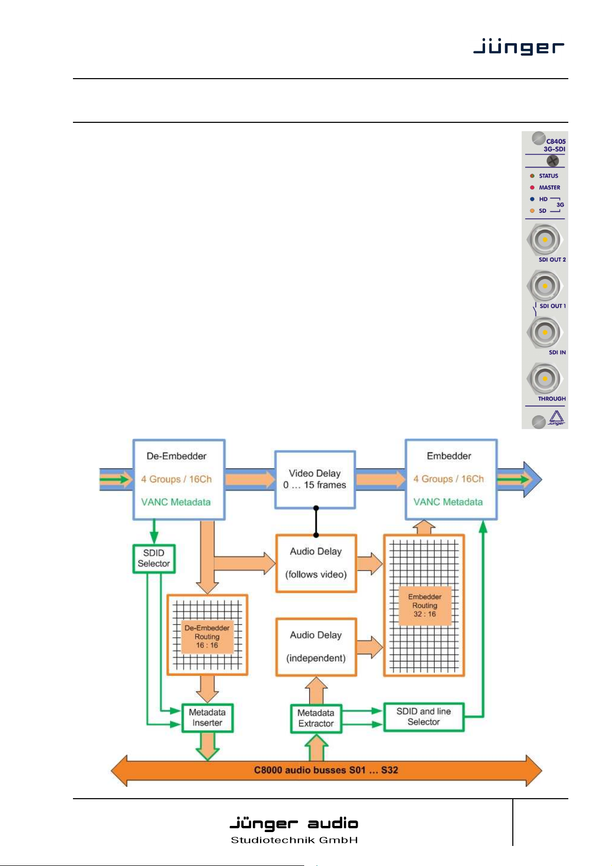
• BNC connectors : IN, THROUGH (active loop, re-clocked), OUT1, OUT2
• Bypass relay : connects SDI IN to SDI OUT1 for fail save operation
remote control via web interface and/or GPI
• De-Embedder : auto detection of 3G /HD / SD SDI
4 groups / 16 channels simultaneously
silence source
two VANC Dolby Metadata streams
• Embedder : 4 groups / 16 channels simultaneously
silence source
two VANC Dolby Metadata streams
• Video delay : 8 frames
• Audio delay: 16 x 320 ms for signals from c8k audio busses
automatic compensation of video delay for pass through audio
(from de-embedder to embedder)
• Bit transparent : for coded data streams (e.g. Dolby E)
• Video Generator : color bars or black
on/off manually or automatically if the input signal is lost
• Remote control : via C8702 frame controller
• Master mode : C8405 may deliver the clocks for the C8k Frame
block diagram
C8405
Jünger Audio-Studiotechnik GmbH
Justus-von-Liebig-Strasse 7
D -12489 Berlin
Germany
phone: +49-30-677721-0
fax: +49-30-677721-46
info@junger-audio.com
www.junger-audio.com
1/15
Page 2

digital audio
modular
C8000
processing system
3G/HD/SD SDI 16ch embedder/de-embedder
with video delay and VANC Dolby Metadata
technical specifications
VIDEO :
Standard : SMPTE 425M 2.97 Gbit 3G-SDI Level A, B
SMPTE 292M 1.485 Gbit HD-SDI
SMPTE 259M 270 Mbit SD-SDI
Connection : BNC, 75 Ohm, coaxial (SDI through: active loop, re-clocked)
Signal Level : 800mV ±10% at 75Ώ
Equalisation : 130m (Belden 1694A, 2.97 GHz)
300m (Belden 8281, 270 MHz)
Return Loss : >15 dB (2.97 GHz)
Supported video standards:
3G 1080p 50 SMPTE 425M 3G 1080p60 SMPTE 425M
HD 720p 60 SMPTE 296M HD 1080p 30 SMPTE 274M
HD 720p 50 SMPTE 296M HD 1080p 25 SMPTE 274M
HD 720p 30 SMPTE 296M HD 1080p 24 SMPTE 295M
HD 720p 25 SMPTE 296M HD 1035i 60 SMPTE 260M
HD 720p 24 SMPTE 296M
HD 1080i 60 SMPTE 274M SD 525i/59.94 SMPTE 125M
HD 1080i 50 SMPTE 274M SD 625i/50 SMPTE 125M
HD 1080i 30 SMPTE 274M
all HD-standards are also supported with their 1/1001-frame-rates
Video Delay: 0 … 15 frames 3G-, HD- SD-SDI
VANC METADATA : De-embedder and embedder for two serial (115.2 kbps) Dolby Metadata
streams each direction, according to SMPTE RDD6-2008
AUDIO :
Standards : SMPTE 272M (SD) / SMPTE 299M (HD)
Audio Data Format : 24 Bit, transparent for C-Bit and U-Bit according to AES3
Audio Sample Rate : 48 kHz synchronous to video-carrier (SD, HD, 3G)
32 kHz ... 48kHz asynchronous to video-carrier (HD, 3G)
Latency : (de-embedder + embedder)
3G : < 600µsec
HD : < 600µsec
SD : < 2.0msec
Audio Delay : 16 times 0 ...320 msec
GENERAL :
Backplane connector : ref. to DIN41612, 64pin, a+b, male
Power supply : +5V DC
Consumption : approx. 1.000mA
Dimension : 3RU, 4HP, 160mm depth
Temperature : 10°C … 40°C
Humidity : 90%, non condensing
Important Note! Do not place the C8405 close to either the power supplies or the side panel of the c8k
frame. Due to the high density of hot components on the PCB you may otherwise overheat the module.
C8405
Jünger Audio-Studiotechnik GmbH
Justus-von-Liebig-Strasse 7
D -12489 Berlin
Germany
phone: +49-30-677721-0
fax: +49-30-677721-46
info@junger-audio.com
www.junger-audio.com
2/15
Page 3
digital audio
modular
C8000
processing system
3G/HD/SD SDI 16ch embedder/de-embedder
with video delay and VANC Dolby Metadata
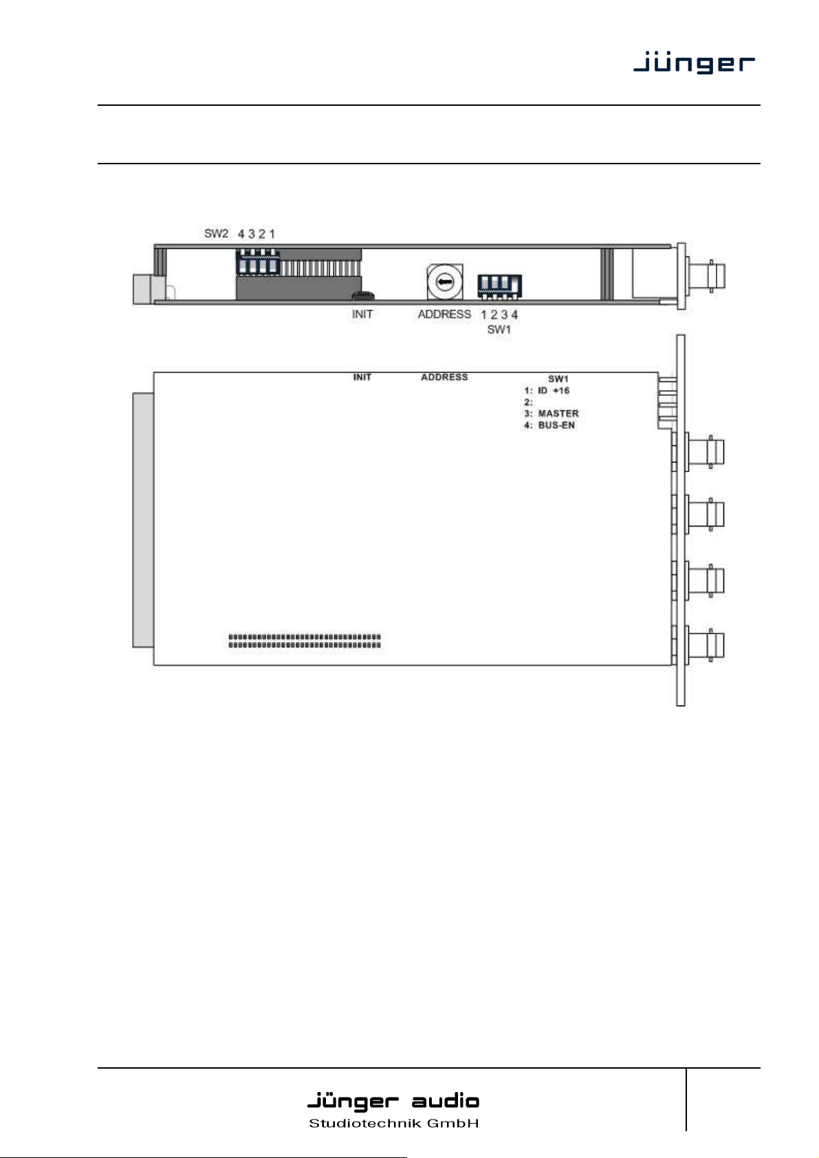
location of switches:
C8405
initial set up / bus assignment
For the initial setup the CAN address selection is the most important setting. To avoid address conflict
with other C8k modules the CAN address setting must be done with care.
See C8k System manual for details.
The MASTER MODE is important if the C8405 must deliver the audio clock for signal distribution within
the C8k frame.
The BUS-EN switch controls the driver circuits when power is turned on. This allows you to insert a new
module into an existing system without the risk of disturbing signals on other busses if the drivers are
disabled when the module is inserted into a frame with unknown bus configuration.
Jünger Audio-Studiotechnik GmbH
Justus-von-Liebig-Strasse 7
D -12489 Berlin
Germany
phone: +49-30-677721-0
fax: +49-30-677721-46
info@junger-audio.com
www.junger-audio.com
3/15
Page 4

digital audio
modular
C8000
processing system
3G/HD/SD SDI 16ch embedder/de-embedder
with video delay and VANC Dolby Metadata
switch settings
INIT Pressing the INIT button during power up will initialize the module
ADDRESS Set the CAN ADDR rotary encoder to an address, which is not in use by
SW1
1 = ID +16 ON
CAN address is extended by +16 (counting from 0x10 to 0x1F)
OFF
CAN address is standard (counting from 0x0 to 0xF)
2 = Not Used OFF
3 = MASTER: ON
The C8405 is clock master for the C8000 system
Important note! In Master Mode the C8405 must be inserted into one of the red color coded slots of
the C8k frame. Any other sync module must be removed from the frame in such a case!
For the C8934 Split-Frame there is no special slot.
OFF
Standard operation, no special care is needed
4 = BUS-EN: ON
Connects the outputs to the C8k audio buses on power up
OFF
Disconnects the module outputs from the C8k buses on power up
Important note! To avoid audio bus conflicts when you replace a C8405 or install an additional one
and the configuration is unknown, the output bus drivers must be disabled before inserting it. If all
settings are done remotely and the unit fits into the bus assignment scheme of a frame, you must
remove it and place the switch back into position BUS-EN=ON.
SW2
1 = Not Used OFF
2 = Not Used OFF
3 = Not Used OFF
4 = HD progressive
switching mode ON
for progressive HD formats carrying Dolby E signals, it is mandatory to switch
parameters to factory default values.
another module of a C8000 frame (for details regarding CAN addressing,
see C8000 system manual).
only every second HD frame, because a Dolby E data frame spans over two
progressive video frames. Otherwise one may cut the Dolby E data frame
present at the switching moment in the middle resulting in audio noise after
decoding. Dolby recommends to use a synchronous BB as a reference for
the switching point. In this case the system must be synchronized by a C8830
and the C8405 must not be set to master mode!
In addition to that, SW2-4 must turned ON to use the V-sync derived from the
BB to act as the switching point reference for the internal matrix as well,
instead of the SDI frame reference itself.
C8405
Jünger Audio-Studiotechnik GmbH
Justus-von-Liebig-Strasse 7
D -12489 Berlin
Germany
phone: +49-30-677721-0
fax: +49-30-677721-46
info@junger-audio.com
www.junger-audio.com
4/15
Page 5
digital audio
modular
C8000
processing system
3G/HD/SD SDI 16ch embedder/de-embedder
with video delay and VANC Dolby Metadata
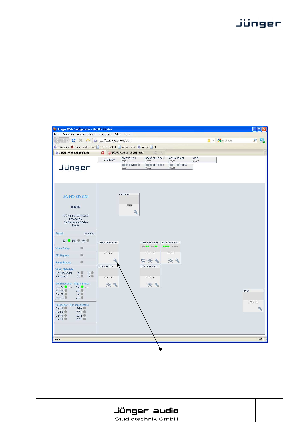
web browser based GUI
Set up of all configurations, parameters and functions via a web browser.
See also C8702 Frame Controller manual.
OVERVIEW
The modules overview of a frame (below the display of an example frame) :
C8405
By simply clicking on the spanner tool symbol you will get the control pages of the C8405 and
the status window on the left side, which you will also see on mouse over.
The entrance to the module setup is the PRESET page:
Jünger Audio-Studiotechnik GmbH
Justus-von-Liebig-Strasse 7
D -12489 Berlin
Germany
phone: +49-30-677721-0
fax: +49-30-677721-46
info@junger-audio.com
www.junger-audio.com
5/15
Page 6

digital audio
modular
C8000
processing system
3G/HD/SD SDI 16ch embedder/de-embedder
with video delay and VANC Dolby Metadata
PRESETS
C8405
The C8405 has 16 Presets. These Presets are named PRESET 01 to PRESET 16 by default. The
status window at the left hand side shows the name of the active preset. The word “modified:” will
appear in line with the Preset name, if a preset parameter was changed by the operator.
Load Preset select a preset by name and press <LOAD NOW>
Save as Preset # select a preset memory number
Name assign the preset a 16 digit name and press <SAVE NOW>
Preset Clipboard copy the active preset to a clip board, The data may be used by other
Backup Presets to File creates a backup XML file which may be stored to the PC
Restore Presets from File you can select a backup file from the PC.
Jünger Audio-Studiotechnik GmbH
Justus-von-Liebig-Strasse 7
D -12489 Berlin
Germany
modules inside the same frame.
phone: +49-30-677721-0
fax: +49-30-677721-46
info@junger-audio.com
www.junger-audio.com
6/15
Page 7

digital audio
modular
C8000
processing system
3G/HD/SD SDI 16ch embedder/de-embedder
with video delay and VANC Dolby Metadata
DEVICE
C8405
On the DEVICE page you can assign a 16 digit name to the module, perform a warm start by
pressing <RESTART> or initialize the module to factory default settings by pressing <INITIALIZE>.
You can BACKUP / RESTORE all module settings and parameters including presets as well as the
actual set of parameters used by the module controller.
FIRMWARE Controller the firmware of the module controller
SDI the firmware of the SDI part
FPGA the version of the FPGA on the audio board
Jünger Audio-Studiotechnik GmbH
Justus-von-Liebig-Strasse 7
D -12489 Berlin
Germany
phone: +49-30-677721-0
fax: +49-30-677721-46
info@junger-audio.com
www.junger-audio.com
7/15
Page 8

digital audio
modular
C8000
processing system
3G/HD/SD SDI 16ch embedder/de-embedder
with video delay and VANC Dolby Metadata
DE-EMBEDDER
C8405
On the DE-EMBBEDER page you will get a matrix overview of the signals which are extracted from
the SDI data stream and sent to the C8k audio frame bus. The de-embedder can route all of the 16
embedded audio channels in any combination to the C8k audio busses.
In addition to the 16 signals from the 4 groups, a Silence source is provided.
8 channels may be grouped and sent in 8CH Multiplex Mode over one bus line.
You can enable / disable the Bus Drivers to set up the module without interference with other
modules already installed.
Jünger Audio-Studiotechnik GmbH
Justus-von-Liebig-Strasse 7
D -12489 Berlin
Germany
phone: +49-30-677721-0
fax: +49-30-677721-46
info@junger-audio.com
www.junger-audio.com
8/15
Page 9

digital audio
modular
C8000
processing system
3G/HD/SD SDI 16ch embedder/de-embedder
with video delay and VANC Dolby Metadata
VANC Metadata
The C8405 may receive, decode and insert VANC Dolby Metadata into the c8k Metadata
distribution system for use by other modules inside a frame.
The transport of Dolby Metadata embedded into the Vertical Ancilliary data space of an SDI signal is
defined by SMPTE 2020 suite of standards. For details pls refer to such documents.
In general the mechanism may provide up to eight independent Dolby Metadata Streams. The
format of the streams is asynchronous data like one will find on the Dolby 9-pin serial Metadata
Interface of the Dolby decoders and encoders as well as the C8601 Dolby E/D decoder, the C8611
Dolby E encoder and the C8612 Dolby D/D+ encoder from Junger Audio.
The streams are identified by a DID Data Identifier (value 0x45). Each individual stream is identified
by its Secondary Data Identifier SDID. The SDIDs range from 1 to 9.
SDID 2 – 9 are used to identify the streams associated with a respective program. The SDID
number also tells which embedded audio signal pair (e.g. G1-1/2) carries the first pair of audio
channels for that program. The rule is that further audio channels belonging to the same program
must be embedded in consecutive order.
SDID 0x01 identifies a Dolby Metadata stream that is not associated with an audio channel pair and
may be used if only one VANC stream is embedded.
The Junger Audio system allows to de-embed up to two independent VANC Dolby Metadata
streams named A and B. You can select the respective SDID for the de-embedder.
The table at the bottom of the DE-EMBEDDER page shows the VANC streams found in an
embedded signal :
C8405
Via the VANC de-embedder routing you may link the respective Metadata to their audio channels.
The Junger Audio Metadata system inside the c8k frame makes use of the ASE User Bits to move
Metadata to other modules. If you disable the VANC routing these User Bits are transparent again
and carry the information from their source somewhere upstream.
The status panel at the left hand side in the GUI shows if the pre selected stream carries valid
Metadata (green) or not (red) :
Jünger Audio-Studiotechnik GmbH
Justus-von-Liebig-Strasse 7
D -12489 Berlin
Germany
phone: +49-30-677721-0
fax: +49-30-677721-46
info@junger-audio.com
www.junger-audio.com
9/15
Page 10

digital audio
modular
C8000
processing system
3G/HD/SD SDI 16ch embedder/de-embedder
with video delay and VANC Dolby Metadata
EMBEDDER
C8405
The EMBEDDER page is a little more complex because it allows routing within the SDI domain as
well as in any combination with signals returned from the audio busses.
A word on embedding There are two principle methods to embed audio. First of all you can
leave the Ancillary Audio Data structure as it is and simply replace
the audio samples. If there is no Group existing from the input you must
build a new one and place it somewhere in the Ancillary Data area.
Unfortunately SMPTE left room for freedom where to place the data.
This may cause fragmented data blocks after the embedding process,
with wrong parts left over. If this is the case a downstream
de-embedder will be confused and may reassemble the audio samples
in a wrong way causing distortion.
That’s why the C8405 offers a mode where you can clean up the
incoming data structure and generate a new one.
Jünger Audio-Studiotechnik GmbH
Justus-von-Liebig-Strasse 7
D -12489 Berlin
Germany
phone: +49-30-677721-0
fax: +49-30-677721-46
info@junger-audio.com
www.junger-audio.com
10/15
Page 11

digital audio
modular
C8000
processing system
3G/HD/SD SDI 16ch embedder/de-embedder
with video delay and VANC Dolby Metadata
Video Delay For compensation of any kind of audio processing delay within the
chain of devices you may use a Video Delay.
Important note! The video delay is a static setting. I.e. you must not change it on air! This will
cause a resynchronization of the SDI stream. Since the video delay is part of the presets, you must
be careful when creating presets to use the same value in all presets!
Generate new SDI If there is the need to replace the structure of the Ancillary Audio
Audio Structure Data Blocks you can clean the whole area and generate a new
SDI Out Grx This check box enables each of the 4 SDI audio groups to be used
Silence Mutes the respective audio channel at the embedder side.
Delay The inputs of the embedder routing matrix can be taken either
from the de-embedder or from the C8k audio busses in any
For signals coming from the C8k audio busses an independent delay
Important note! These delay settings are also static. You must not use this feature if you shuffle
audio signals with different delay times. It will cause strange effects at the moment of switching,
because the delay length is changing!
Mux Format The signals from the C8k audio busses may be received in 2CH or
Generate new Status Bits For the signals coming from the C8k audio busses, you can decide
In this case the Channel Status will be set to:
VANC Metadata the VAC Dolby Metadata embedder allows you to embed two
You can select a line where the Metadata must be embedded or you
Position “0” turns the delay function off.
structure. If the option is checked, there will be no signal available at
the group output as long as there is no SDI Out Grx checked.
individually by the C8405 embedder. If it is not checked and “Generate
new SDI Audio Structure” is not enabled, the audio data from the
input will travel untouched from the SDI input to the output.
combination. If they are taken from the de-embedder and a Video
Delay is introduced, the Video Delay will automatically be
compensated for those signals.
per single channel may be used.
8CH multiplex mode. If they must be received in 8CH multiplex mode
there is only one bus selector available for each of the two eight
channel groups.
whether the AES Channel Status Bits are taken from their source or if
you want to generate new ones.
Format : Professional
Audio Mode : Audio
Emphasis : None
Freq. Mode : Locked
Sample Freq. : 48kHz
Channel Mode : Not Indicated
User Bits : None
Auxiliary Bits : 24Bit
Audio Word Length : Not indicated
independent Metadata streams C and D. You may assign each stream
an independent SDID (see page 9 for details). The Metadata to be
embedded are extracted from the User Bits of the audio data received
by the respective c8k audio busses.
can leave it in “auto” mode. In this case the next possible line that has
nothing embedded will be selected.
C8405
Jünger Audio-Studiotechnik GmbH
Justus-von-Liebig-Strasse 7
D -12489 Berlin
Germany
phone: +49-30-677721-0
fax: +49-30-677721-46
info@junger-audio.com
www.junger-audio.com
11/15
Page 12

digital audio
modular
C8000
processing system
3G/HD/SD SDI 16ch embedder/de-embedder
with video delay and VANC Dolby Metadata
SETUP
C8405
From here you can set up several hardware related functions :
SDI Bypass will pass the embedded audio data from the de-embedder
to the embedder 1:1. This function preserves the original
Relay Bypass will deactivate the Bypass Relay. It provides a short cut from
SDI-IN to SDI-OUT1 and disconnects the de-embedder
SNMP: Input lost the monitoring function of the physical SDI can be disabled for the
Jünger Audio-Studiotechnik GmbH
Justus-von-Liebig-Strasse 7
D -12489 Berlin
Germany
Ancillary Data structure.
from the SDI input. This relay also serves as a fail bypass if the power
is off. This feature maintains the SDI signal for downstream equipment.
SNMP agent, to prevent from unwanted traps if the module is
frequently taken out of service. The SDI status display within the GUI is
not affected.
phone: +49-30-677721-0
fax: +49-30-677721-46
info@junger-audio.com
www.junger-audio.com
12/15
Page 13

digital audio
modular
C8000
processing system
3G/HD/SD SDI 16ch embedder/de-embedder
with video delay and VANC Dolby Metadata
Relay Wait Time the time from powering the C8405 up till the relay is engaged.
After Power Up To avoid audio interruptions you should not engage the relay before
you are sure that all other equipment in the signal chain is up and
running. Because this is an asynchronous process the relay switch over
Error Detection The serial audio data from the frame bus can be monitored for proper
The bus status as well as the SDI input status may be presented to
Main Input This is a display of the audio busses which have been assigned at the
Aternative Input For automatic bypass of a (e.g. faulty) processing module or switching
Auto Mode Enables the automatic switch over in case an error is detected for the
Important Note! Auto Mode is possible only if Error Detection is turned on.
<TEST> The soft button may be used for testing the switch over function.
causes a glitch in the SDI signal.
positioning of an Error-Flag. A bad Error-Flag is an indication that
there is disturbance upstream (input signal, input module,
DSP module).
The Error Detection can be turned Off and On for each input from the
bus. You will see the status on the left hand side:
“Embedder (Bus Status)”. A grey “LED” shows that the detection is
disabled. While green is OK, red indicates an error condition and
yellow indicates a Non Audio signal (e.g. Dolby E stream).
external monitoring systems via SNMP. The frame controller
summarizes such status information and generates SNMP traps for
the frame as an entity or may activate GPOs (if GPI/O module(s) are
installed). The SNMP manager may afterwards poll the
“modulesStatus” for more detailed status information per input
(see SNMP documentation for details).
EMBEDDER page.
over to an emergency announcement you may set up alternative
inputs. Switch over may be tested with the TEST button.
Main Input.
C8405
Jünger Audio-Studiotechnik GmbH
Justus-von-Liebig-Strasse 7
D -12489 Berlin
Germany
phone: +49-30-677721-0
fax: +49-30-677721-46
info@junger-audio.com
www.junger-audio.com
13/15
Page 14

digital audio
modular
C8000
processing system
3G/HD/SD SDI 16ch embedder/de-embedder
with video delay and VANC Dolby Metadata
GENERATOR
C8405
Generator enabled The video generator may be enabled here. The video format it
Test Pattern If the Generator is on, it will generate one of the two video test patterns
Video Format If the Automatic mode is selected and the Generator is enabled, it
Important note! If the generator is on, either in manual or in automatic mode, it operates on an
internal quartz reference. It is not possible to genlock it to an external reference.
The SDI input will be ignored but you may embed signals from the C8k audio busses for testing
purpose or you can use the SDI stream as a carrier to send 16 audio channels from A to B over one
coax cable.
Jünger Audio-Studiotechnik GmbH
Justus-von-Liebig-Strasse 7
D -12489 Berlin
Germany
generates depends on the selection below.
either black or 100% color bar.
turns on if the SDI input signal fails. In this case it will generate the
same video format as the previous input signal.
If “Generator enabled” is checked and if you have selected one of the
Video Formats the Generator will be turned on using this format.
phone: +49-30-677721-0
fax: +49-30-677721-46
info@junger-audio.com
www.junger-audio.com
14/15
Page 15

digital audio
modular
C8000
processing system
3G/HD/SD SDI 16ch embedder/de-embedder
with video delay and VANC Dolby Metadata
GPI/O
C8405
GPIs are useful if you want to recall settings remotely e.g. by presets.
The C8k frame can handle 127 different GPIs. You must assign a unique number to the
respective function. Such numbers will be generated by the brc8x Broadcast Remote Controller
or by a GPI/O interface module GPO (see C8817 manual for details). If the C8405 receives
such a number it will for example load the respective preset or will turn the generator on.
GPOs (Tallies) may signal the status of a module. The GPI/O module permanently listens for
such numbers. If it reads such a number it will engage the respective GPO (see C8817 manual
for details). This allows for easy interconnection with more generic monitoring equipment.
Jünger Audio-Studiotechnik GmbH
Justus-von-Liebig-Strasse 7
D -12489 Berlin
Germany
phone: +49-30-677721-0
fax: +49-30-677721-46
info@junger-audio.com
www.junger-audio.com
15/15
 Loading...