

Page 1
digital audio
modular
C8000
processing system
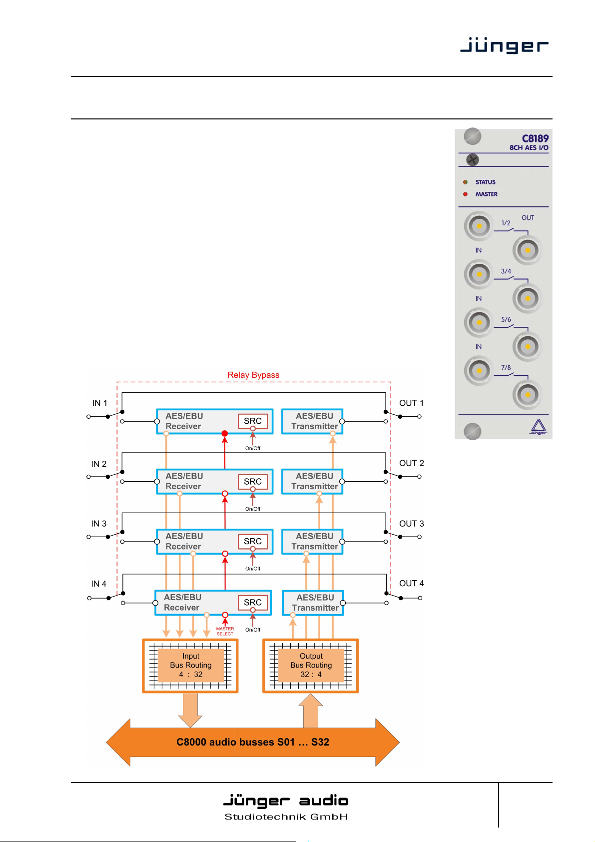
4 Channel unbalanced AES/EBU I/O
features
• 4 unbalanced AES inputs
• Input Sample Rate Converters (SRC)
• 4 unbalanced AES outputs
• Relay bypass for pairs of I/Os
• Relay wait time after power up
• Master mode (clock master for the frame)
• 75Ohm BNC connectors
• Remote control via C8702 Frame Controller, or http based API
block diagram
C8189
Jünger Audio Studiotechnik GmbH
Justus-von-Liebig-Strasse 7
D -12489 Berlin
Germany
phone: +49-30-677721-0
fax: +49-30-677721-46
info@junger-audio.com
www.junger-audio.com
1/10
Page 2

digital audio
modular
C8000
processing system
4 Channel unbalanced AES/EBU I/O
C8189
technical specifications
AUDIO :
resolution : 24bit
sample rate : 32...48kHz
format: AES3id
Input level : 0,3 … 5Vpp
Output level : 1,0Vpp at 75Ohm
GENERAL :
I/O connector BNC / 75Ohm
backplane connector : ref. to DIN41612, 64pin, a+b, male
power supply : +5V DC
power consumption : approx. 1.000mA
dimension : 3RU, 4HP, 160mm depth
temperature : 10°C … 40°C
humidity : 90%, non condensing
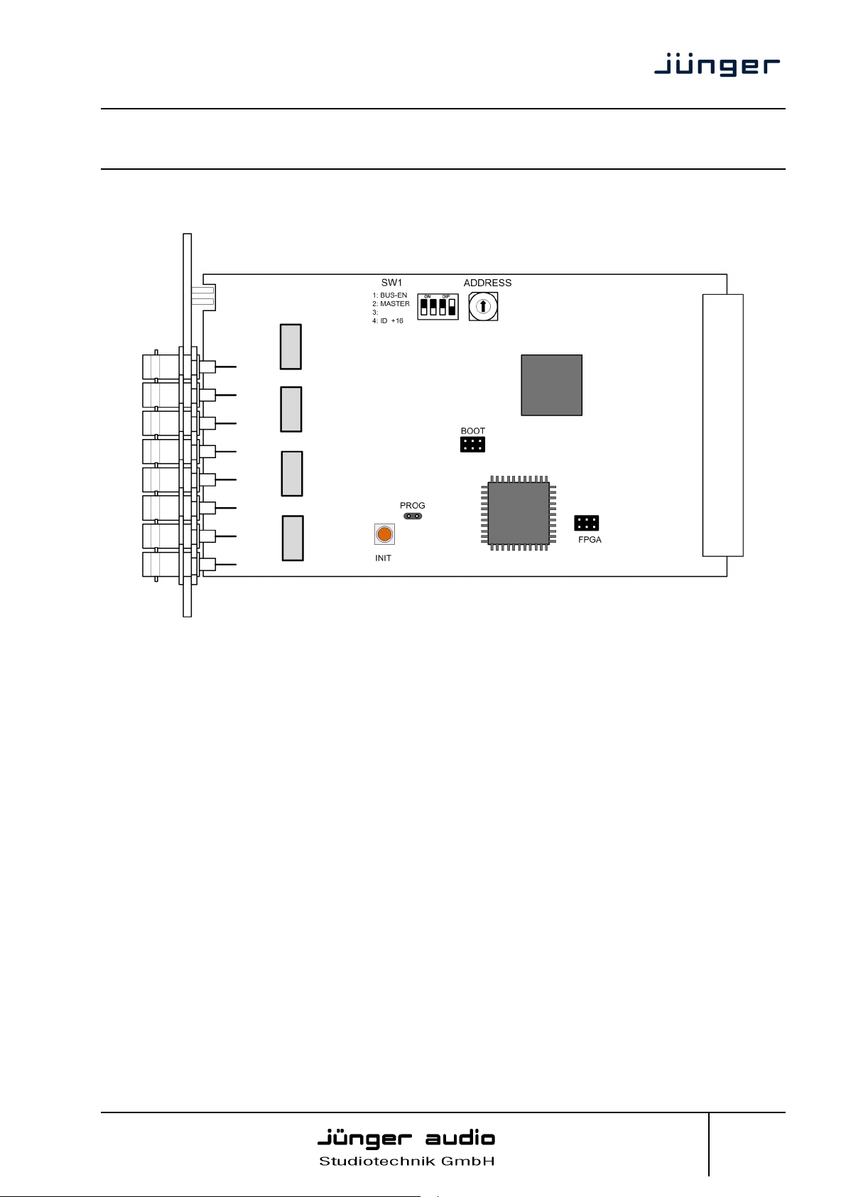
hardware settings
The C8189 does not have front panel controls. It may be configured via a DIP switch and a rotary
encoder. On the front panel there are two LEDs with different display modes:
STATUS
green = status OK
flashing = the module is under control of the Frame Controller
red = status is bad, remote reading of the status via GUI is required.
It is likely that the Frame Controller has issued a SNMP trap.
MASTER
Off = the audio bus interface clock must be provided by the frame
red = the 8188 is clock master for the frame
Jünger Audio Studiotechnik GmbH
Justus-von-Liebig-Strasse 7
D -12489 Berlin
Germany
phone: +49-30-677721-0
fax: +49-30-677721-46
info@junger-audio.com
www.junger-audio.com
2/10
Page 3
digital audio
modular
processing system
4 Channel unbalanced AES/EBU I/O
location of switches:
C8000
C8189
switch settings
BUS-EN: ON
automatically connects the outputs to the C8k audio buses on power up.
The output configuration will be taken from the NV (non volatile) memory.
OFF
disconnects the module outputs from the C8k buses on power up.
MASTER: ON
the module is clock master for a C8932 frame
OFF
an other module is sync master for the frame
#3 not used
ID +16 ON
CAN address range is extended by +16, counting from 0x10 to 0x1F
(16 – 31)
OFF
CAN address ranges from 0x0 to 0xF (0 – 15)
Jünger Audio Studiotechnik GmbH
Justus-von-Liebig-Strasse 7
D -12489 Berlin
Germany
phone: +49-30-677721-0
fax: +49-30-677721-46
info@junger-audio.com
www.junger-audio.com
3/10
Page 4

digital audio
modular
C8000
processing system
4 Channel unbalanced AES/EBU I/O
C8189
rotary encoder settings
ADDRESS 0 – F
sets the CAN ID . The 16 switch positions are hexadecimal numbers (0x0
to 0xF). Each module within a frame must be assigned a unique CAN
bus address for proper communication with other modules of the frame.
Important note! To avoid audio bus conflicts when you replace a module or install an additional one and
the configuration is unknown, the output bus drivers must be disabled by BUS-EN=OFF before inserting it.
If all settings are done remotely and the unit fits into the bus assignment scheme of a frame, you must
remove it and place the switch back into position BUS-EN=ON.
INIT the button initializes the module to factory default if one holds it down
while power up.
Jünger Audio Studiotechnik GmbH
Justus-von-Liebig-Strasse 7
D -12489 Berlin
Germany
phone: +49-30-677721-0
fax: +49-30-677721-46
info@junger-audio.com
www.junger-audio.com
4/10
Page 5

digital audio
modular
C8000
processing system
4 Channel unbalanced AES/EBU I/O
web browser based GUI
Set up of all configurations, parameters and functions via a web browser.
See also C8702 Frame Controller manual
OVERVIEW
The modules overview of a frame (below the display of an example frame) :
C8189
By simply clicking on the spanner tool symbol you will get the control pages of the C8189 and
the status window on the left side, which you will also see on mouse over.
The entrance to the module setup is the PRESET page:
Jünger Audio Studiotechnik GmbH
Justus-von-Liebig-Strasse 7
D -12489 Berlin
Germany
phone: +49-30-677721-0
fax: +49-30-677721-46
info@junger-audio.com
www.junger-audio.com
5/10
Page 6

digital audio
modular
processing system
4 Channel unbalanced AES/EBU I/O
PRESET
C8000
C8189
Input Bus Routing for flexible signal routing you may change the input bus configuration by
Load will load one of the available presets from the modules NV memory
Save as # Name here you can select a Preset Number (memory location) and
assign the preset a 16 character name
Preset Clipboard you can copy the data of the active parameters to a clip board
and paste such data into the preset memory of another module
within one frame
Backup Presets to File store all presets of one C8082 into a file
Restore Presets from File restore all presets for a C8082 from a file
Jünger Audio Studiotechnik GmbH
Justus-von-Liebig-Strasse 7
D -12489 Berlin
Germany
one of the 8 Presets
phone: +49-30-677721-0
fax: +49-30-677721-46
info@junger-audio.com
www.junger-audio.com
6/10
Page 7

digital audio
modular
processing system
4 Channel unbalanced AES/EBU I/O
DEVICE
C8000
C8189
Device Name a 16 character device name can be set
Firmware
Controller firmware version of the built-in module controller
FPGA firmware of the FPGA
Restart Module warm starts the module (like a reset)
Initialize …. recalls factory default settings for parameters, presets, bus routing etc.
Backup will store all module data from its NV-memory to file
Restore will restore module data from file to its NV-memory
Jünger Audio Studiotechnik GmbH
Justus-von-Liebig-Strasse 7
D -12489 Berlin
Germany
phone: +49-30-677721-0
fax: +49-30-677721-46
info@junger-audio.com
www.junger-audio.com
7/10
Page 8

digital audio
modular
processing system
4 Channel unbalanced AES/EBU I/O
SETUP / ROUTING
C8000
C8189
Relay Bypass the AES I/Os provide a relay for each pair, which may be turned off with
Relay Wait Time the Relay Bypass is active as long as the module has no power.
After Power Up If power is turned on, the module will wait this amount of time before
Jünger Audio Studiotechnik GmbH
Justus-von-Liebig-Strasse 7
D -12489 Berlin
Germany
this switch, i.e. the I/Os are put in Relay Bypass mode.
the relays are engaged to disable Relay Bypass.
phone: +49-30-677721-0
fax: +49-30-677721-46
info@junger-audio.com
www.junger-audio.com
8/10
Page 9

digital audio
modular
C8000
processing system
4 Channel unbalanced AES/EBU I/O
C8189
MASTER SELECT if the module is turned into Master mode by SW1, you may select here
one of the four AES inputs as the actual MASTER input. In this case
the clock reference of that input will be used to synchronize the whole
C8932 or an island of the C8934 frame.
Important note! For a C8932 frame the C8189 must be placed into one of the slots marked red and no
other sync source (e.g. C8830) must be installed.
Sample rate Converter it is possible to turn on a SRC for that AES input.
to C8000 Bus here you assign the audio signals from the AES inputs to c8k busses
8ch Mux sends all 4 signal pairs on one bus line
Ch 1/2 … Ch 7/8 sends a pair of input signals to one bus line
Enable Bus Drivers turns on all module bus drivers (from tri state mode to active).
from C8000 Bus here you assign the signals from the c8k bus to the AES outputs
8ch Mux receives 8 channels from one bus line. The assignment of pairs to the
AES outputs must be done by the respective check boxes
Ch 1/2… Ch 7/8 receives a pair of signals from the c8k bus
Transparent Status Bits if not checked the Channel Status of the AES transmitter will be set to:
Format : Professional
Audio Mode : Audio
Emphasis : None
Freq. Mode : Locked
Sample Freq. : 48kHz
Channel Mode : Not Indicated
User Bits : None
Auxiliary Bits : 24Bit
Audio Word Length : Not indicated
AES Input Error Detection the status of the AES inputs can be monitored for AES signal present
and for 3 detailed error types:
Lock AES receiver lock status
Validity AES3 validity bit detected
Parity AES parity (data errors detection)
You can mask each AES input for error detection:
grey - error detection disabled
green - no error detected / PCM audio
yellow - no error detected / non audio (Dolby E, D)
red - indicates an error condition.
Bus Error Detection the serial audio data from the frame bus can be monitored for proper
positioning of an Error-Flag. A bad Error-Flag is an indication that
there is disturbance upstream (input signal, input module,
other DSP module). The Error Detection can be turned Off and On for
each input from the bus. You will see the Bus Status on the left hand
side as a soft LED.
grey - error detection is disabled
green - no error detected / PCM
yellow - no error detected / non audio (Dolby E, D)
The bus status may also be presented to external monitoring systems
Jünger Audio Studiotechnik GmbH
Justus-von-Liebig-Strasse 7
D -12489 Berlin
Germany
red - indicates an error condition.
via SNMP.
phone: +49-30-677721-0
fax: +49-30-677721-46
info@junger-audio.com
www.junger-audio.com
9/10
Page 10

digital audio
modular
processing system
4 Channel unbalanced AES/EBU I/O
GPO
C8000
C8189
GPOs (Tallies) may signal the status of a module by means of relay switches. Those
relays have NO (normally open) as well as NC (normally closed)
contacts. This allows easy interconnection with more generic
monitoring equipment. If an event occurs the C8189 puts the assigned
number on the CAN bus so a C8817 GPI/O module or the brc8x may
turn on a relay or button LEDs (see C8817 manual for details).
Jünger Audio Studiotechnik GmbH
Justus-von-Liebig-Strasse 7
D -12489 Berlin
Germany
phone: +49-30-677721-0
fax: +49-30-677721-46
info@junger-audio.com
www.junger-audio.com
10/10
 Loading...