

Page 1
4ch digital audio leveller
b46
™
LEVEL MAGIC release 3.0
LM2
Page 2

Page 3

FOREWORD
Thank you for buying and for using the 4-channel Digital Audio
Level Processor b46.
Not only you have aquired the latest generation of digital
dynamic range processing, but also a piece of equipment which
is unique in its design and specification.
Please read this manual carefully to ensure you have all the
information you need to use the 4-channel Digital Audio Level
Processor b46.
The unit was manufactured to the highest industrial standards
and went through extensive quality control checks before it was
supplied.
If you have any comments or questions about installing, settingup or using the b46, please do not hesitate to contact us.
0
The information contained in this manual is subject to change without notice.
This manual is the copyright of Jünger Audio. All reproduction and copying, other than for legal owner’s
personal use, or disclosure of part or whole to a third party, is not allowed without prior written
authorization by Jünger Audio. © Jünger Audio, Berlin 1998-2004
Page 4

1
CONTENTS
2. Function description .......................................….
2.1 Basic description ...........................................
2.2 Block diagram .............................................
2.3 Audio signal processing ................................
2.3.1 Gain ......................................................
2.3.2 Audio Leveller Level Magic ™ ………….
2.3.3 Limiter ……………...................................
2.3.4 Transparent mode ................................
2.4 The Jünger Audio Dynamics Principle ..........
2.4.1 Program …………………………...........
2.4.2 Influence of signal delay time …............
3. Installation .........................................................
3.1 Unpack the unit ...........................................
3.2 Power supply ................................................
3.3 Connections ...........................…...................
3.4 Rack mounting ..........................…................
3.5 Operation safety ..........................……..........
3.6 Synchronization of digital output ..….............
3.7 Remote Control ..................……...................
3.7.1. GPI Remote Control ......…….............
3.7.2. Tally Out .............………....................
3.7.3. Serial Remote Control .......…….........
4. Location of parts and controls ............………......
4.1 Front panel ......................……......................
4.2 Rear panel ...........................………..............
4.3 Switches and jumpers for configuration ........
4.4 Selection of SDI audio group ........................
2-1
2-1
2-2
2-3
2-3
2-3
2-5
2-5
2-5
2-6
2-7
3-1
3-1
3-1
3-1
3-1
3-1
3-2
3-3
3-3
3-4
3-5
4-1
4-1
4-3
4-4
4-5
Page 5

5. Operation ...............................................................................
5.1 adjustment of parameters …………………………………..
5.2 gain display ……..……………………………………………
5.3 mode menu …………………………………………………
5.4 input menu ……………………………….…………………
5.5 leveller menu …………………..…………………………….
5.6 limiter menu …………………………………………………
5.7 utility menu …………………………………………………
5.8 recall and storage of presets ……………………………..
5.9 editing of presets …………………………………………
5.10 list of factory presets ……………………………………..
6. Boot display and trouble shooting ............................................
6.1 Boot display .......................................................................
6.2 Error messages and trouble shooting ................................
6.3 Initialization the unit ............................................................
7. Application notes ......................................................................
7.1 B40 series with SDI interface .............................................
7.2 Basic working modes with SDI ...........................................
8. Technical specifications ...........................................................
9. Warranty and service information ...........................................
5-1
5-2
5-2
5-3
5-3
5-4
5-6
5-7
5-8
5-8
5-10
6-1
6-1
6-1
6-2
7-1
7-1
7-1
8-1
9-1
Page 6

Page 7

2. FUNCTION DESCRIPTION
FUNCTION DESCRIPTION
The digital dynamics processor b46 is a professional studio
device that is performing automated levelling of digital audio
signals.
The dynamic range processor principles developed by Jünger
Audio enable level managing devices like compressors, AGC
and limiters to be produced with exceptionally high audio quality,
without coloration, pumping, breathing, distortion or modulation
effects sometimes associated with this type of processor.
In short, almost inaudible processing - with ease of use. The
outstanding quality of the processing is based on the Multi-Loop
dynamic range control principle in combination with adaptive
controlled processing algorithms developed by Jünger Audio.
The unit is easy to operate and requires only a limited number of
settings to be made by the user to achieve optimum results. All
other parameters necessary for inaudible processing are
continuously automatically controlled in response to changes in
the programme signal.
features
• 4-channel digital audio levelling processor
• various link modes: 4-ch, stereo 1/2 or 3/4, ch1...4
independent
• adjustable input gain (channel independent) -15...+15 dB
• adaptive controlled audio levelling processing
• user friendly preset and recall function (10 presets)
• pairwise bit transparent mode input to output
• extern sync mode, AES/EBU or VIDEO (or SDI if
optional SDI-interface is present)
• RS-422 interface for serial remote
• GPI interface for parallel remote control, tally output
AGC, Transient Processor, Limiter
2
2.1
BASIC
DESCRIPTION
operation manual b46, chapter 2 -Function description- page 2-1
Page 8
2. FUNCTION DESCRIPTION
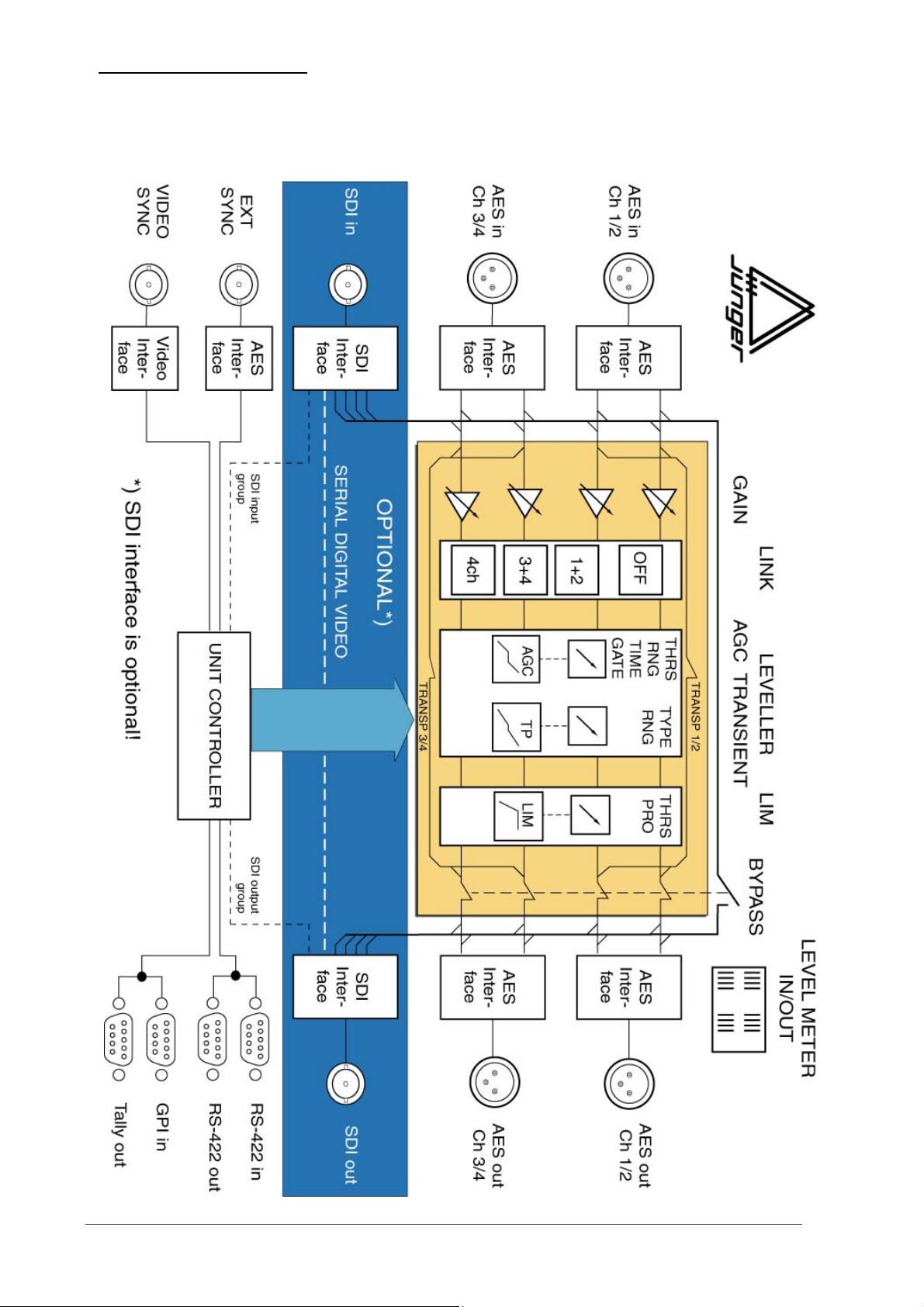
2.2
BLOCK DIAGRAM
page 2-2 operation manual b46, chapter 2 -Function description-
Page 9
2. FUNCTION DESCRIPTION
All signal processing is done in the digital domain by Texas
Instruments floating point signal processors. The use of 32 bit word
length for calculation ensures that there is no deterioration in signal
quality, even if an audio signal with a maximum word length of 24 bit is
input into the processing of the unit.
GAIN means linear amplification of input signals. The input gain can
be changed in steps of 0.1 dB , within a range from -15...+15 dB.
Adjustment of GAIN is channel independent.
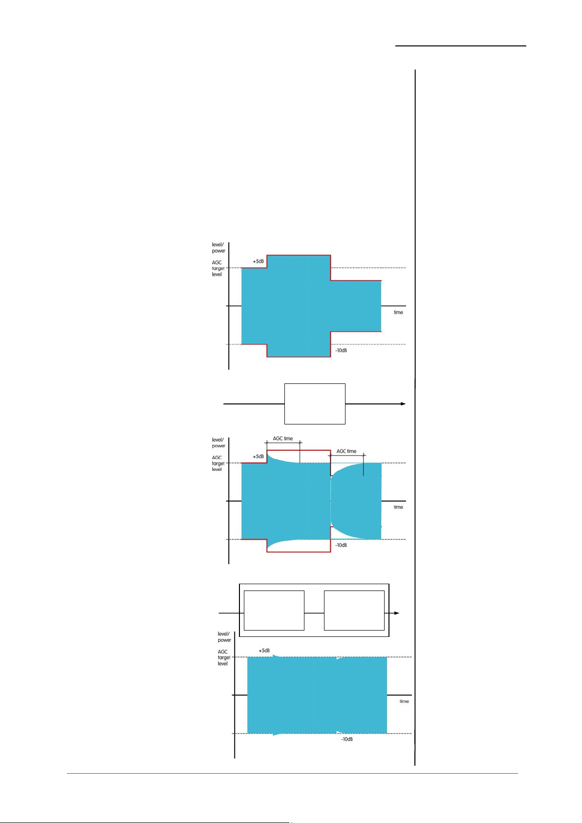
Level Magic ™ is a unique algorithm to make automated audio levelling
possible.
Input level change
Pic. 2 is showing a
theoretical level change
of +5dB and –5dB
around program level.
Working with AGC
In pic.3 a conventional
AGC is used to adjust
the level. As we can see
the AGC needs a certain
time to react, that is
necessary for mostly
inaudible gain correction.
But that’s too long to get
a proper correction of the
input level change.
Level Magic ™
Level Magic ™ is a
unique combination of a
transient processor and
an adaptive AGC
process. The transient
processor can fill the
lack of level control
against the slow acting
AGC. The total gain of
Level Magic ™ is the
addition of the gain by
the transient processor
and the gain of the AGC.
Transient
Processor
AGC
adaptive
AGC
2.3
AUDIO SIGNAL
PROCESSING
2.3.1
GAIN
2.3.2
AUDIO LEVELLER
LEVEL MAGIC ™
operation manual b46, chapter 2 -Function description- page 2-3
Page 10
2. FUNCTION DESCRIPTION
Adjustment
procedure
Process
description
Parameter
description
The Level Magic ™ process needs to be setup in three steps
- select one of the default presets for your apllication
(see preset description in chapter 5)
- adjust the operation level and peak level referring to
standards that are using for your application
- if the default preset is not giving satisfying results change
the parameters indivdually
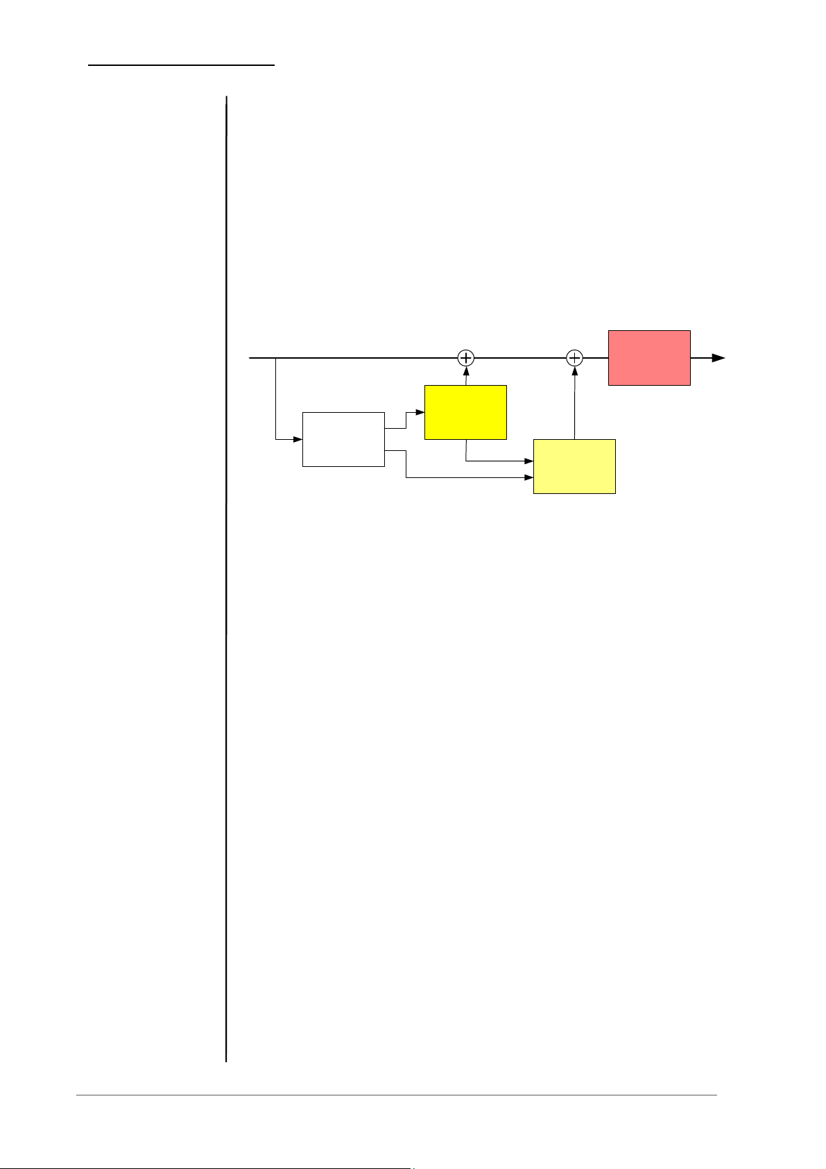
Level Magic ™ is using a unique combination of QP and RMS level
detectors to analyze the incoming audio signal. In comparing QP and
RMS measurement results we can find out how much transients are
coming in. Dependent on that the necessary resulting gain is controlled
in relation between transient processor and AGC.
Limiter
Transient
Processor
Level
Detection
AGC
Transient processor is doing fast gain change and the AGC is doing
slow gain change (depending on settings). The way how Level Magic is
acting on the audio is mostly determined by balancing between slow
and fast gain changing process. The AGC should be set in a way that
the gain change is mostly inaudible (1dB per 5 seconds or slower). The
Transient Processor should be set that incoming level jumps are
reduced but originally dynamic range is not changed too much. As
more possible gain by the Transient processor as more reduction of
the dynamic range is coming with.
SOFT level control: AGC range …15dB, time >=2min
Transient range …4dB, soft process
MID level control: AGC range …12dB, time >=1min
Transient range …6-8dB, mid process
HARD level control: AGC range …10dB, time >=40sec
Transient range …10dB, hard process
Parameter description:
AGC
OP-level operation level, target level for the AGC and for
the Transient Processor
Range max. gain by the AGC
Time time to reach the max. gain change
Gate threshold level that the AGC stops dynamic gain
change and is moving gain slowly to the long
term average gain change value
Transient Processor
Process a combination of level ratio and release
characteristic for the fast gain change (soft, mid,
hard)
Range max. gain by the Transient Processor
page 2-4 operation manual b46, chapter 2 -Function description-
Page 11
2. FUNCTION DESCRIPTION
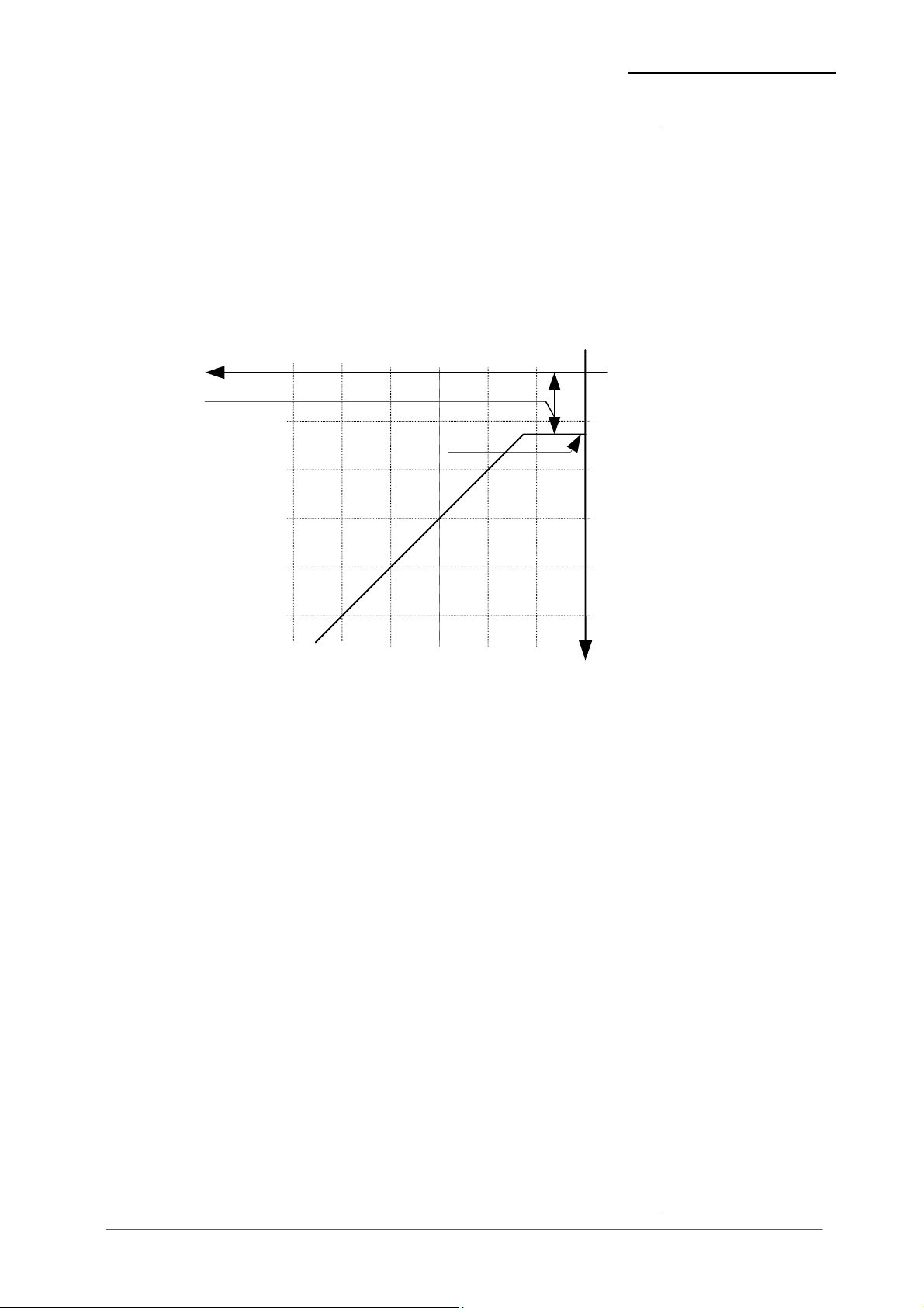
The static characteristics of the b46 limiter usually refers to a digital
output level of 0 dBFS (dB Full Scale). This is useful for most
applications of the dynamics processor as the on-following digital
recording system is supposed to be balanced down to the final bit.
For applications using headroom the output level of can be adjusted
within 0 ... -20 dBFS in steps of 0.1 dB. The limiter threshold
determines the maximum output level.
The static characteristics fo limiter (solid) at a limiter threshold of 12dBFS are illustrated in fig. 6
.
limiter
threshold
0...-20dBFS
input
-60
max. output
level
[dBFS]-10-20-30-40-50
-10
-20
2.3.3
LIMITER
fig. 6:
basic function:
limiter
-30
-40
-50
output
For the dynamics functions a signal delay of approx. 2 ms is built in.
This delay makes it possible to arrange the algorithm of the limiter in
such a way that the control mechanism is activated before maximum
level is reached (look ahead limiter). Within the rise time of the signal
the peak level is recognised and the maximum is calculated in such a
way that full scale level is reached precisely without causing clipping.
In case that the input signal (audio pair 1/2 or/and 3/4) is not audio (but
AC-3, Dolby E, MPEG..) the input can be feeded directly to the related
output bit transparent (no bit changes). The unit is switching to
transparent automatically if “non audio” flag in the Channel Status Bit
of the AES signal is set. Otherwise transparent mode can be set
manually by the user.
A change in the dynamic range of an audio signal is a non-linear
process. The gain of a dynamic range processor is not constant as it is
with the gain of a linear amplifier. The gain varies in time depending on
the input signal and depending on the specific control algorithm of the
dynamics processor. These variations in the gain, which represent the
real control process, should take place without any bothersome side
effects.
The dynamic range processor principle developed by Jünger Audio
makes it possible to realise dynamics processors (compressor, limiter,
expander) with very high audio quality, without signal discolouration,
pumping or breathing, without distortion and modulation products - in
2.3.4
TRANSPARENT
MODE
2.4
THE JÜNGER AUDIO
DYNAMICS
PROCESSOR
PRINCIPLE
operation manual b46, chapter 2 -Function description- page 2-5
Page 12
2. FUNCTION DESCRIPTION
short, with almost inaudible processing - and they are very easy to use.
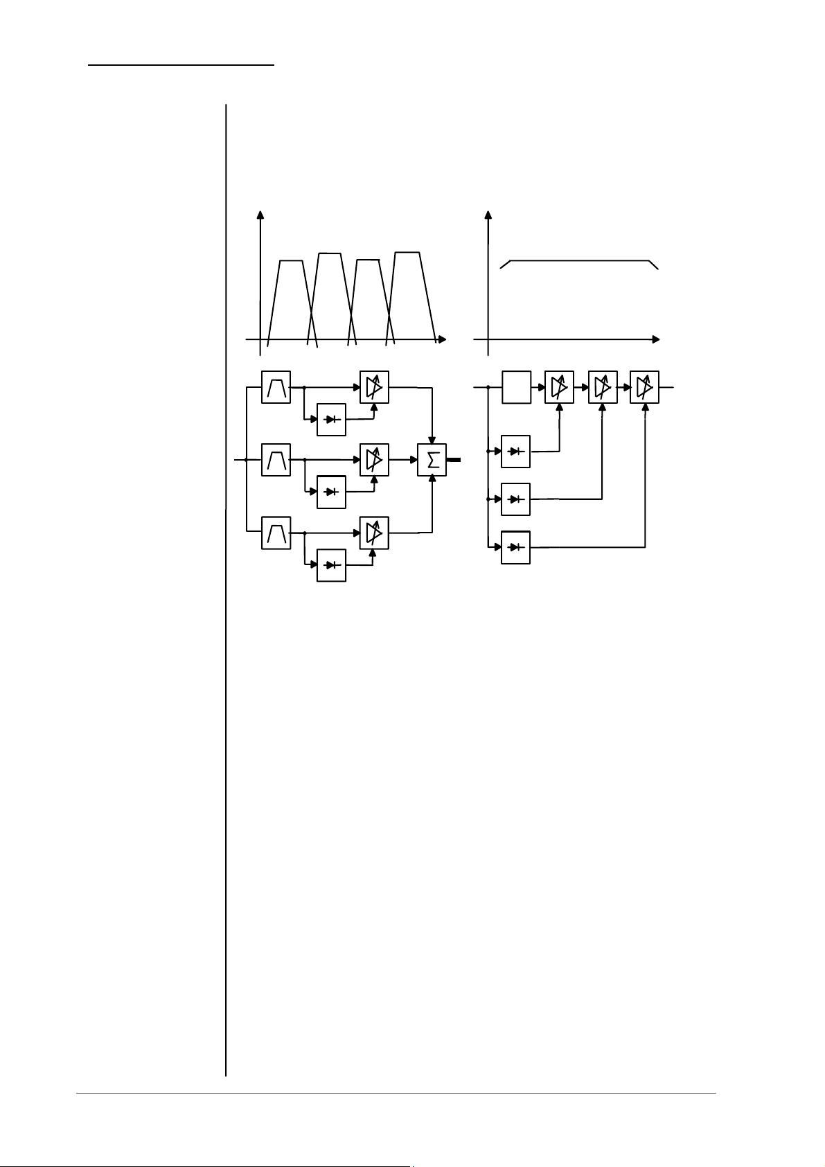
The Jünger Audio dynamics processors work according to a Multi-
loop principle, operating with an interaction between several
frequency linear control circuits. This is quite different to the popular
multiband structure which changes the sound.
A A
delay
1
1
2
n
Multi - Band
f
2
m
Multi - Loop
f
2.4.1
PROGRAM
The resulting attack and release times of the Multi-loop-system are
variable and adapted to the evolution of the input signal. This allows
relatively long attack times during steady-state signal conditions but
also very short attack times when there are impulsive input transients.
The Multi-loop structure also permits a short time delay between the
control circuit and the gain changing element. The gain control circuit
has time to preview the signal and become active before it reaches the
output. This is particularly important for the limiter, which provides a
precisely leveled output signal absolutely free of overshoots (clipping).
For some of the control parameter it is possible to define a limited
range of time constant values which is allowed for the adaptive
dynamic range algorithms. Inside this range the time constants can be
varied by the adaptive processing. Setting the range of time constant
values may be sometimes useful, to get the best signal processing
performance regarding specific programme material.
Parameter related to the transient response of the control circuit are
important for distortionfree processing. These time constants are
allways adaptive controlled without remarkable limitation of parameter
range. This is caused by the presence of transient pulses in allmost
each kind of programme material. The algorithm has to guarantee best
reaction for fast increasing level of transient signals anytime even if
classical music with slow dying out characteristic is processed. In all
page 2-6 operation manual b46, chapter 2 -Function description-
Page 13

2. FUNCTION DESCRIPTION
cases the attack time of the limiter for very short transients is zero.
Especially the release time of the control circuit has more influence to
the increase of loudness as any other parameter. The ranging of time
constants in processing time groups reflects this fact. The range for
processing time shows influence on release time parameter mostly.
The selection of the parameter PROGRAM changes the range of time
constant values as follows:
PRO processing time corresponds to
preset
--------------------------------------------------------------------------------------------- 0 2 ms to 0.2 sec
1 5 ms to 0.5 sec LIVE
2 10 ms to 0.8 sec
3 15 ms to 1.2 sec SPEECH
4 30 ms to 2.5 sec POP
5 50 ms to 3.5 sec
6 70 ms to 5.0 sec UNIVERSAL
7 100 ms to 6.0 sec
8 150 ms to 8.0 sec CLASSIC
9 250 ms to 10.0 sec
The audio signal delay through the dynamics processor is approx.
2ms due to delaying of the audio signal using internal memory. A
small delay is deliberately introduced to the audio signal in order to
allow limiter and compressor algorithms which can 'preview' the
audio signal before changing it. That is the signal curve can be
changed before maximum level is reached. This delay must be
considered before attempting to mix signals processed by the
dynamics processor with other undelayed signals.
When mixing together a delayed signal and a direct signal there may
be cancellation of the signal waveform at some frequencies and reinforcement of the waveform at other frequencies (comb filter effect).
Corresponding 2ms delay of direct signals should therefore be
carried out before mixing them with delayed processed signals.
2.4.2
INFLUENCE OF
SIGNAL DELAY
TIME
operation manual b46, chapter 2 -Function description- page 2-7
Page 14

Page 15

3. INSTALLATION
,
The digital audio level processor b46 can be remote-controlled
by means of parallel GPI contacts.
use : remote-controlled changeover of presets
connector: D-SUB 15pin, female
Pin assignments
Pin Signal name Logic I/O Functions
1 PRESET1 L I recall preset1
2 PRESET2
3 PRESET3
4 PRESET4
5 not used
6 BYPASS
7 Transp12
8 Transp34
9 SDI12
10 SDI34
11 not used
12 not used
13 not used
14 Common pin External voltage feed
15 +5V O Test power source
L
L
L
L
L
L
L
L
L
I recall preset2
I recall preset3
I recall preset4
I bypass on
I Input 1/2 transparent
I Input 3/4 transparent
I Input 1/2 on SDI
I Input 3/4 on SDI
Electrical specification:
GPI input potential free by opto-coupler, low active
OFF: +3.5…+30V between GPI input
and pin14
ON: less then 1.5V
min 50ms
Note: If using an external voltage feed it has to be connected to pin 14!
External Ground is switching the GPI on any of the inputs.
An internal voltage feed is available on pin 15. Ground is available from the
shield of the connector only! By using the internal voltage feed there is no
electrical isolation given anymore.
3.7
REMOTE
CONTROL
3.7.1
GPI REMOTE
CONTROL
(PARALLEL
REMOTE)
Pin14
Pin1...13
Ext. voltage
feed+3
Contact to
ext. Ground
5...30V
min. 50 ms
Operation manual b46, chapter 3 -installation- page 3-3
+3,5...30V
+1,5V
Page 16

Page 17

4. LOCATION OF PARTS AND CONTROLS
LOCATION OF PARTS AND
CONTROLS
sync / link
section
input
section
fig1: front panel b46
MODE selection/adjustment of sync, link
and SDI split mode
INPUT selection/adjustment of input and
SDI parameter (group selection)
LEVELLER selection/adjustment of leveller parameter
LIMITER selection/adjustment of limiter parameter
function
blocks
leveller
section
limiter
section
multi display/
edit section
CONTROL knob,
SELECT and EXIT
buttons
bypass
4
4.1.
FRONT PANEL
CONTROL
ELEMENTS
mains
switch
Operation manual b46, chapter 4 -location of parts and controls - page 4-1
Page 18

4. LOCATION OF PARTS AND CONTROLS
CONTROL knob selection (push) and adjustment (turn)
of processing parameter
SELECT/ selection of channels ( while editing process
ENTER parameters)
selection of utility menus
(ENTER) for recall and store of presets
ESC exit of adjustment menus and return to
level display
GAIN selection/adjustment of gain parameter
BYPASS switch for general bypass of the unit
page 4-2 Operation manual b46, chapter 4 -location of parts and controls -
Page 19

4. LOCATION OF PARTS AND CONTROLS
SDI IN-/
OUTPUT
DIGITAL
INPUTS
SERIAL
REMOTE
IN/OUT
GPI REMOTE
IN/OUT
SYNC IN
fig. 2: rear panel b46
POWER INPUT
IEC mains input connector 85-264V, 50/60 Hz with integrated fuse
REMOTE
serial remote interface RS-422
connector: 9pin SUB-D, input - female, output - male
GPI
parallel remote interface
TALLY-out open relais contact
connector: 15pin SUB-D, male
GPI-in +3,5…+30V potential-free
connector: 15pin SUB-D, female
SYNC
AES/EBU
connector: BNC socket
input for ext. sync signal (AES 3 format, 75 Ohm, unbal)
VIDEO input for video sync signal (blackburst, 75 Ohm, unbal)
connector: BNC socket
W-CLOCK output for wordclock sync signal, TTL level, unbal.
connector: BNC socket
SDI IN / OUT (only if installed!)
Input/output for serial digital video (ITU-R BT.601, SMPTE 272M-A)
with embedded audio
Format: 270 Mb/s, 525/625 line rate, 75 Ohm,
connector: BNC socket
DIGITAL IN
input for AES/EBU standard format
connector: XLR female panel jack
1- ground, 2-3 signal, balanced
connector: BNC socket 75 Ohm, unbalanced
DIGITAL OUT
output for AES/EBU standard format
connector: XLR male panel jack
1- ground, 2-3 signal, balanced , 4 Vpp
connector: BNC socket 75 Ohm, unbalanced, 0.5V pp
DIGITAL
OUTPUTS
4.2.
REAR PANEL
Operation manual b46, chapter 4 -location of parts and controls - page 4-3
Page 20

4. LOCATION OF PARTS AND CONTROLS
4.3
SWITCHES AND
JUMPERS FOR
CONFIGURATION
Some basic settings are to select by switches on the rear panel
or by switches and jumpers at the internal circuit boards of the
unit. These settings can occur general changes for operation
and should made by qualified engineering staff only.
Rear panel
Selection of the device address for serial
remote, 16 device addresses selectable
Note
device needs a different address! The selected
address is valid after next power-on reset of the unit.
Internal
To set any internal jumper or switches it is necessary to open
the unit.
PLEASE DO NOT MAKE ANY ALTERATIONS WITH THE
MAINS STILL CONNECTED TO THE UNIT!
Loosen the screws on the top cover and remove. Then you can
see all jumper and switches as shown in the drawing below.
After setting of jumper or switches reassemble the unit in
opposite order.
: Within a line of remote controlled units every
SDI
Interface
B4x
DSP card
page 4-4 Operation manual b46, chapter 4 -location of parts and controls -
J1
Download
J2
SDI Split
Main board
Page 21

4. LOCATION OF PARTS AND CONTROLS
The 4-channel processors of b40 series fitted with SDI-interface
are compatibel with the standard SMPTE 272M-AB. They
support 48 kHz synchronous audio sampling with 20 bit word
length.
The standard allows up to four groups each of four mono audio channels.
(Usually used by most of D-VTR's and other equipment is Group 1 with 48
kHz synchronous sampling.)
Group selection and other settings are to configure with settings
by front panel operation (mode section).
4.4
CONFIGURATION
OF SDI INTERFACE
Operation manual b46, chapter 4 -location of parts and controls - page 4-5
Page 22

Page 23

5. OPERATION
p
p
OPERATION
The use of the digital dynamics processor b46 is very easy.
The setup or the programming of the digital dynamics
processor b46 is made by adjustment of various parameters
and settings.
The description is made related to the functions in the menus.
5.1 adjustment of parameters
5.2 gain / loudness display
5.3 mode menu
5.4 input menu
5.5 leveller menu
5.6 limiter menu
5.7 utility menu
5.8 recall and storage of presets
5.9 editing of presets
5.10 list of factory presets
Following syntax is used:
SYMBOL ACTIVITY
describes
how to use
button or
rotary knob
ush
turn
ush + turn
describes
action or function of
button or
rotary knob
5
5.0
DESCRIPTION OF
OPERATIONS
operation manual b46, chapter 5 -Operation- page 5-1
Page 24

5. OPERATION
5.1
ADJUSTMENT OF
PARAMETERS
in all menus
5.2
GAIN /LOUDNESS
DISPLAY
After selection of one of the utility or function menus by
pushing any of the EDIT- buttons or the SELECT button one
can adjust displayed parameters.
CONTROL switches between parameter selection and
parameter adjustment mode, selected
push
CONTROL change of parameter selection or
adjustment of selected parameter value
(see menu explanation)
turn
parameter or value is highlighted by arrows
on display
Each time SELECT button is pushed it opens next utility menu.
If a function menu is opened (after pushing related EDIT
button) the SELECT button changes the channel selection.
After finishing of settings ESC button switches back to main
level display. All settings are stored as current adjustment
automatically.
The Loudness display becomes available if the loudness mode
is switched ON (see 5.5, 5th menu item). The loudness display
is showing short term loudness for the two channel pairs in
numerique value in LKFS units. In case there is no loudness
mode selected only the Gain display becomes available after
pushing the SELECT button.
Gain display shows gain setting for all channels. You can jump
to the gain menu from any other edit menu by pushing ESC
button. The character on the left hand side of the display
shows the selected loudness measurement method. “I” stays
for ITU.1770 mode.
Adjustments are made by turning&pushing CONTROL knob as
described previously (see 5.1).
I12 -24.0 I34 -27.0
O12 -23.0 O34 -29.0
Ixx: shortterm Loudness in LKFS of the input channel pair
Oxx: shortterm Loudness in LKFS of the output channel pair
GAIN 1: 0.0 3: 0.0
I >M:< 2: 0.0 4: 0.0
M: master control, ganging level settings for all channels
following channel 1
GAIN 1…4: channel independent -15.0 ... +15.0 dB
I: If the “I” shows up left hand of “M:” ITU weighting is
turned on (see 5.5 – leveller menu)
page 5-2 operation manual b46, chapter 5 -Operation-
Page 25

Mode menu shows sync setting and input selection.
Adjustments are made by pushing and turning CONTROL
knob (see 5.1). Return to level display with EXIT.
SYNC< LINK
AES 1 + 2 3 + 4
SYNC MODE: selection of sync signal input
CH 1/2 - sync on digital input 1/2
EXT - sync on external sync input
VIDEO - sync on video sync input
SDI - sync on SDI input
LINK MODE: all channels independent or following link
combinations:
1+2, 3+4, 1+2 & 3+4
Input menu shows input setting of the unit. There are two
windows available by pushing INPUT EDIT button once or
twice.
Adjustments are made by pushing and turning CONTROL knob
(see 5.1). Return to level display with EXIT.
1. menu
IN12< TR12 IN34 TR34
AES off SDI on
INxx: selection of signal input
AES digital input AES/EBU
SDI SDI input (embedded audio)
TRxx: selection of transparent input
on/off for bit transparent path between
auto input and output (for Dolby E)
If set to AUTO the path is switched to
transparent automatically if the
non-audio flag in the AES/EBU or SDI
signal is set.
2. menu (just if SDI interface is present)
SDI GROUPS: > IN< OUT
1 1
IN: selection of SDI group for deembedding
input signals 1...4
OUT: selection of SDI group for embedding
output signals 1...4
5. OPERATION
5.3
MODE MENU
5.4
INPUT MENU
operation manual b46, chapter 5 -Operation- page 5-3
Page 26

5. OPERATION
5.5
LEVELLER MENU
Leveller menu shows leveller settings for selected channel .
There are more windows available by pushing EDIT button
of LEVELLER section repeatedly.
Adjustments are made by pushing and turning CONTROL knob
(see 5.1). Return to level display with EXIT.
1. menu
PR CH >LVL< LDTARGET
01 2 ON -24.0
PR: number of current preset
CH: selected channel (change with SELECT)
LVL: leveller on/off
LDTARGET: loudness target in LKFS (if ITU BS.1770 is ON) or
operating level in dBFS (if ITU BS.1770 is OFF)
2. menu
PR CH >ZEROUP< ZERODN
01 2 +0dB -0dB
ZEROUP : Zero Zone treshold above loudness target
ZERODN: Zero Zone threshold below loudness target
3. menu PR CH >AGCMXGAIN< TIME
01 2 10dB 40s
AGCMXGAIN: max. gain by the AGC
TIME: AGC control time
4. menu PR CH
01 2 -50dBFS
FREEZE: freeze threshold level for the AGC in dBFS
5. menu PR CH >TPMXGAIN< RESP
01 2 10dB MID
TPMXGAIN: max. gain by the Transient Processor (TP)
RESP: TP response (slow, mid, hard)
page 5-4 operation manual b46, chapter 5 -Operation-
>FREEZE
Page 27

6. menu
PR >ITU BS.1770<
01 off
ITU BS.1770: Weighting of the leveller processing according
to ITU BS.1770. If turned on, the Loudness
Target becomes processing reference (instead
of Operating Level). By default the box is
changing Operating Level less 6dB to
determine Loudness Target (and vice versa).
All measurment definition by ITU (see BS.1770
document for details).
7. menu PROCESSING THR
-60
PROC THRESHOLD:
If the input signal is below this threshold all
remaining GAIN will be taken out.
If the input signal returnes above threshold
previous gain is applied again.
Pls. note this is not a PRESET parameter, but a global setting
for the box!
5. OPERATION
operation manual b46, chapter 5 -Operation- page 5-5
Page 28

5. OPERATION
5.6
LIMITER MENU
Limiter menu shows limiter settings for selected channel .
Adjustments are made by pushing and turning CONTROL knob
(see 5.1). Return to level display with EXIT.
PR CH >LIM< THRS PRO
01 2 ON -9.0 1
PR: number of current preset
CH: selected channel (change with SELECT)
LIM: limiter on/off
THRS: limiter threshold level -20 ... 0 dBFS
PRO: selected program-preset for adaptive
controlled algorithms
The selection of the parameter PRO in the limiter edit menu changes
the range of time constant values as follows:
PRO adaptive processing time corresponds to
preset
--------------------------------------------------------------------------------------------- 0 2 ms to 0.2 sec
1 5 ms to 0.5 sec LIVE
2 10 ms to 0.8 sec
3 15 ms to 1.2 sec SPEECH
4 30 ms to 2.5 sec POP
5 50 ms to 3.5 sec
6 70 ms to 5.0 sec UNIVERSAL
7 100 ms to 6.0 sec
8 150 ms to 8.0 sec CLASSIC
9 250 ms to 10.0 sec
The basic Multi-Loop principle of Jünger Audio dynamics processors
operates with adaption of dynamic range control parameters to the
incoming audio signal. That means permanently analysis and calculation
of attack times, release times , thresholds and interaction parameters of
several frequency linear control circuits.
(please refer to chapter 2 also)
Changing of PRO defines a limited range of time constant values which
is allowed for the adaptive dynamic range algorithms. Inside this range
the time constants can be varied by the adaptive processing. Setting the
range of time constant values may be sometimes useful, to get the best
signal processing performance regarding specific program material.
page 5-6 operation manual b46, chapter 5 -Operation-
Page 29

For opening and selection of UTILITY menus when
loudness/gain menu is on display.
push
gain display /
loudness display *
push ESC for close
utility menus and return
to loudness/gain display
push SELECT for open utility menus
Preset Load / Save / Edit
Brightness 1/2
Software version
LOCK
Push
SELECT for opening and selection of utitlity
menus
* loudness
display available
if loudness
mode is
switched ON!
ESC Reset to gain display, basic settings
are stored automatically
BRIGHTNESS1: display brightness when active (in use)
BRIGHTNESS2: display brightness when in display save
Mode (screen saver)
Software version C: controller firmware version
D: dsp firmware version
LOCK OFF/ON LOCK ON: all front pannel knobs are
locked, except the bypass-button
To enter into configuration you have to
enter the password (factory default 1234).
The password can be changed by choosing the
digit, pressing the knob, turniong the knob and
choose the wanted number and pressing the knob
again to confirm.
5. OPERATION
5.7
UTILITY MENU
operation manual b46, chapter 5 -Operation- page 5-7
Page 30

5. OPERATION
5.8
RECALL AND
STORAGE OF
PRESETS
5.9
EDITING OF
PRESETS
All individual settings for the function blocks can be stored as
presets. 10 presets are storable into the unit.
If the gain display is not visible push ESC button to switch back
to gain display.
SELECT selection of PRESET menu
push
CONTROL selection of LOAD or SAVE menu
turn
SELECT change to PRESET selection menu
push
CONTROL selection of preset number for loading or
saving preset
SELECT/ ENTER executes loading or saving of preset,
exit preset menu
Push any other button for leaving the preset menu without loading or saving
presets.
turn
push
5.10 shows some useful PRESETS that are already coming as
factory preset for applications with different audio formats:
All individual settings for the function blocks can be stored as
presets. 10 presets are storable into the unit.
These presets can be changed off-line, that means without
influencing running audio on the machine.
If the gain display is not visible push ESC button to switch back
to gain display and then:
SELECT selection of PRESET menu
push
CONTROL selection of EDIT menu
turn
SELECT change to PRESET selection menu
preset
SELECT/ ENTER executes editing of presets incl. gain
Setting. A blinking “E” in the display
shows that EDIT mode is valid.
push
CONTROL selection of preset number for editing
turn
push
page 5-8 operation manual b46, chapter 5 -Operation-
Page 31

If all changes are done push the ESC button to switch back to
gain display.
SELECT selection of SAVE or EXIT
+ CONTROL selection of preset number
Push
CONTROL
Select EXIT for leaving the EDIT menu without saving presets.
push
turn
selection of preset number
Push
5. OPERATION
operation manual b46, chapter 5 -Operation- page 5-9
Page 32

5. OPERATION
5.10
PRESET LIST
Parameter
MODE Sync
MODE Link
INPUT
In
INPUT
Transp
LEVELLER
LVL
LEVELLER
ITU.1770
LEVELLER
Loudness Target
LEVELLER
Zero Zone Up
LEVELLER
Zero Zone Down
LEVELLER
AGC Max Gain
LEVELLER
AGC Time
LEVELLER
Freeze Level
LEVELLER
Transient Proc
Max Gain
LEVELLER
Transient Proc
Response
LIMITER
LIM
LIMITER
Threshold
LIMITER
Program
Processing
Threshold
Range
1/ 2, EXT, Video SETUP -
4 schemes PRESET 1+2 & 3+4
AES/SDI*
for 1/2 and 3/4
ON/OFF/
AUTO
ON/OFF PRESET ON
ON/OFF PRESET ON
-40…0
LKFS
0…+6
dB
-6…0
dB
0…40
dB
1s…2h PRESET 40s
-60…-20
dBFS
0…15
dB
3 modes
soft, mid, hard
ON/OFF PRESET ON
0…-20.0
dBFS
5 modes
live, speech, uni, pop,
classic
-80…-40
dBFS
Setup/
Preset
SETUP/
GPI
SETUP/
GPI
PRESET -24
PRESET 0
PRESET 0
PRESET 10
PRESET -50
PRESET 10
PRESET Mid
PRESET -5
PRESET uni
SETUP -60
1…10
TV uni
-
-
page 5-10 operation manual b46, chapter 5 -Operation-
Page 33

6. BOOT DISPLAY AND TROUBLE SHOOTING
BOOT DISPLAY AND
T ROUBLE SHOOTING
display meaning / explanation
AUDIO LEVEL
PROCESSOR
C: x.x display of loaded controller software version
D: x.x display of loaded dsp software version
display error / message remedies
NO SYNC no sync at sync input! ! connect the sync input
NO SDI! SDI input selected, no
display of model
valid SDI signal
received!
(selectable in SYNC field) with
valid input signal
# CH 1/2: sync on DIGITAL IN
CH 1/2
# EXT: sync on SYNC
AES/EBU
# VIDEO: sync on SYNC
VIDEO
# SDI: sync on SDI input
! check the availability of SDI
data stream
or
! select another input
6
6.1
BOOT DISPLAY
6.2
ERROR
MESSAGES AND
TROUBLE
SHOOTING
Operation manual b46, chapter 6 -Boot display and trouble shooting- page 6-1
Page 34

6. BOOT DISPLAY AND TROUBLE SHOOTING
6.3
INITIALIZATION
THE UNIT
Should have remained the device no more operable and/or in the
program execution stand, recommends itself an initialization the
device.
During initialization, all storage areas important for the program
and registers are loaded with the factory setup and the program
is restarted.
Any button is to be held pressed in order to initialize the device
during switch-on of the device until the program started. To the
start of the program and at the completion of the displays (how
described in 7.1), the device is ready for operation with the
factory setup.
After an initialization of the device, all user presets and
adjustments are erased and/or overwritten by the factory
setup!
page 6-2 Operation manual b46, chapter 6 -Boot display and trouble shooting-
Page 35

7. APPLICATION NOTES
APPLICATION NOTES
In digital video recording technology four digital audio channels
are the standard configuration. This channel capacity is used
increasingly in production and post-production for surround
sound, providing mix options and for multi-lingual productions.
Quite often it is necessary to make corrections or changes to the
audio which until now required the use of an expensive digital
audio mixer. These tasks can now be easily solved with the
Jünger Audio range of digital audio toolboxes. Simple
processing for up to four digital audio signals may be carried out
quickly and efficiently.
Using the SDI versions (SDI=Serial Digital Interface, digital
component video format with 270Mb/s transmission) b40 series
can process embedded audio.
The standard allows up to four groups each of four mono audio
channels. Usually used by most of D-VTR's and other equipment
is Group 1 with 48 kHz synchronous sampling. Synchronous
means that the audio clock is genlocked to the associated video.
Each channel can have up to 20 bits of resolution per audio
sample.
The 4-channel processors of b40 series fitted with SDI-interface
are compatibel with the standard SMPTE 272M-A. They support
48 kHz synchronous audio sampling with 20 bit word length.
The Jünger Audio SDI interface provides for one group of four
audio channels to be extracted from or inserted into the SDI data
stream. To address a specific channel group the group selection
is possible (see 4).
The b46 provides an optional SD- or HD-SDI board. When you
switch on the device the plugged in interface will be indicated in
the display
FEATURES
• Bypass relay for SDI IN >SDI OUT
• Bit transparent for coded data streams (e.g. DOLBYE/20bit)
• De-embedder: user selectable de-embedding of one group
• Embedder: user selectable embedding to one of 4 groups
• SDI-SYNC: SDI input can be the clock source of the device
• For HD-SDI: Multi-Format HD/SD operation with auto
detection
7
7.1
B40 SERIES WITH
SDI-INTERFACE
(SD or HD available)
operation manual b46, chapter 7-Application notes- page 7-1
Page 36

7. APPLICATION NOTES
7.2
BASIC WORKING
MODES WITH SDI
For the basic working mode the input of the digital audio
processing can be selected between AES/EBU or SDI (serial
digital video with embedded audio). The processed signals are
present at both outputs always - at AES/EBU and SDI.
There are two additional working modes using the SDI interface.
SDI Bypass is bypassing the SDI data stream. In this case only
extracted audio is processed and available at AES output. In Split
Mode the audio path is splitted. Embedded audio can be
processed with external equipment via AES interface.
Following illustration shows working modes:
page 7-2 operation manual b46, chapter 7-Application notes-
Page 37

8. TECHNICAL SPECIFICATIONS
TECHNICAL
SPECIFICATIONS
sample rate : 48 kHz
audio data format : 24 bit (AES/EBU), 20 bit (SDI)
DIGITAL IN/OUT
AES/EBU
connector : XLR,110 Ohm, balanced
BNC, 75 Ohm, coaxial
input format : AES professional, AES consumer
output format : same as input format
SDI (only for SDI version)
SD-SDI
VIDEO :
standard: SMPTE 272 M–A, 270 Mbit SD-SDI
connection: BNC, 75 Ohm, coaxial
signal level: 800mV ±10%
equalisation: 300m (Belden 8281 , 270 MHz)
return loss: >15 dB
supported video standards:
SD 525/59.94 SMPTE 125M
SD 625/50 SMPTE 125M
AUDIO :
audio data format : 20 Bit, transparent for C-Bit and U-Bit according to
AES3
audio sample rate : 48 kHz synchronous to video-carrier
latency : (deembedder + embedder)
SD : < 2,6 msec
GENERAL :
power supply : +5V DC
consumption : approx. 500 mA
dimension : 3RU, 4HP, 160mm depth (EUROPA size pcb)
temperature : 10°C to 40°C
humidity : 90%, non condensing
digital signal
8
processing
digital
in- / outputs
SDI
in- / outputs
(optional)
operation manual b46, chapter 8-Technical specifications- page 8-1
Page 38

8. TECHNICAL SPECIFICATIONS
sync
in- / outputs
HD-SDI
technical specifications
VIDEO :
standard: SMPTE 299M 1,485 Gbit HD-SDI
SMPTE 272M–A, C 270 Mbit SD-SDI
connection: BNC, 75 Ohm, coaxial
signal level: 800mV ±10%
equalisation: 130m (Belden 1694A, 1.485GHz)
300m (Belden 8281 , 270 MHz)
return loss: >15 dB (1.485 GHz)
supported video standards:
HD 720/60 SMPTE 296M HD 1080/25 SMPTE 274M
HD 720/50 SMPTE 296M HD 1080/24 SMPTE 274M
HD 720/30 SMPTE 296M HD 1080/50 SMPTE 295M
HD 720/25 SMPTE 296M HD 1035/60 SMPTE 260M
HD 720/24 SMPTE 296M
HD 1080/60 SMPTE 274M SD 525/59.94 SMPTE 125M
HD 1080/50 SMPTE 274M SD 625/50 SMPTE 125M
HD 1080/30 SMPTE 274M
all HD-standards are supported also with their 1/1001-frame-rates
AUDIO :
audio data format : 24 Bit, transparent for C-Bit and U-Bit according to
AES3
audio sample rate : 48 kHz synchronous to video-carrier (SD and HD)
32 kHz ... 48 kHz asynchronous to video-carrier (HD
only)
latency : (deembedder + embedder)
HD : < 800µsec
SD : < 2,6 msec
GENERAL :
power supply : +5V DC
consumption : approx. 1.000 mA
dimension : 3RU, 4HP, 160mm depth (EUROPA size pcb)
temperature : 10°C to 40°C
humidity: 90%, non condensing
SYNC IN
AES/EBU
connector : BNC, 75 Ohm, coaxial
level : 0,5 ... 5 Vpp
input format : AES professional, AES consumer
VIDEO
connector : BNC, 75 Ohm, coaxial
level : 0,5...1 Vpp
input format : Blackburst or PAL/NTSC composite video
page 8-2 operation manual b46, chapter 8-Technical specifications-
Page 39

REMOTE
serial remote interface RS-422 in/out
level : TTL
connector : 9 pin SUB-D male/female
GPI parallel remote
level : +3…+30V, H-active, optocoupler
connector : 15 pin SUB-D female
Tally Out level : normally closed relais contacts
Contact rating: 1A 24 VDC, 0,5 A 125 VAC
max. 30 W 62,5 VA
max. 60 VDC, 125 VAC
connector : 15 pin SUB-D male
GENERAL
power consumption : appr. 15 VA
dimensions : 19“, 1 RU, 250 mm depth
weight : appr. 5 kg
8. TECHNICAL SPECIFICATIONS
remote control
operation manual b46, chapter 8-Technical specifications- page 8-3
Page 40

9. WARRANTY AND SERVICE INFORMATION
9
WARRANTY AND SERVICE
INFORMATION
JÜNGER AUDIO grants a two-year warranty on the
4-channel digital audio leveller b46
If the unit has to be serviced, please send it, ideally in the
original box, to:
JÜNGER AUDIO - Studiotechnik GmbH
Justus-von-Liebig-Str. 7
D - 12489 Berlin
GERMANY
Tel.: (*49) -30-677721-0
Fax.: (*49) -30-677721-46
operation manual b46, chapter 9 -Warranty and service information- page 9-1
Page 41

KONFORMITÄTSERKLÄRUNG
DECLARATION OF CONFORMITY
Geräteart: Digitaler Dynamikprozessor
Type of equipment: digital dynamics processor
Produkt / Product: b46
Das bezeichnete Produkt stimmt mit den Vorschriften folgender EU-Richtlinie(n) überein:
The aforementioned product complies with the following Europaen Council Directive(s):
89/336/EWG (geändert durch 91/263/EWG und 92/31/EWG)
(changed by 91/263/EWG and 92/31/EWG)
Richtlinie der Rates zur Angleichung der Rechtsvorschriften der
Mitgliedsstaaten über die elektromagnetische Verträglichkeit
Council Directive 89/336/EC on the approximation of the laws of the
Member States relating to electromagnetic compatibility
Zur vollständigen Einhaltung dieser Richtlinie(n) wurden folgende Normen herangezogen:
To fully comply with this(these) Directive(s), the following standards have been used:
EN 55022 :1987
EN 50082-1 :1993
Dieser Erklärung liegt zugrunde: Prüfbericht(e) des EMV-Prüflabors
This certification is based on: Test report(s) generated by EMC-test laboratory
MEB Messelektronik Berlin Kalibrier- und Prüflabor
accredited EMC laboratory
Aussteller / Holder of certificate: Jünger Audio Studiotechnik GmbH
Justus-von-Liebig-Strasse 7
D - 12489 Berlin
Berlin, 18.03.2003 ........................................................
(Ort/Place) (Datum/Date) (Rechtsgültige Unterschrift / Legal Binding)
CE Konformitätserklärung d06 Jünger Audio Studiotechnik GmbH, Berlin November 2004
Page 42

Page 43

Page 44

JÜNGER AUDIO - Studiotechnik GmbH
Justus-von-Liebig-Str. 7, D - 12489 Berlin, GERMANY
Tel.: +49 30 6777210, Fax.: +49 30 67772146
www.junger-audio.com
 Loading...