

Page 1
4ch digital audio delay
b45
release 3.0
Page 2

Page 3

FOREWORD
Thank you for buying and for using the 4-channel Digital Audio
Delay B45.
Not only you have aquired the latest generation of digital
dynamic range processing, but also a piece of equipment
which is unique in its design and specification.
Please read this manual carefully to ensure you have all the
information you need to use the 4-channel Digital
B45.
The unit was manufactured to the highest industrial standards
and went through extensive quality control checks before it
was supplied.
If you have any comments or questions about installing,
setting-up or using the b45, please do not hesitate to contact
us.
Audio Delay
0
The information contained in this manual is subject to change without notice.
This manual is the copyright of Jünger Audio. All reproduction and copying, other than for legal
owner’s personal use, or disclosure of part or whole to a third party, is not allowed without prior
written authorization by Jünger Audio. © Jünger Audio, Berlin 2004
Page 4

1
2. Function description ...........................................…….............
2.1 Basic description ...........................................…….................
2.2 Block diagram ..............................................…….................
2.3 Remote system ...............................................................…..
2.4 Link function / channel configuration .........................…........
2.5 Display of delay time .......................................................…..
2.6 Video format ....................................................................…..
2.7 Auto tracking .................................................................... …
2.7.1 Auto tracking by video sync ...............................……....
2.7.2 Auto tracking by TTL control signal ........................……
2.7.3 Auto tracking with offset ..........................................……
3. Installation ............................................................................
3.1 Unpack the unit ..............................................…...............
3.2 Power supply ...................................................…...............
3.3 Connections .....................................................…...............
3.4 Rack mounting ................................................…................
3.5 Operation safety ..............................................…..............
3.6 Synchronization of digital output ......................................
3.7 Remote Control ............................................….................
3.7.1. GPI Remote Control ......................................……..........
3.7.2. Tally Out ......................................................……............
3.7.3. Serial Remote Control .................................……............
4. Location of parts and controls ........................…....................
4.1 Front panel .......................................................……..............
4.2 Rear panel ........................................................…….............
4.3 Switches and jumpers for configuration ...........……..............
4.4 Selection of Auto Tracking mode ......................................
4.5 Selection of SDI Split Mode ..............................…….............
4.6 Selection of SDI audio group ...........................……..............
CONTENTS
2-1
2-1
2-2
2-3
2-4
2-4
2-4
2-5
2-5
2-6
2-6
3-1
3-1
3-1
3-1
3-1
3-1
3-2
3-3
3-3
3-4
3-5
4-1
4-1
4-2
4-3
4-4
4-4
4-5
Page 5

5. Setup ..............................................……..............……………....
5.0 Description of setup operation ...........................................
5.1 Starting and selection of edit menus ..................................
5.2 Main display .......................................................................
5.3 Adjustment of delay time setup parameters .......................
5.4 Storage of presets .............................................................
5.5 Menu overview ..................................................................
6. Operation ............................………….......................................
6.0 Description of operation .....................................................
6.1 Working with presets .........................................................
6.2 Recall of presets ................................................................
6.3 Adjustment of delay time ...................................................
7. Boot display and trouble shooting ............................................
7.1 Boot display .......................................................................
7.2 Error messages and trouble shooting ................................
7.3 Initialization the unit ............................................................
8. Technical specifications ...........................................................
9. Warranty and service information ...........................................
5-1
5-1
5-2
5-2
5-3
5-3
5-4
6-1
6-1
6-2
6-2
6-2
7-1
7-1
7-1
7-2
8-1
9-1
Page 6

Page 7

2. FUNCTION DESCRIPTION
FUNCTION DESCRIPTION
The programmable digital audio delay b45 is a professional
studio device for delaying of 4 digital audio channels.
Digital audio delay b45 is working with a new processing
algorithm developed by Jünger Audio. It is possible to change
the delay time "glitch free" - without changing of pitch, without
noises or clicks. Readjustment of audio delay time under live
conditions - inaudible and fast done with the digital audio delay
b45!
The four channel configuration matches the audio capability of
Digital VTR's. B45 can be used as remotable and programmable
audio delay in digital video systems.
The unit is programmable,easy to operate and requires only a
limited number of settings for fast and efficient audio processing.
• 4 channel programmable digital audio delay
• "glitch free" changing of delay times
• auto tracking function
• up to 1,2 s delay time per channel
• user friendly preset and recall system
• external sync mode, AES/EBU or VIDEO
• RS-422 interface for serial remote
• GPI interface for parallel remote control input, tally output
2
2.1
BASIC
DESCRIPTION
operation manual b45, chapter 2 -Function description- page 2-1
Page 8
2. FUNCTION DESCRIPTION
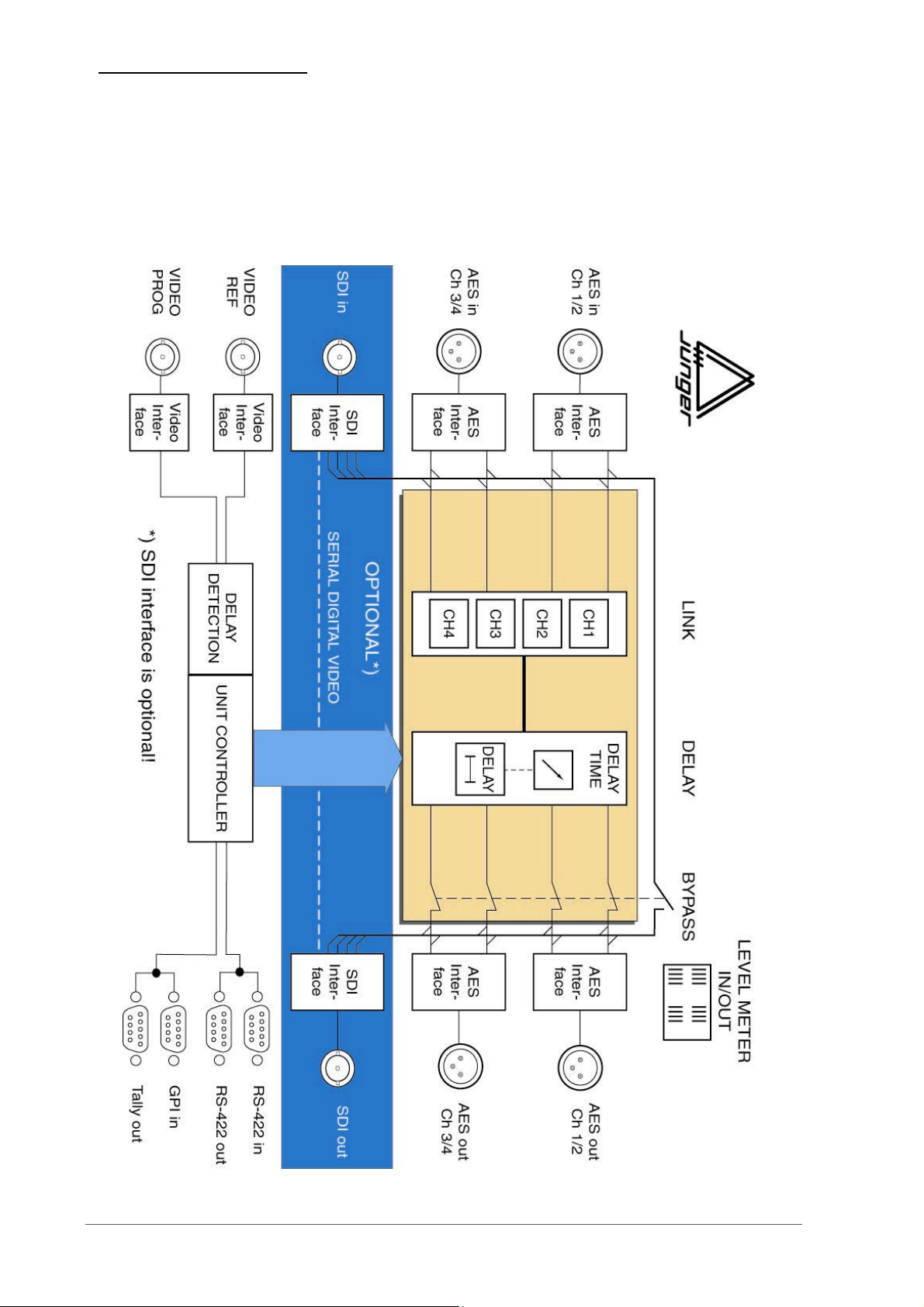
2.2
BLOCK DIAGRAM
page 2-2 operation manual b45, chapter 2 -Function description-
Page 9
2. FUNCTION DESCRIPTION
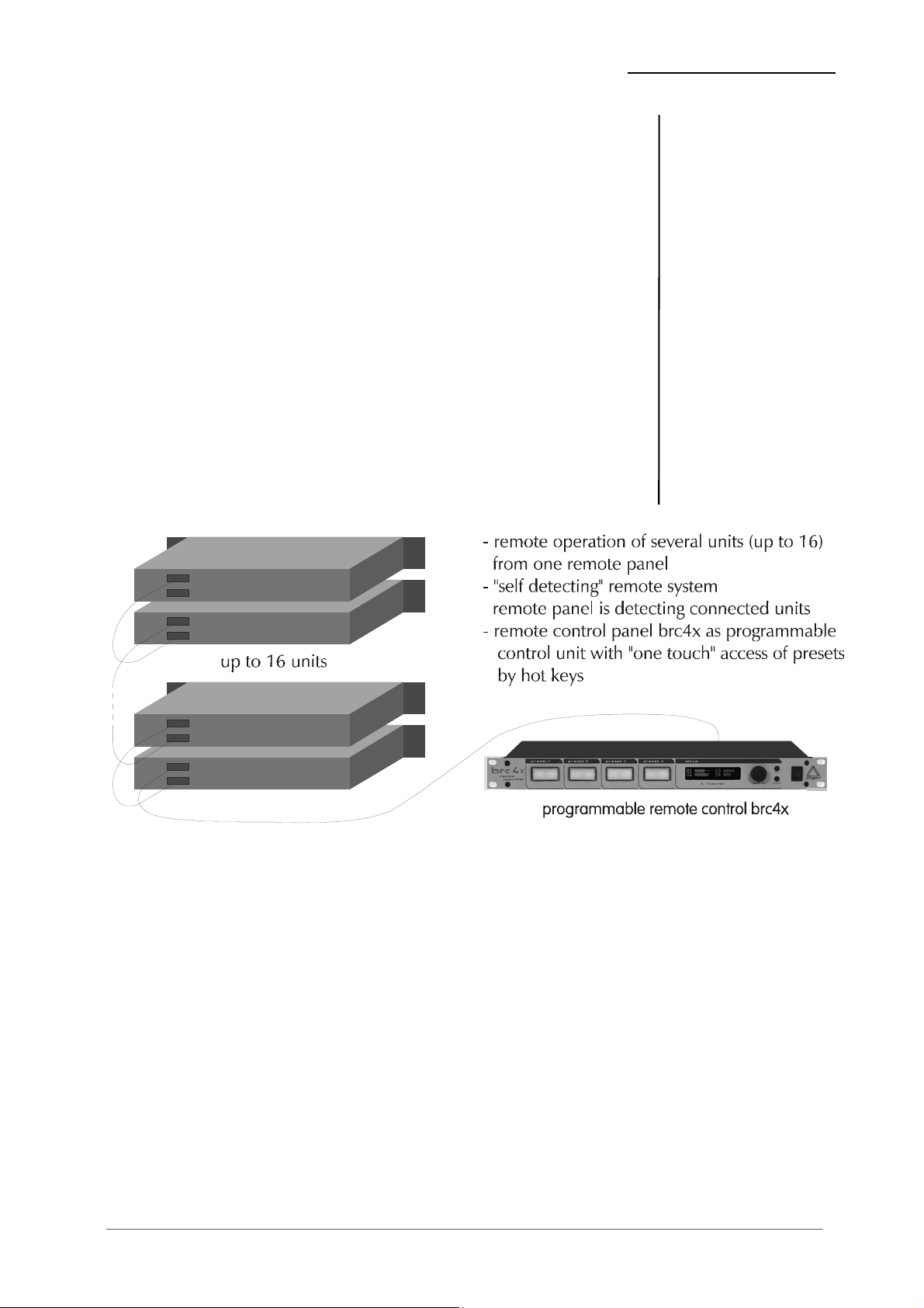
The digital audio delay b45 is fitted with an serial remote
interface in RS-422 format.
Every device needs a device address to be registered in a
remote system. The address can be selected with the ADDR
switch on the rear panel. 16 addresses are selectable (0..F).
The preselected address is valid with next power-on reset.
Up to 16 delays b45 can be controlled from one remote panel
brc4x.
Device model name and device address are to recognize using
the remote protocol of serial remote interface by an automation
system or by PC. With it various boxes can be combined in one
remote system or remote chain. However a maximum of 16
devices per model can be controlled in one chain.
2.3
REMOTE SYSTEM
operation manual b45, chapter 2 -Function description- page 2-3
Page 10

2. FUNCTION DESCRIPTION
2.4
LINK FUNCTION /
CHANNEL
CONFIGURATION
2.5
DISPLAY OF DELAY
TIME
2.6
VIDEO FORMAT
The LINK function is used for channel configuration regarding
delay time adjustment. It eables convenient setting of delay time
for a group of audio channels. Following links or channel
configuration are possiblel:
CH1 + CH2 + CH3 + CH4 (all 4 channels linked)
CH1 + CH2 CH3 + CH4 (two linked pairs)
CH1 CH2 CH3 CH4 (all channel independent)
The LINK function is a basic setting and is valid for all presets.
All linked channels are working with the same delay time.
Adjustment of delay time is valid for linked channels at the same
time.
The display is showing delay time for all four presets (not more
for individual channels) if all four channels are linked (P1 ...P4).
The adjusted delay time can be displayed in various time scale
formats. The time scale format is to select in DELAY menu. The
resolution for the adjustment is changing with selection of
specific time scale format. For some formats (f.i. frames)
adjustment is possible in larger steps only.
Time scale format can be different for different presets. Time
scale format will be stored by storing adjustments into the preset.
To get the right delay time (as absolut time value) it is necessary
to set the correct video format (PAL/NTSC). The video format is
to select in setup menu.
If the unit is synchronized to video reference the selection of
video format is done automatically independent of the video
format selection in setup menu.
page 2-4 operation manual b45, chapter 2 -Function description-
Page 11
2. FUNCTION DESCRIPTION
The digital audio delay b45 can be used in Auto Tracking Mode.
Auto Tracking means the control of current delay time by specific
generated control signal. Together with the „glitch free“ changing
of delay time Auto Tracking works without any noises or
detoriation in the audio signal.
The control signal for auto tracking can be generated in different
ways. Depending on the generation of the control signal it is
causing a different maximum length of auto tracking delay time.
There are two basic methods to generate the control signal. First
one is the comparison of two video signals. The video program
signal (VIDEO TRACKING) will be compared with video
reference (VIDEO SYNC). Difference in time between both
vertical intervals is used as auto tracking delay time. Second way
is to use a TTL signal. The length in time of the pulse signal is
measured and will be used as current delay time.
Selection of auto tracking mode is done by setting jumper J2 on
tracking board (see also 4.4).
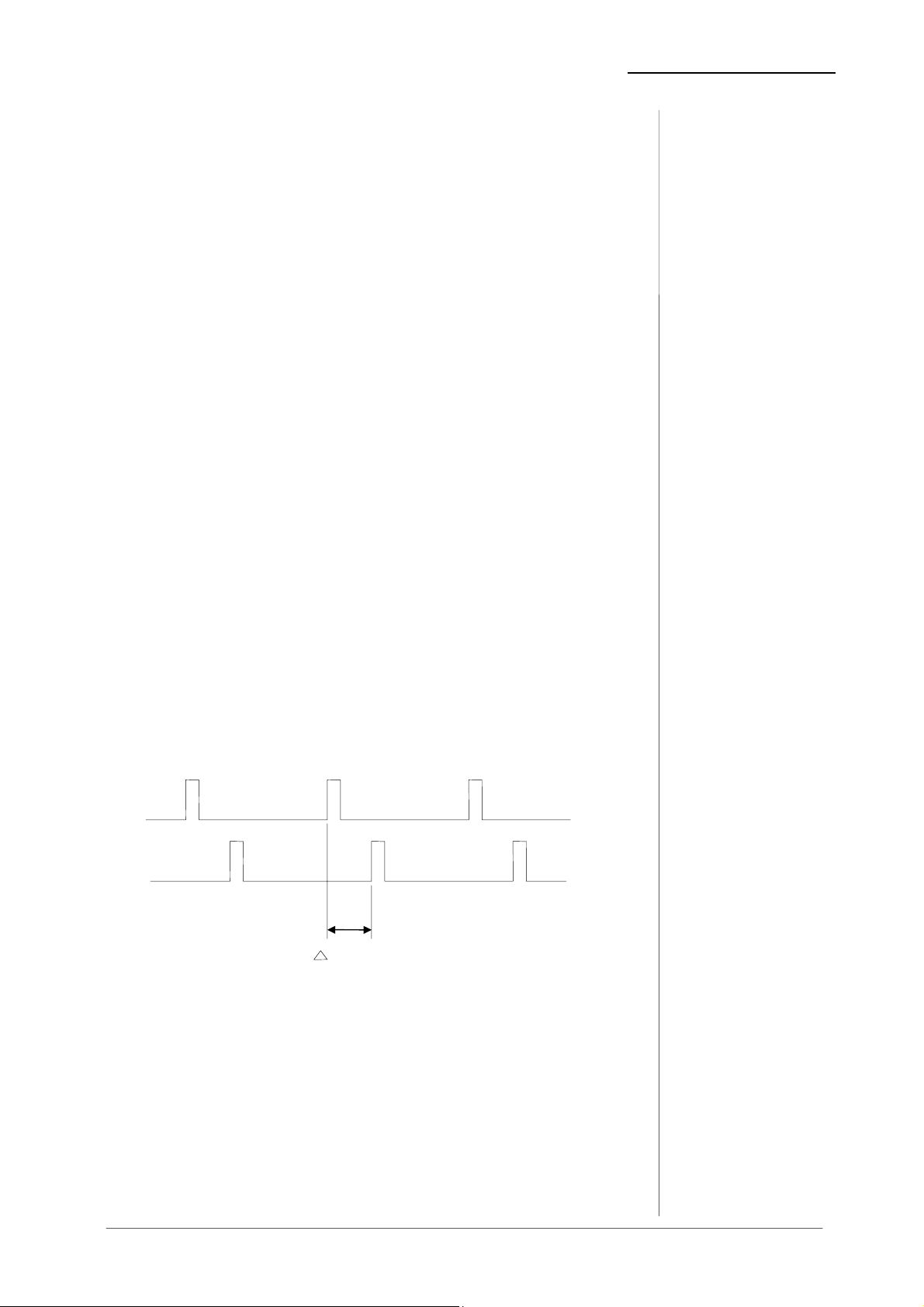
The digital audio delay b45 can generate the auto tracking
control signal by comparison of two video signals. To calculate
the auto tracking delay time the algorithm compares the video
program signal (VIDEO TRACKING) with video reference
(VIDEO SYNC). The difference in time between both vertical
intervals is used as auto tracking delay time. The maximum
difference and in this way the maximum delay time is one video
frame (PAL = 40 ms).
VIDEO
SYNC
VIDEO
TRACKING
t = t
t
vt
- tracking delay time
vt
2.7
AUTO TRACKING
2.7.1
AUTO TRACKING BY
VIDEO SYNC
operation manual b45, chapter 2 -Function description- page 2-5
Page 12
2. FUNCTION DESCRIPTION
2.7.2
AUTO TRACKING
BY TTL CONTROL
SIGNAL
2.7.3
AUTO TRACKING
WITH OFFSET
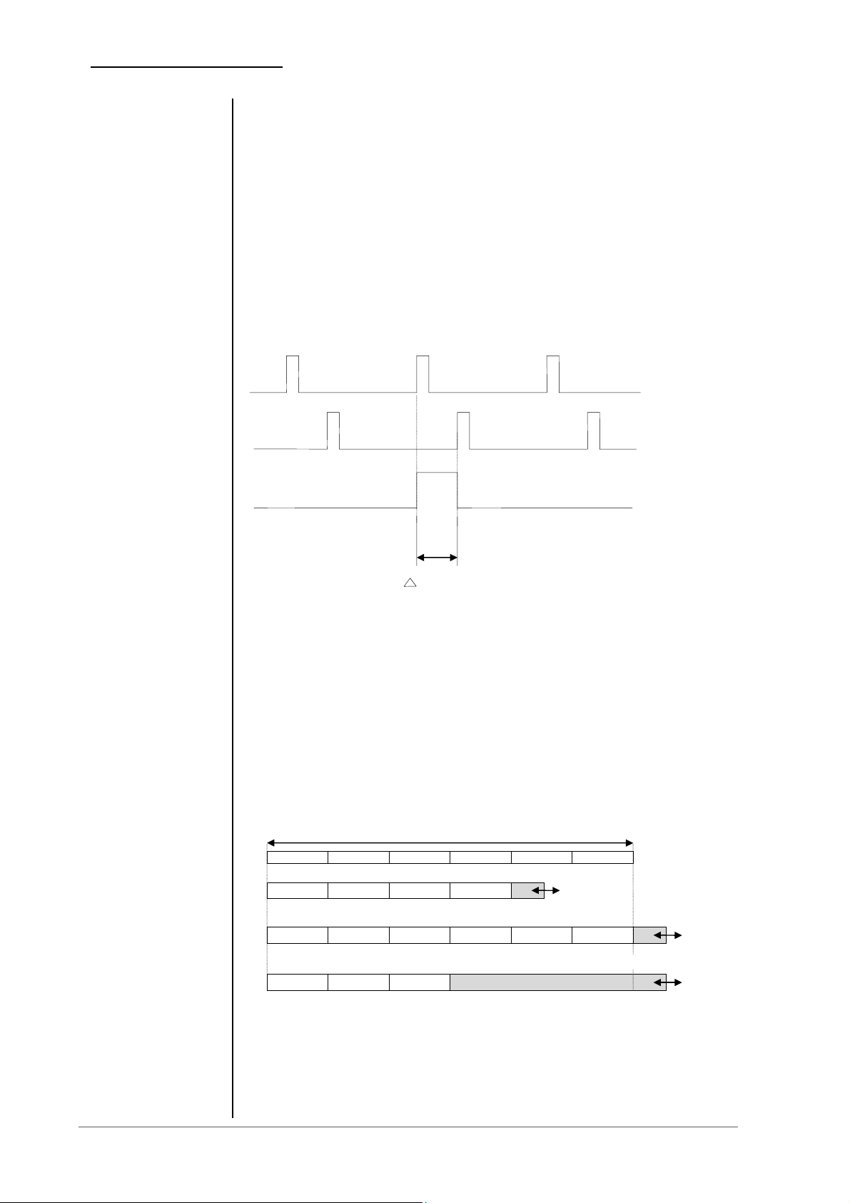
The digital audio delay b45 can generate the auto tracking
control signal by using a TTL control signal. To calculate the auto
tracking delay time the detection circuit is measuring the HIGH
period of the TTL input signal. The length in time of the HIGH
period is used as delay time for auto tracking. The maximum
delay time shouldn’t be more as the maximum memory capacity
of the delay (see technical specifications). Otherwise it produces
a memory overflow and an error message will be displayed.
Every new positive pulse at TTL input is measured and is
overwriting the last calculated value.
VIDEO
SYNC
VIDEO
TRACKING
TTL PULSE
t
t = t
vt
- tracking delay time
vt
There is the possibility to activate auto tracking even if a fixed
delay time is preadjusted. The already adjusted delay time is an
offset to the auto tracking delay time. Please note that the overall
delay time consisting of delay offset and auto tracking delay time
shouldn’t be more as the maximum memory capacity of the
delay (see technical specifications). Otherwise it produces a
memory overflow and an error message will be displayed. The
use of the unit is blocked to prevent deteriorated audio signals at
digital output.
t
= maximum memory capacity per channel
vmax
auto tracking video with offset
auto tracking video with offset, error message overflow
auto tracking TTL with offset, error message overflow
Note! In auto tracking TTL auto tracking delay time can be
longer as one videoframe!
page 2-6 operation manual b45, chapter 2 -Function description-
Page 13

3. INSTALLATION
INSTALLATION
The digital audio delay b45 was carefully packed in the factory
and the packaging was designed to protect the equipment from
rough handling. Please examine carefully the packaging and its
contents for any signs of physical damage, which may have
occured in transit.
The digital audio delay b45 is a device under the safety category
Schutzklasse 1 in keeping with the VDE 0804 standards and
may only used with power supply installations built according to
regulations.
Check the voltage details printed at the rear panel are the same
as your local mains electricity supply.
The digital audio delay b45 is equipped with standard connectors
(see also chapter 3).
Before connecting the digital audio delay b45 switch the power
off at all connected units.
The digital audio delay b45 is made as standard 19“ unit (EIA
format). It occupies 1 RU (44 mm height) space in a rack.
Please allow at least addititonal 3“ depth for the connectors on
the rear panel.
When installing the unit in a 19“ rack the rear side of the unit
needs some support, especially for mounting in flight cases.
The digital audio delay b45 should not be installed near units
which produce strong magnetic fields or extreme heat. Do not
install the filter processor directly above or below power
amplifiers.
If, during operation, the sound is interrupted or displays no longer
illuminate, or if abnormal odor or smoke is detected immediately
disconnect the power cord plug and contact your dealer or
Jünger Audio.
3
3.1
UNPACK THE UNIT
3.2
POWER SUPPLY
3.3
CONNECTIONS
3.4
RACK MOUNTING
3.5
OPERATION
SAFETY
Operation manual b45 chapter 3 -installation- page 3-1
Page 14

3. INSTALLATION
3.6
SYNCHRONIZATION
OF
DIGITAL OUTPUT
The digital audio delay b45 has a digital signal output only. To
the problem-free combination of following digital devices, the
digital signal processing can be locked to an external clock
reference. The selection of the corresponding input is made in
the SYNC MODE menu. If the chosen sync input is connected
with the sync signal, this signal is used for synchronization
automatically. The digital output signal can be clocked with the
following clock frequencies:
CH 1/2 locks with the clock frequency of the input signal at
digital input CH 1/2 (AES/EBU, 48 kHz)
EXT SYNC locks with the clock frequency at the
external sync input (AES/EBU, 48 kHz)
VIDEO locks with the clock at the Video sync input
(internal 48 kHz)
SDI VIDEO locks with the clock at the SDI input
(internal 48 kHz)
Both digital outputs CH 1/2 and CH 3/4 are locked with same
clock frequency.
Note: SDI sync is available only if SDI input is active!
page 3-2 Operation manual b45, chapter 3 -installation-
Page 15

3. INSTALLATION
The Digital audio delay b45 can be remote-controlled by means
of parallel GPI contacts.
use : remote-controlled changeover of presets
connector: D-SUB 9pin, female
Pin assignments
5 1
Pin Signal name Logic I/O Functions
1 PRESET1 L I call preset1
2 PRESET2 L I call preset2
3 PRESET3 L I call preset3
4 PRESET4 L I call preset4
5 not used
6 BYPASS L I bypass on
7 not used
8 not used
9 GROUND Ground
9 6
Electrical specification:
GPI input On: connection to ground
Off: open
signal input level L: 1,5V or less, min. 50ms
level H: 3,5V or more
+3,5V
3.7
REMOTE
CONTROL
3.7.1
GPI REMOTE
CONTROL
(PARALLEL
REMOTE)
min. 50 ms
+1,5V
Operation manual b45 chapter 3 -installation- page 3-3
Page 16

3. INSTALLATION
3.7.2
TALLY OUT
The Digital audio delay b45 can signal specific device statuses
via parallel Tally lines.
use
: Control of the remote-controlled changeover of
presets
connector: D-SUB 9pin, male
Pin assignments
5 1
Pin Signal name Logic I/O Functions
1 PRESET1 H O preset1 recalled
2 PRESET2 H O preset2 recalled
3 PRESET3 H O preset3 recalled
4 PRESET4 H O preset4 recalled
5 LIMITER H O limiter on
6 BYPASS H O bypass on
7 SYNC ch1/2 H O input 1/2 locked
8 SYNC ch3/4 H O input 3/4 locked
9 GND Ground
9 6
Electrical specification:
signal input level L: 1,5V or less
level H: 3,5V or more
+5 V
page 3-4 Operation manual b45, chapter 3 -installation-
110 Ohm
TALLY OUT
max. 25 mA
Page 17

The Digital audio delay b45 can be remote-controlled by means
of serial remote RS-422.
use
: remote-controlled changeover of presets
protocol: available on request
connector: D-SUB 9pin, input - male
output - female
Pin assignments
The cable is wired 1:1 completely, the shield of the cable must be connected
on both ends!
5 1
3. INSTALLATION
3.7.3
SERIAL REMOTE
CONTROL
(RS-422)
REMOTE IN
Pin Signal name Functions
1 DSR + out Data set ready
2 DSR - out
3 SENSE in Interrogation Remote
4 RXD + out Receive data
5 RXD - out
6 DTR + in Data terminal ready
7 DTR - in
8 TXD + in Transmit data
9 TXD - in
REMOTE OUT
Pin Signal name Functions
1 DSR + in Data set ready
2 DSR - in
3 GND GND
4 RXD + in Receive data
5 RXD - in
6 DTR + out Data terminal ready
7 DTR - out
8 TXD + out Transmit data
9 TXD - out
9 6
Electrical specification:
signal in-/outputs TTL-level
Operation manual b45 chapter 3 -installation- page 3-5
Page 18

Page 19

4. LOCATION OF PARTS AND CONTROLS
LOCATION OF PARTS AND
CONTROLS
All control elements give direct access.
In menu modes the LCD-panel shows specific functions.
preset
buttons
setup
section
4
4.1.
FRONT PANEL
Adjustment knob,
fig1: front panel b45
PRESET 1...4 selection of presets 1...4
CONTROL selection (push) and adjustment (turn)
of parameters
SELECT selection of menus (for adjustment of
parameters)
EXIT exit of adjustment menus and return to
level display
select und escape
buttons
CONTROL
ELEMENTS
mains
switch
Operation manual b45, chapter 4 -location of parts and controls- page 4-1
Page 20

4. LOCATION OF PARTS AND CONTROLS
4.2.
REAR PANEL
SERIAL
REMOTE
IN/OUT
BASIC
SETTINGS
DIGITAL
INPUTS
SYNC IN
DIGITAL
OUTPUTS
SDI IN-/
OUTPUT
GPI REMOTE
IN/OUT
fig. 2: rear panel b42
POWER INPUT
IEC mains input connector 230 V, 50 Hz (UK: 240 V, 50 Hz; JAPAN: 100 V,
60 Hz; USA: 127 V, 60 Hz) with integrated fuse
REMOTE
serial remote interface RS-422
connector: 9pin SUB-D, input - male, output - female
GPI
paralle remote interface
TALLY-out TTL-level
connector: 9pin SUB-D, male
GPI-in
TTL-level
connector: 9pin SUB-D, female
SYNC
AES/EBU
connector: BNC socket
VIDEO
connector: BNC socket
input for ext. sync signal (AES 3 format, 75 Ohm, unbal)
input for video sync signal (blackburst, 75 Ohm, unbal)
SDI IN / OUT (only for SDI-Version!)
Input/output for serial digital video (ITU-R BT.601, SMPTE 272M-A)
with embedded audio
Format: 270 Mb/s, 525/625 line rate, 75 Ohm,
connector: BNC socket
DIGITAL IN
input for AES/EBU standard format
connector: XLR female panel jack
1- ground, 2-3 signal, balanced
connector: BNC socket 75 Ohm, unbalanced
DIGITAL OUT
output for AES/EBU standard format
connector: XLR male panel jack
1- ground, 2-3 signal, balanced , 4 Vpp
connector: BNC socket 75 Ohm, unbalanced, 0.5V pp
page 4-2 Operation manual b45, chapter 4 -location of parts and controls-
Page 21

4. LOCATION OF PARTS AND CONTROLS
Some basic settings are to select by switches on the rear panel
or by switches and jumpers at the internal circuit boards of the
unit. These settings can occur general changes for operation
4.3
SWITCHES AND
JUMPERS FOR
CONFIGURATION
and should made by qualified engineering staff only.
Rear panel
Following switches in the REMOTE- field at rear panel are used
for configuration of the unit.
SDI Bypass switches SDI bypass on/off (see also 3.10)
(only for SDI version!)
LOCAL Setting of FRONT PANEL operation mode
ENABLE Unit can be controlled by front panel and by
serial remote interface.
DISABLE Unit can be controlled only by using serial remote
interface. Front panel is locked.
Note: DISABLE is only activated if serial remote
control is connected!
ADDR Selection of the device address for serial
remote, 16 device addresses selectable
Note: Within a line of remote controlled units every
device needs a different address! The selected
address is valid after next power-on reset of the unit.
Internal
To set any internal jumper or switches it is necessary to open
the unit.
PLEASE DO NOT MAKE ANY ALTERATIONS WITH THE
MAINS STILL CONNECTED TO THE UNIT!
Loosen the screws on the top cover and remove. Then you can
see all jumper and switches as shown in the drawing below.
After setting of jumper or switches reassemble the unit in
opposite order.
Operation manual b45, chapter 4 -location of parts and controls- page 4-3
Page 22

4. LOCATION OF PARTS AND CONTROLS
Tracking
Board
J2- tracking control signal
J1
B45
SDI direct
Download
switch
Main
board
4.4
SELECTION OF
AUTO TRACKING
MODE
Use jumper J2 on the tracking board for selection of tracking
mode (tracking control signal input) (see also 2. ).
Auto Tracking
with Video with TTL
J2
J2
All following settings are related to the SDI interface. The SDI interface can be fitted
only after removing the tracking module. That means if the box is equipped with SDI
interface no tracking functions are available anymore!
SDI
SW1&2- SDI group
selection and others
Interface
4.5
SELECTION OF
SDI SPLIT MODE
B4x
J1
SDI Split
Download
switch
Main
board
Units with SDI interface can be used in SDI split mode:
Audio in path SDI input > AES output
Audio out path SDI output > dsp processing > AES output
(see also 2.5)
page 4-4 Operation manual b45, chapter 4 -location of parts and controls-
Page 23

External device
4. LOCATION OF PARTS AND CONTROLS
SDI
in
AES
in
AES
out
AES
out
AES
in
SDI
out
dsp
B4x
processing
Split Mode
The selection of split mode (SDI DIRECT) is made by setting
jumper J1 on main board of the unit.
The 4-channel processors of b40 series fitted with SDI-interface
are compatibel with the standard SMPTE 272M-AB. They
support 48 kHz synchronous audio sampling with 20 bit word
length.
The standard allows up to four groups each of four mono audio channels.
(Usually used by most of D-VTR's and other equipment is Group 1 with 48
kHz synchronous sampling.)
Group selection and other settings are to configure with
switches on the SDI board as described following:
Settings on SDI interface board:
RX-GR0
RX-GR1
SWAP0
SWAP1
EXCHNG
RECEIVER TRANSMITTER
SDIInterface
TX-GR0
TX-GR1
CASCADE
PACK
TEST
4.6
CONFIGURATION
OF SDI INTERFACE
Operation manual b45, chapter 4 -location of parts and controls- page 4-5
Page 24

4. LOCATION OF PARTS AND CONTROLS
Group selection for receiver: valid anytime
for transmitter: valid only in PACK or in CASCADE
group 1 - group 2 x group 3 - x
group 4 x x
x – switch is set to ON
Channel swap for receiver:
SWAP0 swaps channel 1&2
SWAP1 swaps channel 3&4
EXCHNG swaps pairs 1/2&3/4
PACK
- generates a new audio frame structure (is deleting all former existing
embedded audio!)
- is embedding selected TX group as first audio group within SDI stream
- necessary if no audio was embedded before
CASCADE
- generates a new audio group as selected (TX group) within existing
frame structure (is overwriting all data of this group if it was already
existing)
- necessary if a new group should be embedded and if audio in other
groups was embedded previously
- is matching ideally the structure which was generated by PACK mode
(It is recommended to use PACK mode for generating audio
structure and embedding the first group before using CASCADE to
embedd further audio groups!)
Please note: As long as PACK and CASCADE are not set the embedder is
inserting in the group which is determined by RX group selection. The
embedder is replacing the existing audio if it was embedded previously.
If group 1 is selected and no audio structure is existing at the input the
embedder is switching to PACK mode for group 1automatically!
If group 2,3 or 4 is selected and no audio structure is existing for this group
the embedder is not inserting audio data (use PACK or CASCADE!).
Test not in use
mode
GR0 GR1
page 4-6 Operation manual b45, chapter 4 -location of parts and controls-
Page 25

5. SETUP
p
p
SETUP
The setup or the programming of the digital audio delay b45 is
made by adjustment of various parameters.
The description is made related to the functions in the EDIT
mode.
5.1 starting and selection of EDIT menus
5.2 main display
5.3 adjustments of delay time and setup parameters
5.4 storage of presets
5.5 parameter overview
Following syntax is used:
SYMBOL ACTIVITY
describes
how to use
button or
rotary knob
describes
action or function of
button or
rotary knob
5
5.0
DESCRIPTION OF
SETUP
OPERATIONS
ush
turn
ush + turn
operation manual b45, chapter 5 -Setup- page 5-1
Page 26

5. SETUP
5.1
STARTING AND
SELECTION OF
EDIT MENUS
5.2
MAIN DISPLAY
For opening and selection of EDIT menus.
push
Main display
SELECT for opening and selection of EDIT menus
Delay / Link
Auto Tracking
Learn Preset Keys
Sync Mode / Time Base
Main display
Time Out
Contrast / Brightness
Version display
level meter
delay time
basic settings
valid for all presets
EXIT Reset to main display, basic settings
Push
are stored automatically
individual preset adjustments are only to
store by doing „learn preset keys“!
The main display shows either the signal level or the delay time.
The display mode is to select in MAIN DISPLAY menu. The not
displayed item is to call by pushing SELECT button anytime.
The display of delay time is different dependent on selected link
mode.
4 channels independent (4 different delay times possible):
C1: ___ C2: ___
C3: ___ C4: ___
two pairs linked:
link C1 + C2: ___ C = channel
4 channels linked (one delay time for all four channels):
link C3 + C4: ___ P = preset
P1: ___ P2: ___
P3: ___ P4: ___
Note: If all four channels are linked the display shows one
delay time for each preset! Delay times can be changed
by pushing and turning CONTROL knob. Values are
stored automatically!
page 5-2 operation manual b45, chapter 5 -Setup-
Page 27

Signal level display can show input level for all four channels.
Audio level is displayed as bargraph. This display is not scaled.
Two segments are appr. 2dB of audio level. The level display
gives information about the existence and the size of the audio
signals.
5. SETUP
i 3: IIII i 4: IIIIIIIIII
I 1: IIIIIII i 2: IIIIIII
After selection of delay time display or setup menu by pushing
SELECT button one can adjust displayed time values or
parameter.
CONTROL selection of parameter, selected parameter
blinks on display
push
(see also parameter overview)
turn
CONTROL adjustment of selected parameter
Each time SELECT button is pushed it opens the next setup
menu. After finishing of settings EXIT button switches back to
main display. All basic settings are stored automatically.
Note: After finishing of adjustment of delay times EXIT button
switches back to main display without storage of values. If you
want to store adjusted delay times as preset you have to store
them by „learn preset key“-function (see 6.4).
Link mode (delay link between channels), delay scaling and
delay time value are storable into 4 individual presets.
SELECT for selection of teach-in preset menu,
„learn preset key“ function
push
PRESET 1...4 storage of current adjustments
into preset 1...4
push
Note: If all four channels are linked display shows one delay
time for each preset! Delay time can be changed by pushing
and turning CONTROL knob. Delay time scaling and values are
stored like a basic setup item automatically without to use teach
in preset function! In four channel link mode you don’t need to
use „learn preset key“ function.
5.3
ADJUSTMENT OF
DELAY TIME AND
SETUP
PARAMETERS
5.4
STORAGE OF
PRESETS
operation manual b45, chapter 5 -Setup- page 5-3
Page 28

5. SETUP
5.5
MENU OVERVIEW
MENÜ SCALE STEPS VALUE
DELAY TIMES Ch 1...4 or Preset 1..4
LEVEL METER Ch 1...4
DELAY SAMPLES S 1 0...16383
MILLISEC: MS
LINK 1+2+3+4; 1+2 3+4; 1 2 3 4
AUTO *) ON/OFF for Ch 1...4
SYNC MODE CH1+2, EXTERN, VIDEO
TIME BASE **) PAL, NTSC
MAIN DISPLAY DELAY, METER
TIME OUT SECONDS 1 0...20
CONTRAST 1 0...7
BRIGHTNESS 1 0...7
VERSION D:xx, max. delay, C:xx
tab.1:
menu parameter b45
FRAMES FR
FIELDS FD
METER M
1
0.1
1
1
0...340
0...8,5
0...17
0...100
DELAY TIMES display and adjustment of delay times for
ch1..4 or preset 1...4
LEVEL METER display of input level ch 1..4
DELAY time scale format of delay time values
LINK all linked channels are using same delay
time
AUTO *) selection of auto tracking mode ch 1...4
SYNC MODE selection of sync signal input
TIME BASE **) selection of video format
MAIN DISPLAY selection of basic display mode (level/time)
TIME OUT adjustment of maximum processing time for
glitch-free changing of delay time
CONTRAST display adjustment
BRIGHTNESS display adjustment
VERSION display of software version (dsp = D:xx,
controller = C:xx) and maximum delay time
per channel (in ms)
*) only available if video sync mode is
selected
**) only available if video sync mode is
not
selected, if sync on video automatic setting
page 5-4 operation manual b45, chapter 5 -Setup-
Page 29

6. OPERATION
p
p
OPERATION
The use of the digital audio delay b45 is very easy. Only a few
settings are necessary for working with the unit.
The description is made related to the functions in the EDIT
mode.
6.1 working with presets
6.2 recall of presets
6.3 adjustment of delay time
Following syntax is used:
SYMBOL ACTIVITY
describes
how to use
button or
rotary knob
describes
action or function of
button or
rotary knob
6
6.0
DESCRIPTION OF
OPERATION
ush
turn
ush + turn
operation manual b45, chapter 6 -Operation- page 6-1
Page 30

6. OPERATION
6.1
WORKING WITH
PRESETS
6.2
RECALL OF
PRESETS
6.3
ADJUSTMENT OF
DELAY TIME
The digital audio delay b45 is a programmable audio delay.
It is to control by recalling of presets. It has four preset buttons
with which the appropriate preset is called on in each case. In a
preset, all parameters which can be adjusted at the device are
contained. Therefore, one will normally define four operating
states, to store them as presets. The desired device function
can then be activated fast and simply by calling the
corresponding preset (at the device or by external control). The
parameters displayed in the LCD display can be changed with
the PARAMETER knob.
of preset 1...4
push
PRESET 1...4 recall of programmed adjustments
The delay time values in the LCD display can be changed with
the PARAMETER button.
CONTROL selection of parameter, selected parameter
push
blinks on display
(see also parameter overview)
turn
CONTROL adjustment of selected parameter
Note: After finishing of adjustment of delay time EXIT button
switches back to main display without permanent storage of
changed values. If you want to store adjusted delay time into
preset you have to store them by „learn preset key“-mode (see
5.4).
page 6-2 operation manual b45, chapter 6 -Operation-
Page 31

7. BOOT DISPLAY AND TROUBLE SHOOTING
BOOT DISPLAY AND
T ROUBLE SHOOTING
display meaning / explanation
AUDIO DELAY display of model
B45 display of type
64k display of RAM capacity
ADR. xx address of device for serial remote control
C: x.x display of loaded controller software version
D: x.x display of loaded dsp software version
display error / message remedies
NO SYNC no sync at digital input! ! connect the digital input or
sync input (selectable in
SYNC menu) with valid input
signal
# CH 1/2: sync on DIGITAL IN
CH 1/2
# EXT: sync on SYNC
AES/EBU
# VIDEO: sync with video ref.
LOCAL
DISABLED!
NO REMOTE
DETECTED
Front panel locked and
no remote connected!
! set switch LOCAL to ENABLE
or
! connect unit with remote
panel or serial remote
7
7.1
BOOT DISPLAY
7.2
ERROR
MESSAGES AND
TROUBLE
SHOOTING
Operation manual b45, chapter 7 -Boot display and trouble shooting- page 7-1
Page 32

7. BOOT DISPLAY AND TROUBLE SHOOTING
7.3
INITIALIZATION
THE UNIT
Should have remained the device no more operable and/or in the
program execution stand, recommends itself an initialization the
device.
During initialization, all storage areas important for the program
and registers are loaded with the factory setup and the program
is restarted.
Any button is to be held pressed in order to initialize the device
during switch-on of the device until the program started. To the
start of the program and at the completion of the displays (how
described in 7.1), the device is ready for operation with the
factory setup.
After an initialization of the device, all user presets and
adjustments are erased and/or overwritten by the factory
setup!
page 7-2 Operation manual b45, chapter 7 -Boot display and trouble shooting-
Page 33

8. TECHNICAL SPECIFICATIONS
TECHNICAL
SPECIFICATIONS
sample rate : 48 kHz
audio data format : 24-bit (AES/EBU, SDI)
delay time : 0...340ms per channel (for 64kB RAM)
0...1,3s per channel (for 256kB RAM)
DIGITAL IN/OUT
AES/EBU
connector : XLR,110 Ohm, balanced
BNC, 75 Ohm, coaxial
input format : AES professional, AES consumer
output format : same as input format
SYNC IN
AES/EBU
connector : BNC, 75 Ohm, coaxial
level : 0,5 ... 5 Vpp
input format : AES professional, AES consumer
VIDEO
connector : BNC, 75 Ohm, coaxial
level : 0...1 Vpp
input format : Blackburst or PAL/NTSC composite video
TRACKING
VIDEO
connector : BNC, 75 Ohm, coaxial
level : 0...1 Vpp
input format : Blackburst or PAL/NTSC composite video
TTL
connector : BNC, 75 Ohm, coaxial
level : TTL; 0 ... 5 Vpp
input format : t
= tracking delay time
high
8
digital signal
processing
digital
in- / outputs
analog and digital
inputs for
synchronisation
analog and digital
inputs for tracking
control signal
operation manual b45, chapter 8-Technical specifications- page 8-1
Page 34

8. TECHNICAL SPECIFICATIONS
remote control
REMOTE
serial remote interface RS-422 in/out
level : TTL
connector : 9 pin SUB-D male/female
parallel remote GPI
level : TTL
connector : 9 pin SUB-D female
Tally Out
level : TTL, max 25mA
connector : 9 pin SUB-D male
SDI (if fitted with)
SDI IN/OUT (only for SDI version)
connector : BNC, 75 Ohm, coaxial
data rate : 270 Mb/s, 525/625 Line rate
format : serial digital component video 4:2:2
with embedded audio
(ITU-R BT.601, SMPTE 272M-A)
general
power consumption : appr. 15 VA
dimensions : 19“, 1 RU, 250 mm depth
weight : appr. 5 kg
options : programmable remote control brc4x
page 8-2 operation manual b45, chapter 8-Technical specifications-
Page 35

9. WARRANTY AND SERVICE INFORMATION
WARRANTY AND SERVICE
INFORMATION
JÜNGER AUDIO grants a two-year warranty on the
4-channel digital audio delay b45
If the unit has to be serviced, please send it, ideally in the
original box, to:
JÜNGER AUDIO - Studiotechnik GmbH
Justus-von-Liebig-Str. 7
D - 12489 Berlin
GERMANY
Tel.: (*49) -30-677721-0
Fax.: (*49) -30-677721-46
9
operation manual b45, chapter 9 -Warranty and service information- page 9-1
Page 36

Page 37

Page 38

Page 39

KONFORMITÄTSERKLÄRUNG
DECLARATION OF CONFORMITY
Geräteart : 4ch digital audio delay
Type of equipment : 4ch digital audio delay
Produkt / Product : b45
Das bezeichnete Produkt stimmt mit den Vorschriften folgender EU-Richtlinie(n) überein:
The aforementioned product complies with the following Europaen Council Directive(s):
89/336/EWG (geändert durch 91/263/EWG und 92/31/EWG)
(changed by 91/263/EEC and 92/31/EEC)
Richtlinie der Rates zur Angleichung der Rechtsvorschriften der
Mitgliedsstaaten über die elektromagnetische Verträglichkeit
Council Directive on the approximation of the laws of the
Member States relating to electromagnetic compatibility
73/23/EWG (geändert durch 93/68/EWG)
(changed by 93/68/EEC)
Richtlinie des Rates vom 19. Februar 1973 betreffend elektrische
Betriebsmittel zur Verwendung innerhalb bestimmter
Spannungsgrenzen
Council Directive of February 19th 1973 concerning electircal
equipment for operation within certain voltage limits
Zur vollständigen Einhaltung dieser Richtlinie(n) wurden folgende Normen heran gezogen:
To fully comply with this(these) Directive(s), the following standards have been used:
EN 55022 : 1987
EN 50082-1 : 1993
EN 60065 : 2002
Dieser Erklärung liegen zugrunde : Prüfbericht(e) des EMV-Prüflabors
Interne Vorschriften zur Sicherheits-Prüfung
This certification is based on : Test report(s) generated by EMC-test laboratory
Internal regulations for safety check
MEB Messelektronik Berlin : Kalibrier- und Prüflabor
accredited EMC laboratory
Aussteller / Holder of certificate : Jünger Audio Studiotechnik GmbH
Justus-von-Liebig-Strasse 7
D - 12489 Berlin
Berlin, 18.03.2003 .....................................................................................
(Ort/Place) (Datum/Date) (Herbert Jünger, Geschäftsführer/Managing Director)
Page 40

 Loading...