

Page 1
4ch SDI audio converter/router
b44
release 1.0
Page 2

Page 3

FOREWORD
Thank you for buying and for using the SDI audio converter /
router B44.
Not only you have aquired the latest generation of digital
dynamic range processing, but also a piece of equipment which
is unique in its design and specification.
Please read this manual carefully to ensure you have all the
information you need to use the SDI audio converter / router B44
The unit was manufactured to the highest industrial standards
and went through extensive quality control checks before it was
supplied.
If you have any comments or questions about installing, settingup or using the b44, please do not hesitate to contact us.
0
The information contained in this manual is subject to change without notice.
This manual is the copyright of Jünger Audio. All reproduction and copying, other than for legal owner’s
personal use, or disclosure of part or whole to a third party, is not allowed without prior written
authorization by Jünger Audio. © Jünger Audio, Berlin 2003-2004
Page 4

Page 5

CONTENTS
2. Function description ................................................................
2.1 Basic description ...............................................................
2.2 B40 series with SDI interface ……………………………….
2.3 Block diagram ...................................................................
3. Installation ...............................................................................
3.1 Unpack the unit ................................................................
3.2 Power supply .....................................................................
3.3 Connections ......................................................................
3.4 Rack mounting ..................................................................
3.5 Operation safety ...............................................................
3.6 Synchronization of digital output .......................................
3.7 Audio connections ……………………………………………
3.8 Remote Control ................................................................
3.8.1. GPI / Tally Remote Control ...................................
3.8.2. Serial Remote Control (RS-232 / RS-422) ............
3.8.3. CAN bus remote control ……………………………
4. Location of parts and controls ................................................
4.1 Front panel ........................................................................
4.2 Rear panel ........................................................................
4.3 Switches and jumpers for configuration ............................
4.4 Configuration of SDI Interface .........................................
5. Operation ................................................................................
5.0 Description of operation .....................................................
5.1 Sync selection …………….................................................
5.2 Recall and storage of presets ............................................
5.3 Input level display ..............................................................
5.4 Output routing ...................................................................
5.5 Digital input AES with SRC ...............................................
5.6 Digital output AES with dither ...........................................
5.7 SDI group selection ….......................................................
5.8 Output level display ..........................................................
6. Technical specifications ...........................................................
7. Warranty and service information ...........................................
1
2-1
2-1
2-1
2-2
3-1
3-1
3-1
3-1
3-1
3-1
3-1
3-2
3-3
3-3
3-3
3-4
4-1
4-1
4-2
4-3
4-3
5-1
5-1
5-1
5-1
5-2
5-2
5-2
5-2
5-2
5-2
6-1
7-1
Page 6

Page 7

2. FUNCTION DESCRIPTION
FUNCTION DESCRIPTION
B44 is a powerful and flexible audio converter and router combination.
It combines a high quality 4channel A/D- and D/A-converter with a
flexible routing matrix. Together with the optional SDI interface any
kind of audio conversion between analog, digital and embedded audio
is possible.
Any demands regarding sampling rate and word length are to manage
using integrated SRC and dither module.
The combination of the converter box b44 together with the other
toolboxes from b40 series spreads the use of their advanced digital
signal processing also for analog systems. Equipped with the SDI
interface b44 is a versatile crosspoint for analog and digital audio
signals in todays and tomorrrows video production environment.
features
- user friendly and fast recall of routing configurations by using presets
- sophisticated 24 bit ADC and DAC for four channels (44.1 and 48 kHz)
- dithered digital output (24, 20 or 16 bit)
- serial (RS-422) and parallel (GPI) remote capability for switching of presets
- optional: embedded audio processing via SDI-interface incl.
group changing, channel selective audio replacement and relais bypass!
In digital video recording technology four digital audio channels are the
standard configuration. This channel capacity is used increasingly in
production and post-production for surround sound, providing mix
options and for multi-lingual productions.
Quite often it is necessary to make corrections or changes to the audio
which until now required the use of an expensive digital audio mixer.
These tasks can now be easily solved with the Jünger Audio range of
digital audio toolboxes. Simple processing for up to four digital audio
signals may be carried out quickly and efficiently.
Using the SDI versions (SDI=Serial Digital Interface, digital component
video format with 270Mb/s transmission) b40 series can process
embedded audio.
The standard allows up to four groups each of four mono audio
channels. Usually used by most of D-VTR's and other equipment is
Group 1 with 48 kHz synchronous sampling. Synchronous means that
the audio clock is genlocked to the associated video. Each channel can
have up to 20 bits of resolution per audio sample.
The 4-channel processors of b40 series fitted with SDI-interface are
compatibel with the standard SMPTE 272M-AB. They support 48 kHz
synchronous audio sampling with 20 bit word length. Group selection is
possible (see 4.5). The input for the digital audio processing can be
selected between AES/EBU or SDI (serial digital video with embedded
audio). The processed signals are always at both outputs present AES/EBU and SDI.
2
2.1
BASIC
DESCRIPTION
2.2
B40SERIES WITH SDI
INTERFACE
operation manual b44, chapter 2 -Function description- page 2-1
Page 8
2. FUNCTION DESCRIPTION
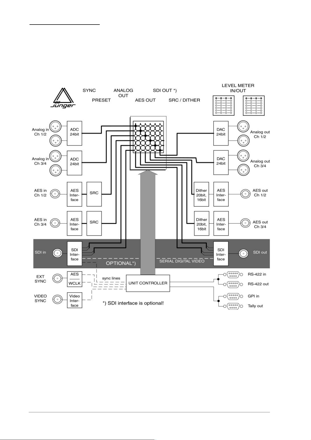
2.3
BLOCK DIAGRAM
page 2-2 operation manual b44, chapter 2 -Function description-
Page 9

3. INSTALLATION
INSTALLATION
The SDI converter/router b44 was carefully packed in the factory and
the packaging was designed to protect the equipment from rough
handling. Please examine carefully the packaging and its contents for
any signs of physical damage, which may have occured in transit.
The SDI converter/router b44 is a device under the safety category
Schutzklasse 1 in keeping with the VDE 0804 standards and may only
used with power supply installations built according to regulations.
Check the voltage details printed at the rear panel are the same as
your local mains electricity supply.
The SDI converter/router b44 is equipped with standard connectors
(see also chapter 3).
Before connecting the SDI converter/router b44 switch the power off at
all connected units
The SDI converter/router b44 is made as standard 19“ unit (EIA
format). It occupies 1 RU (44 mm height) space in a rack.
Please allow at least addititonal 3“ depth for the connectors on the rear
panel.
When installing the unit in a 19“ rack the rear side of the unit needs
some support, especially for mounting in flight cases.
The SDI converter/router b44 should not be installed near units which
produce strong magnetic fields or extreme heat. Do not install the filter
processor directly above or below power amplifiers.
If, during operation, the sound is interrupted or displays no longer
illuminate, or if abnormal odor or smoke is detected immediately
disconnect the power cord plug and contact your dealer or Jünger
Audio.
The SDI converter/router b44 has a digital signal outputs. To the
problem-free combination of following digital devices, the digital signal
processing can be locked to an external clock reference. The selection
of the corresponding input is made with the SYNC switch in the MODE
section. If the chosen sync input is connected with the sync signal, this
signal is used for synchronization automatically. Otherwise the unit is
locking to internal 48 kHz. The digital output signal can be clocked with
the following clock frequencies:
.
3
3.1
UNPACK THE UNIT
3.2
POWER SUPPLY
3.3
CONNECTIONS
3.4
RACK MOUNTING
3.5
OPERATION
SAFETY
3.6
SYNCHRONIZATION
OF
DIGITAL OUTPUT
Operation manual b44, chapter 3 -installation- page 3-1
Page 10

3. INSTALLATION
3.7
AUDIO
CONNECTIONS
SDI VIDEO locks with the clock at the SDI input
(internal 48 kHz)
VIDEO locks with the clock at the Video sync input
(internal 48 kHz)
WCLK locks with the clock frequency at the
external sync input (WCLK, 44.1/48 kHz)
AES locks with the clock frequency at the
external sync input (AES/EBU, 44.1/48 kHz)
Note: SDI sync is available only if SDI input is fitted in the box!
The B44 audio inputs are RFI filtered and with the outputs
electronically balanced and floating. All the audio connectors are via
rear panel mounted connectors. Standard XLR connectors are used.
These are allways wired to the AES standard:
pin 1 X Screen screen
pin 2 L Live audio 0°
pin 3 R Return audio 180°.
Balanced connections are to be preferred whenever the other
equipment provides balanced inputs/outputs. All line level connections
should be wired with twin screened cable for low noise and reliability.
The screens of the cable should be connected at one end only. Input
cable screening therefore needs to be derived from the signal source
end as pin 1 is ground lifted at low frequencies for the inputs.
If the equipment driving the B44 has unbalanced outputs then you will
need to add a wire jumper such that the screen connection of Pin 1 of
the XLR is shorted to Pin 3.
If the equipment being connected to the mpx01 have only unbalanced
inputs, then we recommend still to use a balanced (ie. 2 core shielded
cable) cable where Pin 1 and Pin 3 are connected in the cable ends
away from the B44.
page 3-2 Operation manual b44, chapter 3 -installation-
Page 11

The SDI converter/router b44 can be remote-controlled by means of
parallel GPI contacts. The other way b44 can send signals of specific
device statuses via parallel Tally lines.
use : remote-controlled changeover of presets and more
connector: D-SUB 15pin, female
pinout
GPI in TALLY out
Pin Signal name Logic I/O
1 GPI1+ L/H I
2 GPI2+ L/H I
3 GPI3+ L/H I
4 GPI4+ L/H I
5 GPI5+ L/H I
6 GPI6+ L/H I
7 GPI7+ L/H I
8 test
9 GPI1- L/H I
10 GPI2- L/H I
11 GPI3- L/H I
12 GPI4- L/H I
13 GPI5- L/H I
14 GPI6- L/H I
15 GPI7- L/H I
Pin Signal name alternativ
1 T1, root
2 T2, root
3 T3, root
4 T4, root
5 T5, root
6 T6, root
7 T7/T8, root
8 T1, open contact
9 T2, open contact
10 T3, open contact
11 T4, open contact
12 T5, open contact
13 T6, open contact
14 T7, open contact
15 T8, open contact
Electrical specification:
GPI input On: connection to +3V..+24V
Off: GND
min. 50 ms
Tally output type: normally open relais contacts
Contact rating: 1A 24 VDC, 0,5 A 125 VAC
max. 30 W 62,5 VA
max. 60 VDC, 125 VAC
The SDI converter/router b44 can be remote-controlled by means of
serial remote RS-232/RS-422.
use
: remote-controlled changeover of presets
protocol:
connector:
available on request
D-SUB 9pin, female
3. INSTALLATION
3.8
REMOTE
CONTROL
3.8.1
GPI/TALLY
REMOTE CONTROL
(PARALLEL
REMOTE)
3.8.2
SERIAL REMOTE
CONTROL
(RS-232/RS-422)
Operation manual b44, chapter 3 -installation- page 3-3
Page 12

3. INSTALLATION
3.8.3
CAN BUS
REMOTE
CONTROL
Pin assignments
SERIAL
Pin Signal name Functions
1 RXD + 422 Receive data RS-422
2 TXD-232 Transmit RS-232
3 RXD-232 Receive RS-232
4 Not used
5 GND Ground
6 RXD - 422 Receive data RS-422
7 Not used
8 TXD - 422 Transmit data RS-422
9 TXD + 422 Transmit data RS-422
Electrical specification:
signal in-/outputs RS-232/RS-422
The SDI converter/router b44 can be remote-controlled by means of
serial remote CAN-bus.
use
: remote-controlled changeover of presets
protocol:
available on request
connector:
D-SUB 9pin, male
Pin assignments
CAN
Pin Signal name Functions
1 Not used
2 CAN - CAN low
3 Not used
4 Not used
5 GND GND
6 GND GND
7 CAN + CAN high
8 Not used
9 Not used
CAN-bus termination
CAN-bus (Controller Area Network) has to be terminated at both ends of the
bus chain by 125 Ohms. Therefore termination jumper in the B44 can be used.
#1
125Ohm
CAN+
CAN-
page 3-4 Operation manual b44, chapter 3 -installation-
#2 #3
#4
125Ohm
Page 13

4. LOCATION OF PARTS AND CONTROLS
g
LOCATION OF PARTS AND
CONTROLS
All control elements gives direct access.
Preset buttons
Input level
display
4
4.1.
FRONT PANEL
Output level
display
Sync selection
Input meter selection
Input/Output
router setting
AES output
s
settin
fig. 1: front panel b44
SYNC selection of sync input
PRESET 1...4 storage and recall of presets 1...4
INPUT input meter selection
OUT ANALOG / AES / SDI
output routing related to input
SRC sample rate converter for digital input AES
DITHER dither for digital output AES
SDI IN group selection SDI input
SDI OUT group selection SDI output
OUTPUT output meter selection
Output level
meter selection
SDI
settings
Mains
switch
CONTROL
ELEMENTS
mode
input
router
aes
sdi
output
Operation manual b44, chapter 4 -control elements and displays- page 4-1
Page 14

4. LOCATION OF PARTS AND CONTROLS
A
4.2.
REAR PANEL
SERIAL
REMOTE
SERIAL
CAN
ADDR
SWITCH
SDI
IN/OUT
NALOG IN
ANALOG OUT
GPI
TALLY
SYNC
IN/OUT
DIGITAL
IN/OUT
fig. 2: rear panel b44
POWER INPUT
IEC mains input connector 85-265 V, 50 - 60 Hz with integrated fuse
REMOTE
serial remote interface RS-232
connector: 9pin SUB-D, female
serial remote interface CAN
connector: 9pin SUB-D, male
ADDR - for selection of unit address
GPI
parallel remote interface input, TTL-level
connector: 15pin SUB-D, female
TALLY
parallel remote interface output, TTL-level
connector: 15pin SUB-D, female
SYNC
IN input for ext. sync signal (AES/WCLK/VIDEO, unbal)
connector: BNC socket
WCLK OUT output for WCLK
connector: BNC socket
SDI IN / OUT
Input/output for serial digital video (ITU-R BT.601, SMPTE 272M-A)
Format: Video: 270 Mb/s, 525/625 line rate, 75 Ohm,
BNC socket
AES IN/OUT
input for AES/EBU standard format
connector: BNC socket 75 Ohm, unbalanced
output for AES/EBU standard format
connector: BNC socket 75 Ohm, unbalanced, 0.5V pp
ANALOG IN/OUT
Analog input to 24 bit A/D-converter
Input electronically balanced, XLR connector female
Analog output from 24 bit D/A-converter
Output electronically balanced, XLR connector male
page 4-2 Operation manual b44, chapter 4 -control elements and displays-
Page 15

4. LOCATION OF PARTS AND CONTROLS
Some basic settings are to select by switches on the rear panel or by
switches and jumpers at the internal circuit boards of the unit. These
settings can occur general changes for operation and should made by
qualified engineering staff only.
Rear panel
ADDR Selection of the device address for serial
remote, 16 device addresses selectable
Note: Within a line of remote controlled units every
device needs a different address! The selected
address is valid after next power-on reset of the unit.
Internal
To set any internal jumper or switches it is necessary to open the unit.
PLEASE DO NOT MAKE ANY ALTERATIONS WITH THE MAINS
STILL CONNECTED TO THE UNIT!
Loosen the screws on the top cover and remove. Then you can see
all jumper and switches as shown in the drawing below. After setting
of jumper or switches reassemble the unit in opposite order.
4.3
SWITCHES AND
JUMPERS FOR
CONFIGURATION
SW1&2- SDI group selection and others
ANALOG IN
Level adj.
ANALOG OUT
Level adj.
Main
board
SDI Interface
B44
CAN bus
termination
Baud rate
selection
The 4-channel processors of b40 series fitted with SDI-interface are
compatibel with the standard SMPTE 272M-AB. They support 48 kHz
synchronous audio sampling with 20 bit word length.
The standard allows up to four groups each of four mono audio channels.
(Usually used by most of D-VTR's and other equipment is Group 1 with 48
kHz synchronous sampling.)
Group selection and other settings are made by the front panel
switches. Therefore no switches on the SDI board has to be used.
4.4
CONFIGURATION
OF SDI INTERFACE
Operation manual b44, chapter 4 -control elements and displays- page 4-3
Page 16

Page 17

5. OPERATION
OPERATION
The use of the SDI audio converter/router B44 is very easy.
The setup or the programming of the B44 is made by
adjustment of various settings.
The description is made related to the functions in the sections.
5.1 sync selection
5.2 recall and storage of presets
5.3 input level display
5.4 output routing
5.5 digital input AES with SRC
5.6 digital output AES with dither
5.7 SDI group selection
5.8 Output level display
Pushing the SYNC button is changing the sync selection in the
following loop:
> SDI > VIDEO > WCLK > AES > internal 44.1 > internal 48 >
If the unit is locking to the sync source the LED of the selected sync
input is lighting continously.
If the unit can’t lock to the external sync source the correspondend
LED is flashing. The unit automatically works with internal 48 kHz.
All individual settings for all sections can be stored as presets. 4
presets are storable into the unit.
To recall of presets just push the related preset button. As long
as the settings of the box are the same as with the preset the
related preset LED is lighting.
To store a preset push the related preset button appr. 3 secs
continously. While storing the yellow LED blinks two times.
Note: All former stored preset values are overwritten at the
moment of new storage into this preset! Just as after
initialization of the unit all presets are overwritten with factory
setups.
5
5.0
DESCRIPTION OF
OPERATIONS
5.1
SYNC SELECTION
5.2
RECALL AND
STORAGE OF
PRESETS
operation manual b44, chapter 5 -Operation- page 5-1
Page 18

5. OPERATION
5.3
INPUT LEVEL
DISPLAY
5.4
OUTPUT ROUTING
5.5
INPUT AES WITH
SRC
5.6
OUTPUT AES WITH
DITHER
5.7
SDI GROUP
SELECTION
5.8
OUTPUT LEVEL
DISPLAY
Pushing the INPUT button changes the input of the input level
meter display.
Pushing the button for one of the six output pairs is changing the
connected input pair (selection pairwise). This is shown by the
related LED.
One and the same input can be connected to all available
outputs at the same time. One output pair can be connected to
just one input pair only.
Pushing the SRC button is switching the sample rate conversion
for the AES inputs ON pairwise:
> OFF > IN ½ > IN ¾ > IN ½ and IN ¾ > OFF
If the SRC is switched ON the related input is free running. That
means any incoming sample rate from 32…52kHz is converted
to the sync clock of the box.
The digital input signal can have a word length of 24 bit. The
information of a 24 bits signal is not more storable linear in most
cases. One must shorten 24 bits data word to 20 or 16 bit word length
(SDI is capable for 20 bit only!).
Pushing the DITHER button is switching the dither algorithm for the
AES outputs:
> OFF > 20bit > 16 bit > OFF >
In order to receive a better sound quality during cut down the data to 20 or 16
bit, one must redither the material. This is done by calculating random
numbers (dither signal) and add a random number to every sample. Then it
will be cut off to 16 bit. As a result, the bit with least weight (LSB) is put in
such a way that it corresponds best to the information of the last bits
following available ones no more and makes less distortions as hissing in the
signal. Dither is switched off for digital zero signals (auto-blacking).
With the SDI IN and the SDI OUT buttons the group selection
for the SDI interface can be made. SDI input and output can
deembed and embed with two different groups!
Pushing the OUTPUT button changes the input of the output
level meter display.
page 5-2 operation manual b44, chapter 5 -Operation-
Page 19

6. TECHNICAL SPECIFICATIONS
TECHNICAL
SPECIFICATIONS
sample rate : 44.1/48 kHz
audio data format : 24 bit (AES/EBU), 20 bit (SDI)
DIGITAL IN/OUT
AES/EBU
connector : BNC, 75 Ohm, coaxial
input format : AES professional, AES consumer
output format : same as input format
SDI IN/OUT (only for SDI version)
connector : BNC, 75 Ohm, coaxial
data rate : 270 Mb/s, 525/625 Line rate
format : serial digital component video 4:2:2
with embedded audio
(ITU-R BT.601, SMPTE 272M-A)
ANALOG IN/OUT
ANALOG IN
Resolution 24bit
sample rate 44.1/48kHz
dynamic range 103dB (RMS)
THD+N <0.002% @ max. input level
frequency response 20Hz...20kHz (FS=48kHz) (+/-0.5dB)
CMRR –80dB @ 50Hz
max. input level +22dBu @ 0dBFS
input impedance 10 kOhm, floating balanced
connector XLR, 1-screen, 2-live, 3-return
ANALOG OUT
Resolution 24bit
sample rate 44.1/48kHz
dynamic range 103dB (RMS)
THD+N <0.002% @ max. input level
frequency response 20Hz...20kHz (FS=48kHz) (+/-0.5dB)
max. output level +22dBu @ 0dBFS
input impedance 30 Ohm, floating balanced
connector XLR, 1-screen, 2-live, 3-return
digital signal
processing
digital
in- / outputs
analog
in- / outputs
6
operation manual b44, chapter 6-Technical specifications- page 6-1
Page 20

6. TECHNICAL SPECIFICATIONS
sync
in- / outputs
SYNC IN
WCLK connector : BNC, 1kOhm, coaxial
level : TTL-level
input format : Wordclock
AES/EBU connector : BNC, 75 Ohm, coaxial
level : 0,5 ... 5 Vpp
input format : AES professional, AES consumer
VIDEO connector : BNC, 75 Ohm, coaxial
level : 0...1 Vpp
input format : Blackburst or PAL/NTSC composite video
remote control
REMOTE
serial remote interface RS-232 in/out
level : TTL
connector : 9 pin SUB-D female
serial remote interface CAN
level : 5V CAN
connector : 9 pin SUB-D male
GPI parallel remote
level : opto coupler, 3..24V control voltage
connector : 15 pin SUB-D female
Tally Out
level : relais contact
connector : 15 pin SUB-D female
general
power consumption : appr. 15 VA
dimensions : 19“, 1 RU, 250 mm depth
weight : appr. 5 kg
optional : programmable remote control brc4x
page 6-2 operation manual b44, chapter 6-Technical specifications-
Page 21

7. WARRANTY AND SERVICE INFORMATION
WARRANTY AND SERVICE
INFORMATION
JÜNGER AUDIO grants a two-year warranty on the
SDI converter router b44
If the unit has to be serviced, please send it, ideally in the
original box, to:
JÜNGER AUDIO - Studiotechnik GmbH
Justus-von-Liebig-Str. 7
D - 12489 Berlin
GERMANY
Tel.: (*49) -30-677721-0
Fax.: (*49) -30-677721-46
7
operation manual b44, chapter 7 -Warranty and service information- page 7-1
Page 22

Page 23

KONFORMITÄTSERKLÄRUNG
DECLARATION OF CONFORMITY
Geräteart : 4ch SDI audio converter/router
Type of equipment : 4ch SDI audio converter/router
Produkt / Product : b44
Das bezeichnete Produkt stimmt mit den Vorschriften folgender EU-Richtlinie(n) überein:
The aforementioned product complies with the following Europaen Council Directive(s):
89/336/EWG (geändert durch 91/263/EWG und 92/31/EWG)
(changed by 91/263/EEC and 92/31/EEC)
Richtlinie der Rates zur Angleichung der Rechtsvorschriften der
Mitgliedsstaaten über die elektromagnetische Verträglichkeit
Council Directive on the approximation of the laws of the
Member States relating to electromagnetic compatibility
73/23/EWG (geändert durch 93/68/EWG)
(changed by 93/68/EEC)
Richtlinie des Rates vom 19. Februar 1973 betreffend elektrische
Betriebsmittel zur Verwendung innerhalb bestimmter
Spannungsgrenzen
Council Directive of February 19th 1973 concerning electircal
equipment for operation within certain voltage limits
Zur vollständigen Einhaltung dieser Richtlinie(n) wurden folgende Normen herangezogen:
To fully comply with this(these) Directive(s), the following standards have been used:
EN 55022 : 1987
EN 50082-1 : 1993
EN 60065 : 2002
Dieser Erklärung liegen zugrunde : Prüfbericht(e) des EMV-Prüflabors
Interne Vorschriften zur Sicherheits-Prüfung
This certification is based on : Test report(s) generated by EMC-test laboratory
Internal regulations for safety check
MEB Messelektronik Berlin : Kalibrier- und Prüflabor
accredited EMC laboratory
Aussteller / Holder of certificate : Jünger Audio Studiotechnik GmbH
Justus-von-Liebig-Strasse 7
D - 12489 Berlin
Berlin, 18.03.2003 .....................................................................................
(Ort/Place) (Datum/Date) (Herbert Jünger, Geschäftsführer/Managing Director)
Page 24

 Loading...