

Page 1
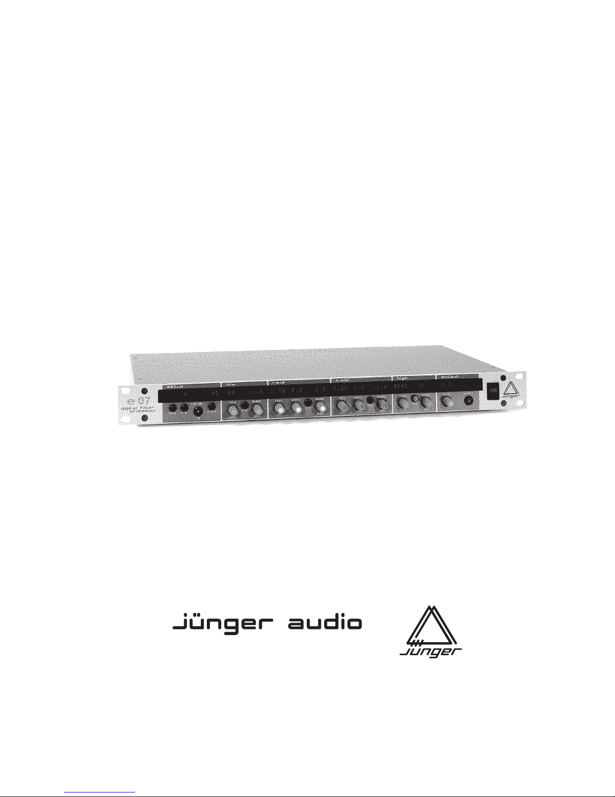
DIGITAL
FILTER
PROCESSOR
model e07
operation manual
rev. 0.41
Rudower Chaussee 5 (Geb. 9.51), D -12489 Berlin, Germany
Telefon +49 (030) 677721- 0 · Fax +49 (030) 677721- 46
Studiotechnik GmbH
Page 2
INTRODUCTION
The digital filter processor e07 is a high quality studio device for
audio production and mastering. It brings the sound of the best
analogue filters into the digital world.
The primary feature of this new unit lies in it's ability to process
audio in the digital domain using digital filters operating at
higher sample rates. Increasing the sample rate to 88.2 or 96
kHz, the "High Sampling Mode" does not limit the magnitude and
phase response of the filtering process to 22 or 24 kHz as most
digital filters do. Doubling the sample rate increases the audio
range that can be processed. High frequencies are faithfully
reproduced in the same vibrant and natural manner as the finest
analogue filters.
The digital filter processor Model e07 is a 4-band parametric
equaliser. It is possible to use each filter band as a normal
parametric or as a dynamic equaliser, ie. a digital de-esser.
An integral digital limiter prevents clipping of boosted signals.
The Model e07 is a 24 bit device sampling at 96kHz and is
designed specifically for the highest quality, high resolution
recording and reproduction.
* Outstanding signal quality achieved by high sampling
processing
* Conventional operation from the front panel with rotary
knobs for direct control of all parameters
* Each filter band can be used as a dynamic filter,
ie. de-esser
* Integral digital limiter prevents clipping
* Stereo or dual channel mode
* Timecode snapshot automation
* User-friendly preset and recall functions
* Ready for integration into 96 kHz systems
0
Page 3
CONTENTS
2. Installation .............................................................................
2.1 Unpack the unit ...............................................................
2.2 Power supply ...................................................................
2.3 Connections ....................................................................
2.4 Rack mounting ................................................................
2.5 Operation safety ..............................................................
3. Location of parts and controls ...............................................
3.1 Front panel ......................................................................
3.2 Rear panel .......................................................................
4. Operation ..............................................................................
4.0 Description of operations related to functions .................
4.1 Equaliser .........................................................................
Filter bands ......................................................................
Output ..............................................................................
4.2 Dynamic equaliser ...........................................................
Filter bands .......................................................................
Output ..............................................................................
Dynamic mode .................................................................
4.3 Equaliser (2-channel mode) .............................................
Status display ..................................................................
Mode setting ...................................................................
Filter bands .......................................................................
Output ..............................................................................
Selection left channel / right channel ...............................
4.4 Low cut / high cut filters ...................................................
Status display ..................................................................
Setting for adjustment .....................................................
Low cut .............................................................................
High cut ...........................................................................
5
5
5
5
5
5
6
6
6
8
8
9
9
9
10
10
10
10
11
11
11
11
11
11
12
12
12
12
12
1
Page 4

4.5 A/B comparison ...............................................................
Status display .................................................................
Memory selection ............................................................
Loading of adjustments into A or B memory ...................
4.6 Presets ............................................................................
Status display ..................................................................
Saving presets ................................................................
Loading presets into A or B .............................................
Loading factory preset into B ..........................................
Copy presets ...................................................................
Rename presets ..............................................................
4.7 Snapshot automation .......................................................
Generating snapshots by capture mode .........................
Disactivating capture mode .............................................
Creating snapshots by edit mode ....................................
Editing snapshots by edit mode .......................................
Deleting of snapshots ......................................................
Copying snapshots by edit mode ....................................
Playback an EDL by play mode (autoplay) ......................
Playback an EDL stepwise (without timecode) ................
Clearing an EDL ..............................................................
4.8 Utilities ..............................................................................
Selection of 2-channel mode ...........................................
Selection of timecode ......................................................
Selection of channel status ..............................................
Data saving .....................................................................
Saving preset and EDL data ...........................................
Loading preset and EDL data .........................................
Showing number and name of stored data block ............
4.9 Remote control .................................................................
GPI Remote control .........................................................
Serial remote control .......................................................
5. Boot display and trouble shooting .........................................
5.1 Boot display .....................................................................
5.2 Error display and trouble shooting ...................................
13
13
13
13
14
14
14
15
15
16
17
18
18
18
19
19
20
21
22
22
23
24
24
25
26
27
27
28
29
30
30
31
32
32
32
Page 5

6. Application notes ...................................................................
6.1 Digital filter at 96 kHz .......................................................
6.2 Dynamic equaliser ...........................................................
6.3 Working in high sampling mode (96 kHz) ........................
6.4 Influence of signal delay time ..........................................
7. Technical specifications ........................................................
8. Warranty and service information .........................................
33
33
34
35
36
37
39
Page 6

5
INSTALLATION
The digital filter processor e07 was carefully packed in the
factory and the packaging was designed to protect the
equipment from rough handling. Please examine carefully the
packaging and its contents for any signs of physical damage,
which may have occured in transit.
The digital filter processor e07 is manufactured under the safety
category Schutzklasse 1 in keeping with the VDE 0804
standards.
Check the voltage details printed at the rear panel are the same
as your local mains electricity supply.
The digital filter processor e07 is equipped with standard
connectors (see chapter 3).
Before connecting the digital filter processor e07 switch the
power off at all connected units.
The digital filter processor e07 is made as standard 19“ unit (EIA
format). It occupies 1 RU (44 mm height) space in a rack.
Please allow at least addititonal 3“ depth for the connectors on
the rear panel.
When installing the unit in a 19“ rack the rear side of the unit
needs some support, especially for mounting in flight cases.
The filter processor should not be installed near units which
produce strong magnetic fields or extreme heat. Do not install
the filter processor directly above or below power amplifiers.
If, during operation, the sound is interrupted or displays no
longer illuminate, or if abnormal odor or smoke is detected
immediately disconnect the power cord plug and contact your
dealer or Jünger Audio.
2.1
UNPACK THE UNIT
2.2
POWER SUPPLY
2.3
CONNECTIONS
2.4
RACK MOUNTING
2.5
OPERATION
SAFETY
2
Page 7
6
LOCATION OF PARTS AND
CONTROLS
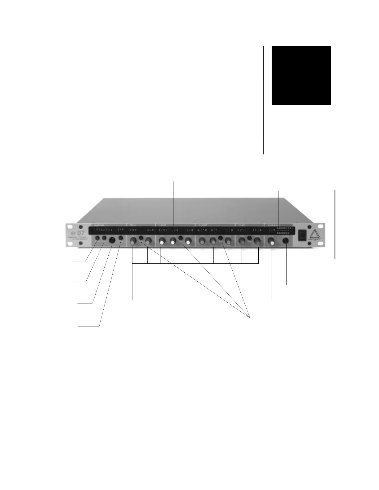
All control elements give direct access.
In menu modes the alphanumeric display above the related
button or rotary knob shows the specific function.
MODE switches between normal user mode (4 band EQ)
and MENU mode
A/B switches between A and B memory (see 4.5)
CAPTURE activates capturing of snapshots (see 4.7)
L/R switches between left/right channel in
2-channel mode (see 4.3)
FILTER switches between normal user mode (4 band EQ)
and low and high cut filter adjustment (see 4.4)
3.1.
FRONT PANEL
SETUP SECTION
3
setup
section
low section
l-mid section
h-mid section
high section
output section
mode
button
A/B
button
Capture
& L/R
button
filter
button
mains
switch
bypass
button
output gain
control
dynamic
button
rotary controls
for
frequency,
width, range
Page 8
3. LOCATION OF PARTS AND CONTROLS
7
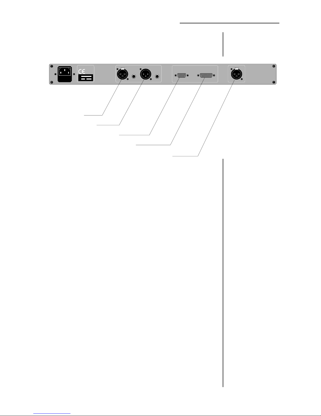
digitalf ilter e07
230 V
50Hz
200 mA
Nr
DIGITAL AUDIO
OUT
IN
S/PDIF S/PDIFAES/EBU AES/EBU
TIMECODE
LTC-IN
REMOTE
RS-232
GPI
POWER INPUT
IEC mains input connector 230 V, 50 Hz (UK: 240 V, 50 Hz; JAPAN: 100 V,
60 Hz; USA: 127 V, 60 Hz) with integrated fuse
DIGITAL IN
input for AES/EBU standard format
input: XLR female panel jack
1- open, 2-3 signal, balanced, max. 5 Vpp
input for S/PDIF standard format
RCA socket
DIGITAL OUT
output for AES/EBU standard format
output: XLR male panel jack
1- open, 2-3 signal, balanced, max. 5 Vpp
output for S/PDIF standard format
RCA socket
TIMECODE IN
input for LTC timecode format
input: XLR female panel jack
1- open, 2-3 signal, balanced, more than -10 dBu
REMOTE
serial remote interface RS-232
connector: 9pin SUB-D, male
GPI remote interface
connector: 15pin SUB-D, female
3.2.
REAR PANEL
DIGITAL
DIGITAL OUT
SERIAL REMOTE
GPI REMOTE
TIMECODE IN
Page 9
8
OPERATION
The operation of the digital filter processor e07 is described in
the following chapters.
The description is made related to the main functions of the
unit.
4.1 equaliser
4.2 dynamic equaliser
4.3 equaliser (2-channel mode)
4.4 low cut / high cut filters
4.5 A / B comparison
4.6 presets
4.7 snapshot automation
4.8 utilities
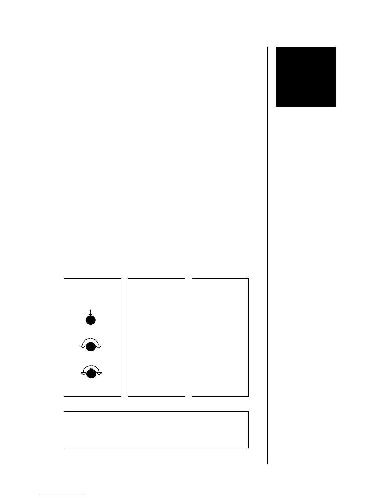
Following syntax is used:
SYMBOL NAME ACTIVITY
DISPLAY:
4.0
DESCRIPTION OF
OPERATIONS
RELATED TO
FUNCTIONS
describes
action or function
by use of button or
rotary knob
describes
the name of
button or
rotary knob
NAME
name, as printed on
front panel
NAME
name, as displayed
on alphanumeric
display above
button or knob
describes
how to use
button or
rotary knob
describes the status or information shown on the display
name status/name as displayed
<NAME> sort of status/name on display
4
push
push + turn
turn
Page 10
4. OPERATION
9
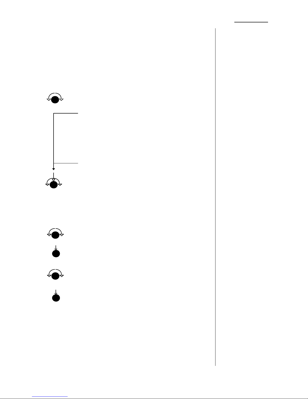
For use as 4-band parametric equaliser in stereo mode.
All settings are identical for each of the two channels.
Each section can be switched off individual.
A/B comparison is available for two stereo parameter sets.
Limiter is working in stereo mode.
All adjustments are storable in presets.
FREQ fine resolution frequency adjustment,
related to max. boost/cut
low (20 ...500 Hz),
display:20 ... 500
l-mid (50 ... 20.000 Hz)
(mid1) display: 50 ... 20.00
h-mid (50 ... 20.000 Hz)
(mid2) display: 50 ... 20.00
high (2.000 ... 20.000 Hz)
display: 2.00 ... 20.00
FREQ selection of filter type for low and high filter
and adjustment of Q-factor
shelving filter or
peak filter Q = 0.4 ...8
(minimum center frequency for
low peak filter is 50 Hz.)
RANGE boost/cut control (-15 ...+15 dB),
display: -15.0 ...15.0
RANGE bypass for the filter band,
display: OFF
GAIN output level control (-15 ...+15 dB),
display: -15.0 ...15.0
GAIN bypass for gain control (gain = 0dB)
display: OFF
FILTER BANDS
4.1
EQUALISER
OUTPUT
turn
push
turn
push
turn
push+turn
Page 11
4. OPERATION
10
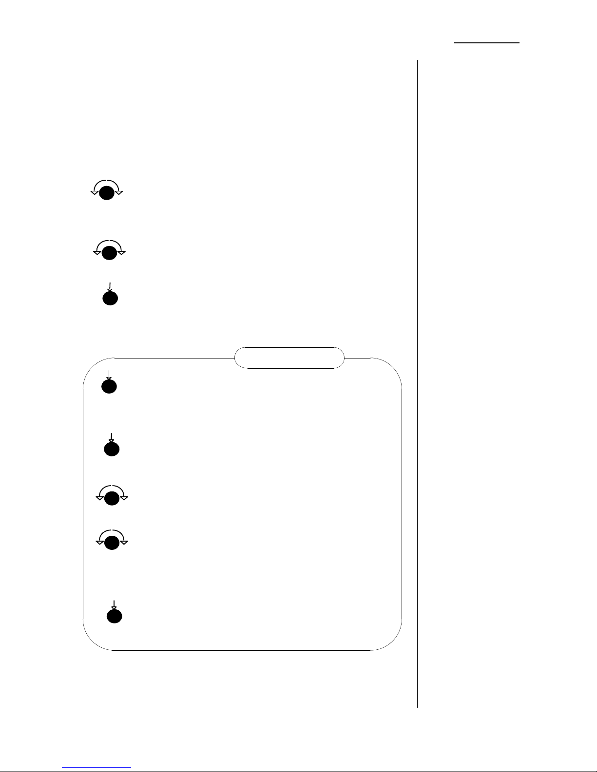
For use as dynamic equaliser in stereo mode. A maximum of
two sections can be used in dynamic mode at the same time.
All settings are identical for each of the two channels.
Each section can be switched off individual.
A/B comparison is available for two stereo parameter sets.
Limiter is working in stereo mode.
Dynamic equaliser adjustments are storable in presets.
FREQ fine resolution frequency adjustment,
related to max. boost/cut
GAIN output level control (-15 ...+15 dB),
display: -15.0 ...15.0
GAIN bypass for gain control (gain = 0dB)
display: OFF
DYN set the dynamic function for filter band
display:RDUC
if cut is adjusted (-15 ... 0 dB)
ENHC
if boost is adjusted (0.1 ... +15 dB)
FREQ threshold level and range display
display: -50 ... -00 and -15.0 ...15.0
FREQ threshold level adjustment (-50 ... 0 dBFS)
display: -50 ... -00
RANGE boost/cut control (-15 ...+15 dB),
display: RDUC and bargraph
if cut is adjusted (-15 ... 0 dB)
ENHC and bargraph
if boost is adjusted (0.1 ... +15 dB)
RANGE bypass for the filter band,
display: OFF (if filter band is bypassed)
4.2
DYNAMIC
EQUALISER
see also
chapter 6
APPLICATION
NOTES
FILTER BANDS
OUTPUT
DYNAMIC MODE
turn
push
push
turn
turn
pushpush
dynamic mode
push
turn
Page 12
4. OPERATION
11
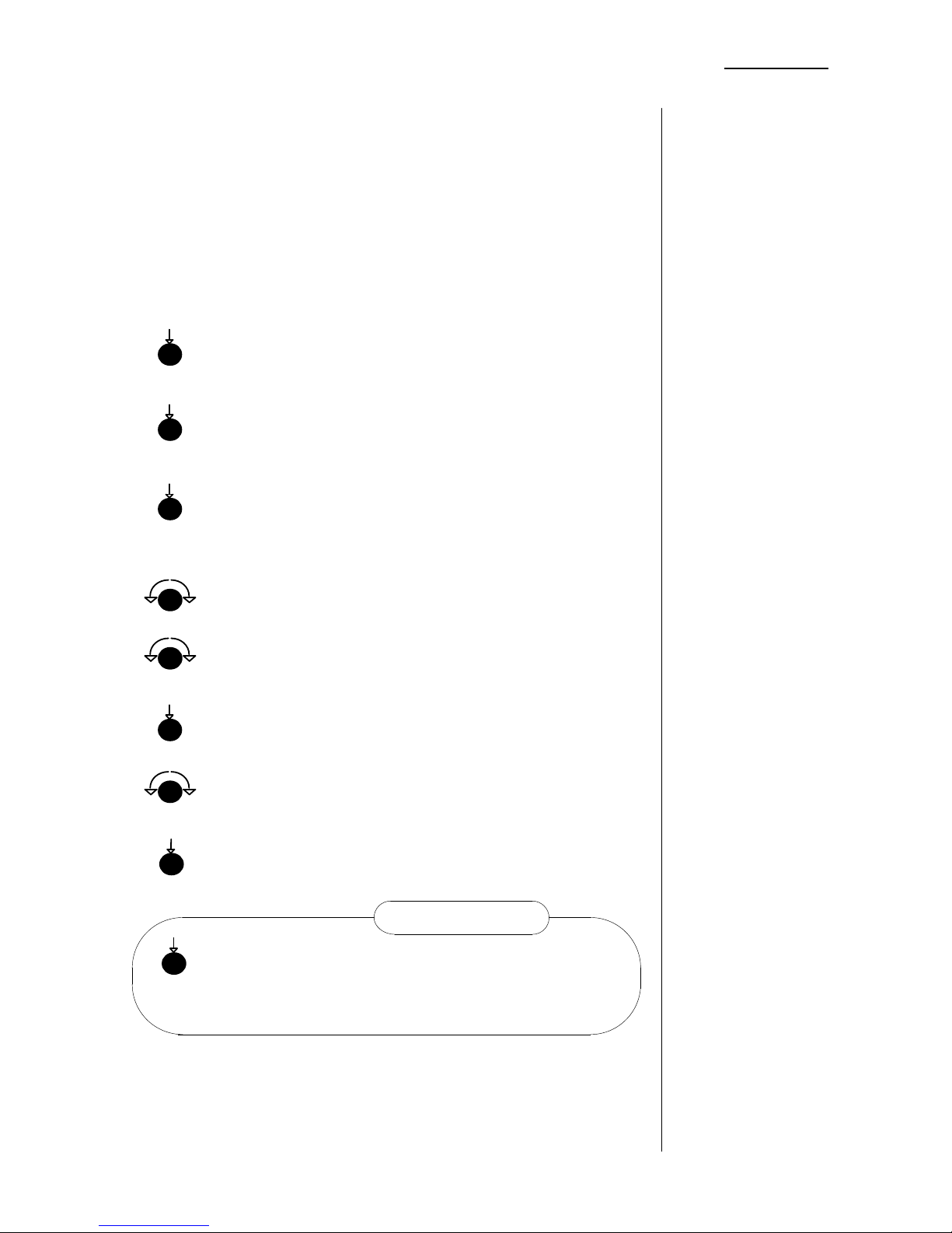
For use as 4-band parametric equaliser in 2-channel mode.
All settings can be different for each of the two channels.
Each section can be switched off individually.
A/B comparison is available for two pairs of L/R parameter sets.
Limiter is working unlinked in 2-channel mode.
All adjustments are storable in presets.
Dynamic equaliser is not working in 2-channel mode.
display above L/R button L 2-ch mode, left channel selected
R 2-ch mode, right channel selected
blank stereo mode
MODE Selection of MAINMENU
UTIL Selection of UTILITY menu
2-CH Selection of 2-channel mode
FREQ fine resolution frequency adjustment,
related to max. boost/cut
RANGE boost/cut control (-15 ...+15 dB),
display: -15.0 ...15.0
RANGE bypass for the filter band,
display: OFF
GAIN output level control (-15 ...+15 dB),
display: -15.0 ...15.0
GAIN bypass for gain control (gain = 0dB)
display: OFF
L/R switching between left and right channel
display: L (if left channel is selected)
R (if right channel is selected)
4.3
2-CHANNEL
MODE
STATUS DISPLAY
MODE SETTING
FILTER BANDS
OUTPUT
SELECTION
LEFT CHANNEL /
RIGHT CHANNEL
push
push
push
turn
push
2-channel mode
push
turn
push
turn
Page 13
4. OPERATION
12
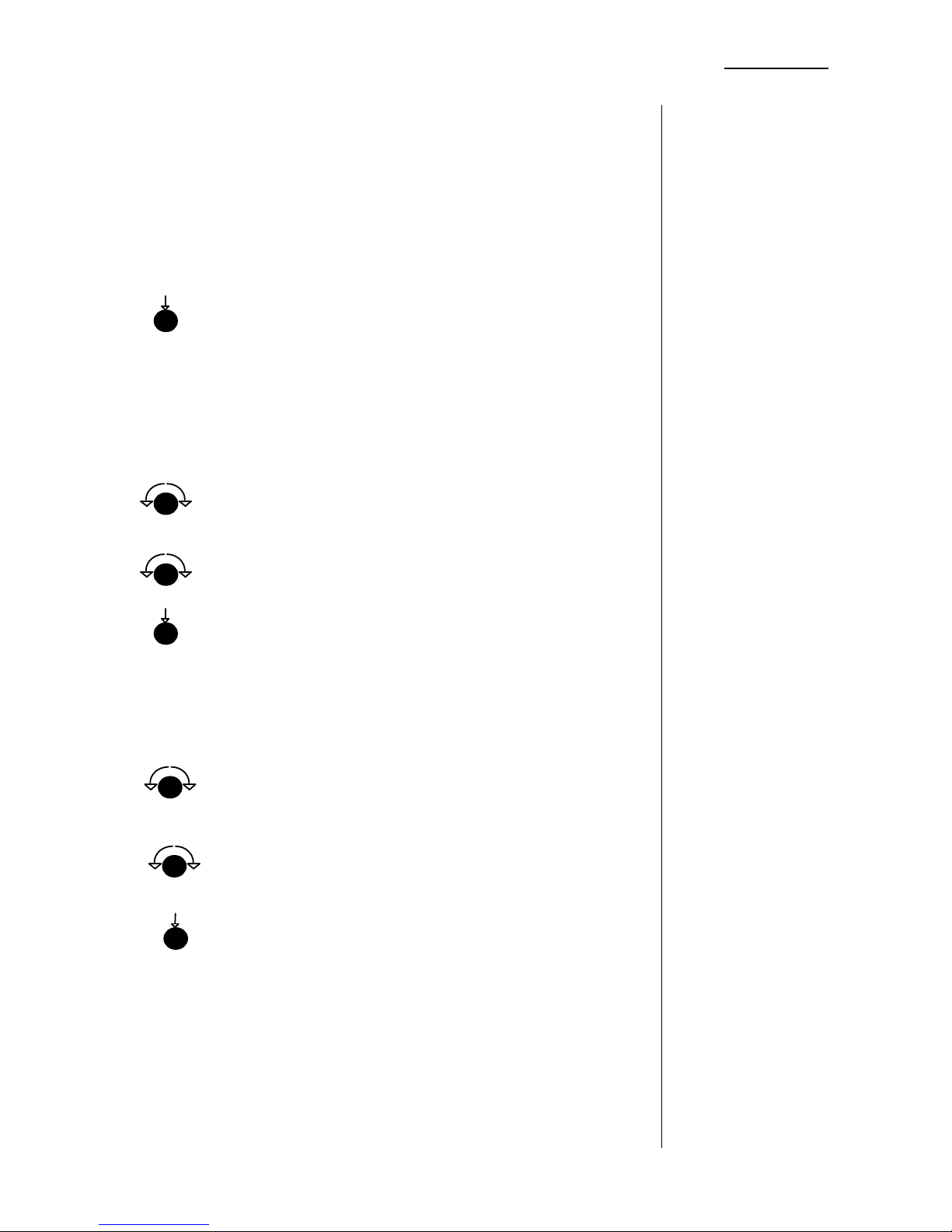
Filters for removal of disturbances and for bandwidth limiting.
All settings are identical for each of the two channels.
Each filter can be switched off individually.
All adjustments are storable in presets.
Display above FILTER button LCHC low cut and high cut active
LC only low cut active
HC only high cut active
OFF low cut and high cut bypassed
FILTER Selection of LOW CUT / HIGH CUT
filter adjustments
display: LCUT and parameters
HCUT and parameters
frequency range 2 ... 120 Hz
-6, -12 or -18 dB per octave
FREQ frequency adjustment (2 ...120 Hz),
fine resolution,
display: 2 ... 120
RANGE slope control (-6, -12 or -18 dB per octave)
display: 6dB ...18dB
RANGE bypass for the low cut filter,
display: OFF (if low cut is bypassed)
frequency range 2.000 ... 20.000 Hz
-6, -12 or -18 dB per octave
FREQ frequency adjustment (2.000 ...20.000 Hz),
fine resolution,
display: 2.00 ... 20.0
RANGE slope control (-6, -12 or -18 dB per octave)
display: 6dB ...18dB
RANGE bypass for the high cut filter,
display: OFF (if high cut is bypassed)
STATUS DISPLAY
SETTING FOR
ADJUSTMENT
4.4
LOW CUT /
HIGH CUT FILTER
LOW CUT
LOW SECTION
HIGH CUT
HIGH SECTION
push
turn
turn
push
push
turn
turn
Page 14
4. OPERATION
13
There are existing two memorys for fast and convenient
comparison of adjustments.
A - memory, parameter are adjustable
B - memory, parameter are adjustable
Note! If the filter is working in 2-channel mode both memories A and B
contains left channel and right channel parameters. The selected channel is
displayed in the status display above L/R button (see 4.3), the selection can
be changed by L/R button.
Display above A/B button A memory A selected
all adjustments possible,
standard working mode
B memory B selected
all adjustments possible,
A/B Selection of A or B memory
display: A or B
See following chapter: 4.6 OPERATION - PRESETS
- LOADING PRESETS -
4.5
A/B
COMPARISON
STATUS DISPLAY
MEMORY
SELECTION
LOADING OF
ADJUSTMENTS
INTO A OR B
MEMORY
push
Page 15
4. OPERATION
14
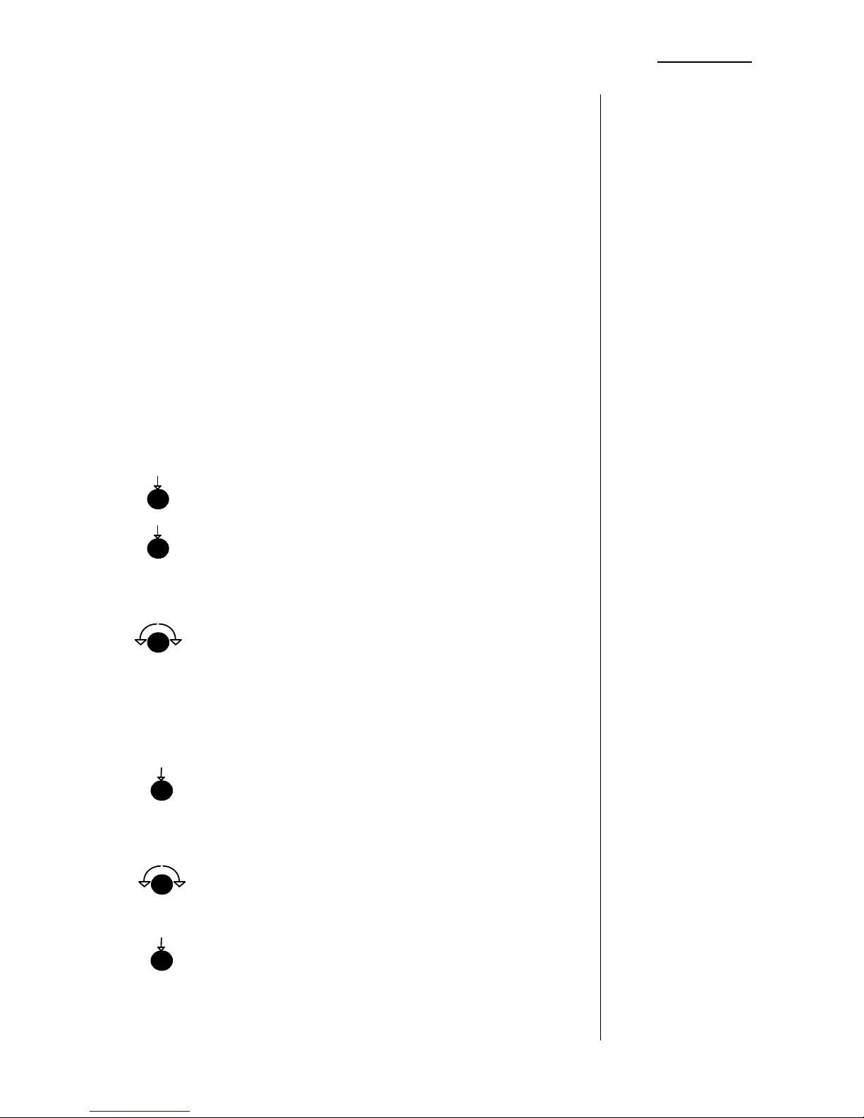
The filter processor e07 offers a convenient preset storage
system for saving and loading of parameters. Following
parameters are stored in presets:
equaliser bands (also dynamic equaliser)
2-channel mode equaliser bands
low cut / high cut filter
output gain (also for 2-channel mode)
bypass functions (also for 2-channel mode).
Until 50 presets can be stored into the unit. In 2-channel mode
both parameter sets for left and for right channel are stored in
one preset.
Presets can be named by the user.
Presets can be used for A/B comparison and for snapshot
automation.
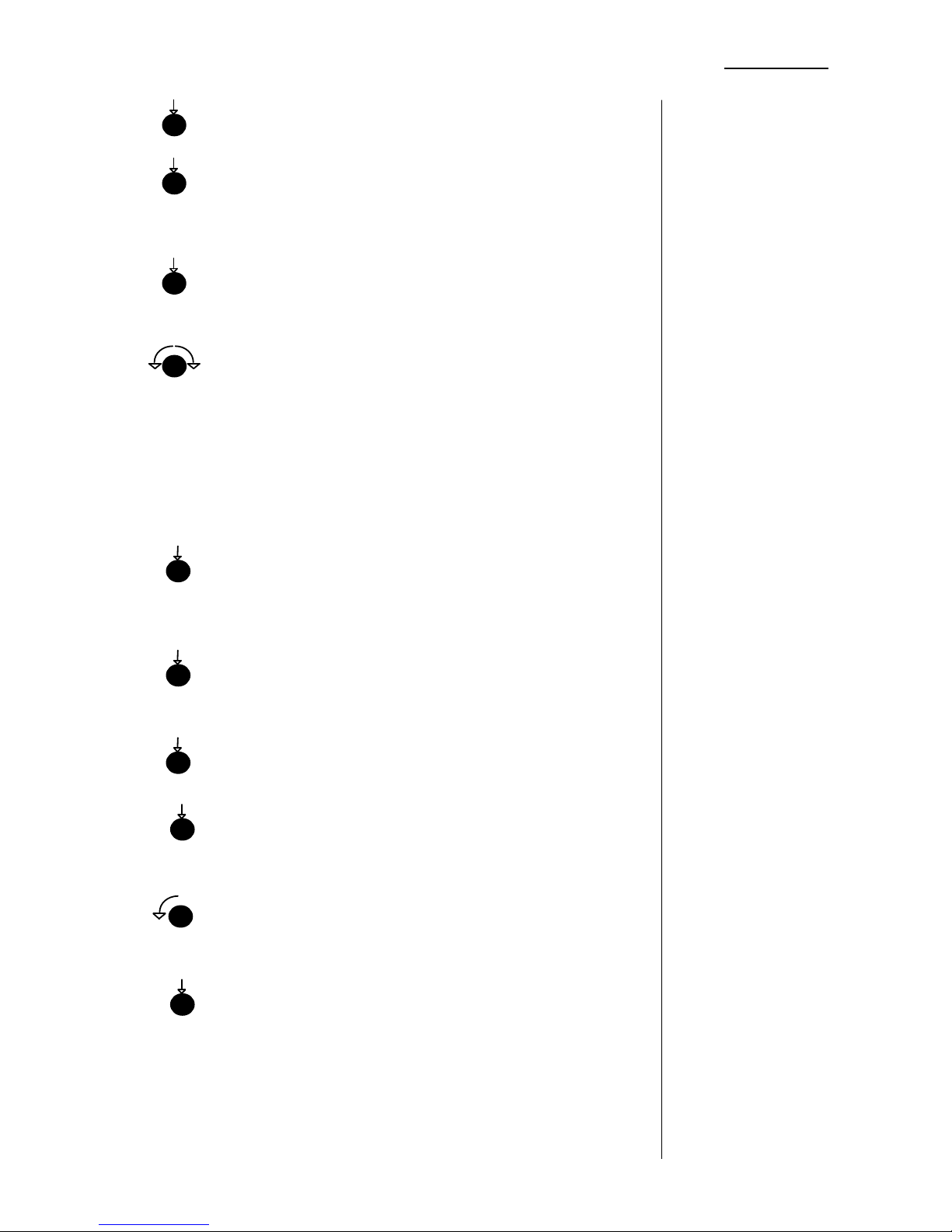
Display above MODE button P** preset no.** loaded (into A or B)
MODE Selection of MAINMENU
SAVE PRST Selection of PRESET - SAVE MODE
display: SAVE ð PRST ** <name P**>
[** = number of last loaded preset (or 01, if
no preset was loaded before)]
FREQ/ENTER Selection of preset number xx for parameter
(low section) saving.
display: SAVE ð PRST xx <name Pxx> or st data or 2-ch data
Attention! Preset was used before and will
be overwritten after saving.
or
SAVE ð PRST xx NO DATA
Free preset for data saving (unused before).
FREQ/ENTER Saving of actual parameter set into preset
xx
(low section) Push two times to save with default name.
display: NAME PRST xx P R E S E T X X
or
ALL KNOBS Changing of the default name (PRESETxx)
(low RANGE into an individual name (10 digits), push the
... output GAIN) knobs to generate space
FREQ/ENTER Saving preset xx with individual name
(low section)
4.6
PRESETS
STATUS DISPLAY
SAVING PRESETS
(saving of actual
work parameter
[memory A or B]
into preset xx)
push
push
turn
push
turn
push
Page 16
4. OPERATION
15
MODE Selection of MAINMENU
LOAD PRST Selection of PRESET - LOAD MODE
display: LOAD A ï PRST ** <name P**>
[** = number of last loaded preset (or 01, if
no preset was loaded before)]
A/B Selection of A or B memory
display: as before or LOAD B ï PRST ** <name P**>
FREQ/ENTER Selection of preset number xx
(low section)
display: LOAD A ï PRST xx <name Pxx>
or
LOAD A ï PRST xx NO DATA
no parameter saved in preset, not
loadable!
LOAD A ï PRST xx 2-ch data
2-ch preset in stereo mode, not loadable
LOAD A ï PRST xx st data
2-ch preset in stereo mode, not loadable
FREQ/ENTER Loading of preset xx into memory A or B
(low section)
MODE Selection of MAINMENU
LOAD PRST Selection of PRESET - LOAD MODE
display: LOAD A ï PRST ** <name P**>
[** = number of last loaded preset (or 01, if
no preset was loaded before)]
A/B Selection of A or B memory
display: as before or LOAD B ï PRST ** <name P**>
FREQ/ENTER Selection of preset PRE0 (DEFAULT)
(low section)
display: LOAD A or B ï Pre0
FREQ/ENTER Loading of default parameter values into
(low section) memory A or B
LOADING
PRESETS
into A or B
LOADING
FACTORY
PRESET
into A or B
push
push
turn
push
push
push
push
push
turn
push
Page 17
4. OPERATION
16
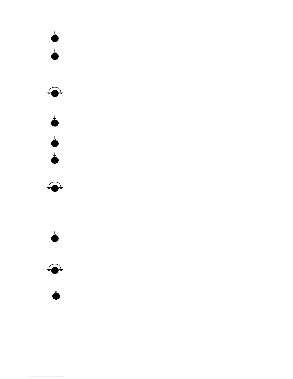
MODE Selection of MAINMENU
LOAD PRST Selection of PRESET - LOAD MODE
display: LOAD A ï PRST 01 ** <name P**>
[** = number of last loaded preset (or 01, if
no preset was loaded before)]
FREQ/ENTER Selection of preset number xx
(low section)
display: LOAD A ï PRST xx <name Pxx>
FREQ/ENTER Loading of preset xx into memory A
(low section)
MODE Selection of MAINMENU
SAVE PRST Selection of PRESET - SAVE MODE
display: SAVE ð PRST xx <name Pxx>
FREQ/ENTER Selection of preset number yy for preset
(low section) copy.
display: SAVE ð PRST yy <name Pyy>
Attention! Preset was used before and will
be overwritten after saving.
or
SAVE ð PRST yy NO DATA
Free preset for copy (unused before).
FREQ/ENTER Copy of preset xx into preset yy.
(low section) Push two times to save with default name.
display: NAME PRST yy <name Pxx>
or
ALL KNOBS Changing of the source name (PRESETxx)
(low RANGE into an individual name (10 digits), push
... output GAIN) knob to generate space
FREQ/ENTER Saving of copied preset xx with individual
(low section) name into preset yy.
COPY PRESETS
push
push
push
push
push
turn
push
turn
push
turn
Page 18
4. OPERATION
17
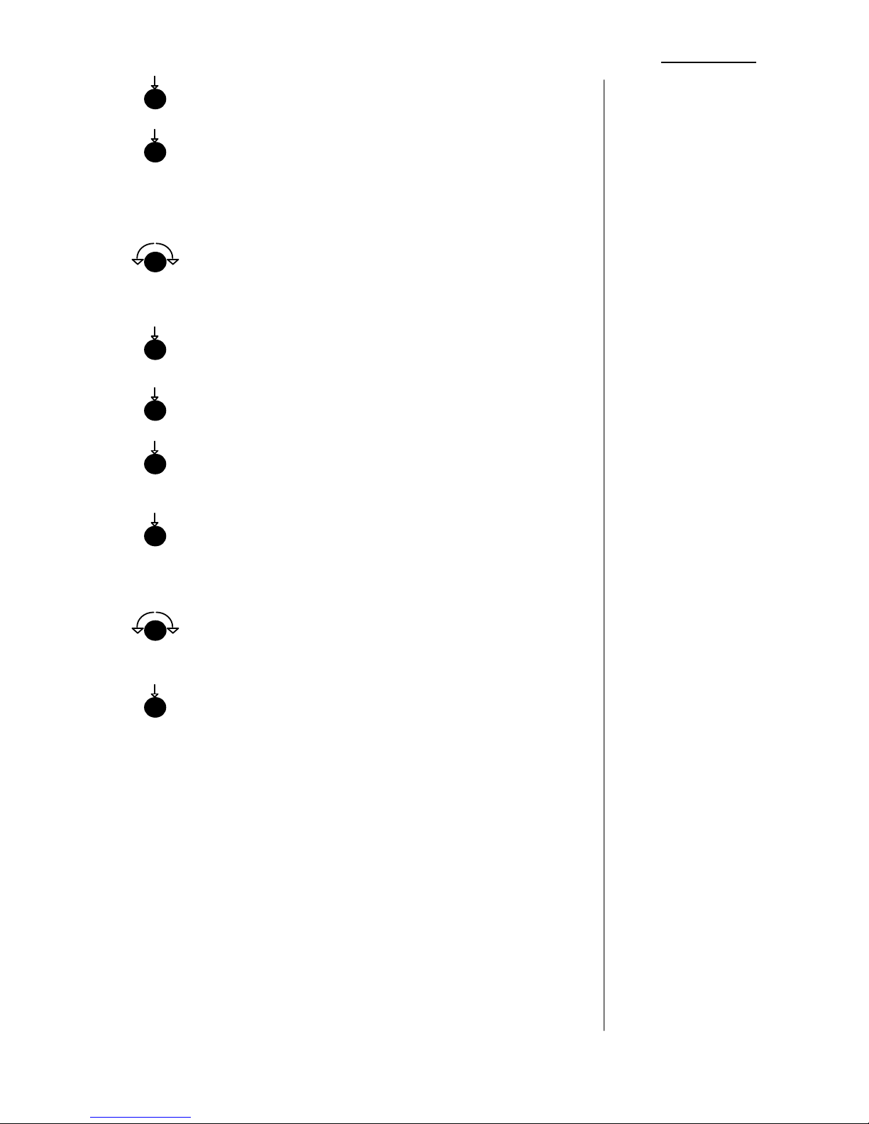
MODE Selection of MAINMENU
LOAD PRST Selection of PRESET - LOAD MODE
display: LOAD A ï PRST 01 ** <name P**>
[** = number of last loaded preset (or 01, if
no preset was loaded before)]
FREQ/ENTER Selection of preset number xx
(low section)
display: LOAD A ï PRST xx <name Pxx>
FREQ/ENTER Loading of preset xx into memory A
(low section)
MODE Selection of MAINMENU
SAVE PRST Selection of PRESET - SAVE MODE
display: SAVE ð PRST xx <name Pxx>
FREQ/ENTER Copy (save back) of preset xx into preset
xx.
(low section)
display: NAME PRST xx <name Pxx>
ALL KNOBS Changing of the source name <name Pxx>
(low RANGE for a new individual name (10 digits)
... output GAIN)
FREQ/ENTER Saving of new name for preset xx.
(low section)
RENAME
PRESETS
(COPY PRESETS
AT SAME PLACE
WITH NAME
CHANGE)
push
push
push
push
push
push
turn
push
turn
Page 19
4. OPERATION
18
The filter processor e07 offers a convenient timecode snapshot
automation. Following parameters will be stored as snapshot.
equaliser bands (also dynamic equaliser)
low cut / high cut filter
output gain
bypass functions .
Until 50 snapshots can be stored into the edit list (EDL).
EDL can only used in the channel status of first generated
entry (stereo or 2-channel mode). In case of working in
another mode as the original EDL mode only the CLEAR
function is available. After clearing the EDL one can
generate a new EDL.
In 2-channel mode both parameter sets for left and for right
channel are stored as one snapshot.
Without timecode the snapshot edit list (EDL) can be used as
event list. Events are arranged by time code values.
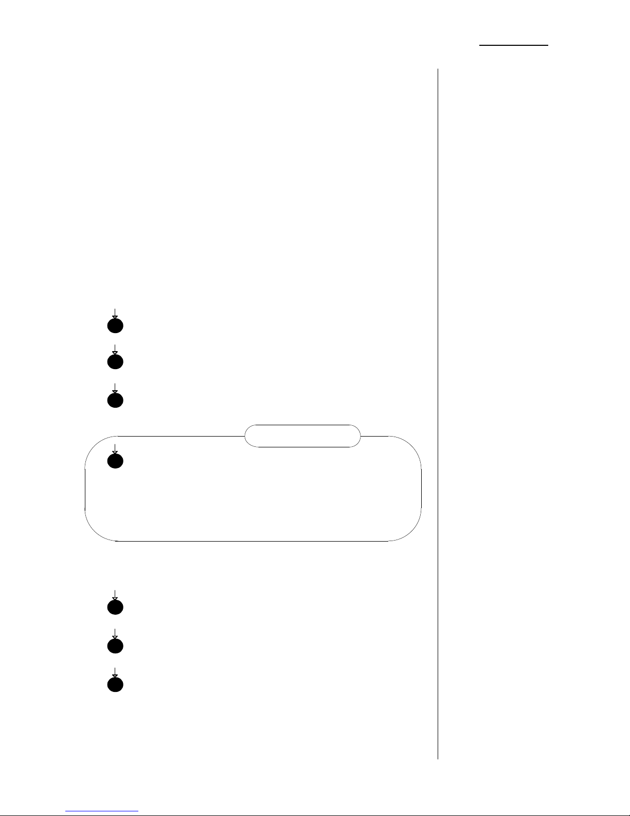
MODE Selection of MAINMENU
SNAP SHOT Selection of SNAPSHOT MENU
CAPT ON CAPTURE button activated
Red LED in CAPTURE button blinks!
CAPTURE Storing (freeze) of actual equaliser
parameter set with present timecode into
EDL, arranged by timecode value
automatically
display: CAPTURE OK!
Note: All snapshots in the EDL will be arranged by time code automatically.
The record of a new take will be inserted in the EDL in order of stored
timecode values automatically.
MODE Selection of MAINMENU
SNAP SHOT Selection of SNAPSHOT MENU
CAPT OFF CAPTURE button disactivated
Red LED in CAPTURE button is erased!
Capture mode is disactivated automatically by switching power off.
(Capture mode is not stored for restart of the unit.)
4.7
SNAPSHOT
AUTOMATION
GENERATING
SNAPSHOTS BY
CAPTURE MODE
(only working
with timecode!)
DISACTIVATING
CAPTURE MODE
push
push
push
push
push
push
push
CAPTURE mode
Page 20
4. OPERATION
19
MODE Selection of MAINMENU
SNAP SHOT Selection of SNAPSHOT MENU
edit Selection of EDIT MODE
display: SNAPSHOT etr new hh:mm:ss:FF
hh (h-mid FREQ) Selection of hours value
mm (h-mid WIDTH) Selection of minutes value
ss (h-mid RANGE) Selection of seconds value
ff (high FREQ)Selection of frames value
Note: Caused by arrangement of snapshots by time code it is necessary to
create different timecode values for each snapshot, even if EDL is only used
as event list (playback without timecode, see: playback EDL without
timecode)!
To place a new snapshot or to replace an existing snapshot at a defined
position the timecode value is to be set between the timecode values of
snapshot before and snapshot behind.
ETR Saving the generated timecode and
(low FREQ) switching to filter parameter setting
display: edit ** and filter parameter set
[** snapshot no.]
adjustment of filter parameter like described in 4.1 - 4.3
MODE Saving created snapshot and
selection of snapshot EDIT MODE
display: snapshot etr ** edit hh:mm:ss:ff del
[** number of last snapshot in EDL]
more editing of snapshots or (selection by turning low RANGE)
or
MODE Selection of SNAPSHOT MENU
MODE Selection of MAIN MENU
SNAP SHOT Selection of SNAPSHOT MENU
edit Selection of EDIT MODE
display: SNAPSHOT new hh:mm:ss:FF
CREATING
SNAPSHOTS BY
EDIT MODE
DEFINED
PLACEMENT AND
INSERTION OF
SNAPSHOTS
EDITING OF FILTER
PARAMETER
EDITING
SNAPSHOTS BY
EDIT MODE
push
push
push
push
push
push
push
push
turn
push
Page 21
4. OPERATION
20
new snapshot selection for editing
(low RANGE) (only selectable if EDL is not empty)
display: 01 ... 50 selection of snapshot 01 ... 50 for editing
hh (h-mid FREQ) Adjustment of hours value
mm (h-mid WIDTH) Adjustment of minutes value
ss (h-mid RANGE) Adjustment of seconds value
ff (high FREQ)Adjustment of frames value
Note: Caused by arrangement of snapshots by time code it is necessary to
create different timecode values for each snapshot, even if EDL is only used
as event list (playback without timecode, see: playback EDL without
timecode)!
To place a new snapshot or to replace an existing snapshot at a
defined position the timecode value is to be set between the timecode
values of snapshot before and snapshot behind.
edit Recall of filter parameter set for
(l-mid WIDTH) sound rehearsal and on-line editing
display: edit ** and filter parameter set
[** snapshot no.]
readjustment of filter parameter like described in 4.1 - 4.3
MODE Saving of edited filter parameter and
return to SNAPSHOT EDIT MENU
ENTER Saving the edited snapshot and return to
(low FREQ) SNAPSHOT MENU
display: snapshot SNAPSHOT MENU
or
del (high RANGE) Deleting the selected snapshot and return to
SNAPSHOT MENU
display: snapshot SNAPSHOT MENU
or
MODE Return to SNAPSHOT MENU without
saving
display: snapshot SNAPSHOT MENU
to escape snapshot menu
MODE Selection of working mode
EDITING OF
TIMECODE
PARAMETER
DEFINED
PLACEMENT AND
INSERTION OF
SNAPSHOTS
RECALL AND
EDITING OF FILTER
PARAMETER
SAVING EDITED
SNAPSHOT
DELETING OF
SNAPSHOTS
push
push
push
push
turn
push
push
turn
Page 22
4. OPERATION
21
MODE Selection of MAINMENU
SNAP SHOT Selection of SNAPSHOT MENU
edit Selection of EDIT MODE
display: SNAPSHOT etr new hh:mm:ss:FF
new snapshot selection for copy
(low RANGE) (only selectable if EDL is not empty)
display: 01 ... 50 for selected snapshot
edit loading filter parameter set of selected
snapshot as active parameter set for
sound rehearsal and for copy
display: edit <snapshot no> <filter parameter>
MODE Selection of SNAPSHOT EDIT MENU
01..50 Selection of NEW snapshot, turn knob until
(low RANGE) new is displayed
display: SNAPSHOT new hh:mm:ss:FF
hh (h-mid FREQ) Selection of hours value
mm (h-mid WIDTH) Selection of minutes value
ss (h-mid RANGE) Selection of seconds value
ff (high FREQ)Selection of frames value
Note: Caused by arrangement of snapshots by time code it is necessary to
create different timecode values for each snapshot, even if EDL is only used
as event list (playback without timecode, see: playback EDL without
timecode)!
To place a new snapshot or to replace an existing snapshot at a defined
position the timecode value is to be set between the timecode values of
snapshot before and snapshot behind.
ETR Saving loaded filter parameter and
timecode
(low FREQ) as new snapshot
display: edit ** and filter parameter set
[** snapshot no.]
MODE Return to SNAPSHOT EDIT MENU
more editing or
MODE Return to SNAPSHOT MENU
COPYING
SNAPSHOTS BY
EDIT MODE
RECALL OF FILTER
PARAMETER
EDITING OF
TIMECODE
PARAMETER
DEFINED
PLACEMENT AND
INSERTION OF
SNAPSHOTS (COPY)
push
push
turn
push
push
push
push
push
turn
turn
push
Page 23
4. OPERATION
22
MODE Selection of MAINMENU
SNAP SHOT Selection of SNAPSHOT MENU
PLAY Selection of PLAY MODE
display: play xx and equaliser parameter display
[xx -snapshot number]
No parameter is adjustable!
Takes are recalled following timecode automatically.
to escape PLAY MODE
MODE Selection of working mode
MODE Selection of MAINMENU
SNAP SHOT Selection of SNAPSHOT MENU
PLAY Selection of PLAY MODE
display: play xx and equaliser parameter display
[xx - snapshot number]
No parameter is adjustable!
Takes are recalled manually.
CAPTURE manual recall of next snapshot
(one step forward)
A/B manual recall of previous snapshot
(one step backward)
to escape PLAY MODE
MODE Selection of working mode
The playback stepwise can be controlled remotely using GPI remote control.
See also 4.9 Remote operation - GPI control!
PLAYBACK AN
EDL BY
PLAY MODE
(with timecode
= autoplay)
PLAYBACK AN
EDL STEPWISE
(only working
without timecode)
push
push
push
push
push
push
push
push
push
push
Page 24
4. OPERATION
23
MODE Selection of MAINMENU
SNAP SHOT Selection of SNAPSHOT MENU
clear Selection of PLAY MODE
display: takelist clr? Yes no
yes Clearing the EDL
Attention! No undo possible.
no Escaping clearing mode without delete.
Selection of working mode.
CLEARING AN
EDL
push
push
push
push
push
Page 25
4. OPERATION
24
The digital filter processor e07 can be used in stereo or in 2channel mode. Changing of the channel mode requires
rebooting of the unit.
In stereo mode all parameters are the same for left and for right
channel. The limiter is working in linked mode. All functions are
available.
In 2-channel mode all parameters can be different for each of
the two channels. The limiter is working unlinked. Dynamic
equaliser is not working in 2-channel mode.
A/B comparison is available for two pairs of L/R parameter sets
L/R parameter sets are storable in presets.
display above L/R button L 2-ch mode, left channel selected
R 2-ch mode, right channel selected
blank stereo mode
MODE Selection of MAINMENU
UTIL Selection of UTILITY menu
2-CH Selection of 2-channel mode
or
st Selection of stereo mode
L/R switching between left and right channel
display: L (if left channel is selected)
R (if right channel is selected)
Note:
Changing of the channel mode requires rebooting of the unit.
After changing the channel mode A and B memory are cleared
and loaded with default adjustments.
Loading of presets stored originally in another channel mode is
not possible.
Loading of EDL created originally in another channel mode is
not possible.
SELECTION OF
2-CHANNEL
MODE
4.8
UTILITIES
STATUS DISPLAY
MODE SETTING
push
2-channel mode
push
push
push
push
Page 26
4. OPERATION
25
For setting of sort of timecode, which is used for snapshot
automation.
(Timecodes are different regarding resolution in frames. Framing can be set
by this utility function.)
MODE Selection of MAINMENU
UTIL Selection of UTILITY menu
time code Selection of timecode setting
display: time code act: <frame stat> 24 f 25 f 30 f
<frame stat>: actual frame setting
24 F = 24 frames per second
25 F = 25 frames per second
30 F = 30 frames per second
24 f Selection of 24 frames per second
25 f Selection of 25 frames per second
30 f Selection of 30 frames per second
SELECTION OF
TIMECODE
push
push
push
push
push
push
Page 27
4. OPERATION
26
Channel status bits are defined in the AES/EBU data stream .
With the digital filter processor e07 it is possible to transmit this
information without changing or to set these information
defined.
(Sometimes it is helpful to change the channel status, f.i. if following units
don’t want to accept incoming signals.)
MODE Selection of MAINMENU
UTIL Selection of UTILITY menu
chan stat Selection of channel status setting
display: channel stat act: <chan stat> cons prof trns
<chan stat>: actual channel status setting
cons = consumer status
prof = professional status
trns = transparent (input = output)
cons Selection of consumer mode
prof Selection of professional mode
trns Selection of transparent mode
SELECTION OF
CHANNEL
STATUS
push
push
push
push
push
push
Page 28
4. OPERATION
27
DATA SAVE is a function for saving and restoring existing preset data and
editlist by using external storage devices. All data will be transferred via
AES/EBU interface. It is possible to use all storage medias which can be
connected via AES/EBU and which don’t change or manipulate audio data of
AES/EBU signal (f.i. DAT, audio file on workstation). The data block has a
duration of appr. 10 seconds. The header of data dump block is containing
number and name of data block. This is to be used to address determined
data block for saving or loading.
MODE Selection of MAINMENU
UTIL Selection of UTILITY menu
DATA Selection of DATA SAVE menu
save edl Selection of data saving mode
display: name edl nrxx e d i t l i s t
xx Selection of data block (EDL) number for
(FREQ low section) data saving (01...99)
ALL KNOBS Changing of the default name (EDITLIST)
(low RANGE into an individual name (10 digits), push to
... output GAIN) generate space
or proceed without name changing (use of default name).
Start record function of connected external storage device (f.i.
DAT recorder)
FREQ/ENTER Saving of data block
(low section)
display: save edl nr** < name >
After appr. 10 seconds data saving is finished. The unit returns
automatically to normal working mode. Then you can stop
recording of data at external storage device.
DATA SAVE
SAVING
PRESET AND EDL
DATA
push
push
push
push
turn
push
turn
Page 29
4. OPERATION
28
MODE Selection of MAINMENU
UTIL Selection of UTILITY menu
Data Selection of DATA SAVE menu
nrxx Selection of data block (EDL) for loading
LOAD edl Selection of data loading mode
Starting of external storage device which is connected to the
AES/EBU input and which is playing back formerly saved data.
display: load edl nr++ nr** < name >
++ - number of selected data block
** - number of actual running data block
<name > - name of actual running data
block
The unit is detecting the selected data block automatically. It is
loading the selected data block automatically.
display: load edl nr++ o.k.
++ - number of loaded data block
After a few seconds the unit returns automatically to normal
working mode. Then you can stop playback of data at external
storage device.
LOADING
PRESET AND EDL
DATA
push
push
push
turn
push
Page 30
4. OPERATION
29
MODE Selection of MAINMENU
UTIL Selection of UTILITY menu
DATA Selection of DATA SAVE menu
SHOW edl Selection of data block showing mode
Starting of external storage device which is connected to the
AES/EBU input and which is playing back formerly saved data.
The unit is detecting actual running data blocks automatically.
display: show edl nr** < name >
** - number of actual running data block
<name > - name of actual running data
block
To escape EDL SHOW mode
MODE Return to normal working mode
SHOWING
NUMBER AND
NAME
OF STORED
DATA BLOCK
push
push
push
push
push
Page 31
4. OPERATION
30
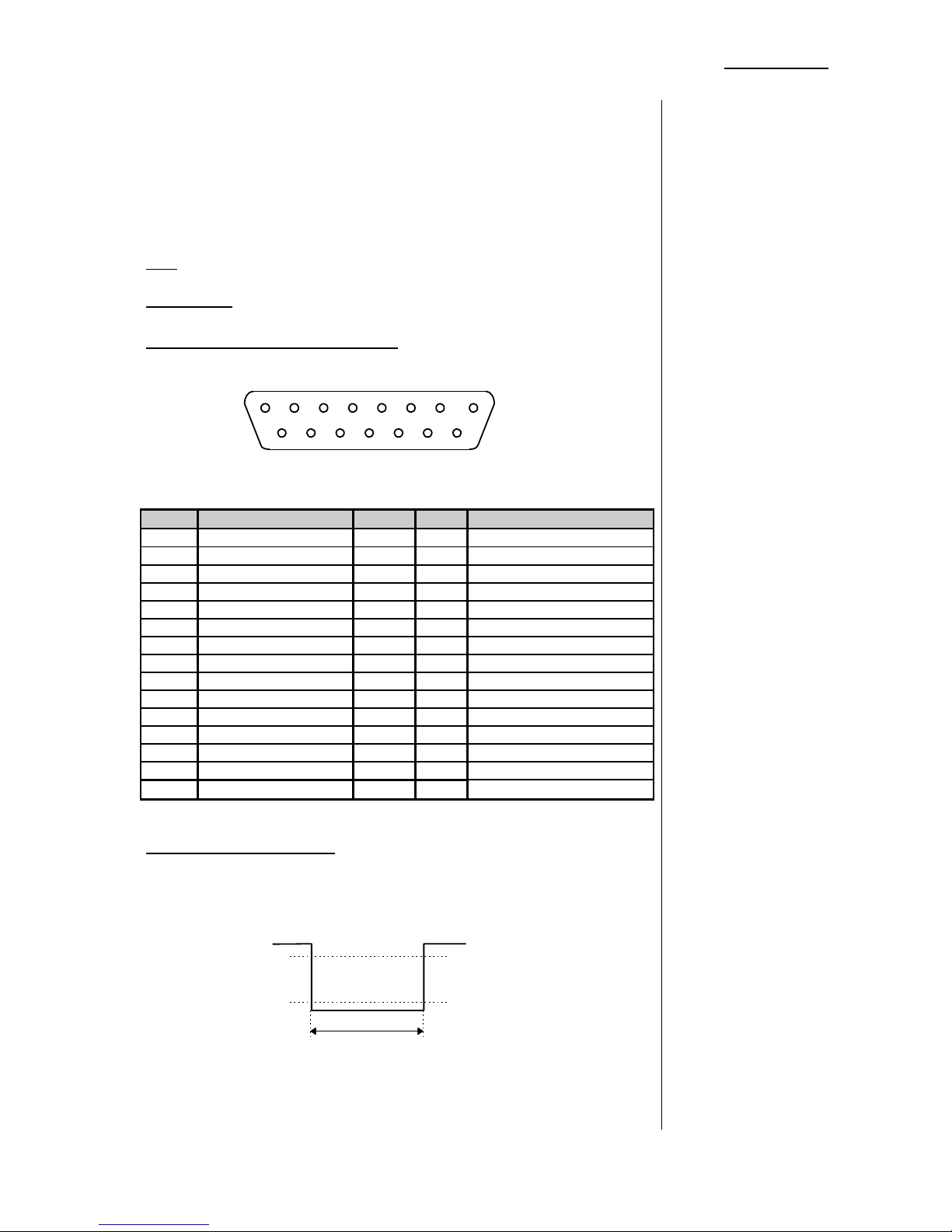
The digital filter processor e07 can be remote controlled by GPI
control.
Use: Control from other remote controls
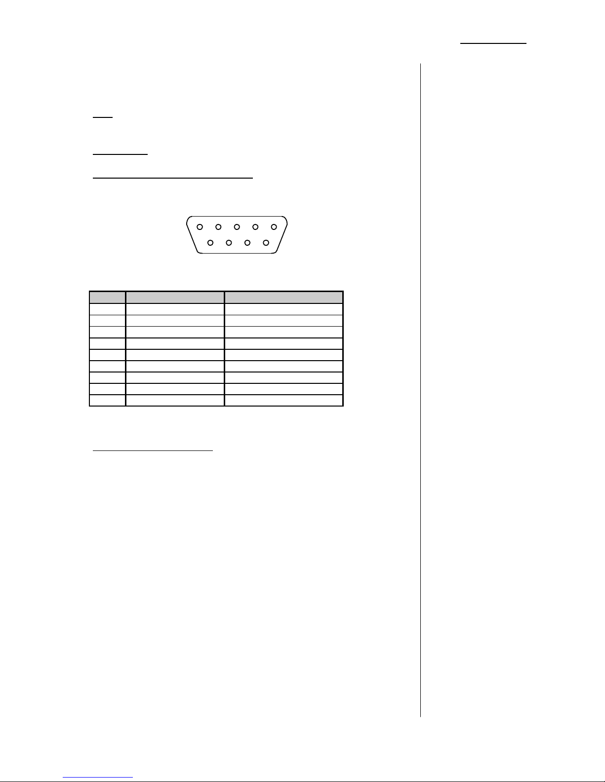
Connector: D-SUB 15pin
Pin assignment of the connector
8 1
15 9
Pin Signal name Logic I/O Functions
1 GND GND
2 RESET L I reset EDL to take 01
3 UP L I next EDL take
4 DOWN L I previous EDL take
5 BYPASS L I general bypass
6 CAPTURE L I captures snapshot+LTC
7 reserved
8 not used
9 not used
10 not used
11 not used
12 not used
13 not used
14 not used
15 not used
Electrical specifications:
Command input Level L: 1,5V or less, 50ms or more
Level H: 3,5V or more
50 ms; or more
+1,5V
+3,5V
Pulse signals
4.9
REMOTE
CONTROL
GPI REMOTE
CONTROL
(15 PIN
PARALLEL
REMOTE)
Page 32
4. OPERATION
31
The digital filter processor e07 can be remote controlled by
serial remote control (RS-232).
Use: Control from the personal computer
Control from other remote controls
Connector: D-SUB 9pin
Pin assignment of the connector
5 1
9 6
Pin Signal name Functions
1 not used
2 TXD Transmit data
3 RXD Receive data
4 not used
5 GND GND
6 DSR Data set ready
7 not used
8 DTR Data terminal ready
9 not used
Electrical specifications:
Command input ON: +5V or more
OFF: -5V or less
SERIAL REMOTE
CONTROL
(RS-232)
Page 33
32
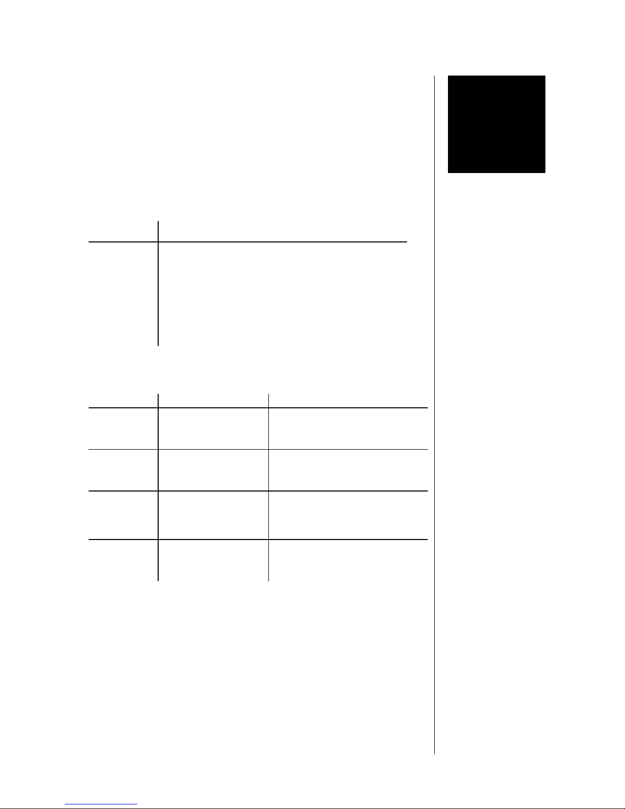
BOOT DISPLAY AND
TROUBLE SHOOTING
display meaning/explanation
DIGITAL EQ
display of unit type part one
JÜNGER E07
display of unit type part two
VERSION E07
C:x.x E: y.y
display of loaded software versions
x.x and y.y
display error/message remedies
NO SYNC
no sync at digital input n connect the digital input with
valid input signal
NO timecode
no timecode at
timecode input
n connect the timecode input
with valid LTC input signal
NO data
empty preset, no data
stored before
n use another preset for loading
parameter
ERROR 1...5
error level 1..5 n switch power off, reboot the
unit by switching power on
5.1
BOOT DISPLAY
5.2
ERROR DISPLAY
AND TROUBLE
SHOOTING
5
Page 34

33
APPLICATION NOTES
Reputation has it that digital filters sound hard and metallic, that
there is no warmth and clarity and the dynamic and stereo
imaging is flat. Many sound engineers consider that "high
quality analogue filters simply sound better". The difference
between analogue and traditional digital filters is, in the final
analysis, related to the frequency range of the filters. The
frequency range is clearly wider in the case of analogue filters
than the traditional digital filter which is sharply limited to half of
the sampling rate of 40 or 50 kHz, ie. around 22kHz. As a result,
non-linearities in amplitude and phase characteristics occur well
before the cut-off frequency which lead to coloration at high
audio frequencies.
In order to implement a digital filter whose sound qualities are
comparable with a good analogue filter, the corresponding
transmission characteristics must be designed in digital form.
High quality digital filters should sound as good at high
frequencies as good analogue filters and in order to achieve this
a higher sampling frequency is required. The distortion of the
frequency axis is reduced the higher the sampling rate becomes
relative to the audio range.
The Jünger Audio digital filter processor Model e07 works
internally at twice the sampling rate of the input signal and can
therefore provide filtering up to around 40kHz moving any
distortion of the signal away from the audio spectrum. This
results in a much cleaner audio signal. Listening tests show
remarkable results with a more realistic and "authoritative"
sound. Stereo imaging is preserved and reverberation decays
naturally without any "metallic" components. This situation can
be proved technically by measuring the results which clearly
show an improvement at higher frequencies together with
improved phase characteristics.
6.1
DIGITAL FILTER
AT 96 KHZ
6
Page 35
6. APPLICATION NOTES
34
In dynamic mode the filter activity is controlled by the audio
level. The filter get active only if the level of incoming audio
signal reaches a defined threshold level. A typical application for
a dynamic equaliser is the de-esser function.
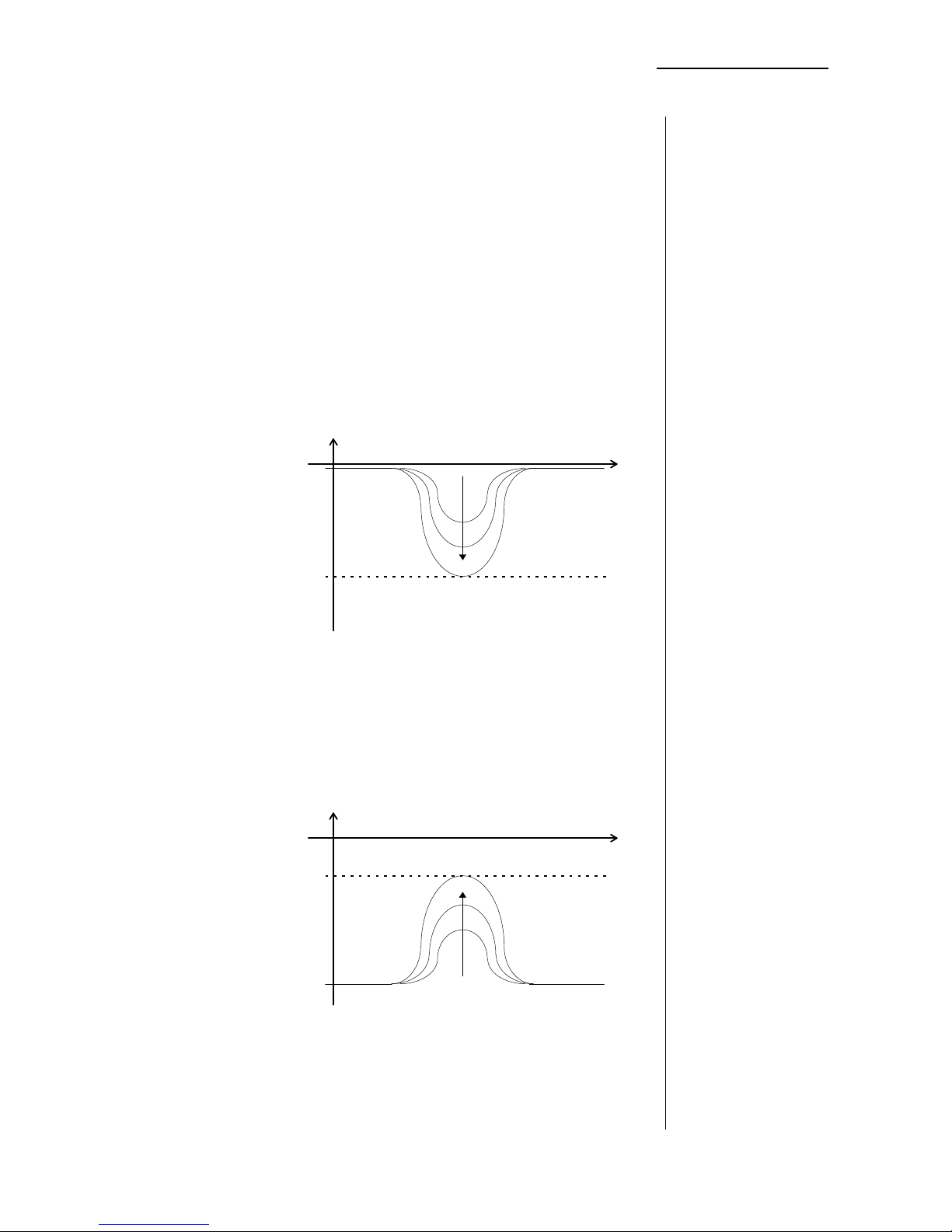
There are two basic modes for the dynamic equaliser,
dependent on adjusted RANGE value.
Negative values for RANGE (cut function) switches into
REDUCE mode. In REDUCE mode signals will be reduced if
their level is higher as the threshold level.
All spectral parts of the signal (filtered by the filter band) which
has more level as the adjusted threshold level will be reduced by
the RANGE value. The level reduction never comes below the
threshold level.
threshold
REDUCE MODE
RANGE value negative (cut)
frequency
level
Positive values for RANGE (boost function) switches into
ENHANCE mode. In ENHANCE mode signals will be increased
(or enhanced) if their level is below the threshold level.
All spectral parts of the signal (filtered by the filter band) which
has less level as the adjusted threshold level will be increased
by the RANGE value. The increased level never comes over the
threshold level.
ENHANCE MODE
RANGE value positive (boost)
threshold
frequency
level
6.2
DYNAMIC
EQUALISER
Page 36
6. APPLICATION NOTES
35
The activity of the filter is displayed by a bargraph above
RANGE knob.The intensity of the bar shows the activity of the
filter, dependent on signal level and RANGE adjustment.
REDUCE (CUT)
BARGRAPH DISPLAY
ENHANCE (BOOST)
Caused by the limited DSP power of the unit two bands can be
switched as dynamic equaliser at the same time only. The other
bands can be used as normal equaliser bands. All equaliser
bands are calculated at doubled sample rate or 96 kHz.
In 2-channel mode dynamic equaliser function is not available.
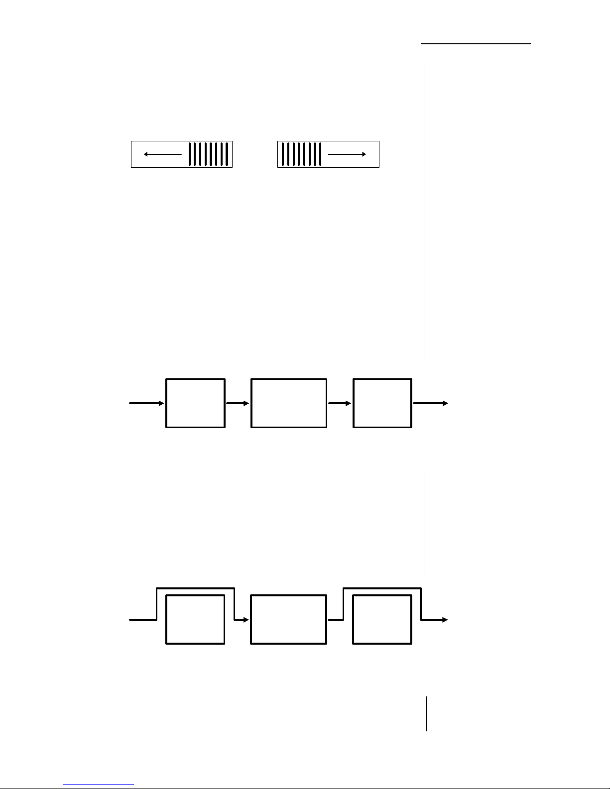
The Digital Filter Processor e07 is working internaly with
doubled sample rate. That means that the filter calculation is
proceed at doubled sample rate of the input signal (88.2 kHz for
44.1 kHz input or 96 kHz for 48 kHz input).
INPUT
SIGNAL
OUTPUT
SIGNAL
DOUBLED
SAMPLE RATE
NORMAL
SAMPLE RATE
NORMAL
SAMPLE RATE
UP
SAMPLER
EQUALISER
PROCESSING
DOWN
SAMPLER
The unit is prepared for operation with high sampling signals at
96kHz.
In case of connection with high sampling signal sources the unit
switches automatically into HIGH SAMPLING MODE. All
operations will proceed at 96 kHz and high sampling signal is
feed to the output of the unit.
INPUT
SIGNAL
OUTPUT
SIGNAL
HIGH
SAMPLE RATE
HIGH
SAMPLE RATE
HIGH
SAMPLE RATE
UP
SAMPLER
EQUALISER
PROCESSING
DOWN
SAMPLER
It is not possible to convert the sample rate between input and
output of the unit in any direction.
6.3
HIGH SAMPLING
MODE
Page 37
6. APPLICATION NOTES
36
The audio signal delay through the digital filter processor is
approx. 2ms due to delaying of the audio signal using
internal memory. A small delay is deliberately introduced to the
audio signal in order to allow limiter and filter algorithms which
can 'preview' the audio signal before changing it.
This delay must be considered before attempting to mix
signals processed by the dynamics processor with other
undelayed signals.
When mixing together a delayed signal and a direct signal
there may be cancellation of the signal waveform at some
frequencies and re-inforcement of the waveform at other
frequencies (comb filter effect). Corresponding 2ms delay of
direct signals should therefore be carried out before mixing
them with delayed processed signals.
6.4
INFLUENCE OF
SIGNAL DELAY
TIME
Page 38
7. TECHNICAL SPECIFICATIONS
37
TECHNICAL
SPECIFICATIONS
sampling rate : 44.1 kHz ... 96 kHz
audio data format : 24-bit (AES/EBU and S/PDIF)
AES/EBU
level : 5 Vpp / 110 Ohm, balanced
connector : XLR
input format : AES professional, AES consumer
output format : same as input
SPDIF
level : 0.5 Vpp/ 75 Ohm, unbalanced
connector : RCA
input format : AES professional, AES consumer
output format : same as input
static or dynamic filter mode for each band selectable
OFF switches for each band
overall bypass
low cut filter frequency range 2 Hz ... 120 Hz
-6, -12, -18 dB per octave
high cut filter frequency range 2 kHz ... 20 kHz
-6, -12, -18 dB per octave
low filter frequency range 20 Hz ... 500 Hz
-15 ...+15 dB boost or cut
shelving characteristic
l-mid filter frequency range 50 Hz ... 20 kHz
(mid1) -15 ...+15 dB boost or cut
shelving characteristic
h-mid filter frequency range 50 Hz ... 20 kHz
(mid2) -15 ...+15 dB boost or cut
shelving characteristic
high filter frequency range 2 kHz ... 20 kHz
-15 ...+15 dB boost or cut
shelving characteristic
dynamic mode threshold 0 ... -50 dBFS
-15 ... +15 dB enhancement or reducement
bar-graph indicates dynamic activity
digital
input / output
filter
7
Page 39
7. TECHNICAL SPECIFICATIONS
38
output gain -15 ... +15 dB, resolution 0.1 dB
digital limiter threshold 0 dBFS, fixed
attack and release times adaptive controlled
by the program signal
(program signal dependent)
time code LTC
level > -10 dBu
connector: XLR
10 kOhm, balanced
serial remote RS-232
TTL level, 9 pin SUB D
GPI TTL level, 15 pin SUB D
power supply IEC mains input socket
AC 25 VA 230 V, 50 Hz (EU version)
240 V, 50 Hz (UK version)
100 V, 60 Hz (JP version)
127 V, 60 Hz (US version)
size 482 mm x 44 mm x 251 mm
(19“, 1 RU)
weight appr. 5 kg
output
timecode input
remote
general
Page 40
39
WARRANTY AND SERVICE
INFORMATION
JÜNGER AUDIO grants a two-year warranty on the
digital filter processor MODEL e07
If the unit has to be serviced, please send it, ideally in the
original box, to:
JÜNGER AUDIO - Studiotechnik GmbH
Rudower Chaussee 5 (Geb. 9.51)
D - 12489 Berlin
GERMANY
Tel.: (*49) -30-677721-0
Fax.: (*49) -30-677721-46
8
 Loading...