

Page 1
Page 2

Page 3

Page 4

DAP4-VAP_manual_EN_161219.doc
D*AP4 VAP
Hardware Features
•
1RU compact 19" processing device with front side info display
• Dual power supply second power supply for redundancy
• Front panel info display for signal activity, IP address, status alert
• Remote Panel optional X*AP RM1 panel
• Optional mic inputs optional dual high end mic preamp module with phantom power
• Optional AES42 input optional module for digital mic / line input
• Balanced AES I/O AES line input / output for desk inserts or program input
• One interface slot I/O expansion slot for one option board
• 3G / HD / SD SDI module option board with SDI de-embedder / embedder and relay bypass
• 4x AES I/O module option board with 4x AES3id I/Os and relay bypass
• 4Ch analog I/O module option board with 4 analog line I/Os and relay bypass
• RJ45 network connector 100BaseT full duplex Ethernet interface
• USB B connector built in USB < > serial adapter to access the device service port
• 8 GPI/Os 8 balanced inputs, 8 relay closure on 25pin Sub-D
• Aux power supply isolated 5V supply for external wiring
• External sync IN 75Ohm input (Word Clock, AES, Black Burst, Tri-Level)
• Sync OUT 75Ohm Word Clock output
Software Features
•
2
main processing channels chain of processing blocks, mono / stereo operation
• AUX program path extra 2Ch input for a program signal
• Input stage mute, gain, polarity, HPF, LPF
• M/S matrix encode, stereo width, decode
• Phase Rotator corrects imbalanced waveforms
• De-esser frequency, range, type, Q
• Filter spectral signature & 5x full parametric EQs
• Dynamics expander, upward compressor, downward compressor, soft limiter
• Leveler automatic level control for the voice channel
• Voice over stereo or mono voice over extra program input, pan
• LevelMagic™ processor for the program (AUX) path
• Output stage true peak limiter, mute, attenuation
• Monitor output extra feed from the DSP to monitor DSP processing blocks
• SNMP agent SNMP v1, see D*AP4 VAP-MIB
• Remote control l-s-b EmBER plus protocol for VSM integration, 3rd party API
• Mobile user interface graphical operator UI optimized for use on mobile devices
Operating Manual
Page 5

D*AP4 VAP
1
Content
page
Introduction …………………………………………………………………………………………. 3
D*AP4 VAP front panel view ……………………………………………………………………… 4
D*AP4 VAP rear view ……………………………………………………………………………… 4
Block Diagram ………………………………………………………………………………………. 5
Audio Processing Blocks …………………………………………………………………………. 5
Control, Operating & Event Concept …………………………………………………………….. 6
Getting Started – quick start guide ……………………………………………………………….. 7
Getting Started – IP setup in general ……………………………………………………………. 7
Getting Started – IP setup – via console interface …………………………………………… 7
Getting Started – IP setup – via web browser ………………………………………………… 9
Operating – menu structure of the X*AP remote panel – power up display ………………. 10
Operating – menu structure of the X*AP remote panel – operating displays ……………… 11
Operating – menu structure of the X*AP remote panel – menu tree ……………………….. 13
Setup GUI – connecting with the D*AP4 unit – AUDIO PROCESSOR – Overview ………. 14
Setup GUI – SYSTEM – System Status ………………………………………………………… 15
Setup GUI – SYSTEM – Overview ……………………………………………………………… 16
Setup GUI – SYSTEM – Admin ………………………………………………………………….. 16
Setup GUI – SYSTEM – Setup ………………………………………………………………….. 18
Setup GUI – SYSTEM – Remote Access – X*AP Remote ……………………………………. 19
Setup GUI – SYSTEM – Remote Access – Mobile UI …………………………………………. 21
Setup GUI – SYSTEM – the preset concept in detail …………………………………………. 22
Setup GUI – SYSTEM – Preset Cleanup ……………………………………………………….. 22
Setup GUI – SYSTEM – SNMP …………………………………………………………………… 23
Setup GUI – SYSTEM – Backup / Restore ……………………………………………………. 24
Setup GUI – SYSTEM – Firmware Update …………………………………………………….. 25
Setup GUI – SYSTEM – Reboot …………………………………………………………………. 26
Setup GUI – INTERFACES – AES I/O …………………………………………………………… 27
Setup GUI – INTERFACES – Analog Mic ……………………………………………………… 28
Setup GUI – INTERFACES – SDI I/O Interface – Overview ……………………………........ 29
Setup GUI – INTERFACES – SDI I/O Interface – Local Routing ……………………............ 30
Setup GUI – INTERFACES – SDI I/O Interface – Setup ……………………………………… 31
Setup GUI – INTERFACES – SDI I/O Interface – De-Embedder ……………………………. 31
Setup GUI – INTERFACES – SDI I/O Interface – Embedder ……………………………....... 32
Setup GUI – INTERFACES – SDI I/O Interface – MADI Interface – Status / Setup ……..... 33
Setup GUI – INTERFACES – SDI I/O Interface – MADI Interface – Local Routing ……..... 34
Setup GUI – INTERFACES – DANTE I/O interface – Status ………………………………….. 35
Setup GUI – INTERFACES – DANTE I/O interface – Inputs ………………………………….. 37
Setup GUI – INTERFACES – DANTE I/O interface – Outputs ……………………………….. 38
Setup GUI – INTERFACES – DANTE I/O interface – Network ………………………………. 38
Setup GUI – INTERFACES – 4 Ch Analog I/O Interface ……………………………………. 40
Setup GUI – INTERFACES – AES Interface – Status / Setup ..……………………………… 41
Setup GUI – ROUTING ……………………………………………………………………………. 40
Setup GUI – AUDIO PROCESSOR – Overview ……………………………………………….. 43
Setup GUI – AUDIO PROCESSOR – Setup ……………………………………………………. 45
Setup GUI – AUDIO PROCESSOR – Input ……………………………................................. 45
Setup GUI – AUDIO PROCESSOR
– M/S ……………………………………………………… 46
Setup GUI – AUDIO PROCESSOR – Phase Rotator .......................................................... 46
Setup GUI – AUDIO PROCESSOR – De-Esser .………………………………………………. 47
Setup GUI – AUDIO PROCESSOR – Filter – Spectral Signature …………........................ 48
Setup GUI – AUDIO PROCESSOR – Filter – Equalizer ………………………………………. 51
Setup GUI – AUDIO PROCESSOR – Dynamics ………………………………………………. 53
Setup GUI – AUDIO PROCESSOR – Leveler …………………………………………………. 56
Setup GUI – AUDIO PROCESSOR – Voice Over …………………………………………….. 60
Setup GUI – AUDIO PROCESSOR – Level Magic ……………………………………………. 61
Setup GUI – AUDIO PROCESSOR – Output ………………………………………………….. 62
Setup GUI – AUDIO PROCESSOR – Monitor …………………………………………………. 63
Setup GUI – AUDIO PROCESSOR – On Air / Mobile UI …………………………………….. 64
Page 6

D*AP4 VAP
2
Content
page
Setup GUI – MEASUREMENT – Loudness ……………………………………………………. 66
Setup GUI – EVENTS – Overview ………………………………………………………………. 67
Setup GUI – EVENTS – Triggers – Sources – Remote Hotkeys ……………………………. 68
Setup GUI – EVENTS – Triggers – Sources – Network ……………………………………… 69
Setup GUI – EVENTS – Triggers – Sources – Parameters ………………………………….. 69
Setup GUI – EVENTS – Triggers – Configuration – Trigger Equation ……………………… 70
Setup GUI – EVENTS – Events
–
Preset Events (Profiles)
………………………………
68
Setup GUI – EVENTS – Events
–
Parameter Events
………………………………….....
71
Setup GUI – EVENTS – Events – Measurement Events
…………………………………
73
Setup GUI – EVENTS – Events – I/O Events ………………………………………………….. 73
Setup GUI – EVENTS – Events – Bypass Events …………………………………………….. 74
Setup GUI – EVENTS – Actions – Event Actions …………………………………………….. 74
Setup GUI – EVENTS – Actions – Bypass Actions …………………………………………... 75
Technical Data – 2 Channel Voice Audio Processor Edition [D*AP4 VAP EDITION] ……… 76
Technical Data – Option Board SDI I/O (3G/HD/SD) [O_DAP_SDI_a] ……………………… 77
Technical Data – Option Board Analog Line-In and/or Mic-In [O_DAP_AMIC_a] ………….. 78
Technical Data – Option Board Analog Out [O_DAP_8DA_a] ………………………….......... 79
Technical Data – Option Board Analog I/O [O_DAP_ADDA_a] …………………………....... 79
Technical Data – Option Board AES/EBU I/O [O_DAP_AES_a] …………………………….. 80
Technical Data – Option Board MADI I/O, BNC [O_DAP_MB_a] ……………………………. 81
Technical Data – Option Board MADI I/O, Optical [O_DAP_MO_MM_a] ............................. 81
Technical Data – Option Board MADI I/O, Optical [O_DAP_MO_SM_a] ……………………. 81
Technical Data – Option Board Audio-over-IP DANTE™ I/O [O_DAP_DANTE_a] ………... 82
Technical Data – Rear Connectors – pin assignment ……………………………………….. 83
Technical Data – Optional Interface Modules – pin assignment ……………………………. 84
Technical Data – GPI wiring ……………………………………………………………………… 85
Safety Information …..……………………………………………………………………………. 86
Warranty …………………………………………………………………………………………….. 86
Page 7

D*AP4 VAP
3
Introduction
Primarily designed to apply individual processing to voice based applications the 2 channel D*AP4 VAP
toolset includes HP/LP filtering, dynamic section, full parametric EQ, and de-essing. A dedicated voice leveler
aids the integration of voice programs into loudness based broadcasting. Targeted at radio stations and TV
production voice-over applications, this unit will make your daily life easier and let you focus on content.
With Spectral Signature™ dynamic EQ, you will have a tool with automatic and dynamic EQ control to
balance spectral differences to one specific voice only when necessary. Spectral Signature™ analyzes
incoming audio and compares the spectral structure with individual predetermined voice “footprints”. On this
basis, dynamic EQ corrections will be applied only when necessary to achieve consistent results. Spectral
Signature™ is a D*AP4 VAP standard feature while a separate program I/O path allows for voice over either
in manual controlled or automatic (ducking) mode.
The D*AP4 VAP offers interfaces to allow integration in existing environments via AES insert or with an
optional analog board adding 2 high quality mic-preamps. Preset management can be controlled via network
integration. The X*AP RM1 provides the ability to control up to 4 units via hardware simultaneously, while
D*AP4 VAP’s network interoperability is designed to allow full integration into broadcast scheduling and
studio management systems. With this feature, preset changes will take place automatically according to
your content schedule.
At the heart of the D*AP4 VAP is a sophisticated audio processor, powered by Analog Devices® Sharc
DSPs. These DSPs provide signal processing, audio delays, monitoring facility as well as level
measurements.
The AES I/Os on the motherboard may be added to by a variety of interface modules that can be installed as
an option into the D*AP4 VAP’s interface slot.
A comprehensive routing matrix allows for almost every combination of audio signal flow from inputs to
outputs.
Routing paths, the enabling and disabling of audio processing blocks and the setting of processing
parameters can be pre configured by individual presets dedicated to each function block. The content of the
presets can be displayed and edited off line while the device is in use. These presets may either be recalled
on demand by the operator via the GUI, the X*AP RM
1
remote panel hot keys or external systems, but may
also be part of complex scenarios defined by the operator and automatically executed by the event manager
of the device.
The D*AP4 VAP provides a web based setup GUI and an X*AP RM
1
remote panel that displays status and
metering information and allows user intervention. Due to the complexity of the device, the features of the
X*AP RM
1
remote panel are limited to operating needs.
Junger Audio’s application manager J*AM is also available as an add on and can be attached by a few
simple clicks to the D*AP4 VAP so that users can display level bar graphs.
The availability of an SNMP agent, which provides traps and status polling rounds up the feature set of the
D*AP4 VAP.
As with most advanced tools, the D*AP4 VAP can be driven in a variety of ways, depending on requirements
and ideas of the user. These can range from the simple and straightforward through to quite complex set
ups.
Although this manual explains the functions and general operation of the D*AP4 VAP, it does not give
detailed scenarios because the operational needs of today's productions vary so widely between
organizations and their work flows and cover so many different parameters – from simple editorial work
places, to complex database driven shift control for multiples of work places, through to semi-automatic
operation controlled by broadcast automation systems.
Junger Audio is more than happy to discuss your particular requirements with you and to convey your ideas
and solutions to other users of the Junger Audio Processors community.
Page 8
D*AP4 VAP
4
D*AP4 VAP front panel view
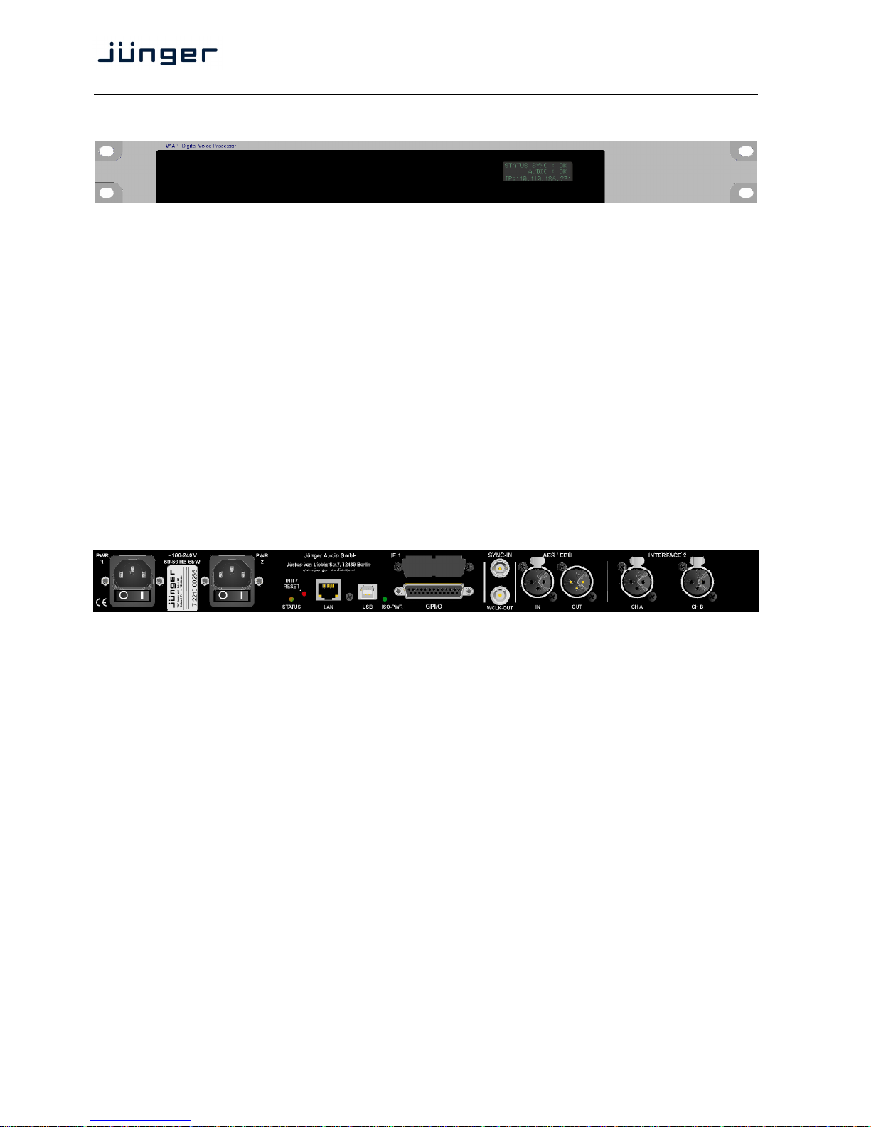
The front panel of the D*AP4 VAP has a 3 line status display and two hidden touch buttons ~ 2.5cm left of the
display. Button 1 = Home will switch back to the power up display no matter which display level you are in.
Button 2 cycles through the multi level display:
Level 1 Power up display [device type / firmware version]
Level 2 Status [OK / Error] / Device Name / IP address
Level 3 IN / OUT peak meter
Level 4 Monitor M1 / M2 peak meter
Level 5 Program Out short term loudness
Level 6 Program Out integrated loudness and integration time
Display background Green = device status OK
color Red = device status ERROR
flashing red / green during boot up
The measures of the loudness displays depend on the setup of the respective loudness mode
(see AUDIO PROCESSOR > SETUP > Loudness Mode).
D*AP4 VAP rear view
For fail safe operation, the D*AP4 VAP provides two independent power supplies. These power supplies
operate in load balance. The status of both PSUs are combined with other status information and displayed
as backlight color of the front panel display.
STATUS shows the status of the device controller
INIT / pressing the INIT button briefly will warm start the device controller.
RESET Holding down the button until the STATUS LED flashes 5 times will initialize the
D*AP4 VAP to factory default
LAN RJ45 socket for Ethernet connection to a LAN
USB USB 2.0 type B socket to connect the built in USB >> serial converter with an
external PC
ISO-PWR lights up if the isolated 5V power supply for GPI /O application is turned on
GPI/O 25pin Sub-D female connector to interface with the 8 optical isolated general
purpose inputs and 8 solid state relay closure outputs
Interface 1 slot to mount one of the optional interface boards (SDI, AES, analog)
SYNC IN 75Ohm BNC connector to connect with external sync sources
WCLK-OUT 75Ohm BNC connector to synchronize external devices to the D*AP4 VAP
internal word clock
AES / EBU IN AES3 input
AES / EBU OUT AES3 output
Interface 2 slot to mount the optional dual high end microphone pre amp module
or the optional dual AES42 module for digital microphones
Page 9
D*AP4 VAP
5
Block Diagram
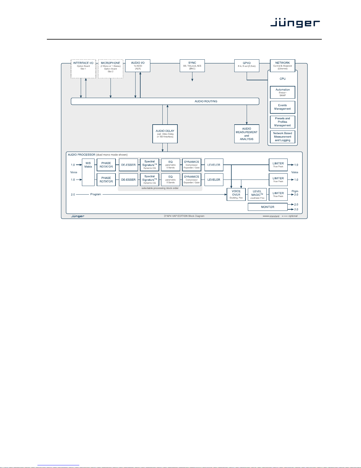
The above schematic shows the principal blocks of the D*AP4 VAP.
The core of the unit is the audio processor with 4 inputs, 4 outputs and a 2ch monitor output.
An AES I/O on the motherboard is provided for digital line operation. The respective connectors have relay
bypass for power fail operation. The bypass ciruit may be disabled by an internal jumper.
An interface slot is provided to carry optional 3G / HD / SD-SDI, AES I/O / MADI / DANTE or even analog
expansion modules. It allows for extremely flexible interfacing of the D*AP4 VAP, especially for video based
voice over applications. The above schematic shows a MADI interface installed.
On the rear righthand side is the location for an optional high end dual microphone pre amp with phantom
power or an alternative optional dual AES42 input module.
The sync. circuit can deal with all formats to integrate the D*AP4 VAP into digital facilities with a sample rate
from 44.1 to 96kHz. Other devices may be synchronized by the word clock output of the D*AP4 VAP.
The D*AP4 VAP has 8 balanced GPIs and 8 relay closure GPO contacts. This enables the user to simply
recall presets or call events, change device configurations and report general status information.
Page 10
D*AP4 VAP
6
Audio Processing Blocks
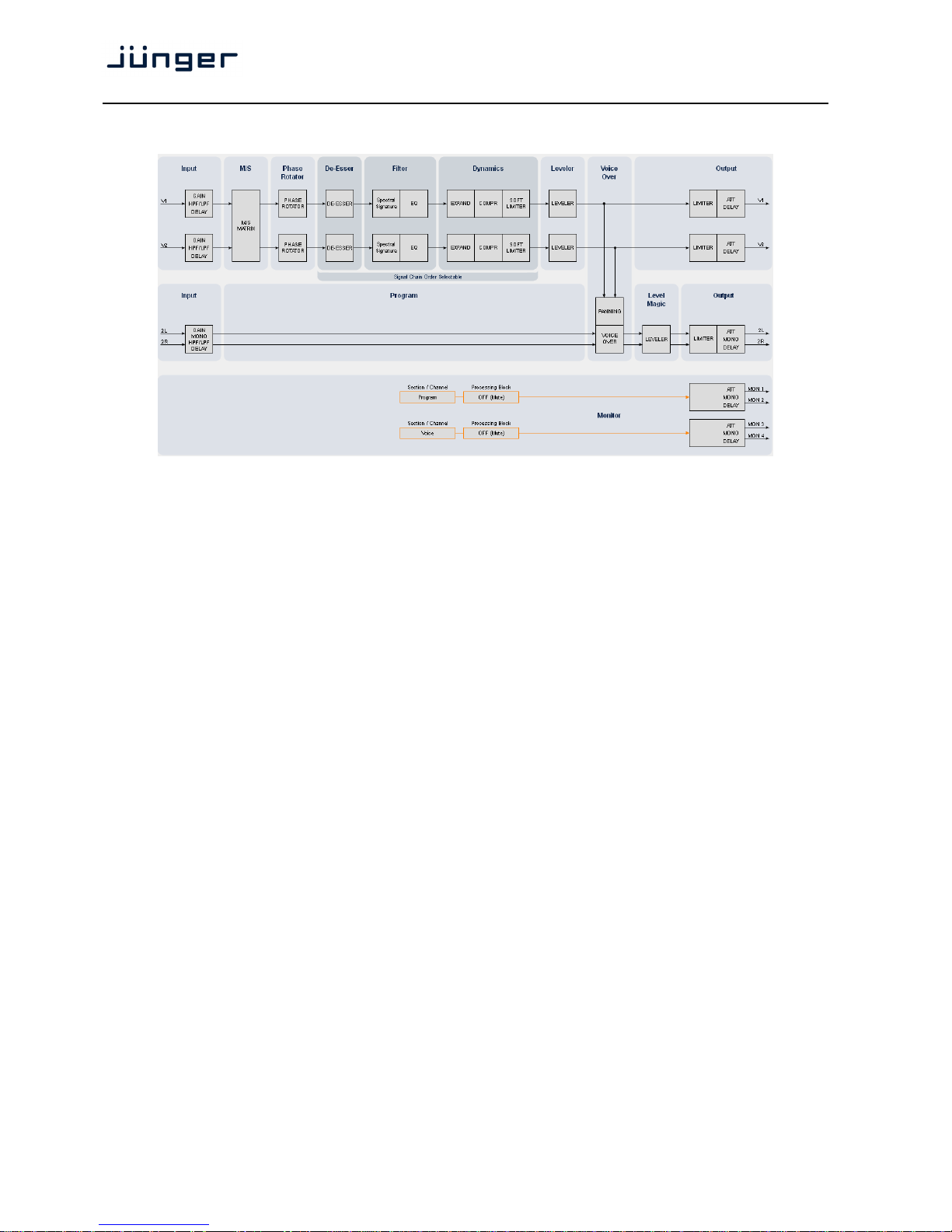
Above you see the various function blocks of the audio processor rendered by the DSP engine.
Each function block has its representation in the GUI by individual tab sheets. You may simply click on the
respective graphical area as an alternative way to navigate through the GUI.
It is important to understand that the physical input interfaces of the device must be routed to the DSP inputs
in order to process it. Similarly the DSP outputs must be routed to output interfaces.
You will find those settings by clicking on the ROUTING tab.
Control Concept
The communication between external applications or the X*AP RM
1
remote panel, is based on
TCP/IP over Ethernet.
The setup GUI utilizes web technology. At the time of editing this manual the functionality of the web GUI is
optimized for Firefox 20.x and higher.
The setup GUI can be complemented by other application programs running on MS Windows® W7/8.1/10
like the Junger Audio Application Manager J*AM. Operator access will also be available for mobile devices
running an appropriate browser on iOS or Android.
An SNMP agent is also available on the device and may be incorporated into a monitoring system.
For 3rd party applications, Junger Audio highly recommends using the Ember+ protocol which is widely
distributed in the European broadcast industry. The user community is also increasing rapidly world wide.
By default, the X*AP RM
1
remote panel and the D*AP4 VAP "talk" Ember natively.
Operating Concept
Further below you will see that the setup GUI for the device is grouped into several parameter areas.
One can reach the parameters via a 3 tier navigation by tabs which may have sub tabs, and the sub tabs may
have pages embedded or extra soft buttons for groups of parameters.
Each function block (parameter area) has dedicated presets. The presets can be recalled at any time during
operation, either by manual intervention via the web technology based GUI, automatically by the internal
event manager or by external applications.
For all relevant settings an ON AIR and a PRESET part exists. I.e. you may either edit the parameters
ON AIR or offline for the respective part of the D*AP4 VAP.
The presets of the D*AP4 VAP are persistent by nature. You are working directly on the preset memory.
I.e. you need not worry about storing such presets, the D*AP4 VAP does it for you.
Page 11

D*AP4 VAP
7
Event Concept
The D*AP4 VAP incorporates a sophisticated event management system.
Events may be combined to perform actions. The D*AP4 VAP offers these event types:
* Preset Events for System set up, Interfaces, Routing, Audio Processing etc.
* Parameter Events to control specific parameters of the VAP
* Measurement Events to control the loudness measurement
* I/O Events for GPOs
* Bypass Events for pre-configured bypass scenarios
These events may be combined with Actions which are fired by Triggers.
Triggers are defined by a logical combination (AND, OR, XOR) of two random trigger sources.
A trigger source may be GPIs, hotkeys of the X*AP RM
1
remote panel, network commands, parameters,
other active events, other active triggers (nested trigger), or device status information (e.g. sync lost).
Getting Started – quick start guide
Before the D*AP4 VAP can be used, there are some basic configuration steps which must be followed in the
order set out below. This example assumes you will process one physical condenser microphone and feed
the signal to your digital mixing desk that runs at 96kHz sampling rate.
* Connect the mic to the XLR CHA input of Interface 2
* Connect the XLR AES/EBU OUT connector to your digital desk
* Connect the BNC SYNC IN to the Word Clock output of your desk
* Hook up the device to your PC network
Consult your IT administrator for assistance if you are not sure about this procedure
- Connect it to a switch or hub or directly to a PC / LapTop by an Ethernet cable
(some PCs need a cross over cable when connected 1:1)
- Find an unused IP address - ask your administrator!
- Assign it that IP address and set the network mask accordingly, a gateway is optional
(see next page for details)
* Open a browser (Latest stable FireFox recommended) and connect with the device
- Type in the IP address as an URL
* Set the sync source
- SYSTEM > Setup > Sync Source Priority > Choice 1=Sync-In WCLK
leave all other Choices x=OFF (for the beginning)
- SYSTEM > Setup > System Clock > Sample Rate (kHz) = Follow Source
* Define the program configuration
- SYSTEM > Setup > Voice Channel Mode=2 x Mono
* Setup the microphone input
- INTERFACES > Analog Mic > M1 > Input=Mic, Enable Preamp Gain=On (check box),
Preamp Gain=40dB, Pad=OFF, Phantom Power=On (check box)
* Set the routing to the Audio Processor (DSP)
- ROUTING > MIC > MIC 1=DSP 1
* Set the routing from the Audio Processor (DSP)
- ROUTING > DSP > DSP 1=AES 1
Now you should have the mic signal on your desk and you may start experimenting with the various
parameters of the audio processing blocks.
Page 12
D*AP4 VAP
8
Getting Started – IP setup in general
The process of installing a D*AP4 VAP into an IP network is as follows:
1. Ask the system administrator for two unique IP addresses of the local area network,
for the netmask used and if a gateway address is necessary.
2. Assign the D*AP4 VAP an IP address
You have 2 choices to assign the D*AP4 VAP an IP address:
* From the serial console interface
* Via Web browser
3. Assign the X*AP RM1 remote panel a unique IP address configuration
4. Attach the D*AP4 unit to the X*AP RM
1
remote panel
Important Note! If you are not familiar with setting up devices for IP communication, we highly recommend
you consult your system service or IT department to assist you.
Getting Started – IP setup
–
via console interface
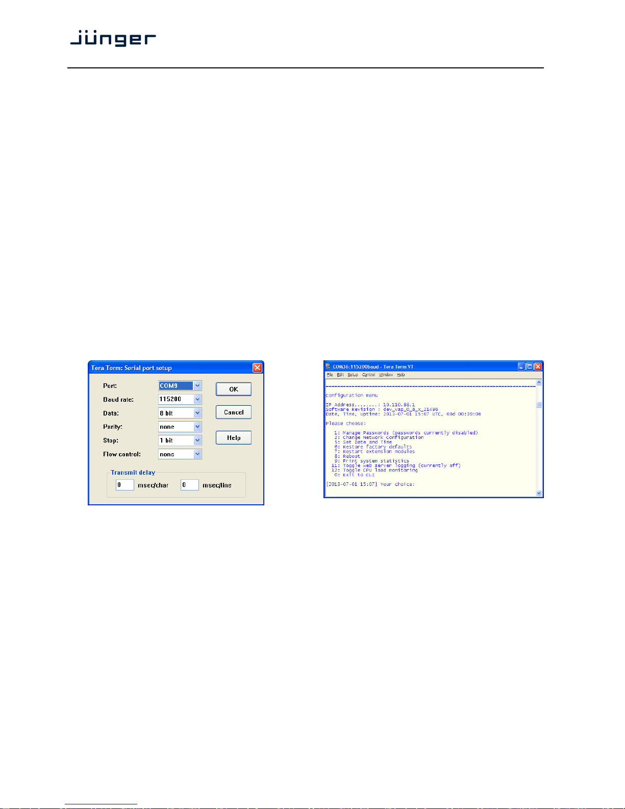
The tool to change the IP configuration of the D*AP4 unit can be reached via the console interface. You must
connect it with the PC via an USB A to B cable. This will install the driver for the built in USB to serial
converter. Now you can open a terminal program. Here you must select the virtual COM port assigned by
the OS. The communication parameters are:
115200kBaud, 8, N, 1 no hand shake. Pressing <ENTER> will open the console menu:
Go for item 2:
"Your choice: 2" <ENTER>
"Current network configuration
IP Address: 10.110.88.1
Netmask ...: 255.255.0.0
Gateway ...: 10.110.0.1
You must enter the IP address and the netmask. Here is an an example:
Enter new IP address, press ENTER to cancel: "192.168.176.78" <Enter>
Enter new netmask, press ENTER to cancel: "255.255.255.0"
<Enter>
Page 13
D*AP4 VAP
9
Important Note! The gateway entry is optional but you must ensure that the gateway address matches the
network mask related to the device IP address!
If you are not sure simply leave it at 0.0.0.0.
Enter new gateway, press ENTER to configure without gateway: <Enter>
Changing Network configuration
The network configuration has been changed. Please reboot the device
to activate the new settings.
Select item 8:
Do you want to reboot the device ? <ENTER>
Press small "y":
Do you want to reboot the device ? y <ENTER>
Rebooting the device ……..
After reboot has finished, the new IP configuration is active and will be displayed at the top of the
configuration menu.
Getting Started – IP setup
–
via web browser
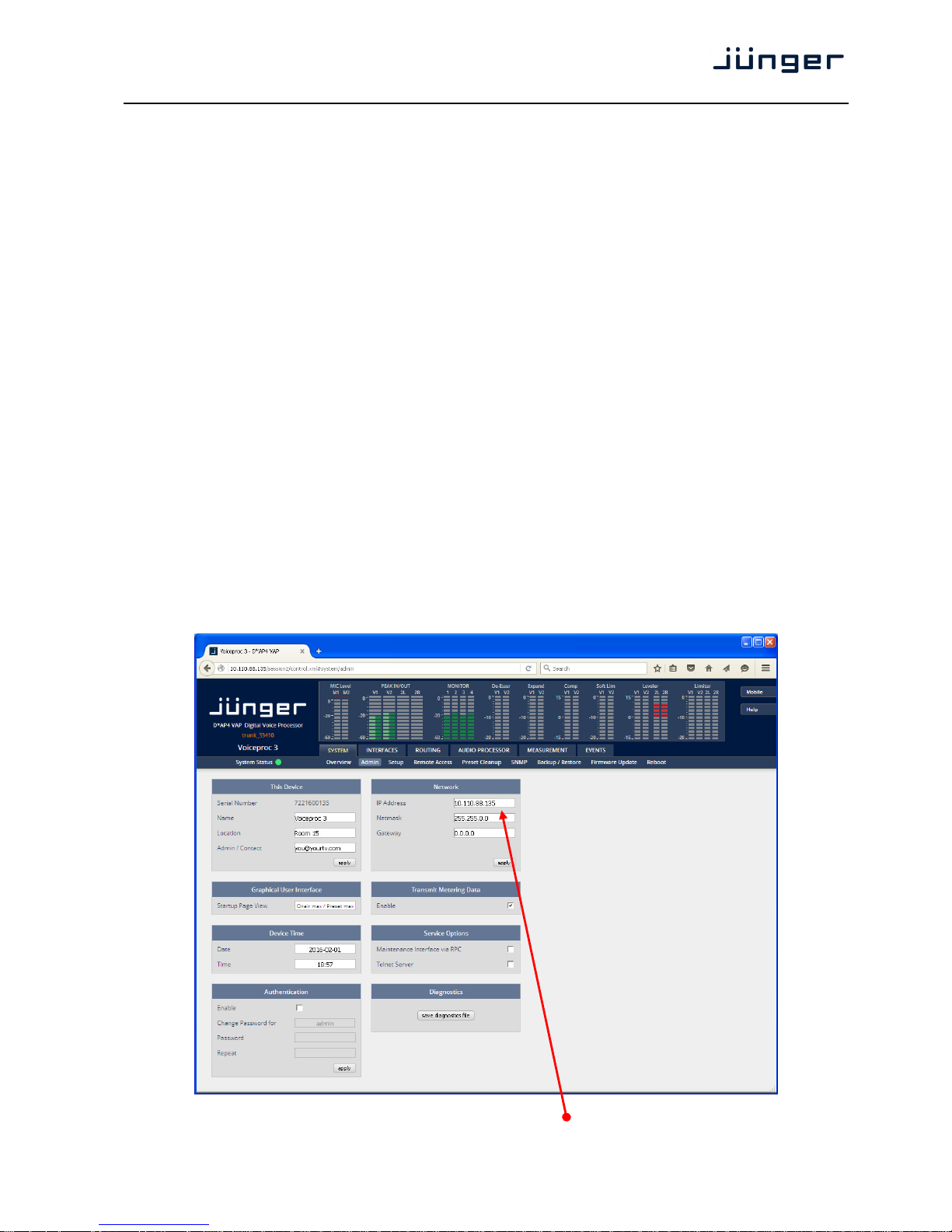
* Read the default IP address printed on the label at the rear of the device.
* Set up network parameters of your PC to fit the default IP address of the D*AP4 unit
(e.g. default IP +1 and net mask = 255.255.0.0).
* Connect the D*AP4 VAP with the PC either by a Ethernet patch or a cross over cable
(if the PC does not support Auto MDI-X) or via a switch.
* Open a browser and type the IP address of the D*AP4 unit into the URL field and press <ENTER>.
This will open the AUDIO PROCESSOR tab sheet of the GUI.
* Click on <SYSTEM> and afterwards the "Admin" tab:
Enter the desired network configuration and press <apply>
Page 14
D*AP4 VAP
10
Afterwards you must reboot the D*AP4 unit in order to activate the new IP configuration.
Important Note! After reboot neither the web browser nor the X*AP RM
1
remote panel may be able to
communicate with the D*AP4 device. You must fill in the new IP address in the URL field and change
the X*AP RM
1
remote panel settings to attach this device with its new IP address.
Operating - menu structure of the X*AP RM
1
remote panel – power up display
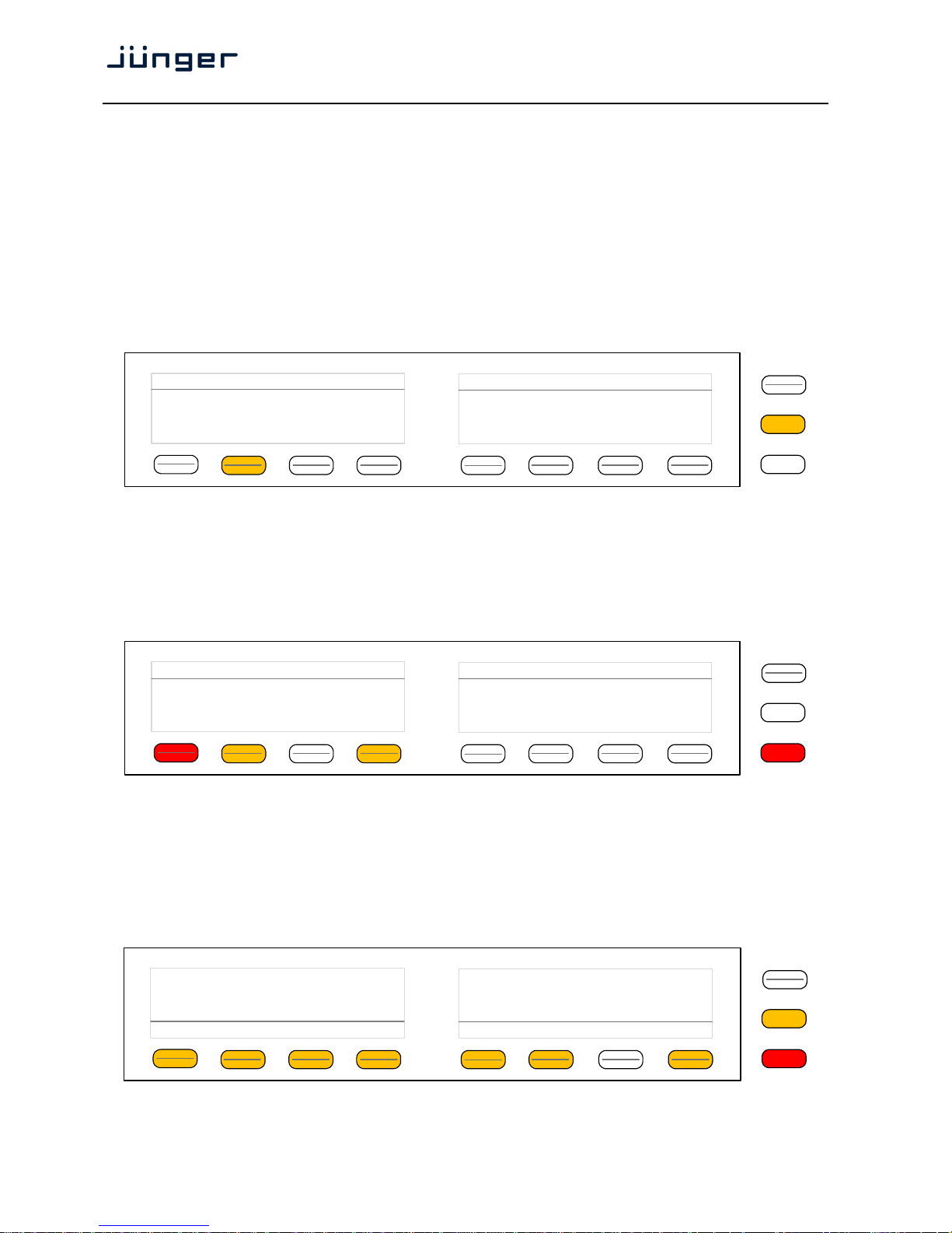
Power up display – may show up to four D*APx which are enabled for remote control via this X*AP RM
1
remote panel. The example below has just one D*AP4 VAP unit [given name "Voiceproc 3"] attached for
remote control. The status is "connect" (i.e. you may connect with that device).
See X*AP RM1 manual for details.
Pressing that button will connect with the D*AP4 VAP.
Now the X*AP RM
1
remote panel will gather all necessary information from that D*AP4 VAP unit
(this may take a few seconds). When finished the main operating display opens up.
The appearance of that display depends on the setting found in:
SYSTEM > Remote Access > X*AP Remote > X*AP Remote Feature Set. If it is set to
"Load Profiles [Voice x]" the capabilities are limited to load such profiles, to control the cough cut and to
activate the voice over function manually (AUDIO PROCESSOR > Voice Over > Mode = "Manual"):
From here you may fire pre-defined hotkeys and observe the status of both voice channels.
"Voice 1" is the default name of the first voice channel.
If SYSTEM > Setup > Voice Channel Mode = Stereo, settings will be made in reference to the first voice
channel. Because this is the main operating display, the <ESC> button lights
red to indicate that the
power up display is below the main operating display.
Pressing
<ESC> sends you back to the power up display (device selection).
If the X*AP Remote Feature Set "Standard Set" is selected, this main operating display will be shown
(example for Voice Channel Mode = Stereo):
Now you may fire the pre-set actions (see EVENTS > Actions > Event Actions) via the hotkeys.
You may configure these buttons via: EVENTS > Triggers > Remote Hotkeys and > Trigger Equations.
MENU
ESC
Remote Panel select device to control
Voiceproc 3
10.110.1.55 [Voice1]
connect
MENU
ESC
Voiceproc 3
10.110.88.135
Cough Cut
Mic Active
ON AIR
Load Profile
_
Voice 1
Voice Over
OFF
MENU
ESC
Voice 1
Voiceproc 3
10.110.88.135
.
Clear Just De-Ess Gentle Radio Normalize Heavy Panic
-
ON AIR
Mic Active
Page 15
D*AP4 VAP
11
Operating – menu structure of the X*AP RM
1
remote panel – operating displays
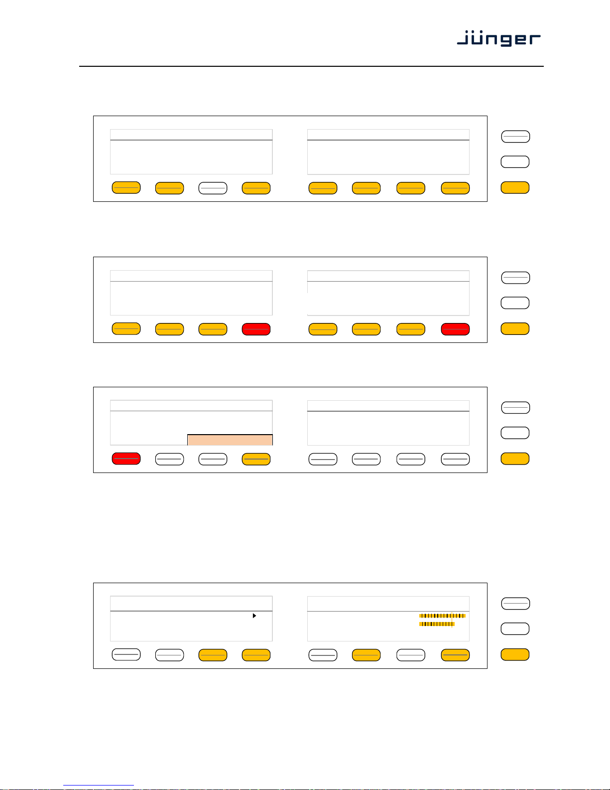
When pressing the <MENU> button, the upper operating display opens up:
When pressing the <ESC> button you will return to the main operating display.
Operating display – Analog Mic Interface
Here you can setup both mic preamps.
Operating display – ON AIR profiles
This is the same menu that you will reach if the feature set "Load Profiles" is selected
(see previous page). Here you may remote control the cough cut for the respective voice channel and
load a pre-defined profile. A profile is a set of audio relevant presets that must be set-up in the:
EVENTS > Events > Preset Events section. Pressing the <Load Profile> hotkey will highlight the area
above the button (see above – the default display is a dash). You can now select a profile by turning the
Rotary Encoder. After the selection you must press the Rotary Encoder or the <Load Profiles> hotkey.
Operating display – Loudness Meter
The meter style (ITU BS.1770-x / ATSC / EBU etc.) is defined by the settings of:
AUDIO PROCESOR > Level Magic > Loudness Mode (example is for EBU R12().
The above menu serves as a display of measurement values and offers the metering control buttons
(reset & pause / continue).
MENU
ESC
EBU R128 Integrated LRA Time
[LUFS] [LU] hh:mm:ss
Input -19.3 6.4
Output -23.2 5.8 00:12:15
Short-Term TPL Max Momentary
[dBTP] Max
-19.7 -6.6 -12.0
-21.3 -5.0 -16.0
reset max
pause
reset
MENU
ESC
Voiceproc 3 10.110.88.135
Gain EnableonGain [dB]10Pad [dB]
OFF
Gain Enable
off
Gain [dB]
10
Pad [dB]
OFF
M1 Preamp M2 Preamp
Phantom
Power
off
Phantom
Power
off
MENU
ESC
Voiceproc 3
10.110.88.135
Analog Mic
Interface
ON AIR
Profiles
ITU BS 1770-3
Meter
Audio Processor Monitor Monitor
Voice Program 1/2 3/4
MENU
ESC
Voiceproc 3
10.110.88.135
Cough Cut
Mic Active
Voice 1 ON AIR
Load Profile
Radio Voice
Voice Over
OFF
Page 16
D*AP4 VAP
12
Operating display – Audio Processor > Voice
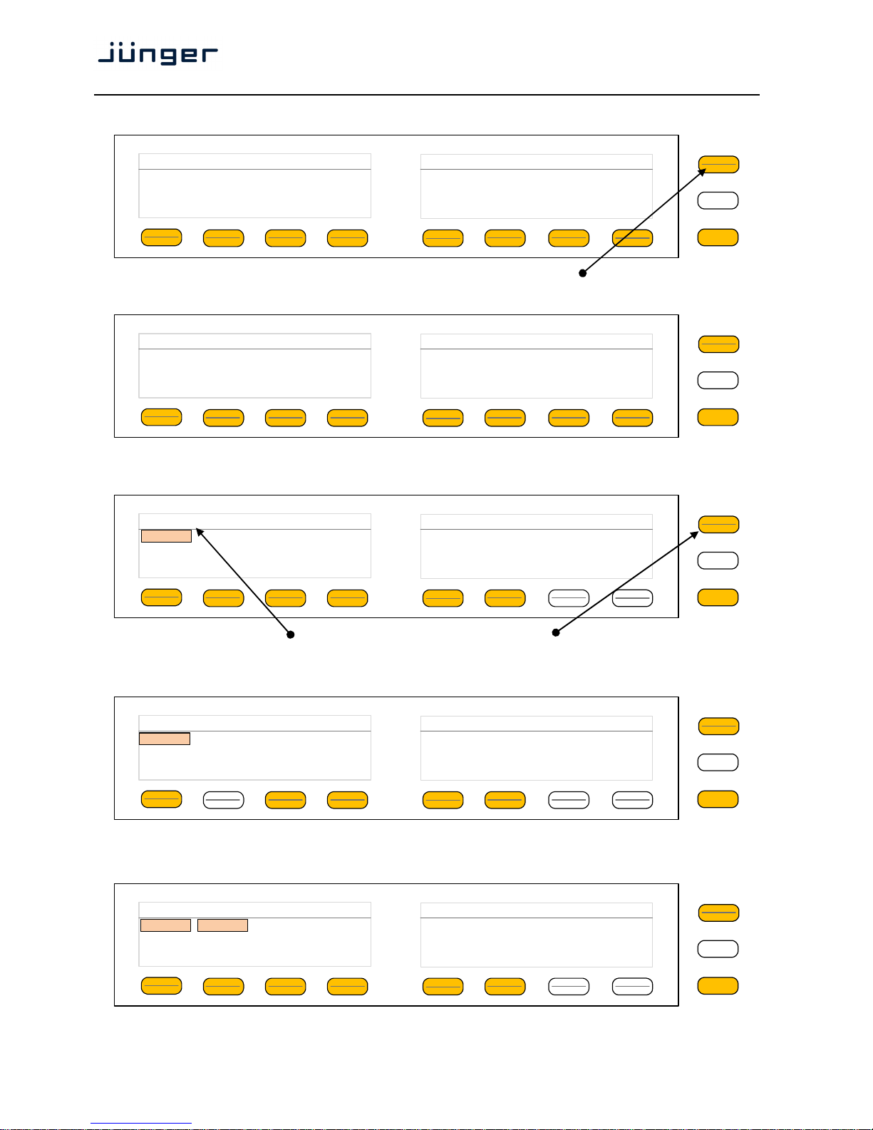
This menu gives access to tweak the voice channel(s). The active <Shift> button indicates that there
is another page (2/2):
The example below explains how to set parameters via the X*AP. E.g. if you press <Input>
all parameters for the Input function block will be accessible (here we assume Stereo mode):
Here you are at the input section of the voice channel. The <Shift> button
again toggles between two pages and gains access to the remaining parameters.
Here is the example for page 2/2 after pressing the <Shift> button:
If the voice channels operate in stereo mode: SYSTEM > Setup > Voice Channel Mode = Stereo,
you are able to link / unlink the respective processing blocks (see AUDIO PROCESSOR > Input):
The above example shows both voice channels in Linked mode.
MENU
ESC
Audio Processor Voiceproc 3 10.110.88.135 1/2
Input
M/S
Matrix
Phase
Rotator
Equalizer
Voice
Spectral
Signature
Dynamics LevelerDe-Esser
MENU
ESC
Audio Processor Voiceproc 3 10.110.88.135 2/2
Voice
Ouput
MENU
ESC
Voice: Input Link On Mute Gain[dB] Polarity 1/2
V2 Linked On off 0.0 Normal
1/2
MENU
ESC
Voice: Input Delay Coarse [ms] Fine [samples] HPF [Hz] LPF [kHz] 2/2
1/2 0 0 OFF OFF
1/2
MENU
ESC
Voice: Input Link On Mute Gain[dB] Polarity 1/2
V2 Unlinked On off 0.0 Normal
1/2
Linked
Page 17
D*AP4 VAP
13
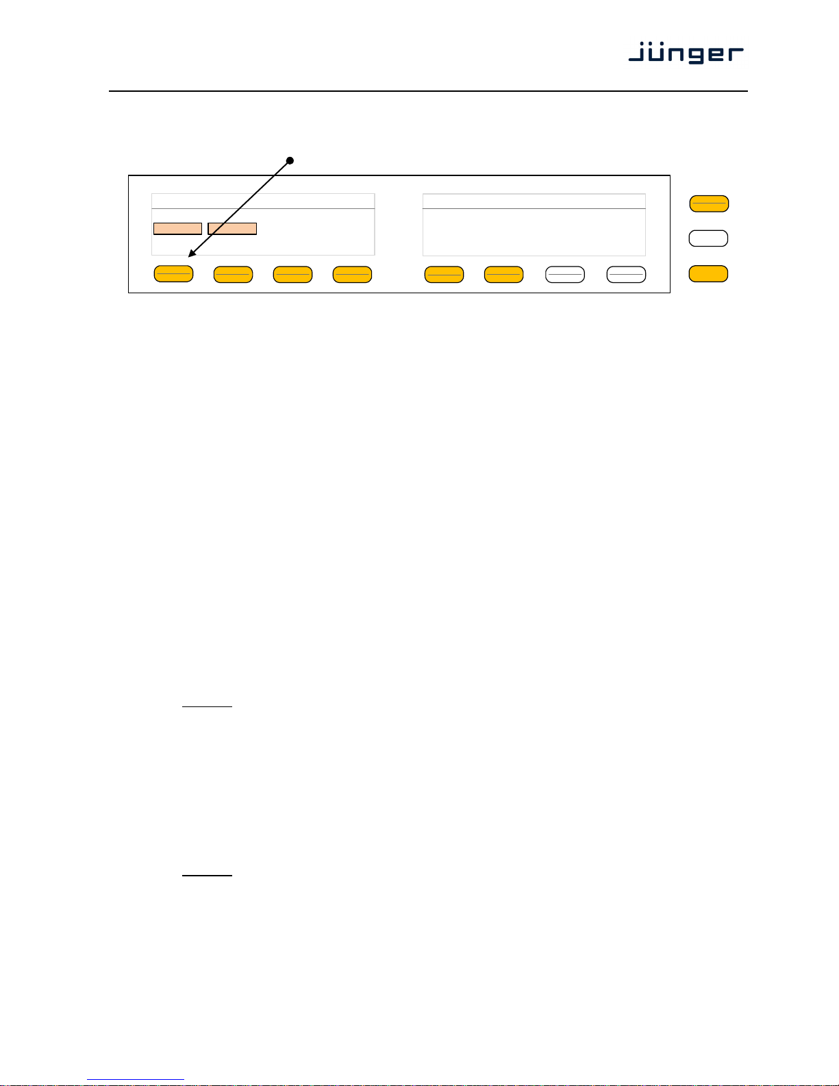
When you press hotkey #2 you are able to unlink both channels. Now you must simply push the rotary
encoder (or turn it counter clockwise / clockwise) to toggle between Linked and Unlinked condition.
In case of Unlinked, the display shows two independent parameter sets.
By pressing hotkey # 1 you can toggle the voice channel that is under control:
The examples above demonstrates the general way how to setup parameters of the
AUDIO PROCESSOR of the D*AP4 VAP:
* Select a parameter
* Change it by using of the Rotary Encoder.
- Push it to toggle states
- Turn it to increment / decrement values.
Important Note! Not all processing blocks can be linked / unlinked. Carefully compare the settings via the
web GUI if you are not certain about individual settings. In general the X*AP RM
1
menus are a duplication of
the GUI settings. To access all parameters of a function block you must sometimes use the <Shift> button.
E.g. the equalizer has 5 pages for one voice channel!
Operating – menu structure of the X*AP RM
1
remote panel – menu tree
Power up display
<MENU> opens X*AP RM1 remote panel IP setup menu. See X*AP RM1 manual for details.
<Address> setup
<Netmask> setup
<Gateway> setup
<empty>
Device 1 setup IP & ON / OFF
Device 2 setup IP & ON / OFF
Device 3 setup IP & ON / OFF
Device 4 setup IP & ON / OFF
<ESC> back to power up display
<connect> will connect with that particular D*AP4 VAP and opens the main operating display:
Hotkey #
1 <Clear>
2 <Just De-Ess>
3 <Gentle>
4 <Radio>
5 <Normalize>
6 <Heavy>
7 <empty>
8 <Panic>
<ESC> will jump back to power up display
<MENU> opens the upper operating displays:
Hotkey #
1 <Analog Mic Interface>
2 <ON AIR Profiles>
3 <not active>
4 <Loudness Meters>
5 <Voice>
6 <Program>
7 <Monitor 1/2>
8 <Monitor 3/4>
<ESC> back to main operating display
MENU
ESC
Voice: Input Link On Mute Gain[dB] Polarity 1/2
1 Unlinked On off 0.0 Normal
V2 Unlinked On off
0.0 Normal
2 Unlinked
Page 18
D*AP4 VAP
14
Setup GUI – connecting with the D*AP4 unit – AUDIO PROCESSOR > Overview
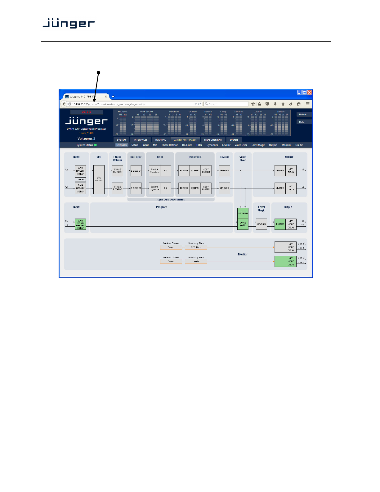
You must open a browser and enter the IP address of the D*AP4 unit
into the URL field and press <Enter>. The browser will fetch the necessary information and will open the
entrance page:
The entrance page is the AUDIO PROCESSOR pane with its sub pane Overview. If you are returning from
other pages or if you reload your browser content (by pressing <F5>) it may show a different page due to
caching of the browser.
In the top section you see several bar graph displays for signal levels as well as for gain reduction display of
several function blocks.
On the following pages we will go through the various panes to perform the basic setup of the device.
You must set up the synchronization source. You may also give the device a name, tell it its location and
define an administrative contact which may be used by the monitoring system of your house (e.g. via SNMP).
You must set up the installed interface module and finally set the signal routing.
You will find those settings under the SYSTEM link.
Page 19
D*AP4 VAP
15
Setup GUI – SYSTEM – System Status
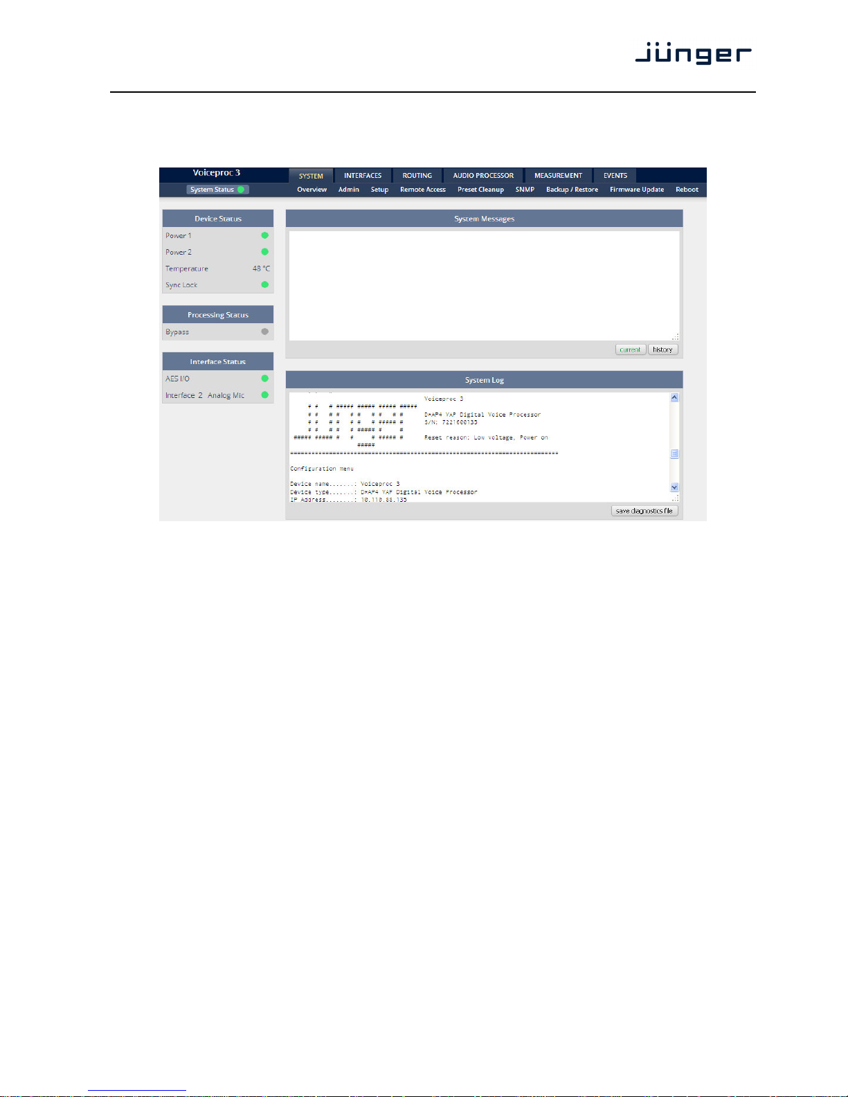
The system status is a special link you can reach independently from where you are:
The System Status page provides a top level view of the various status information available for the device.
Device Status Provides the hardware status of the D*AP4 VAP.
Power 1 Status of the first power supply (left hand side of rear).
Power 2 Status of second power supply (to the right of the first power supply)
Temperature Measured on the surface of the main PCB.
Sync Lock Turns red if the external sync source is lost or unstable.
Processing Status
Bypass Turns red if Bypass is activated.
Interface Status
AES I/O Turns red if an AES input that is internally in use (i.e. you have routed it to
an input of a function block) has detected an error (e.g. no carrier).
Interface 2 Analog Mic Turns red if a problem with the optional mic interface board has been
detected.
System Messages [current / history]
Displays a list of messages produced by the system controller.
System Log The system controller messages will be logged. This log information may
be downloaded from the device and sent to Junger Audio. In case of a
problem you can press: <save diagnostics file> from here or from:
SYSTEM > Admin > Diagnostics.
Page 20
D*AP4 VAP
16
Setup GUI – SYSTEM – Overview
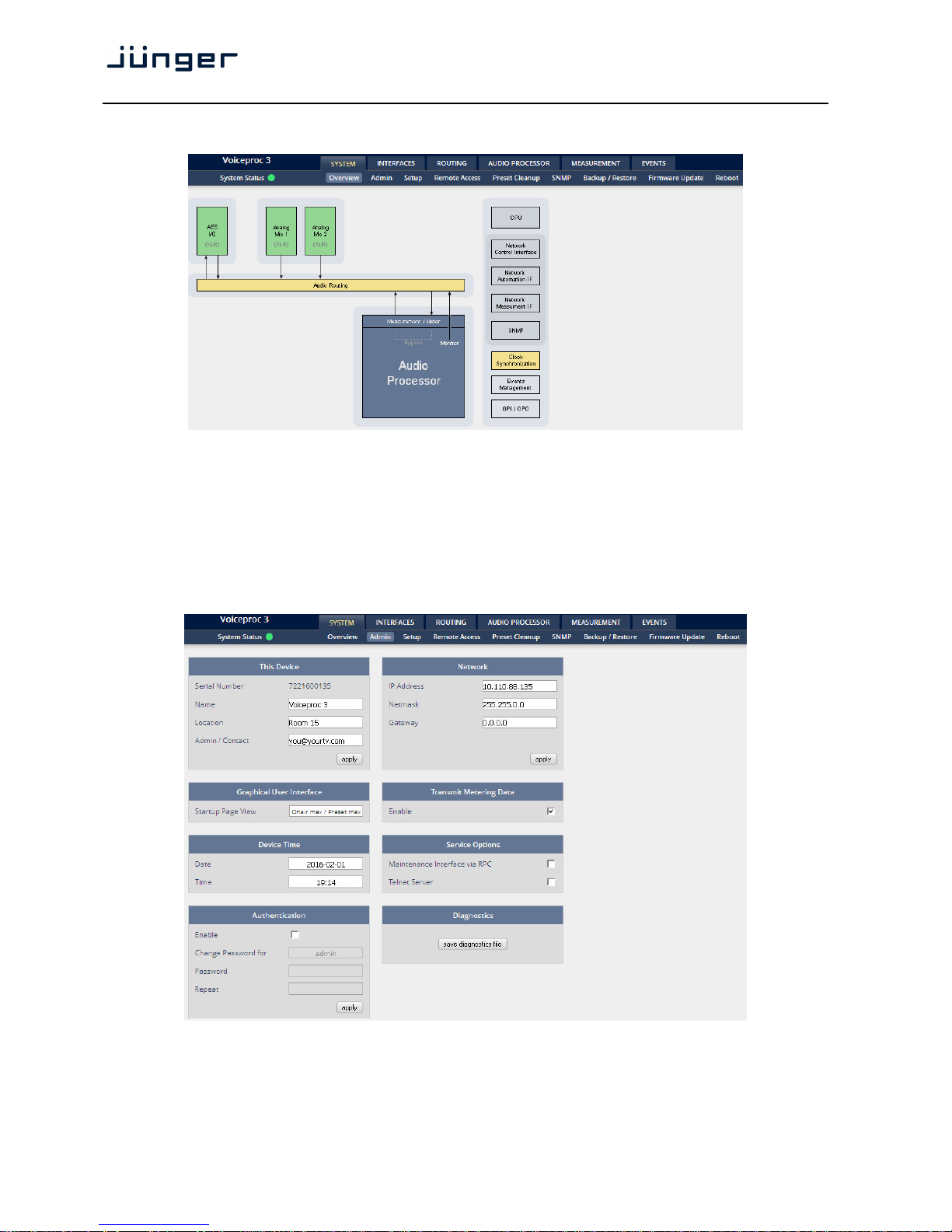
The graphical overview shows the main building blocks of the device including the options installed,
in this example the microphone interface is placed into the INTERFACE 2 (see rear view)
and a MADI I/O module is placed into INTERFACE 1 slot.
You may click on the boxes and the respective setup page will open. The navigation is based on URLs so
you may use the <Back> navigation button of the browser to return to this page.
Setup GUI – SYSTEM – Admin
Page 21
D*AP4 VAP
17
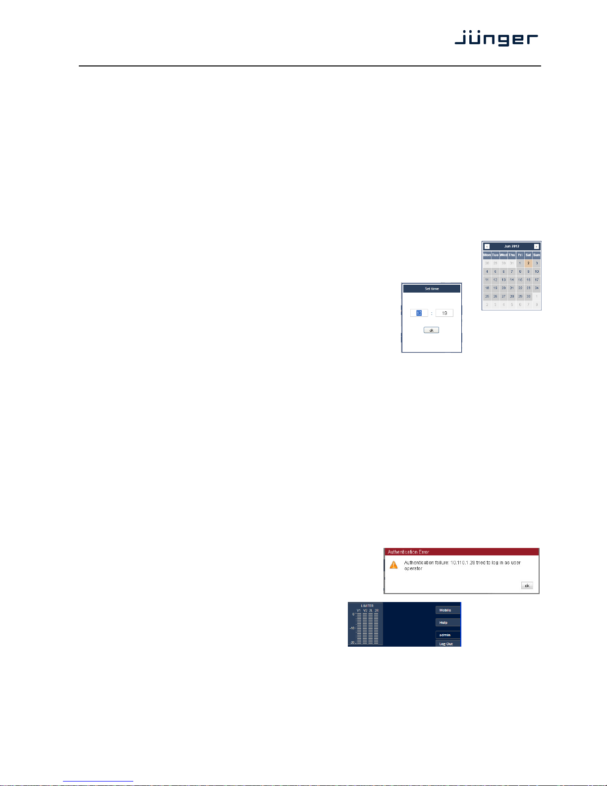
This Device Input fields for information utilized by higher level services.
Serial Number The electronic serial number. It is printed on a label at the rear of the
device.
Name Give the device a meaningful name that may be used by name services
and SNMP management.
Location The place where the D*AP4 VAP is located.
Admin / Contact e-mail address of a person in charge.
Graphical User Interface Defines the appearance of the parameter panes regarding preset editor
and on air parameter visibility (see below – for preset concept).
Startup Page View Defines the appearance of the parameter panes regarding preset editor
and on-air parameter visibility (see below – for preset concept).
Device Time Allows you to set the device clock. At the factory it is set to
UTC (Coordinated Universal Time).
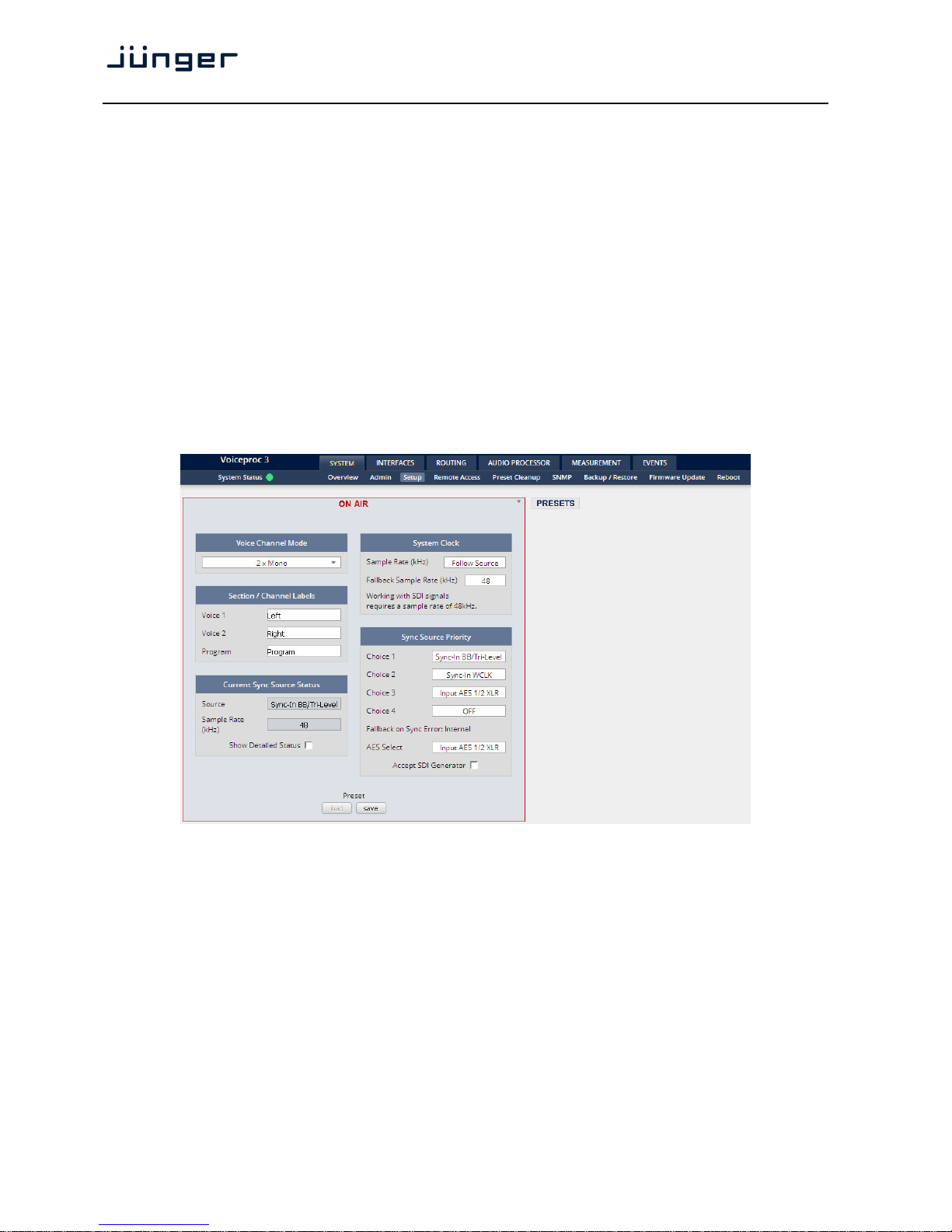
Date If you click into the Date input field, you'll get a calendar tool:
Time If you click into the Time input field,
you will be able to set the device time:
Authentication To prevent non-authorized people from
changing D*AP4 VAP settings the
administrator may assign passwords for
either the admin and/or an operator
(same applies for talent/artist). While the admin is allowed to set everything,
an operator is just allowed to load presets. Parameters will be reset if the
operator attempted to change it.
Enable [enable / disable]
The administrator may turn authentication off.
Change Password for [ON / OFF]
Select which password you will set / change.
Password Type in a password
Default passwords are: admin (for admin) and operator (for operator).
Repeat repeat that password
Important Note! The authentication may be enabled / disabled form the console interface as well
(see page 8 "1: Manage Password") via USB connection but also via Telnet! If you have higher security
demands you should turn the Telnet server off. Authentication will be turned off and passwords will be reset if
one initializes the device to factory default (see Reboot - page 19, INIT/RESET rear button - page 4).
If there was an authentication failure, the admin will be notified at
the next proper login about such conditions. The pop up appears
for each login that has failed. It shows the IP address of the device
that caused the Authentication failure.
After a correct login the status "who" (e.g. admin)
and a <Log Out> button are available from the GUI:
Network IP address setup, see above:
getting started – IP setup of the D*AP4 VAP
–
via web browser
IP Address The address of your choice – default [10.110.xxx.yyy]
Netmask The net mask of your network – default [255.255.0.0]
Gateway The optional gateway address – default [0.0.0.0]
Page 22
D*AP4 VAP
18
Transmit Metering Data [OFF / ON]
Metering data will be streamed via UDP protocol. In order to receive such
data by external applications you must enable it.
Service Options
Maintenance Interface [OFF / ON]]
via RPC For administrative use to enable communication with factory tools.
Telnet Server [ON / OFF]
Enables a telnet server to connect the consol interface via IP (port 21).
Diagnostics
<get diagnostics file> Pressing this soft button will start the assembly of a diagnostics file.
The file will be presented in XML format for download.
If you experience unexpected behavior of the device you may be asked by
the Junger support team to send such file by e-mail for analysis.
Setup GUI – SYSTEM – Setup
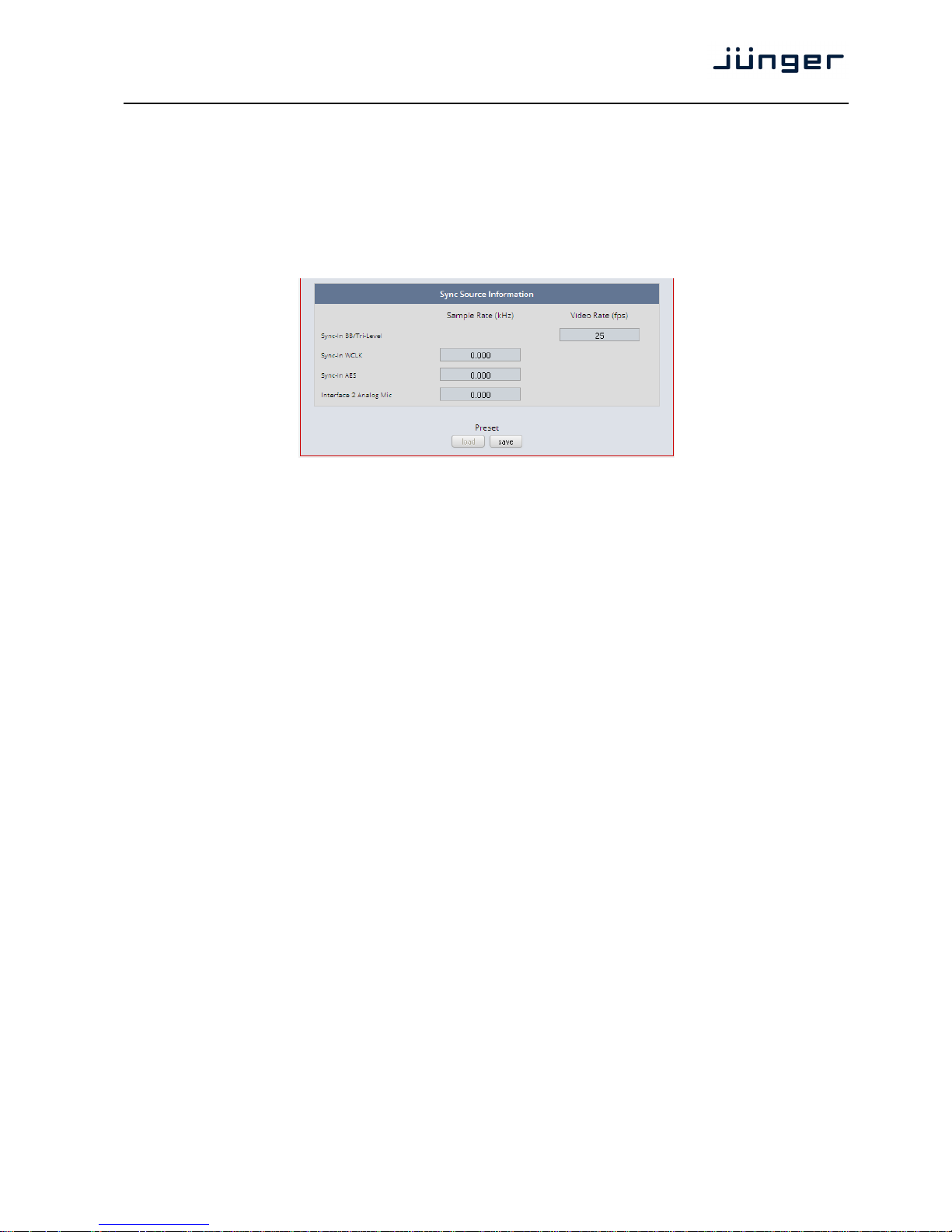
Voice Channel Mode [2 x Mono / Stereo]
Set according to the type of voice signal. This will automatically
configure all relevant audio processing blocks.
Important Note! If set to "Stereo" all relevant settings will provide an unlink function in case you need to
setup both channels differently for any reason. I.e. the layout of several panes and the X*AP RM
1
will differ
depending on this setting. If put into "Stereo" mode the label for Voice 1 (see below) will be used.
Section / Channel Labels Each of the individual voice channels as well as the program path
Voice 1 has a name that will be used as a reference for the display of
Voice 2 parameters and their setup. You may use names of your choice.
Program Default names are Voice 1 / Voice 2 and Program.
Page 23
D*AP4 VAP
19
Current Sync Source Status shows the status of the 5 tier sync priority circuit
Source active sync source
Sample Rate measured sample rate
Show Detailed Status [ON / OFF]
If you enable the checkbox you will get this additional information:
Sync Source Information
System Clock
Sample Rate (kHz) [Follow Source / 44.1 / 48 / 88.2 / 96]
Fallback Sample Rate (kHz) [44.1 / 48 / 88.2 / 96]
Sync Source Priority
Choice 1 – 4 [OFF / Internal / Sync-In WCLK / Sync-In AES
{or Input AES 1/2 XLR or Input AES 1/2 BNC} / Interface 1 {SDI I/O
or AES I/O or non} / Sync-In Black Burst/Tri-Level]
Fallback on Sync Error: Internal
If the selected sync source is not available the next source will be
selected. If none of the pre selected sync source is not available,
the source will fall back to the internal clock oscillator.
AES Select [OFF / Sync-In AES / Input AES 1/2 XLR]
Accept SDI Generator [ON / OFF]
For rare application you may use the SDI generator (if an SDI I/O
interface is installed) as the sync source. In this case downstream
equipment must be synchronized to the D*AP4 VAP.
See INTERFACES > SDI I/O interface > Setup for details.
Important note! It is not possible to gen-lock the SDI generator. The generator will run on its own
internal 27MHz crystal clock.
Setup GUI – SYSTEM – Remote Access – X*AP Remote
The VAP is designed for multi user applications where users will frequently alternate.
Since the VAP has two fully loaded processing channels one may use it for two independent mics from
different sound booths. On the other hand the X*AP can control multiple VAPs one by one and a single VAP
may be controlled from multiple X*APs. This requires a flexible remote concept that allows you to recall preset configurations from the X*AP panel or from the mobile UI. You can control pre-settings of the EVENTS
system via remote access from the X*AP remote panel or from a mobile UI on a tablet, a smart phone or
even via a browser session from any PC in the network.
To better understand the possibilities of these settings it is recommended to study the comprehensive
EVENTS system of the D*AP4 VAP.
Page 24
D*AP4 VAP
20
At the moment of connecting a particular X*AP with a VAP the VAP configuration will be transferred to that
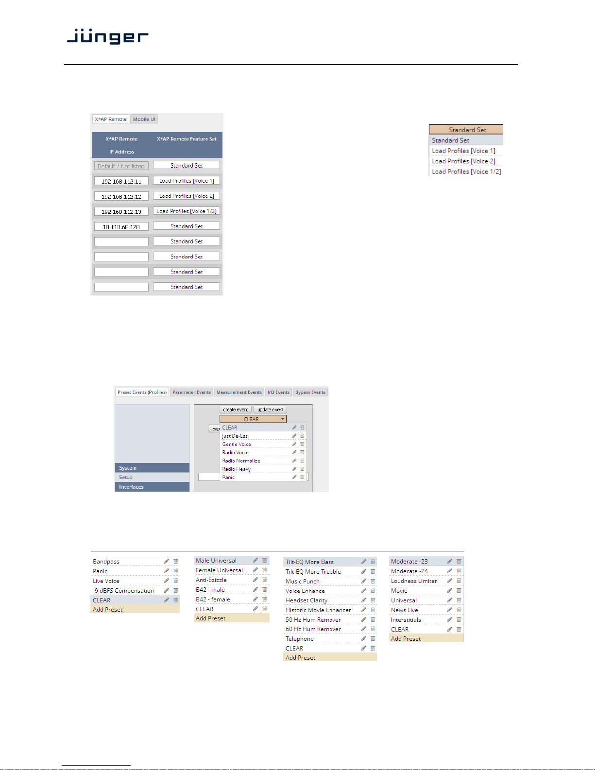
X*AP. I.e. configuration must take place at the VAP. Which feature set a particular X*AP is allowed to control
you must decide here:
Multiple X*AP remote panels may gain access to the VAP.
For each X*AP you may pre-set Feature Sets:
Profiles will be set up in the EVENTS > Events > Preset Events
(Profiles) area. They combine a number of presets of several
processing blocks.
IP Address In the first line you define the access
policy for an "unknown" X*AP that
connects with this VAP for the first time.
The other lines are used to pre-define
features for known X*APs. When
enabling an unknown X*AP to connect
with this VAP, the respective IP address
will be inserted automatically into the next
empty line.
When you restore the factory defaults after an update to the latest VAP firmware via
SYSTEM > Reboot > Restore Factory Default Settings, you will find a number of
factory configured preset events also called profiles:
These profiles are based on factory default
presets of various function blocks.
The VAP offers a variety of such
pre-configured presets in all relevant
function blocks to ease the use of the VAP
in most day-to-day applications.
Here are a few examples of factory default presets of the AUDIO PROCESSOR:
> Input: > De-Esser: > Filter > Equalizer: > Level Magic:
Page 25
D*AP4 VAP
21
Setup GUI – SYSTEM – Remote Access – Mobile UI
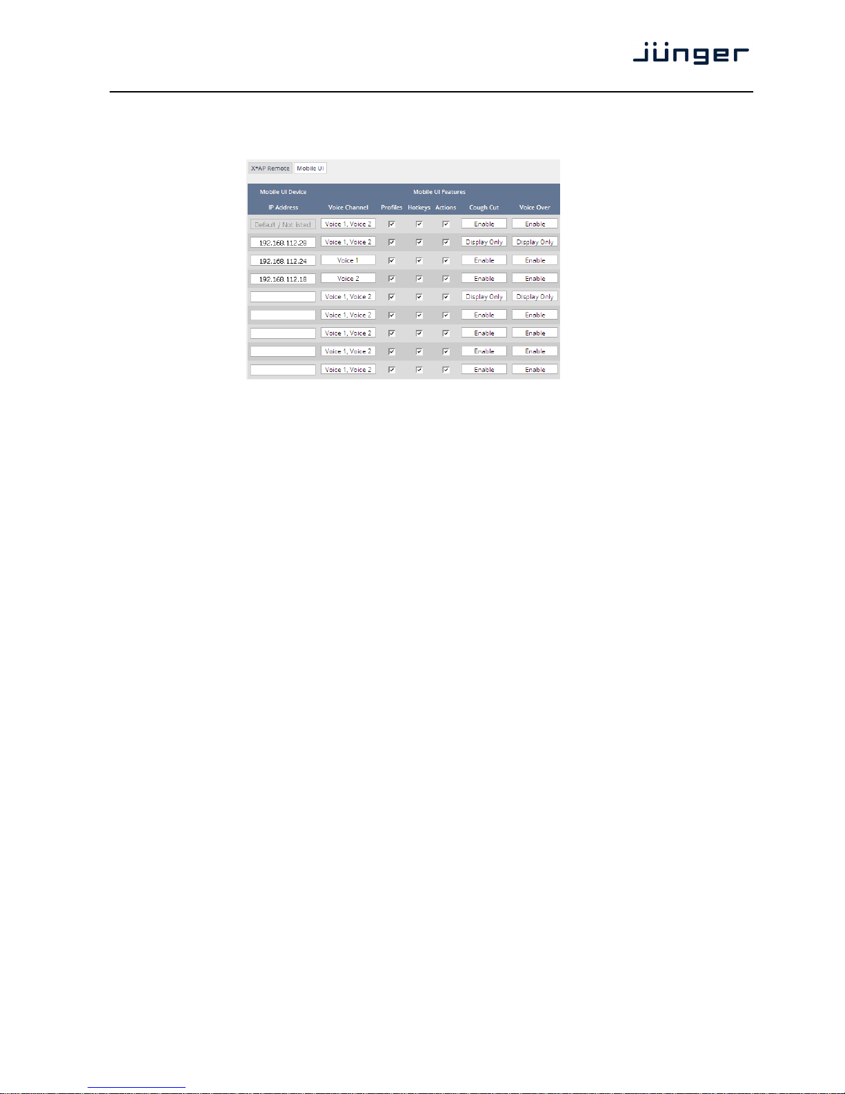
For operator UIs on tablets, smart phones or PCs you can assign the features via its IP address:
IP Address When connecting from a mobile device that is not pre-set, the
respective IP address will be automatically inserted.
Voice Channel [Voice1 / Voice 2 / Voice1, Voice2]
Profiles [ON / OFF]
Turn it on if the respective UI should show profiles to load.
Hotkeys [ON / OFF]
Turn it on if the UI should display the hotkeys of the X*AP that is
connected with this VAP.
Actions [ON / OFF]
Turn it on if the UI should show actions to trigger from the UI.
Cough Cut [Enable / Display Only / Hide] the <Cough Cut> button of the UI.
Voice Over [Enable / Display Only / Hide] the <Voice Over> button on the UI.
It will appear in the UI if manual voice over is selected
(see AUDIO PROCESSOR > Voice Over > Mode = Manual).
Page 26
D*AP4 VAP
22
Setup GUI – SYSTEM - the preset concept in detail
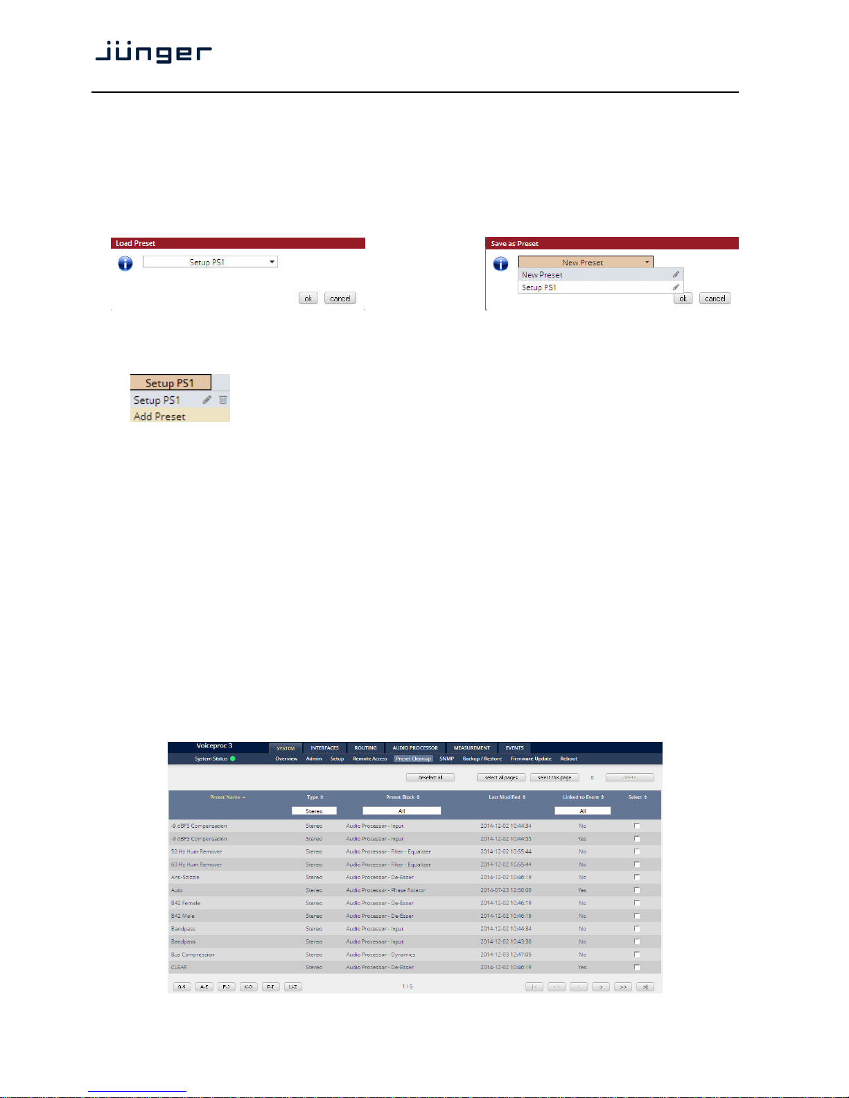
The example above shows the preset concept of the D*AP4 VAP. It is a general feature of the device
and you will come across it in almost every area. For all relevant settings one set of ON AIR parameters
and a practically unlimited number of PRESETS are available. The count depends on the NV memory
space left. If you want to load parameters from a preset to the ON AIR area or save parameters from the
ON AIR area to a preset, you must press:
<load> or <save>:
A dialog opens to select the desired preset. When you press <ok> the selected action will be executed.
When you press the little pencil icon the preset name turns italic and you may edit it.
To generate a new preset offline, you must click into the preset name field below the PRESET headline:
The pull-down offers "Add Preset". If you select this a new entry to the list will be
generated. Clicking on the small trash bin symbol will delete that preset.
You may change the default name "Preset x" by clicking the small pencil icon.
Now the default name becomes italic and you may edit that name.
If you have selected the new preset or one of the existing presets indicated by the name displayed at the
top, you may edit the parameter values.
Important Note! The presets of the D*AP4 VAP are persistent by nature. You are working directly on the
preset memory, i.e. you need not worry about storing such presets. The D*AP4 VAP does it for you.
On the other hand you must be aware that you are overwriting the actual preset settings! If you want to
keep original values (e.g. from a factory preset) you must simply copy the content of the existing one to the
clip board, add a new preset, name it differently and paste the clip board to it.
At the bottom of the PRESET part you will find the soft buttons to <copy> the content of that preset to the
clip board or to <paste> the content of the clip board into another preset which you have selected before
pasting.
You may also <export> or <import> the preset content to / from a file.
Setup GUI – SYSTEM – Preset Cleanup
It is sometimes desirable to delete presets which are used by multiple events without stepping through all
processing blocks and deleting the respective presets one by one. This pane offers you a tool to remove
presets via a central access point:
Page 27
D*AP4 VAP
23
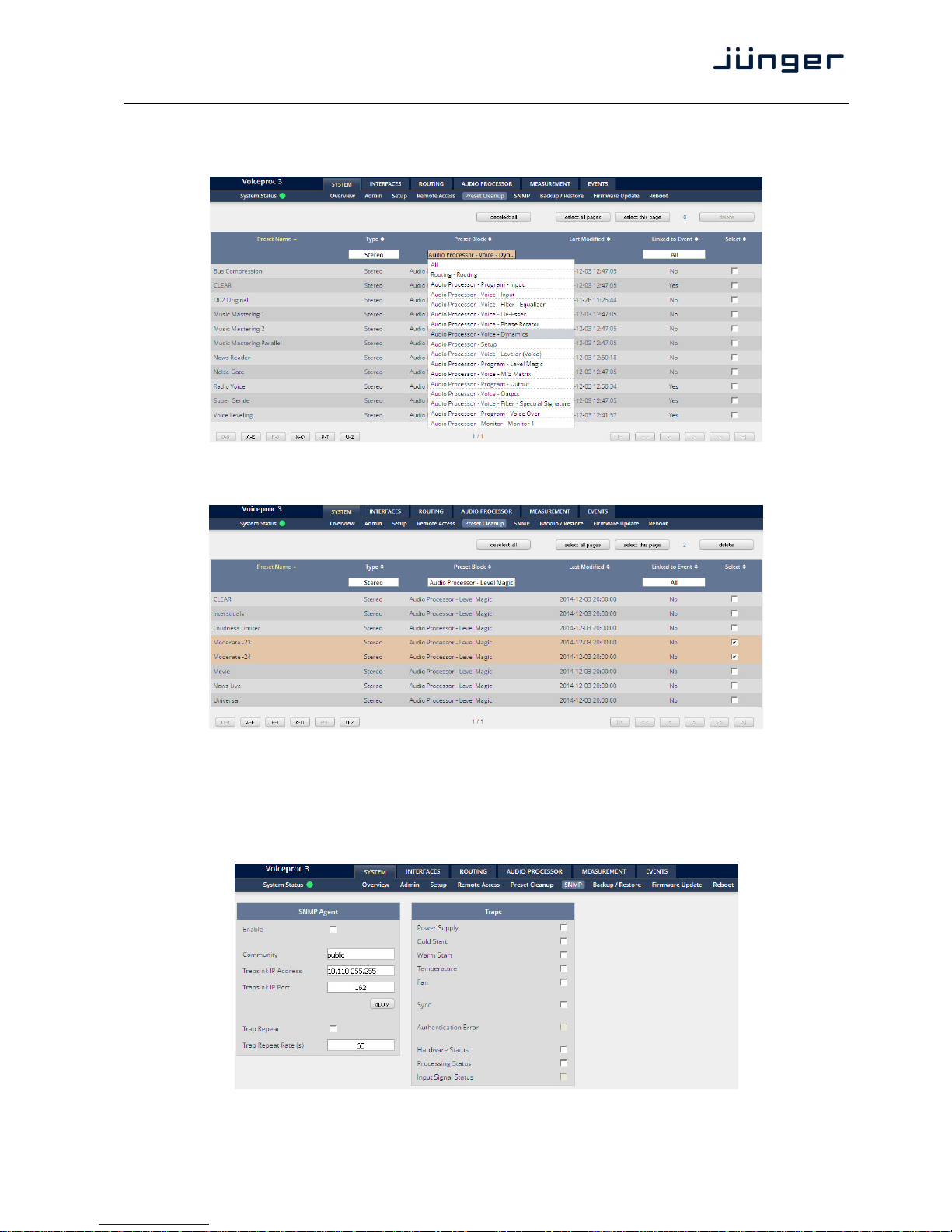
You can sort the table by pressing on one of the column headlines. You can qualify your selection by the
"Type" selector and / or the "Preset Block", "Linked to Event", "Last Modified" column headlines.
The pull down lists allow to reduce the number of presets displayed:
The soft buttons at the bottom left hand side may also be used to search through the table by sorting it by the
first letter or leading number. The arrow buttons at the bottom right hand side can be used to scroll through
the table if the selection is too big for one page:
A selection is made by clicking on a line to activate the check box. Once you have made your selection
(highlighted lines) you can press the <delete> soft button to execute the process. This will remove the
selected presets permanently from the device.
Setup GUI – SYSTEM – SNMP
This pane is meant for basic settings of the SNMP Agent of the device. If you don't use SNMP based
system monitoring, you should not enable the SNMP agent.
Page 28
D*AP4 VAP
24
Setup GUI – SYSTEM – Backup / Restore
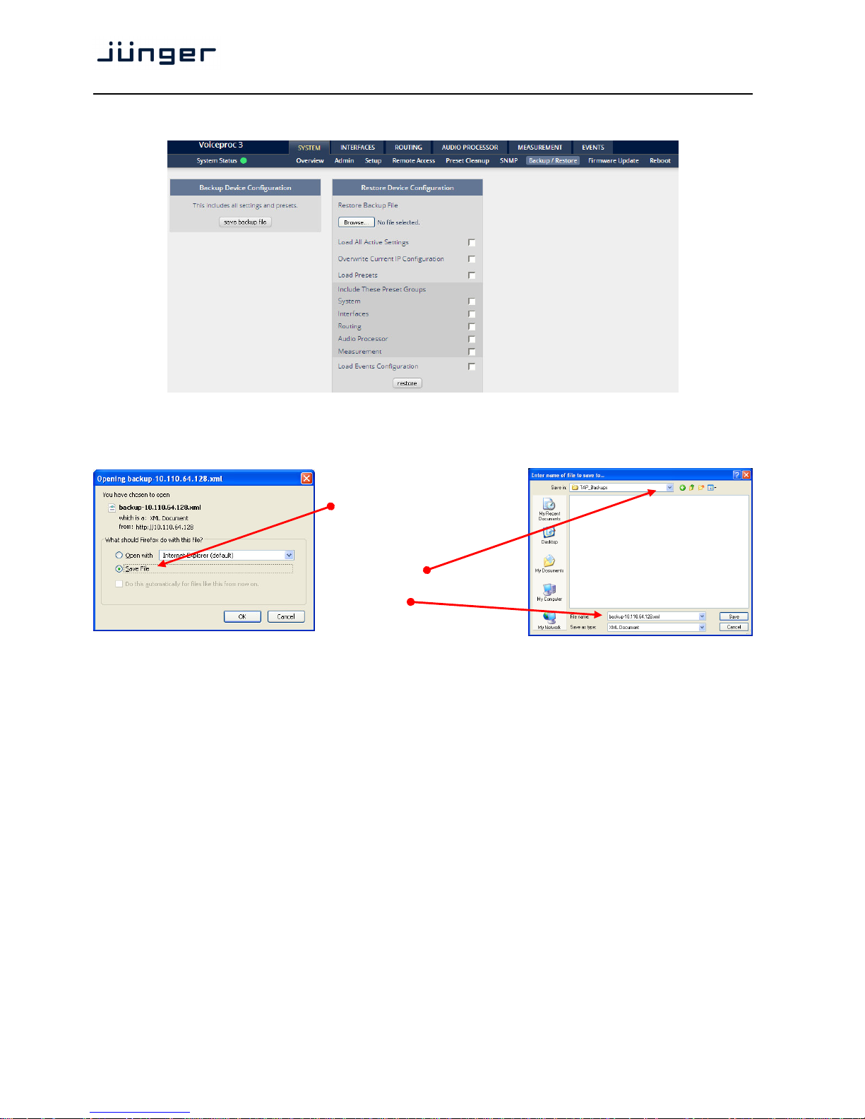
Here you can back up the complete device and restore parts or all of it. If you press <back up> the
device controller will collect all necessary data and assemble it to an XML file.
Finally you will get a pop up message:
You must select:
<Save File>.
After pressing <OK>, the
system file dialog opens:
Select a folder
and alter the default file name
if needed.
Similar applies to the restore process. You must select the desired backup file which you want to restore
and check the necessary option(s) under "Restore Device Configuration".
Page 29
D*AP4 VAP
25
Setup GUI – SYSTEM – Firmware Update
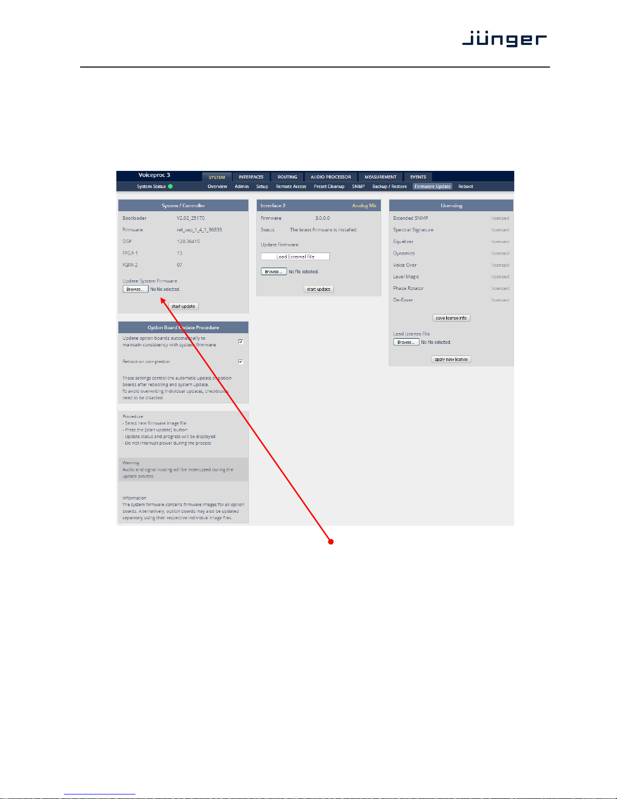
The files to update the D*AP4 VAP will be available in ZIP format. You must unpack them to your PC in
order to access them for the update procedure.
You will find an image file for the D*AP4 VAP core system in the format (example):
"rel_vap_1_0_1-26328.img" as well as update files for components, like the optional interface boards
in the format: "rsdi150_v51.sdi" or for the X*AP RM
1
remote panel.
To update the D*AP4 VAP, you must <Browse …> to find the respective firmware file (which you
have unzipped before) and press <start update>. After finishing the procedure the device will
automatically reboot.
You may also update the firmware of an installed SDI board (Interface 1) or an Analog Mic board
(Interface 2). The respective file(s) have been uploaded together with the system firmware so you can
select an update file form the Update Firmware pull-down box. In case you provide an extra file you
must select the option: "Load External File".
Finally you can see the options of your device which you have bought a license for. When you buy a
license you must provide the license info file and you in return will get a new license file which you
must apply to the device here.
Page 30
D*AP4 VAP
26
Setup GUI – SYSTEM – Reboot
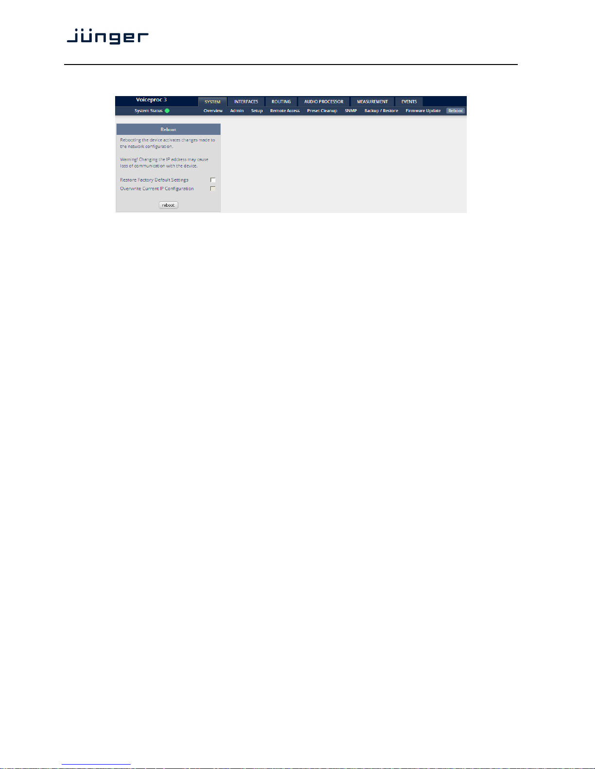
Restore Factory defaults Will clean up the parameter and preset memory and will initialize all
parameters to their factory default values and will reset passwords
and turn authentication off.
Overwrite Current IP You may exclude the current IP settings from this process
IP Configuration to keep your existing settings.
Page 31
D*AP4 VAP
27
Setup GUI – INTERFACES – AES I/O
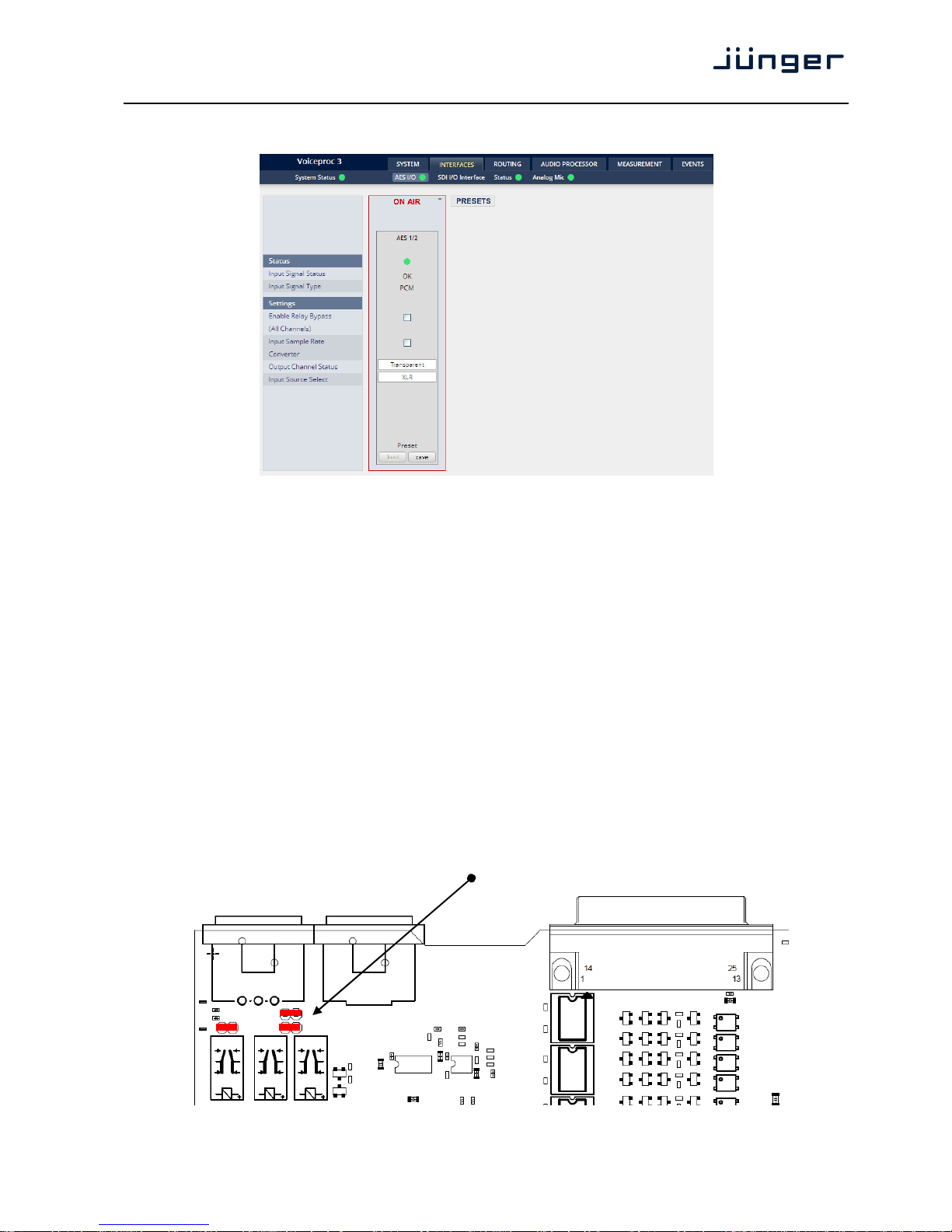
Status [red / green]
Input Signal Status [OK / Fail]
Fail = no carrier, unlock, cranky [too much jitter]
Input Signal Type [Mute / PCM / Non PCM]
The Non PCM (e.g. Dolby encoded signal) status will be retrieved
from a logical combination of the validity flag and the channel status.
Important Note! The input signal status is logically combined and represented as part of the
System Status. If one of the inputs is not assigned by the ROUTING matrix, its status will not be
incorporated into the System Status. If non of the inputs is routed the Interface Status > AES I/O status soft
LED becomes grey.
Settings
Enable Relay Bypass [ON / OFF]
(All Channels) .
Input Sample Rate For asynchronous sources it is possible to turn a SRC on.
Converter If a SRC is turned on and the input status becomes Non-PCM, the
SCR will be turned OFF automatically in order to maintain the
original data structure of the encoded bit stream (e.g. Dolby E).
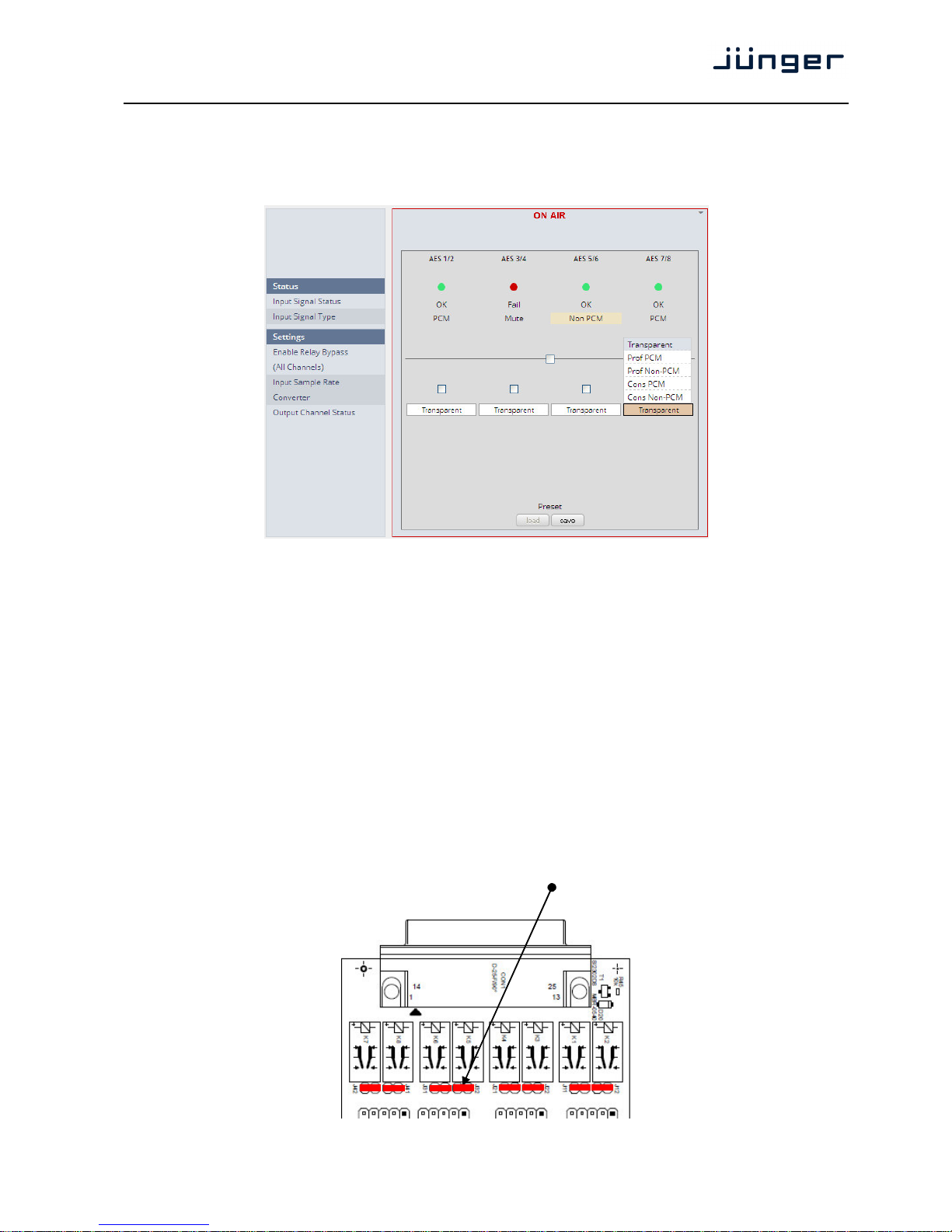
Important note! The AES relay bypass circuit of the AES I/Os may be deactivated inside the VAP.
You must open the cover plate from the VAP unit and locate the jumper shown in the schematic below:
You must remove the jumpers to de-activate the AES I/O relay power fail circuit.
Page 32
D*AP4 VAP
28
Output Channel Status [Transparent / Prof. PCM / Prof Non-PCM /
Cons. PCM / Cons. Non-PCM]
The channel status can either be
transparent from the input source
of the D*AP4 VAP or may be overwritten.
Input Source Select [XLR]
The D*AP4 VAP has an XLR input only.
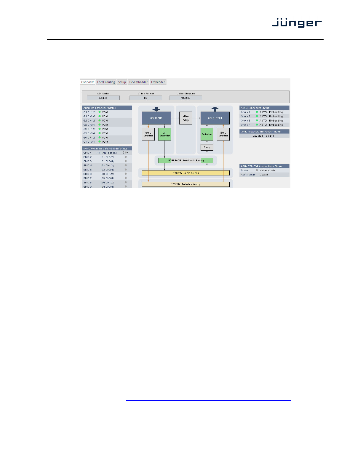
Setup GUI – INTERFACES – Analog Mic
Setup
Input [Mic / Line]
Enable Preamp Gain [ON / OFF]
Preamp Gain (dB) [10 … 65]
Pad (dB) [OFF / -10]
Phantom Power [ON / OFF]
Phantom power is
available when
Input = Mic
is selected.
Page 33
D*AP4 VAP
29
Setup GUI – INTERFACES – SDI I/O interface – Overview
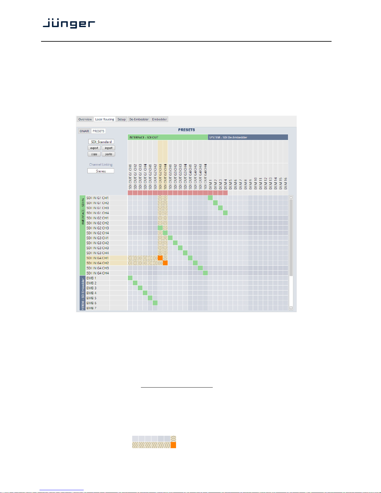
If the D*AP4 is equipped with an optional SDI interface the following settings will be available.
This pane has five sub panes embedded:
The overview pane shows all relevant information of that interface:
SDI Status [Locked / Unlocked]
Video Format [SD / HD /3G / N/A]
Video Standard [actual decoded standard (e.g. 1080i50) / No SDI Lock]
Audio De-Embedder [PCM / Dolby E / Dolby Digital / Dolby Digital Plus / MPEG-4 HE AAC /
Status MPEG-4 AAC / N/A]
VANC Metadata The respective soft LED will turn green to indicate the SDID found in the stream
De-Embedder Status while the angle brackets indicate the SDID one has selected in the de-embedder
set-up as a pre-selected stream.
Audio Embedder [AUTO – Embedding / AUTO – Replace Audio / OFF / Delete]
Status
Group 1 – 4 The embedding process distinguishes between 4 different modes for each
group independently:
Embedding – a new group will be built
Replace – the structure of the group from the input is kept and the audio
content is simply replaced
Delete – the group from the input is deleted
OFF – the embedder from that group is turned off
VANC Metadata [Enabled / Disabled & selected SDID#]
Embedder Status For details see SMPTE 2020-2 standard.
ARIB STD-B39 Meta information standard.
Control Data Status
Status [Available / Not Available]
Audio Mode See ARIB Japanese standard "Structure of Inter-Stationary Control Data
Conveyed by Ancillary Data Packets"
http://www.arib.or.jp/english/html/overview/doc/2-STD-B39v1_2.pdf
Page 34
D*AP4 VAP
30
Setup GUI – INTERFACES – SDI I/O interface – Local Routing
The SDI interface comes with a local routing matrix to shuffle audio signals from and to the system (device)
(i.e. to and from the central device router) and from and to the physical de-embedders / embedders.
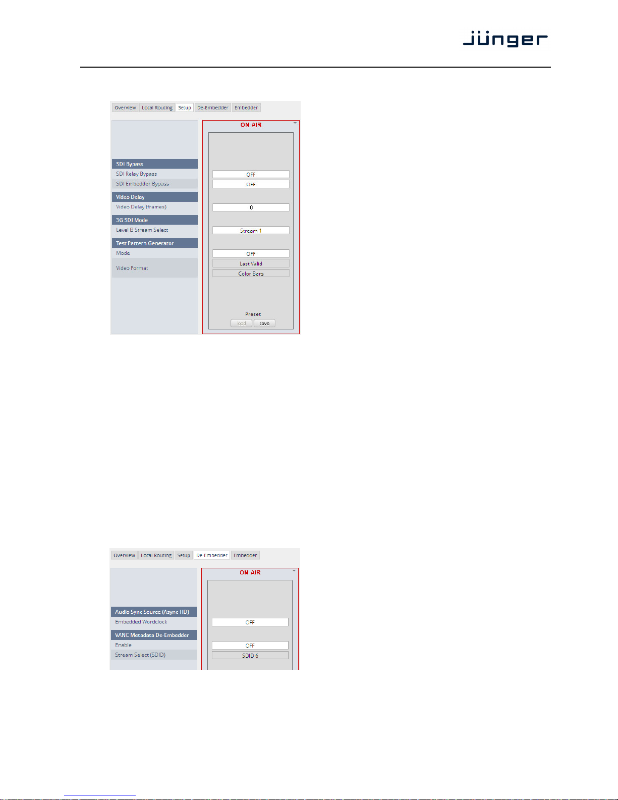
Below you see an example routing that sends all signals 1:1 from the physical de-embedders
[INTERFACE – SDI IN G2 CH3 … SDI IN G4 CH4] to the physical embedders [SDI OUT G2 CH3 …
SDI OUT G4 CH4]. The signals from the physical de-embedders [SDI IN G1 CH1 … SDI IN G1 CH4] are
sent to the device router [DEM 1 … DEM4] while the device router outputs [SYSTEM – SDI Embedder
EMB 1 … EMB 6] are routed to the first 6 SDI channels [SDI OUT G1 CH1 … SDI OUT G2 CH2]:
You must use the scroll bar to navigate through the matrix. In the upper left corner you can select between
the ONAIR and the PRESETS view of the matrix. On the ON AIR page you will also see the device signal
labels (see ROUTING section further below for details).
Channel Linking [mono / stereo]
You can decide if the routing must be performed in mono or stereo mode
(where adjacent odd/even channels are routed at once).
You may select cross points by hovering with the mouse over the little squares and select / deselect cross
points with a left mouse button click. The color of the respective squares changes:
Mouse over Color codes of cross points:
dark blue Possible new cross point.
orange You are about to reconnect a cross point.
grey Cross point is not allowed
(i.e. routing will cause a loop and will not therefore be performed).
red You are about to disable a cross point
An animated signal flow will help you when navigating through the matrix.
Page 35
D*AP4 VAP
31
Setup GUI – INTERFACES – SDI I/O interface – Setup
SDI Bypass
SDI Relay Bypass Will deactivate the Bypass
Relay. It provides a shortcut from
SDI-IN to SDI-OUT1 and
disconnects the de-embedder
from the SDI input. This relay
also serves as a fail bypass if
the power is off. This feature
maintains the SDI signal for
downstream equipment.
SDI Embedder Will pass the embedded audio
Bypass data from the de-embedder to the
embedder 1:1. This function
preserves the original
ancillary data structure.
Video Delay
Video Delay [0 … 15]
(frames) For compensation of any kind of
audio processing delay within the
chain of devices you may use a
Video Delay. Position “0” turns
off the delay function.
3G SDI Mode
Level B Stream A 3G-SDI signal may have two HD sub streams (e.g. for 3-D TV),
Select AKN as 3G-B standard select between stream 1 or 2 for embedded
audio. See SMPTE 425M for details.
Test Pattern Generator The interface offers a test generator to either check downstream
connections during installation or for use in case of an input fail but you
may also use it to move 16 independent audio channels over a single
coax cable from point to point.
Mode [OFF / AUTO (Input Loss) / Always ON]
Video Format [Last valid / one of the defined SD / HD 3G formats (see specs)]
[Color Bars / Black Frame]
Setup GUI – INTERFACES – SDI I/O interface – De-Embedder
Audio Sync Source The HD SDI standard allows
(Async HD) for asynchronous audio. This is
critical if you have decided to
synchronize the device on such
signal. Here you find a solution.
You may either use the
embedded word clock or the SDI
carrier itself as a reference.
Embedded Word [Auto / De-Embedder CH1
Clock (DEM 1) / OFF]
OFF = synchronized to the
SDI carrier.
Auto = In case of asynchronous audio it is synchronized automatically
to the SDI carrier.
DEM1= From de-embedder group 1 channel 1.
Page 36
D*AP4 VAP
32
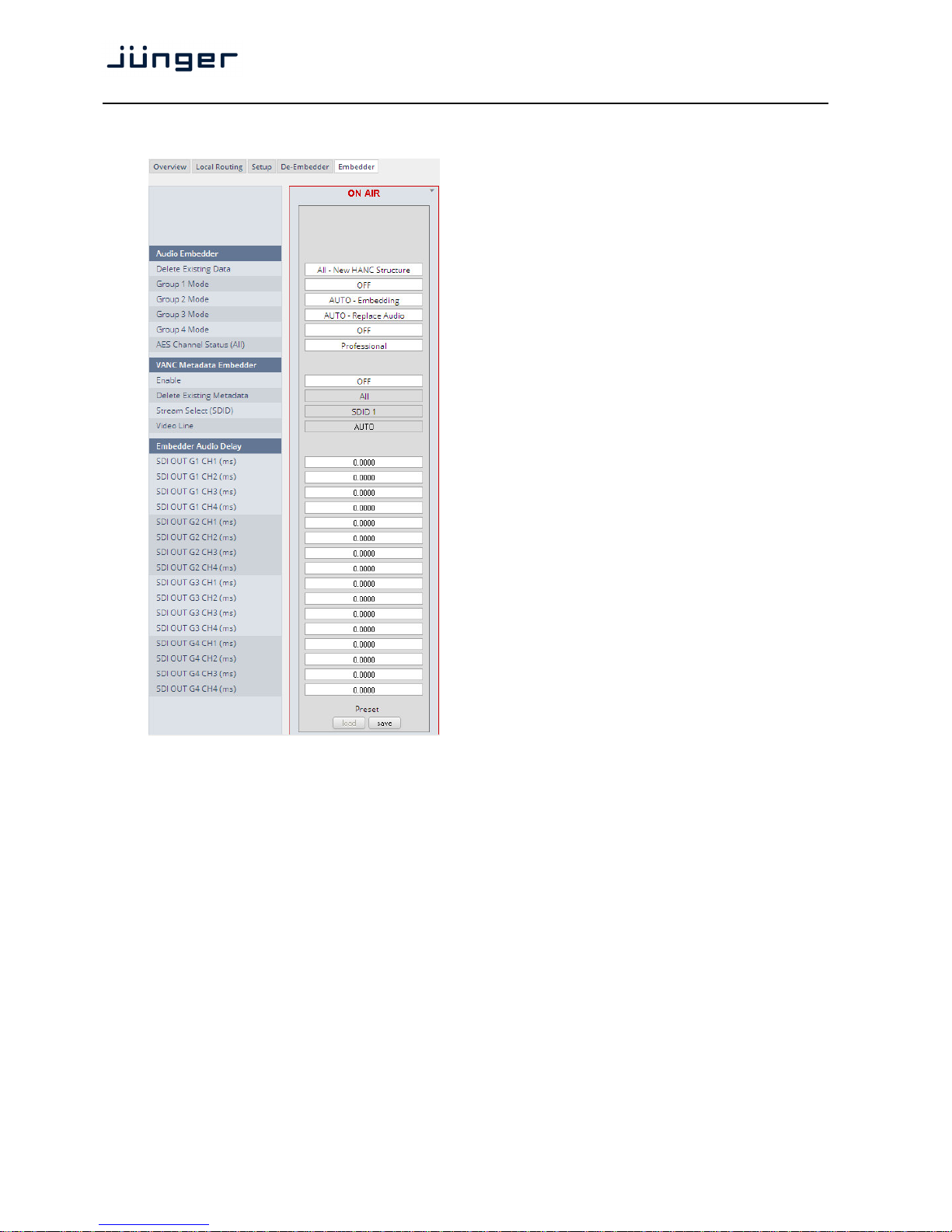
Setup GUI – INTERFACES – SDI I/O interface – Embedder
Audio Embedder Here you set the general
functions of the embedder
Delete Existing Data [ALL – New HANC Structure
/ OFF]
Group 1 – 4 Mode [OFF / AUTO – Embedding
/ AUTO – Replace Audio
/ Delete]
See SDI I/O Interface > Overview
for details.
AES Channel [Transparent / Professional]
Status If Professional these values are
used:
Format: Professional
Audio Mode: [Audio / Non
Audio]
Emphasis: None
Freq. Mode: Locked
Sample Freq.: 48kHz
Channel Mode: Not Indicated
User Bits: None
Auxiliary Bits: 24Bit
Audio Word
Length: Not indicated
Important note! If you generate a new AES channel
status the Audio Mode will be automatically set to Non
Audio (AKA "other") for both channels, if an adjacent pair
(1/2, 3/4 …..) carries a Dolby E stream for example.
VANC Metadata The embedder can insert one
Embedder Dolby metadata stream into the
Vertical Ancillary Data
Enable [ON / OFF]
Delete Existing [AII / OFF]
Metadata
Stream Select [SDID 1 … SDID 9]
(SDID)
Video Line [Auto / 9 … 44]
The line number depends on the actual video standard how many VANC
lines are available for data insertion.
Embedder Audio Each embedder signal may be delayed independently. This may be useful
Delay for Lips Sync alignment if a video delay is used.
Important Note! You must take care that for Dolby encoded signals the adjacent pairs must be set to the
same delay values not to destroy the data structure.
SDI OUT G1 CH1 (ms) [0.0000 … 340.000]
to
SDI OUT G4 CH16 (ms) [0.0000 … 340.000]
Page 37
D*AP4 VAP
33
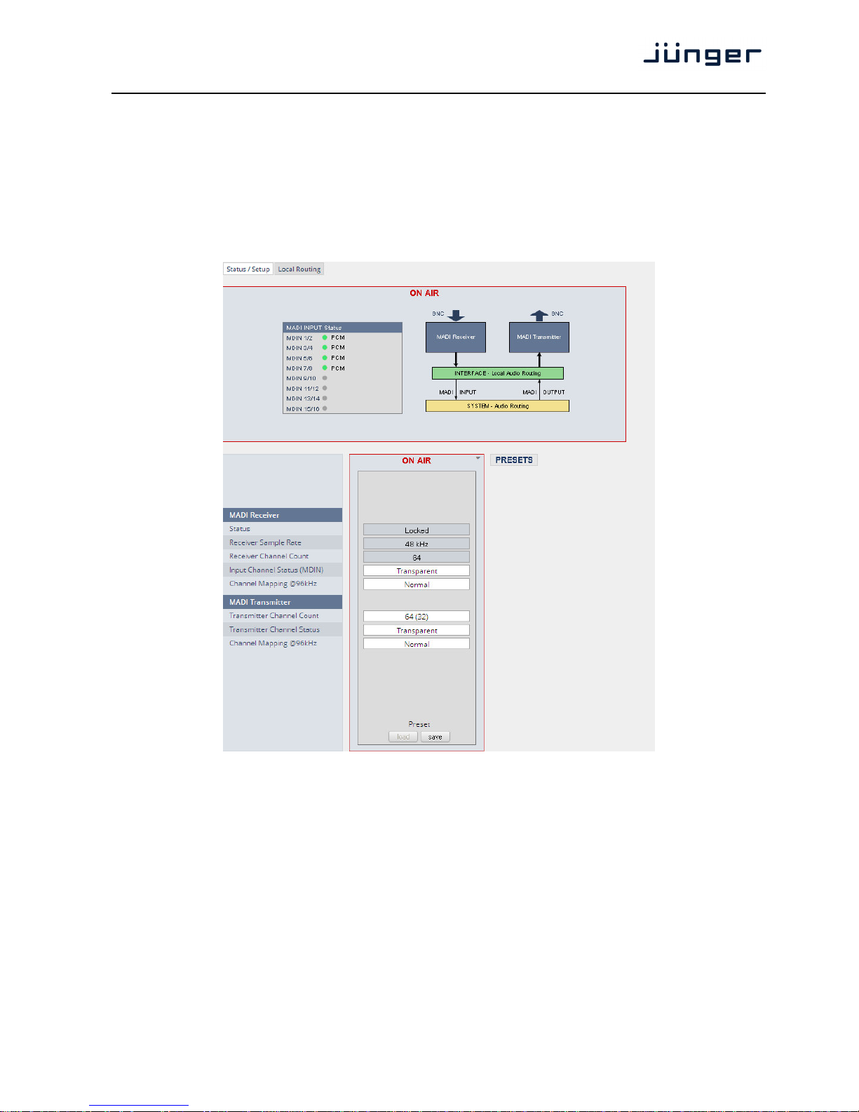
Setup GUI – INTERFACES – MADI Interface – Status / Setup
The implementation of MADI for the V*AP is based on the option module O_DAP_MB (BNC) or
O_DAP_MO_MM (MADI optical multi mode fiber) or O_DAP_MO_SM (MADI optical single mode fiber).
Since the V*AP is a four channel processing device not all 64 MADI channels are available for device I/O.
The first eight channels are available via the MADI local router to the device router.
They appear at the device router pane as MDIN 1 .. 8 and MDOUT 1 … 8.
These channels can be routed to and from any of the local routing sources MADIRX 1 … 64
and MADITX 1 … 64 respectively.
MADI Receiver
Status [Locked / Locked-Async / Error]
The timing of the audio decoding is locked to the MADI clock. If the
internal timing of the VAP is different "Locked-Async" is displayed.
Receiver Sample Rate [44.1 / 32 / 48 / 88.2 / 96Hz / Unknown]
The measured sample rate from the received MADI stream.
Receiver Channel Count [32 / 56 / 64]
Depends on the upstream MADI transmitter settings.
Input Channel Status (MDIN) [Transparent / Professional]
One may overwrite the input channel status by a set of professional
ones.
Channel Mapping @ 96 kHz [Normal]
Page 38
D*AP4 VAP
34
MADI Transmitter
Transmitter Channel Count [64 (32) / 56 (28)]
Depends on the internal sample rate and the desired number of
MADI channels. The numbers in brackets are valid for 96kHz.
Transmitter Channel Status [Transparent / Professional]
Channel Mapping @ 96 kHz [Normal]
The connection for fiber cable is made by a LC connector. Looking at the rear panel the transmitter is
the left one and the receiver the right one.
Setup GUI – INTERFACES – MADI Interface – Local Routing
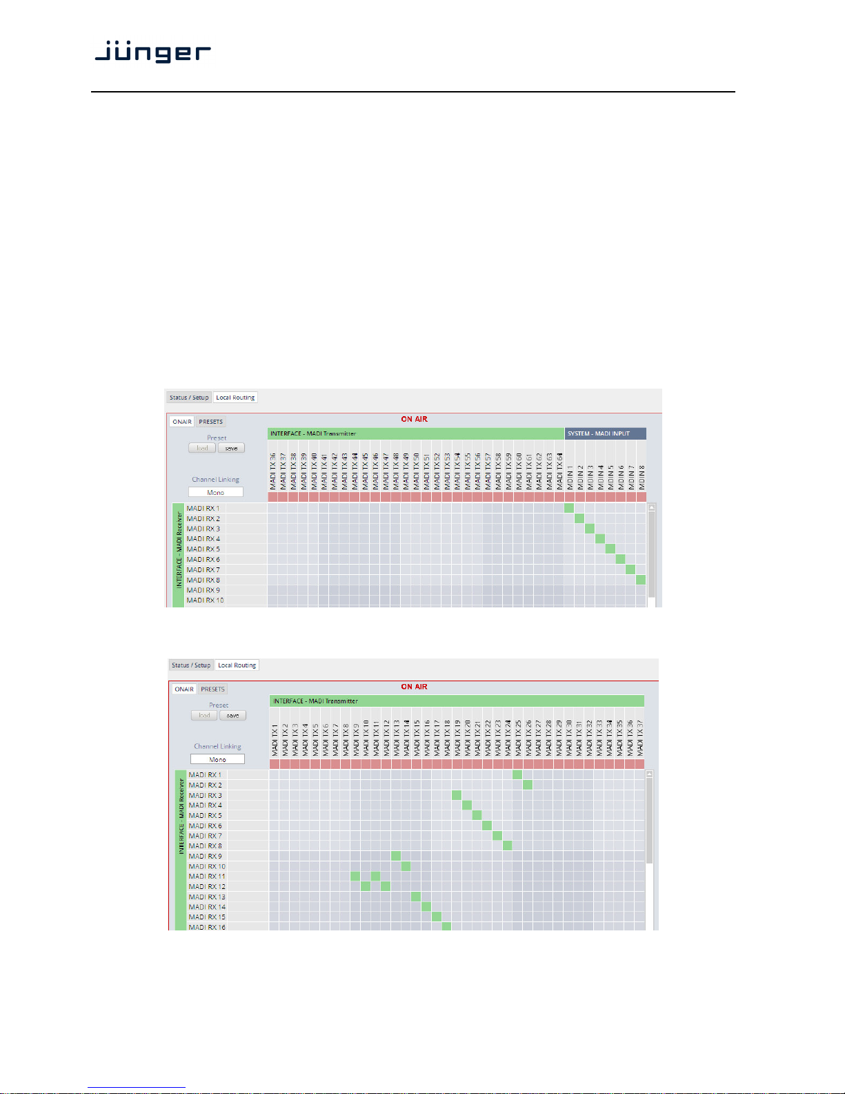
Below are some excerpts from the local routing pane. Single channels from or to the VAP may be
connected with the MADI transmitter or MADI receiver respectively.
The example below shows the first 8 MADI channels from the receiver (MADI RX 1 … MADI RX 8)
connected with the device inputs SYSTEM MADI INPUT (MDIN 1 … MDIN 8):
The Local Routing pane can also be used to route MADI signals from the receiver directly to the
transmitter and vice versa:
Page 39
D*AP4 VAP
35
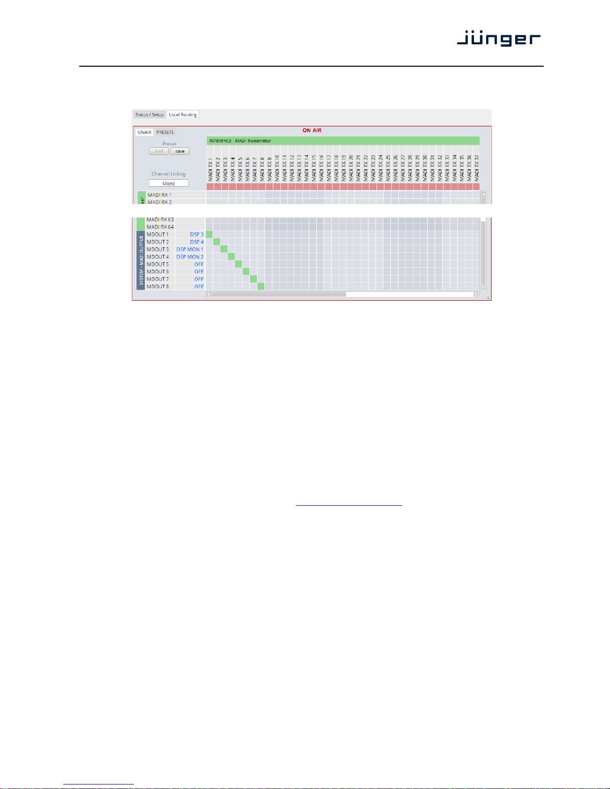
You can also assign device outputs (MAOUT 1 … MDOUT 8) to MADI transmitter channels
(MADITX 1 … MADITX 8). For better visibility the matrix has been divided by cutting off the middle part:
----------------------------------------------------------------------------------------------------------------------
You must use the scroll bars to navigate through the huge matrix.
Setup GUI – INTERFACES – Dante I/O Interface – Status
The DANTE interface connects a D*AP4 VAP to an audio over IP (AoIP) network. Junger Audio has
committed itself to the quasi industry standard DANTE developed by the company Audinate.
"Based on industry standards, Audinate created Dante, an uncompressed, multi-channel digital media
networking technology, with near-zero latency and synchronization … One cable does it all. Dante does
away with heavy, expensive analog or multicore cabling, replacing it with low-cost, easily-available
CAT5e, CAT6, or fiber optic cable for a simple, lightweight, and economical solution. Dante integrates
media and control for your entire system over a single, standard IP network."
The network infrastructure for AoIP must be able to handle the IP multicast. The recommendation is to
separate the control network from the audio network.
For details pls. refer to the Audinate web-site:
https://www.audinate.com. Here you will find many useful
application videos and FAQs.
To configure such an audio network you need the DanteController software. You can download it from
the Audinate web site. If you want to interface a PC or MAC to such an audio network you can use the
VirtualSoundcard software from Audinate. It provides standard audio drivers to connect with common
sound tools.
We highly recommend reading the Audinate documents to understand how to set-up and operate
a real-time AoIP network.
Looking at the rear panel the RJ45 connector on the left is the primary port while the second connector
acts either as a redundant or as a switch port. Both RJ45s have built in LEDs. The left one shows
network activities (flashing green) while the right one indicates the interface speed,
with green=1Gbit/s and off=100MBit/s.
Page 40
D*AP4 VAP
36
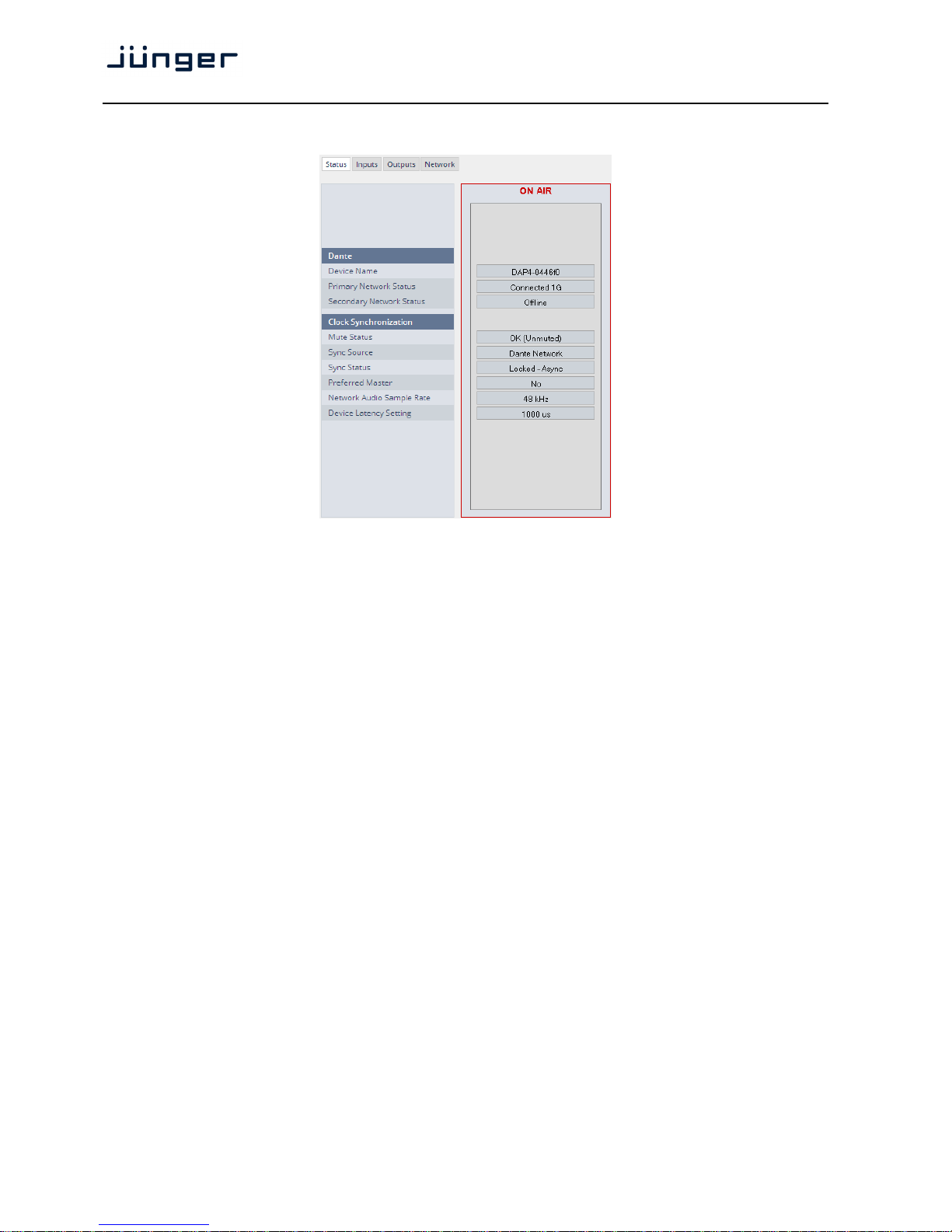
Below is the Status page of the DANTE interface board:
The parameters you see here must be set via the DanteController software.
Dante
Device Name The name you gave the interface board via the DanteController.
Primary Network Status [Offline / Connected + bandwidth]
Secondary Network Status [Offline / Connected + bandwidth]
Clock Synchronization
Mute Status [OK (Unmuted) / Muted]
Sync Source [Dante Network / DA*P is Master]
Here you define the reference clock for this DANTE module.
Important Note! If this parameter is set to "Dante Network", the D*AP must be synchronized to the same
clock as the network clock master (whoever it is). It must be set to "Dante Network" if this module is to
become the "Preferred Master" of the network.
Sync Status [Unlocked / Locked / Locked-Async]
The sync source for the DANTE interface is the DANTE network.
If no network cable is connected the interface is "Unlocked". If it is
connected to a network it will be "Locked". If the D*AP VAP is set to
synchronize to other than the DANTE interface it will show
"Locked-Async".
Preferred Master [No / Yes]
The Dante algorithm automatically looks for the best clock master
inside the network but one may force a DANTE module to become
the clock master.
Network Audio Sample Rate [44.1kHz / 48kHz / 88.2kHz / 96kHz]
Depending on the A*P device type the sample rate is limited to the
device specification.
Device Latency Setting [1000 µs]
You can allow for a certain transmission latency if you face network
problems of any kind.
Page 41
D*AP4 VAP
37
Setup GUI – INTERFACES – Dante I/O Interface – Inputs
The DanteController software gives you an overview of all members of such a DANTE network.
You can assign channel labels for the inputs (from the network to the device interface). Those labels will
automatically appear in the D*AP VAP and will be displayed there.
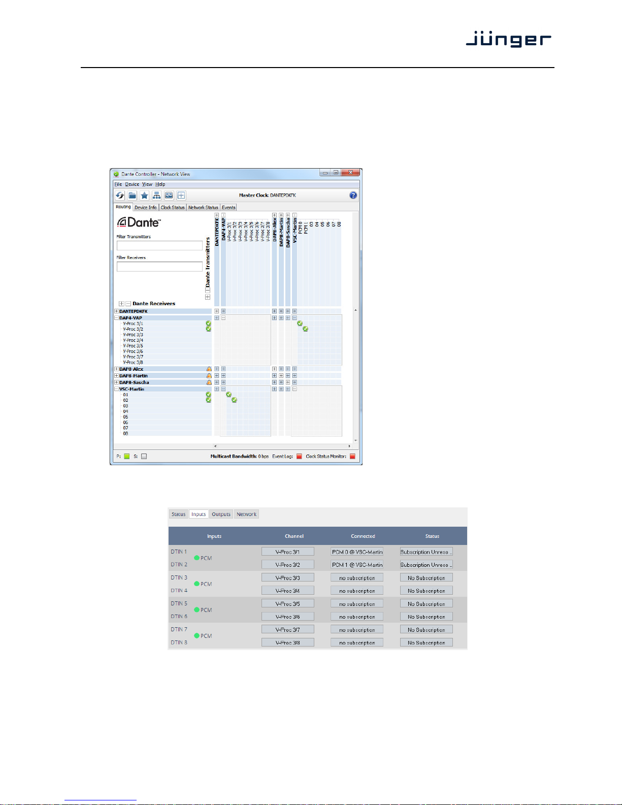
Here is a glimpse on the GUI of the DanteController:
As an example you see here a
"DAP4-VAP" (name given by the Dante
Controller) that has assigned the labels
V-Proc 3/1 … 3/8 for both the inputs and
the outputs.
Beside a few more devices on that
network, we see the unfolded outputs
of a DanteVirtualSoundcard (VSC)
named "VSC-MARTIN" on the upper
right hand side.
The top horizontal area shows the
transmitters while the receivers are
shown vertically on the left hand side.
The outputs PCM 0 and PCM 1 from the
VCS are assigned to the VAP inputs
V-Proc 3/1 and 3/2 while two outputs
from the "DAP4-VAP" are assigned to
the VSC inputs "01" and "02".
We see the labels assigned by the DanteController software in the "Channel" column:
Inputs Eight inputs are pre-defined for the DANTE interface installed in a
D*AP4 VAP. They are organized in pairs and the input status is
shown by soft LEDs (green = PCM audio / yellow = non audio/ grey
no audio).
Page 42
D*AP4 VAP
38
Channel The labels assigned to that channel by the DanteController
Connected The source of the audio signal.
Status [No Subscription / Subcription Unresolved / Wait / Naming Problem /
Loopback / Idle / Subscription in Progress / Connected (Unicast) /
Connected (Multicast) / Manual Config / Format Problem /
QoS Problem / Latency Problem / Clock Domain Problem /
Link Down / Fail / Unknown]
The DANTE module provides very detailed status information. In
regular operation one will not see much of it.
Setup GUI – INTERFACES – Dante I/O Interface – Outputs
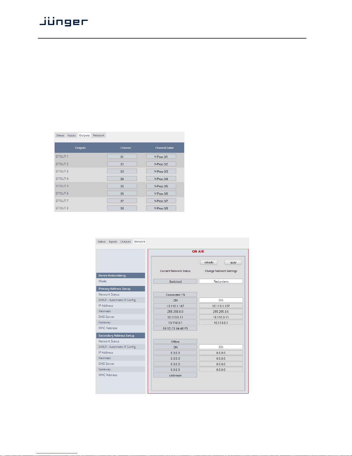
Outputs The signals from the DANTE
board to the network. They will
also appear in the device
ROUTING section.
Channel Numeric count of the channels.
Channel Up to eight labels can be
Label configured for each stream from
the interface to the network. This
allows configuring multi layer
routing.
Setup GUI – INTERFACES – Dante I/O Interface – Network
Dante Redundancy The DANTE interface allows redundant network operation.
Pls. refer to manufacturer's documentations of your Ethernet
equipment on supported switching configuration and redundant
operation.
Page 43

D*AP4 VAP
39
Mode [Switched / Redundant]
Redundant – The interface will duplicate the audio traffic to both
Ethernet ports.
Switched – The second port behaves like a standard switch
port allowing daisy-chaining through the interface.
I.e. IP configuration is only available for Redundant
mode.
Important Note! When set to switched mode, do
not connect both ports to the same network
(same Ethernet switch) if it does not support STP (Spanning Tree Protocol). This is the case for most of
the off-the-shelf (office) switches. Doing so will cause a race condition where IP packets are circling around
from the external switch to the second Dante (switch) port and back via the first port. This will tear down
your network and may create a bunch of new "friends" in your facility.
Primary Address Setup Setup of the primary network interface
Network Status [Offline / Connected + bandwidth]
DHCP – Automatic IP Config. [OFF / ON]
IP-Address
Netmask
DNS Server
Gateway
MAC Address
Secondary Address Setup Setup of the secondary network interface
Network Status [Offline / Connected + bandwidth]
DHCP – Automatic IP Config. [OFF / ON]
IP-Address
Netmask
DNS Server
Gateway
MAC Address [unknown / address]
Page 44
D*AP4 VAP
40
Setup GUI – INTERFACES – 4 Ch ANALOG I/O Interface
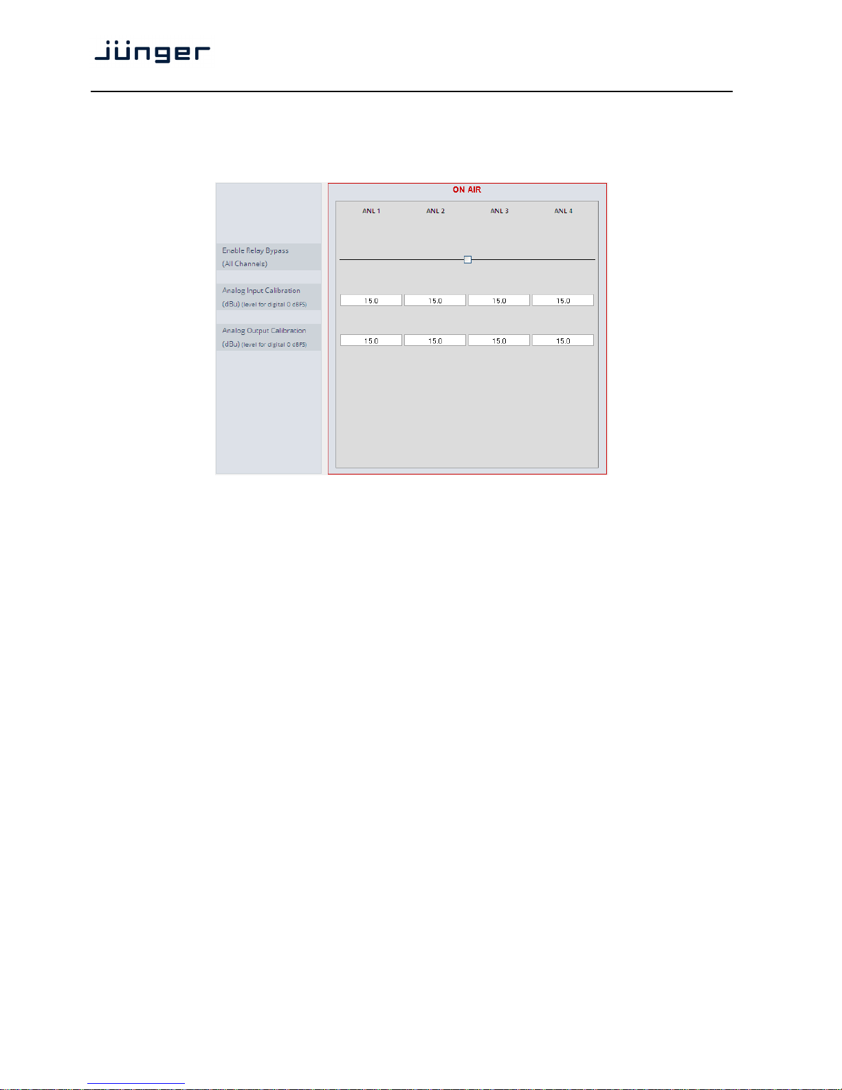
An additional analog interface can be installed in the Interface slot.
It provides 4 additional analog line inputs and outputs on a 25pin D-Sub connector:
Enable Relay Bypass [ON / OFF]
(All Channels) Power fail bypass relay that may be activated from the GUI
Analog Input Calibration [0 … 15.0 … 24.0]
(dBu)
(level for digital 0dBFS)
A/D conversion parameter. It defines the analog input level indBu to
reach a digital full scale signal.
Analog Output Calibration [0 … 15.0 … 24]
(dBu)
(level for digital 0dBFS)
D/A conversion parameter. It defines the analog output level indBU
for a digital full scale signal.
Page 45
D*AP4 VAP
41
Setup GUI – INTERFACES – AES Interface – Status / Setup
An additional AES3 interface can be installed in the Interface slot.
It provides 4 additional AES3 inputs and outputs on a 25pin D-Sub connector:
Status
Input Signal Status green [OK] / red [Fail]
Input Signal Type [Mute / PCM / Non PCM]}
Settings
Enable Relay Bypass [ON / OFF]
(All Channels) Power fail bypass relay that may be activated by the GUI
Input Sample Rate [ON / OFF]
Converter
Output Channel Status [Transparent / Prof PCM / Prof Non-PCM / Cons PCM /
Cons Non-PCM]
Controls the channel status for the AES output. It provides a set of
useful channel status information (e.g. to prevent non audio signals
to be fed to speakers).
Important note! The AES relay bypass circuit of the I/Os is activated on the option board. It is possible to
deactivate it if necessary. You must open the cover plate of the D*AP4 VAP unit and locate the jumper
shown in the schematic below. You must remove the jumpers to de-activate the AES I/O relay
power fail circuit.
Page 46
D*AP4 VAP
42
Setup GUI – ROUTING
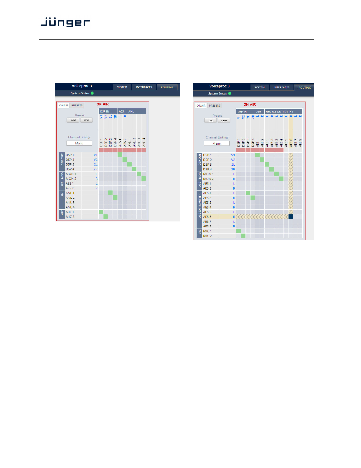
This is the core of the D*AP4 VAP as it defines the audio signal flow inside the device. It appears differently
depending on the type of optional interface boards installed.
Example for an analog interface board: example for an AES interface board:
Each functional block of the device has a source label and a destination label. Additional
blue signal
labels give an indication of the type of signal that is expected or issued by the respective function block
or I/O interface (e.g.
L/R for AES or 2L/2R for DSP 3/4 and so forth).
Top / horizontal (column headlines) = signal destinations
DSP [DSP 1 … DSP 4]
The DSP inputs carrying the signal type labels
V1, V2, 2L, 2R
where
V1/V2 indicate the voice channel input and 2L/2R the program
path input (see AUDIO PROCESSOR > Overview).
AES [AES 1 / AES 2]
The AES output of the device.
Left hand / vertical (line headlines) = signal sources
MIC [MIC 1 / MIC 2]
The inputs of the optional mic interface.
AES [AES 1 / AES2]
The AES input.
MON [MON 1 / MON 2]
The audio processor (DSP) has an independent monitor output.
It may be connected with the internal processing blocks.
(see AUDIO PROCESSOR > Overview)
DSP [DSP 1 … DSP4]
The DSP outputs carrying the signal type labels
V1, V2, 2L, 2R
where V1/V2 indicate the voice channel and 2L/2R the program output.
Page 47
D*AP4 VAP
43
The routing example on the left hand side shows both mic inputs connected to the voice channel inputs
V1/V2 of the DSP. The analog input ANL1 / ANL2 is connected to the DSP program input while the DSP
voice channel outputs
V1/V2 are connected to the AES output and the DSP program output 2L/2R and the
DSP monitor output
L/R are connected to the analog outputs ANL 1 … ANL 4.
Important Note! If a different optional interface board is installed the matrix will be expanded by the
pre-defined number of I/Os with their labels:
SDI [O_DAP_SDI_a] DEM 1 … DEM 16 and EMB 1… EMB 16
MADI [O_DAP_MB_a / MDIN 1 … MDIN 8 and MDOUT 1 … MDOUT 8
O_MO_MM_a / _MS_a]
DANTE [O_DAP_DANTE_a] DTIN 1 ... DTIN 8 and DTOUT 1 ... DTOUT 8
4 Ch ANALOG I/O [O_DAP_ADDA_a] ANL 1 … ANL 4 and ANL 1 … ANL 4
AES [O_DAP_AES_a] AES 1 … AES 8 and AES 1 … AES 8
Mouse over Pls. see "Setup GUI – INTERFACES – SDI I/O interface – Local Routing"
for details.
Setup GUI – AUDIO PROCESSOR - Overview
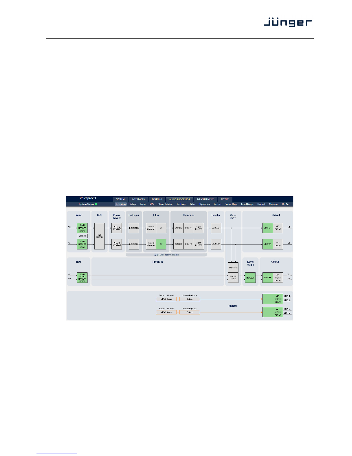
The overview shows the actual signal routing of the audio processor blocks, rendered by the DSPs.
The processing blocks in use, which may be activated from their individual setup panes, will be
indicated in green. I.e. blocks shown in grey are not activated by the user.
The order of the blocks depends on the setup of the audio processor (see next page).
To navigate through the various processing blocks you may either click on the graphical block or use
the tabs provided in the navigation bars below the bar graph displays.
Page 48
D*AP4 VAP
44
Setup GUI – AUDIO PROCESSOR - Setup
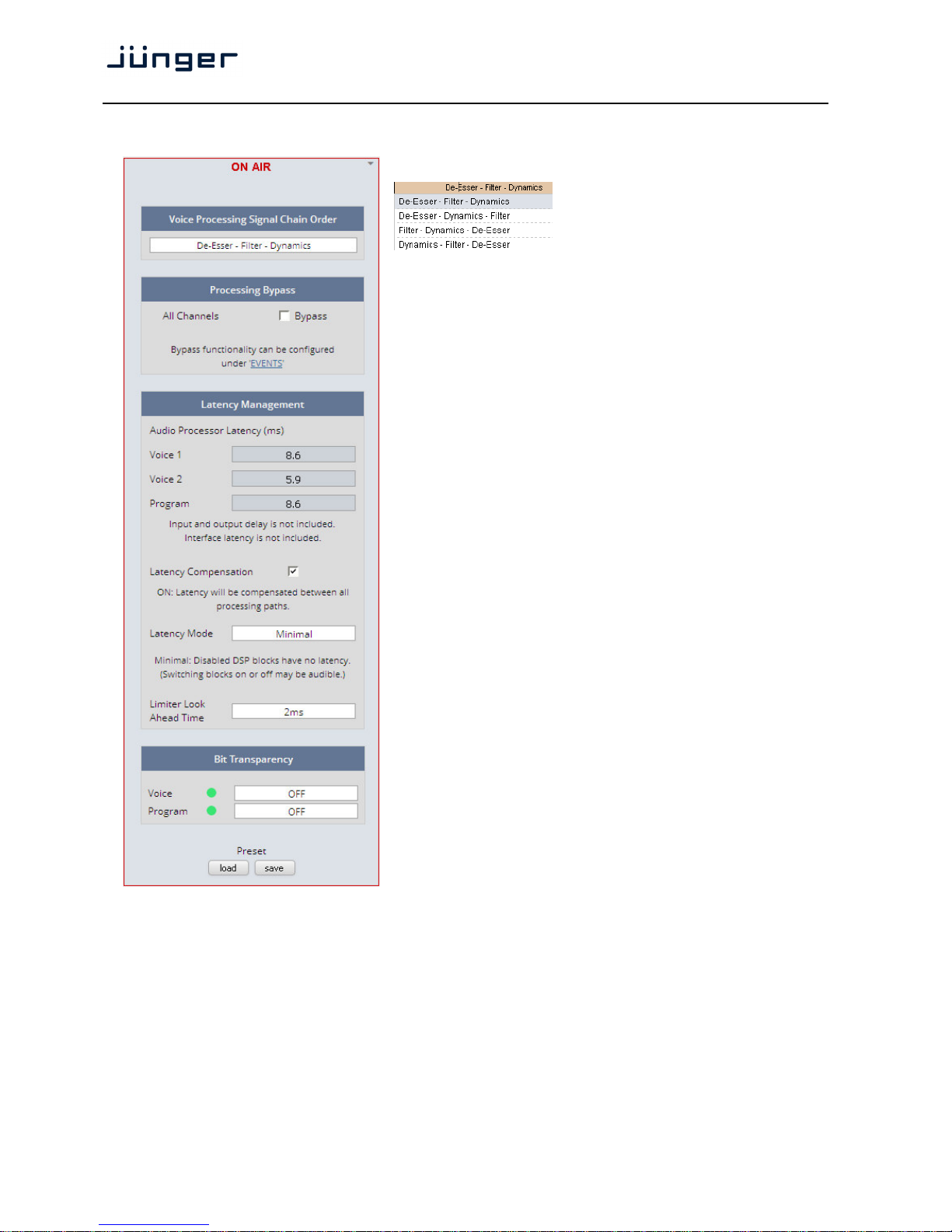
Voice Processing Signal Chain Order
The order of the processing blocks can
be re-arranged:
De-Esser, Filter, Dynamic
Individually to match your preference.
Processing Bypass [ON / OFF]
You may turn the bypass ON/OFF from
here by activating the check box.
The bypass functionality may be
configured at the EVENTS >Actions
pane where the link will direct you to.
Latency Management In a latency critical environment it might
be desirable to have the lowest possible
latency. So it is useful to actually bypass
a process that is not in use. In normal
operation, switching audio processing
modules on and off does not result in a
change of latency and thus does not
cause audible glitches or clicks.
Audio Processor
Latency (ms)
Voice 1
Voice 2
Program
Latency [ON / OFF]
Compensation "vertical" compensation to match two
channels
Latency Mode [Minimal, Nominal]
"horizontal" compensation for one
channel. Disabled audio processing
blocks are taken out of the processing
chain and are no longer causing a
delay.
However switching blocks on or off can
cause clicks and glitches, even in
unaffected channels, as the latency
compensation is recalculated.
Limiter Look [1ms, 2ms]
Ahead Time Set the True Peak Limiters Look Ahead Time to 1ms to reduce audio
latency. Full True Peak limiting is guaranteed with both settings. The
audio quality in most cases will not be affected. However, when in
doubt leave it at 2ms for assured maximum sonic performance.
Bit Transparency [OFF / ON / AUTO]
You may force the DSP to pass through the audio stream untouched
in case there is encoded audio present.
The AUTO mode is triggered by the AES channel status.
Page 49
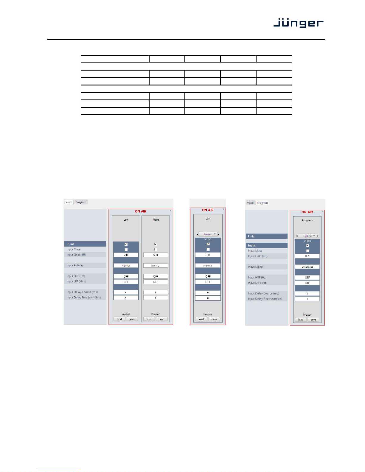
D*AP4 VAP
45
System Latency:
44.100kHz 48.000kHz 88.200kHz 96.000kHz
Base Latency
AES IN to AES OUT 3,33
3,06
2,12
2,04
Mic IN to AES OUT 4,25
3,9
2,59
2,44
Additional Latencies
Spectral Signature 2,9
2,66
2,9
2,66
Dynamics Look Ahead 2
2 2 2
Limiter Look Ahead Long 1
1 1 1
Base latency consists of 1 ms Limiter Look Ahead Time and all system inherent
processing and input/output delays.
Activating sample rate converters will add additional latency (< 1ms).
Setup GUI – AUDIO PROCESSOR – Input
You may set the input conditions for both signal paths - voice (V1 / V2) and program (2L / 2R)
via the page embedded tab sheets. The layout of the embedded "Voice" pane differs depending on
the general setup (see SYSTEM > Setup > Voice Channel Mode):
Voice Channel Mode = "2 x Mono" = "Stereo" (unlinked) Program pane:
Link [Unlinked, Linked]
This function will only be available if the voice channel is set for
"Stereo" (see SYSTEM > Setup > Voice Channel Mode).
Input [Enable / Disable]
Enables or disables the input section
Mute [ON / OFF]
Input Gain (dB) [-80.0 … 0.0 … 20.0]
Polarity (voice input) [Normal / Inverted]
Mono (program input) [L/R Stereo / L+R Mono / L/L Mono / R/R Mono]
Input HPF (Hz) [OFF / 20 / 40 / 80 / 120]
Input LPF (Hz) [OFF / 15 / 20 / 22]
Input Delay Coarse (ms) [0.0 … 2000.0]
Input Delay Fine (samples) [0 … 2000]
Page 50
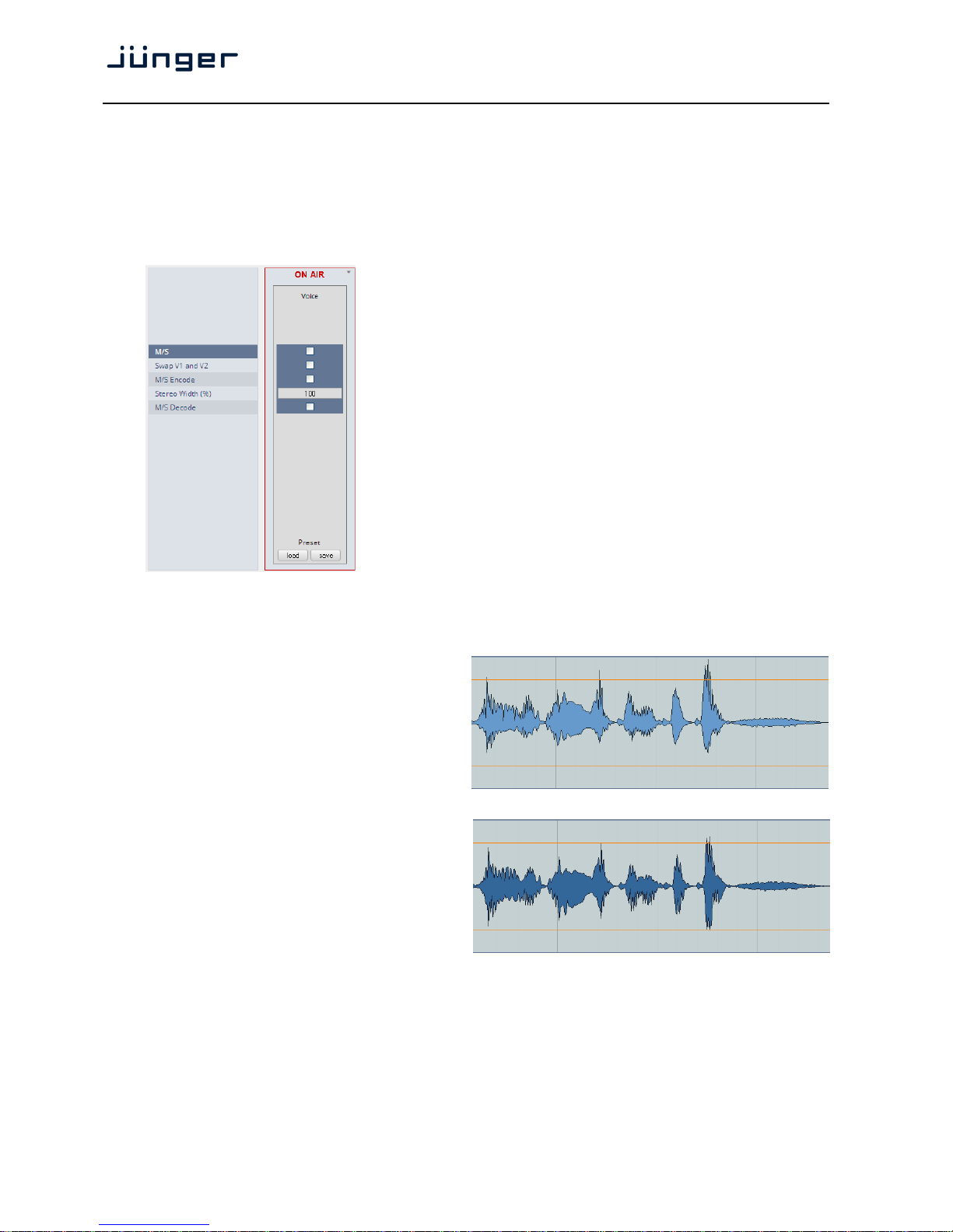
D*AP4 VAP
46
Setup GUI – AUDIO PROCESSOR – M/S
The M/S block allows for transformation of the voice channel signals from L/R to M/S and vice versa (if
you have a M/S mic connected).
The M (mid) and S (side) signals may be processed to change the stereo width from 0% (mono)
to100% (stereo) to 200% (excess width). If you want to process a L/R stereophonic signal you must first
encode it to M/S and back to L/R after width correction.
M/S [ON / OFF]
Turns the M/S block ON and OFF
Swap V1 and V2 [ON / OFF]
M/S Encode [ON / OFF]
Stereo Width (%) [0 … 100 … 200]
M/S Decode [ON / OFF]
Setup GUI – AUDIO PROCESSOR – PHASE ROTATOR
When working with human voice, one regularly
experiences issues with imbalanced waveforms.
Imbalanced in this context means that the
positive or negative half of the alternating signal
carries more power than the other.
The problematic result of this type of imbalance
is unnecessarily applied dynamics processing
(e.g. signal limiting) or loss of headroom.
The Phase Rotator detects this type of imbalance
and automatically applies a complex
phase wrapping filter to restore symmetry.
Please keep in mind that this system is not
effective against DC offset. In this case
a high pass filter should be applied instead.
Page 51
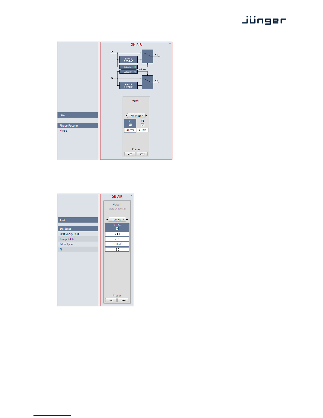
D*AP4 VAP
47
Each microphone channel has an independent
Phase Rotator.
Here the display for stereo operation but unlinked
Link [Unlinked / Linked]
For stereo operation you may
link the setup parameters of
both voice channels.
Phase Rotator [ON / OFF]
Mode [OFF / ON / AUTO]
OFF
System is inactive
ON
System always applies phase
wrapping
AUTO
Unbalanced waveforms are
automatically detected and
phase wrapping is applied only
if necessary.
Setup GUI – AUDIO PROCESSOR – De-Esser
Link [Unlinked, Linked]
For stereo operation you may link the
setup parameters for both voice
channels.
De-Esser [ON / OFF]
Frequency (Hz) [1000 … 3000 … 16000]
Range (dB) [-20.0 … 0.0]
Filter Type [Peak / High Shelf]
Q [0.4 … 1.0 … 8.0]
Important Note! For the following explanations we assume that the D*AP4 VAP is set up for
2 x Mono operation mode (see SYSTEM > Setup > Voice Channel Mode). I.e. there are always two voice
channels displayed and no link option.
Page 52
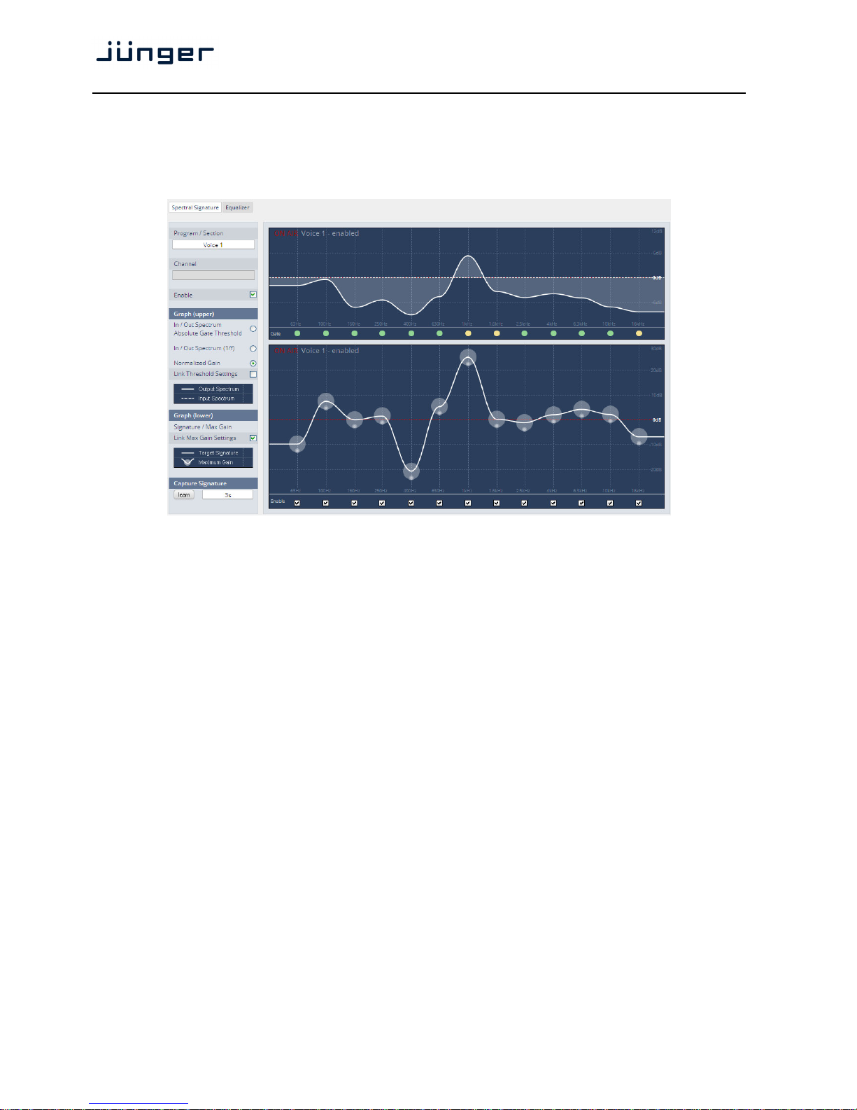
D*AP4 VAP
48
Setup GUI – AUDIO PROCESSOR – Filter – Spectral Signature
Spectral Signature is a highly sophisticated dynamic multiband filter to boost (or reduce) spectral parts
of the processed audio signal dynamically. It punches through a reference spectrum to the processed
audio signal.
Program / Section ["Left" / "Right" / Preset]
For stereo operation the name assigned to "Voice 1" will be displayed.
Selects the source for which Spectral Signature will be displayed.
This selection depends on the Voice Channel Mode
(see SYSTEM > Setup > Voice Channel Mode).
Since this view does not allow the display of a preset page side by side
as usual, one must select "Preset" to get to the preset editor.
Channel Applicable only if SYSTEM > Setup > Voice Channel Mode = Stereo.
You can select which channel must actually be displayed (see also LI
Enable [ON / OFF]
Enables / disables Spectral Signature for the selected section.
Please note: For convenient operation, this function is also available
(in the Expert section, see below) within the web interface.
Graph (upper) The upper graph is a metering window, illustrating the difference
between the input (dotted line) and the output (solid line) signal.
This window can be used in two different ways:
Input / Output Spectrum
Absolute Gate Threshold [alternative selection]
The spectrum is shown in absolute values (related to digital full scale).
This is very helpful to get an impression of the frequency response of the
signal. Also, in this mode the absolute gate threshold can be set within the
graph by grabbing and dragging the lower transparent sphere.
The gate LED row at the bottom indicates whether the absolute or
relative gate of the band is closed (yellow) or open (green). A gray LED
indicates that the band is switched out.
Normalized Gain [alternative selection]
This is very useful to see the actual amount of amplification or
attenuation within each band. In this setting the Absolute Gate
Threshold cannot be set.
Page 53

D*AP4 VAP
49
Link Threshold settings [ON / OFF]
The absolute gate threshold can be set individually for every single
band. However, in most cases this is not necessary. Checking this box
links all gate thresholds. This connection is absolute, differences
between bands will be overwritten. Please note: For convenient
operation, this function is also available in the Expert section
(see below).
Graph (lower)
Signature / Max Gain (dB) [0 … 12]
Spectral Signature does not work with an absolute level reference. Its
frequency response is based on level differences between bands only.
Thus a signature is only represented on a relative graph showing the
level positions related to the neighboring bands. In consequence,
having a straight line does not mean Spectral Signature is not doing
anything or is in a 'neutral' status. A straight line would cause Spectral
Signature to modify the input signal towards the frequency response of
white noise which is, in most cases, not desirable. To change a band,
just grab and drag the corresponding sphere. It is recommended to use
the 'Learn' function first (see below). Every single band can have an
individual max gain value that limits the maximum amplification and
attenuation. To set this value, grab and drag the smaller sphere on the
bottom of the main sphere. The max gain setting is indicated by the
size of the main sphere. The lowest and highest values are indicated by
a flashing edge.
Link Max Gain Settings [ON / OFF]
Instead of dialing in all max gain settings individually per band, this link
function is a handy tool for basic setup. This connection is absolute,
differences between bands will be overwritten.
Enable [ON / OFF]
Checkboxes on the bottom of the lower graph can be used to bypass
single bands from processing.
Capture Signature Spectral Signature is a dynamic filter tool to even out differences
between signals of different source or condition. It does not have an
absolute reference. Only if the incoming signals frequency response
equals the reference response (signature), Spectral Signature will
operate in a neutral manner. To create a reference spectrum, which is
called 'Signature', start your reference signal and hit the 'Learn' button.
After a couple of seconds (see below), the Signature is updated. If the
input signal does not change, the upper graph shows that the input and
output curves are alike. If the incoming signal spectrum changes,
Spectral Signature starts to even out the tonal differences, without
destroying the original structure.
<learn> [manual / 1s … 30s / 1min]
Determines the time over which the input frequency response is
integrated to create the signature. A shorter time is sufficient for single
channel signals, where the content remains stable over time (for
example a presenter microphone). Longer time settings are appropriate
for mixed content or buses (for example a studio output).
Page 54
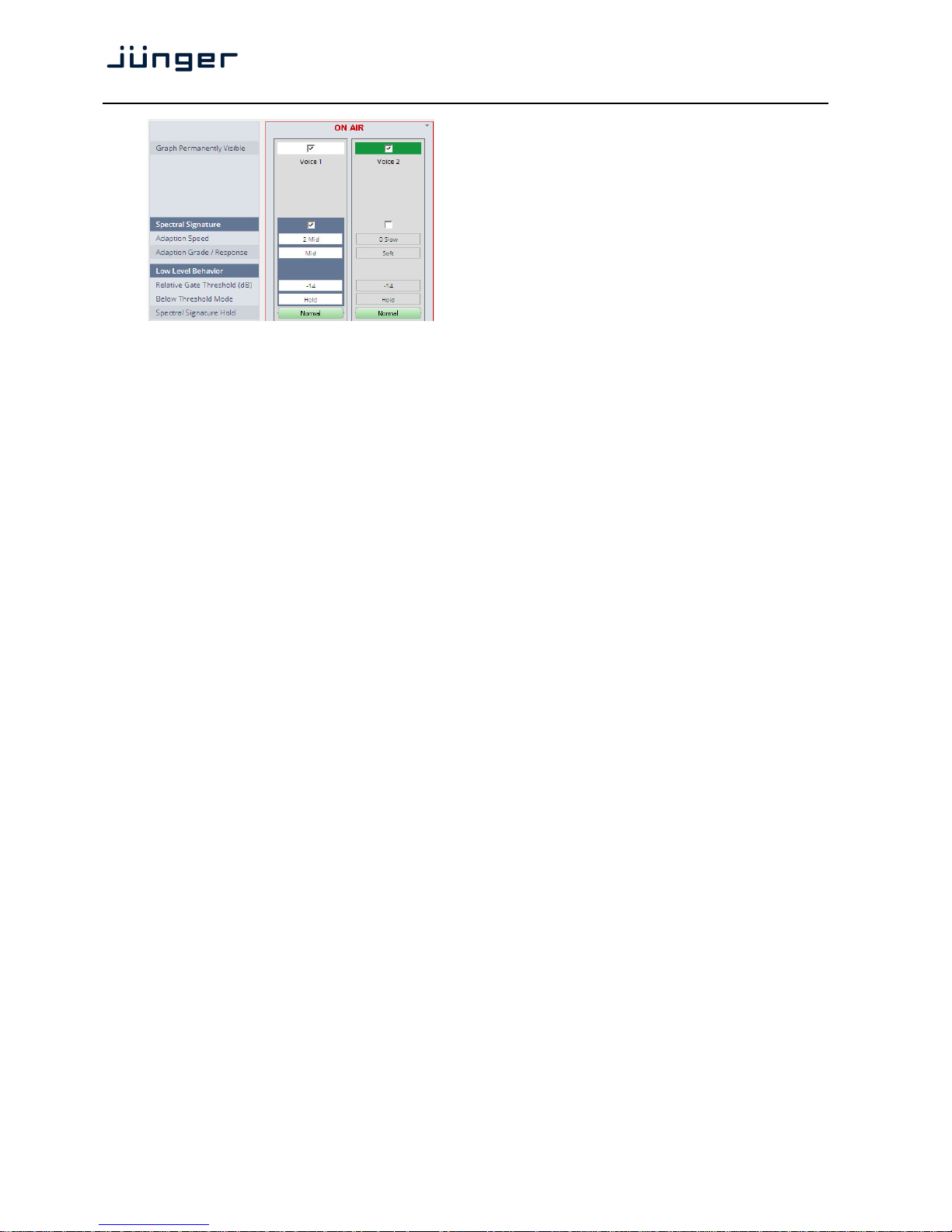
D*AP4 VAP
50
Graph Permanently [ON / OFF]
Visible The color code of the column
headers will change
depending on the voice
channel selected for display
(see upper display).
White color represents the
selected voice channel
(Voice 1 for example) while
the other channel shows dark
green.
Spectral Signature [ON / OFF]
Adaption Speed [0 / 2 Mid / 3 / 4 Fast]
This parameter affects the time taken for the bands to reach their target
values. Fast settings even out differences between sources, but can
lead to audible transitions. They are well suited for single channel
signals, for example to even out sound differences due to movement in
front of a microphone. Slower settings remain unobtrusive, but cannot
bring down differences very quickly. They are suitable for mixed content
or buses with varying content. The overall spectrum remains well
balanced without drastic sonic changes.
Adaption Grade / [Soft / Mid / Hard]
Response In order to achieve a stable and natural behavior, the intensity of the
gain change needs to process according to a response curve. This
curve is defined by a ratio. A high ratio means that a difference of 5dB
results in a gain change of almost the same amount. A low ratio means
that the actual gain applied is lower. A ratio of 2:1 would bring the
amplification up to 2.5dB in this example. The max gain value is applied
after the ratio calculation. As these ratios are not static, they have been
combined into three preset responses. The average ratio increases from
'soft' to 'hard'.
Low Level Behavior
Relative Gate [-10 …. -14 … -20 / OFF]
Threshold (dB) To prevent a band from amplifying noise (especially hum), a relative
gate can be set. If the energy within one band is lower than this gate, no
amplification will take place. This is especially useful, when mixed
content with highly varying frequency response is processed (for
example a radio station output with alternating presenter voice and
music).
Below Threshold Mode [Release / Hold]
In continuous operation the 'Below Threshold Mode' should remain in
'release'. In this case the dynamic gain slowly returns to its neutral state
in case of signal absence. In this mode a returning signal would start a
new processing period with its lead in attack time. This can be
undesired, especially in production applications where transport
operations introduce unnatural gaps. In those cases setting the 'Below
Threshold Mode' to 'hold' will pause the dynamic processing at the last
value until the signal returns. Returning signals are treated just like
continuous signals. This function has some similarities to the 'Freeze
Level' but works with a different designation as it is meant to keep
processing fluent over signal loss.
Page 55
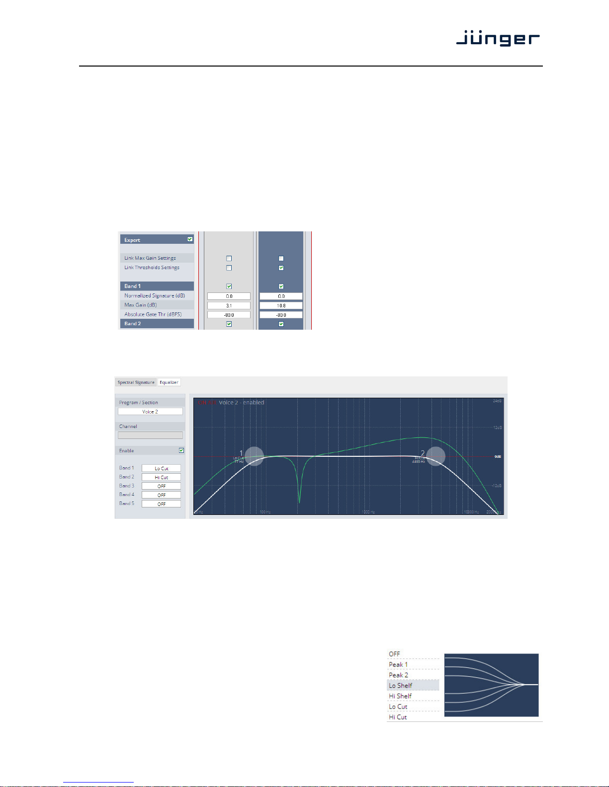
D*AP4 VAP
51
Spectral Signature Hold <Normal> / <Hold>
Hold freezes the dynamic adaption and preserves the current frequency
response curve, for as long as the function is activated. This can be
useful for example to prevent adaption to an inserted audio signal
(intermission, advertising…).
Expert [ON / OFF]
All parameters within the Expert section are duplicated in the Signature
and Spectrum graphs. They can be used to enter numerical values
directly. Changes are reflected in the graphs and likewise in reverse.
Link Max Gain Settings [ON / OFF]
Link Threshold Settings [ON / OFF]
Band 1 [ON / OFF]
Normalized [-40.0 … 0 … 40.0]
Signature level
Max Gain [0.0 … 12.0
Absolute Gate [-84.0 … 0.0]
Threshold
Band 2 … 16 similar parameters as Band 1
Setup GUI – AUDIO PROCESSOR – Filter – Equalizer
The graphical EQ offers 5 bands. The characteristic of each band can be setup either left hand side of
the graph or alternatively for each band further below.
Program / Section ["Voice 1" / "Voice 2" / Preset] or ["Voice 1" / Preset]
Selects the source for which the curve will be displayed.
This selection depends on the Voice Channel Mode
(see SYSTEM > Setup) and whether or not the channels are linked for
stereo operation.
Channel Applicable only if SYSTEM > Setup > Voice Channel Mode = Stereo
to select which channel must actually be displayed.
Enable [ON / OFF]
Same function as <Equalizer>
further below
Band 1 … 5 filter characteristic will be
selected by this pop up:
Page 56
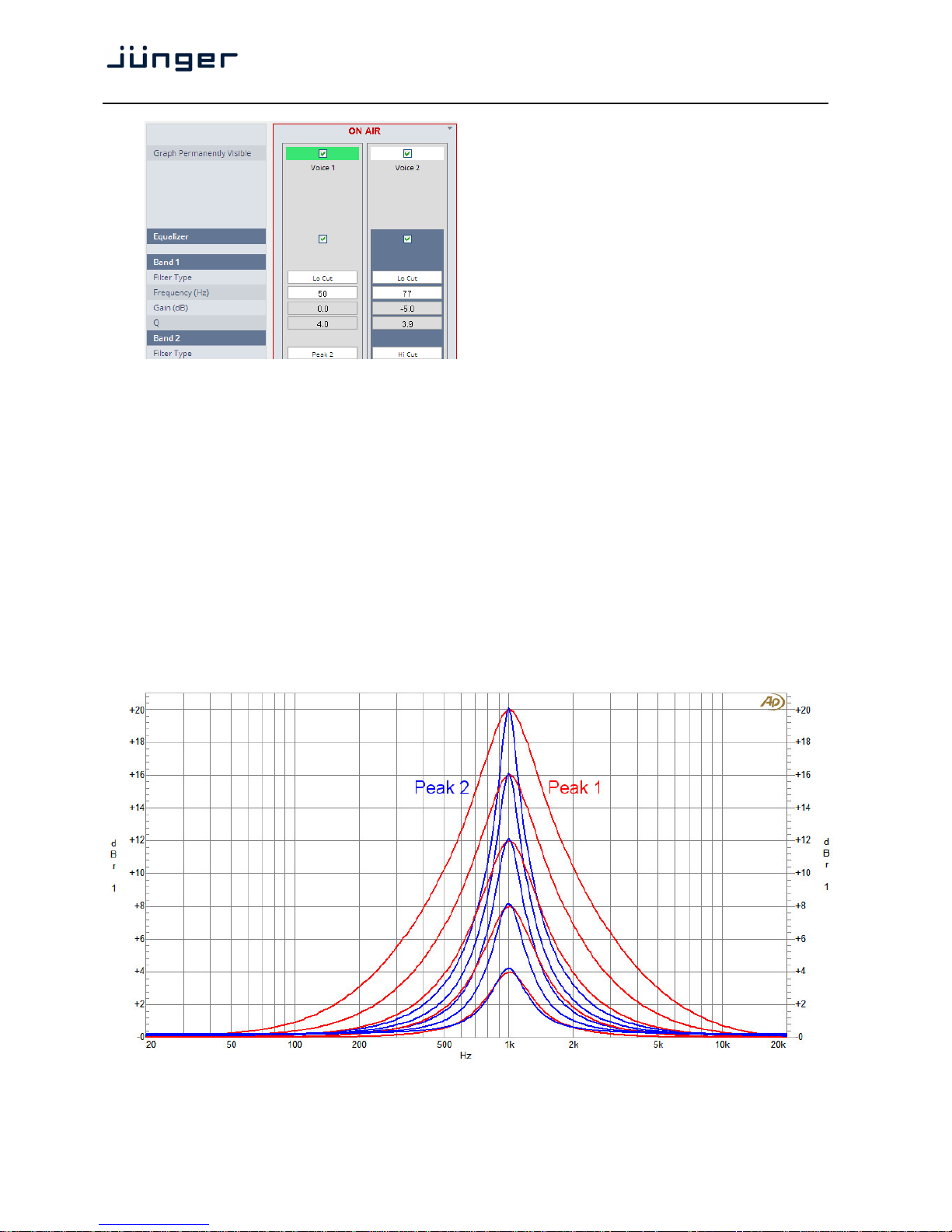
D*AP4 VAP
52
Graph The color code of the column
Permanently headers will change depending
Visible on the selected voice channel.
White color represents the actual
selected channel (Voice 2 for
example) while the other channel
shows light green.
Equalizer [ON / OFF]
Band 1
Filter Type will be selected by the pop up
Above.
Frequency (Hz) [20 … 20000]
Gain (dB) [-20.0 … 20.0]
Q [0.4 … 10.0]
Band 2 … 5 same parameter set as
Band 1.
Important Note! For numeric input double click into the parameter field. You must use the period as a
decimal separator. For graphical input use the left mouse button and drag it horizontally to change frequency
and vertical to change gain while the mouse wheel will change the Q value.
The EQs offer two different peak modes:
Peak 1: The bell curves of the Peak 1 filter features constant quality (Q) over gain.
Q is defined at -3dB below peak. It does not change when altering gain.
Peak2: The bell curves of the Peak 2 filter also features constant quality (Q) over gain.
But Q is defined at 50 % of gain. Subjectively the bell curve becomes sharper when
increasing gain, but this is only true for the lower 6-8dB of gain.
Page 57
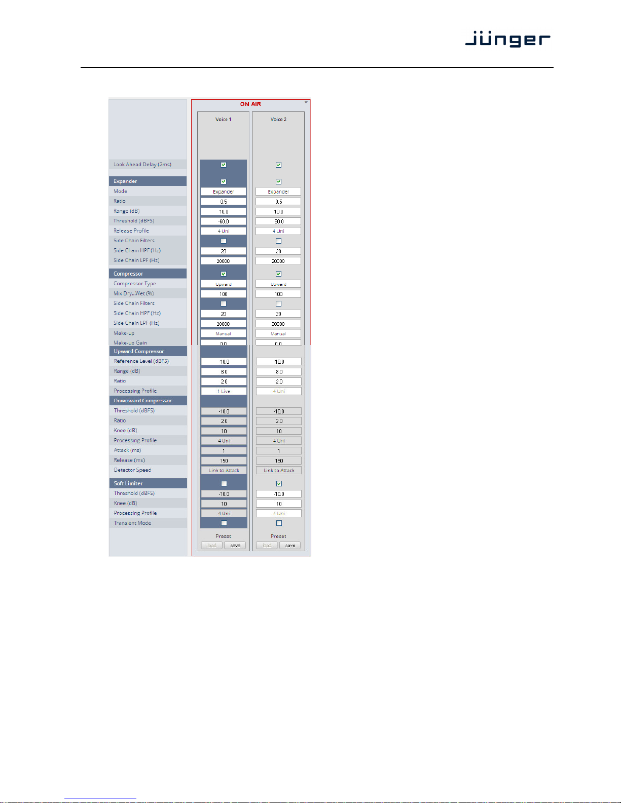
D*AP4 VAP
53
Setup GUI – AUDIO PROCESSOR – Dynamics
Look Ahead Delay [ON / OFF]
(2ms)
Expander [ON / OFF]
Mode [Expander / Gate]
Ratio [0.0 … 0.9]
Range (dB) [0.0 … 40.0]
Threshold (dB) [-80.0 … -10.0]
Release Profile [0 / 1 Live / 2 Speech /
3 Pop / 4 Uni / 5 / 6 Classic
/ 7 / 8 / 9]
Side Chain Filters [ON / OFF]
Side Chain HPF (Hz) [1 … 5000]
Side Chain LPF (Hz) [1000 … 20000]
Compressor [ON / OFF]
Compressor Type [Upward / Downward]
Mix Dry Wet (%) [0 … 100]
Side Chain Filters [ON / OFF]
Side Chain HPF (Hz) [1 … 5000]
Side Chain LPF (Hz) [1000 … 20000]
Make-up [Manual / Auto]
Make-up Gain [-40.0 … 40.0]
Upward Compressor
Reference Level [-60.0 … 0.0]
(dBFS)
Range (+/- dB) [0.0 … 20.0]
Ratio [1.1 … 8.0]
Processing Profile [0 / 1 Live / 2 Speech / 3
Pop / 4 Uni
5 / 6 Classic / 7 / 8 / 9]
Downward Compressor
Threshold (dBFS) [-60.0 … 0.0]
Ratio [1.1 … 8.0]
Knee (dB) [0 … 20]
Processing Profile [0 / 1 Live / 2 Speech / 3 Pop / 4 Uni / 5 / 6 Classic / 7 / 8 / 9 /
Manual]
Attack (ms) [1 … 100]
Release (ms) [10 … 1000]
Detector Speed [Peak / RMS / Link to Attack]
Soft Limiter [ON / OFF]
Threshold (dBFS) [-60.0 … 0.0]
Knee (dB) [0 … 20]
Processing Profile [0 / 1 Live / 2 Speech / 3 Pop / 4 Uni / 5 / 6 Classic / 7 / 8 / 9]
Transient Mode [ON / OFF]
Page 58

D*AP4 VAP
54
The dynamics section includes some technical features that are explained below:
Look Ahead Delay Traditionally, all Junger Audio dynamics feature a look ahead delay
(LAD) of 2 milliseconds. This allows the system to process fast
transients without missing even the steepest peaks. As the live audio
signal must be delayed for two milliseconds, this lag needs to be
considered when measuring overall latency. The LAD can be disabled,
if the advantage of the resulting lower latency prevails. Please keep in
mind that disabling LAD in one channel causes an offset between both
channels. This can be compensated for by the delay compensation
parameter in the Audio Processor Setup, but then again the latency
advantage disappears.
Side Chain Filters Some of the processing modules (De-Esser, Compressor,
Expander/Gate) feature Side Chain Filters to shape the audio signal
that feeds their detection system. It consists of independent high and
low pass filters with tunable cutoff frequencies. Those filters are not
audible within the actual signal chain. Its purpose is to make the
detection more or less sensitive to certain frequency ranges. As an
example to understand the benefits, with live speech the amount of
pop noise coming from the microphone varies highly. As it is not
advisable to generally reduce the amount of bass to preserve the
voice character, it is necessary to at least keep the bass thumps
from forcing the Compressor into heavy gain reduction. By reducing
the bass in the Compressor side chain, one can keep it from
overreacting (it does not 'know' of the thump, thus is not reacting to
it) while preserving the original frequency response.
Page 59

D*AP4 VAP
55
Expander
Mode The Expander can be switched to either working as an Expander or a
Gate. Both modes differ in two parameters:
Mode=Gate Fixed reduction ratio of infinite to one. All signals below threshold are
muted. No range available. Hard knee response at threshold.
Mode=Expander Selectable reduction ratio of 0:1 up to 0.9:1 with a selectable
maximum reduction of down to -40dB. Soft knee response with a
transition range of 6dB above and below threshold
Ratio Expansion ratio from 0:1 (heavy
reduction) up to 0.9:1 (slight reduction). A
ratio of 0.5:1 means that an input level of
1dB below threshold will result in an
output level of 2dB below threshold. In
the same way an input level of 4dB below
threshold results in an output level of 8dB
below threshold and so on.
Range Maximum reduction range. Its value
determines the maximum reduction of the
input signal. This parameter is
sometimes called 'floor', but differs in
terminology. A floor level is defined as an
absolute value in dBFS, no matter where
the threshold is set. Range defines the
relative range of reduction in dB below
threshold and is thus independent from
absolute values.
Threshold Signals below threshold are processed,
signals above pass unaffected. Please be
aware that this is only true in Gate mode,
as the Expander mode features soft knee
characteristics.
Release profile The release profile controls the timing of the closing of the
Gate/Expander. Release profile 0 is a very fast profile and even short
gaps or signal intermissions lead to gain reduction. At the other end of
the scale, 9 is a very slow profile with a relaxed handling of gaps and
low level periods. All profiles feature the same super fast opening
when the signal returns above threshold.
Compressor (general parameters)
Compressor Type The compressor features two different approaches to dynamic
processing. In Upward mode all signals below reference level are
amplified according to the ratio and range settings, all signals above
reference level are reduced in the same way. This is the 'classic'
approach of earlier Junger Audio compressor designs. The Downward
mode is the more common way of dynamic range compression. Here
all signals above threshold are reduced according to the ratio while all
signals below threshold remain untouched.
Mix Dry...Wet In most settings, the full signal is fed to a compressor to achieve a
certain level of gain reduction. Sometimes it is useful to add a portion
of the original, uncompressed signal to the output to restore some
micro dynamics. This technique is called 'parallel compression'. The
ratio of dry (unprocessed) and wet (compressed) signal can be dialed
in with this Mix parameter.
output
gate
e
x
p
a
n
d
e
r
input
soft knee
threshold
range
Jünger Audio – Expander/Gate
Page 60
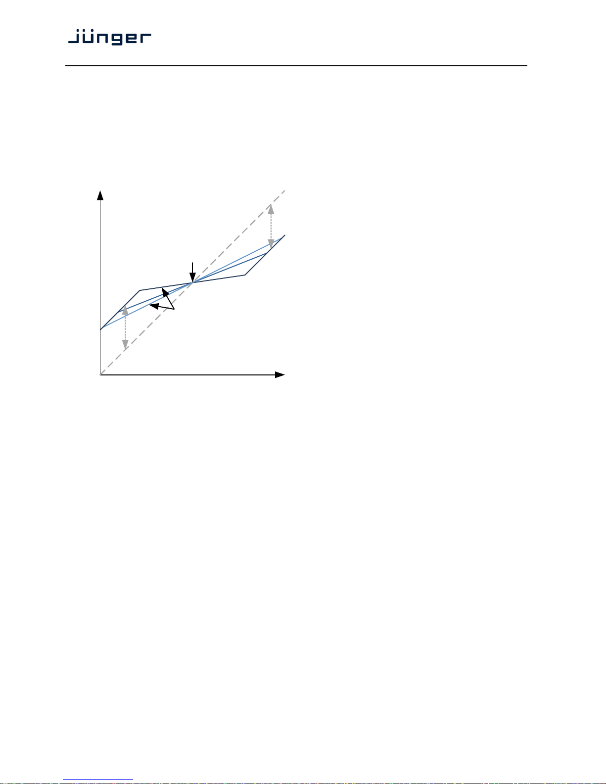
D*AP4 VAP
56
Make-Up To set up the desired output level of the compressor, Make-Up Gain
(or attenuation) needs to be applied. This is a simple and static output
level adjustment without any dynamic content. In Auto mode the
amount of Make-up Gain is automatically determined depending on
the threshold and ratio settings. When set to manual, its value can be
set in steps of 0.1dB.
Upward Compressor
Reference Not to be confused with threshold, this
Level parameter defines the turning point of the
response curve from upward to
downward compression (see picture).
When set to 0dBFS, the signal is
amplified according to the ratio and range
settings.
Range This defines the range over which
dynamic compression is applied as
defined by the ratio setting. Signals
outside this range are still reduced or
amplified but not altered in their dynamic
structure.
Ratio Determines the amount of gain reduction
by a selectable ratio. Although the same
in mathematical terms, understanding is
easier when differentiating between
upward and downward compression:
Downward An example ratio of 2:1 means that an input level of 4dB above
compression ratio threshold will result in an output level of 2dB above threshold. In the
same way an input level of 8dB above threshold results in an output
level of 4dB above threshold and so on.
Upward compression ratio A ratio of 2:1 means that an input level of 4dB below reference level
will result in an output level of 2dB below reference level. In the same
way an input level of 8dB below reference level results in an output
level of 4dB below reference level and so on.
Processing Profile The timing characteristics of the compressor are generated adaptively
according to the incoming signal structure. The overall timing can be
set up from fast and responsive settings (lower numbers) to relaxed
settings (higher numbers) without detailed access to the actual micro
timings. The names behind some of the numbers may help to easily
find adequate values to your content. For profile "Manual" one may set
"Attack", "Release" and "Detection Speed".
Downward Compressor
Threshold Signals above threshold are processed, signals below pass
unaffected. Please be aware that this is only true when Knee
is set to '0'.
Ratio Please see ratio description in Upward Compressor section.
Knee The Knee parameter allows the user to decide whether the transition
from linear to processed happens immediately at threshold (so called
hard knee) or if a transition range (soft knee) is applied in which the
ratio is steadily raised from 1:1 at the lower knee end up to the defined
ratio at the upper range (see picture).
output
input
reference
level
compression ratios
range
range
Jünger Audio – Upward Compressor
Page 61
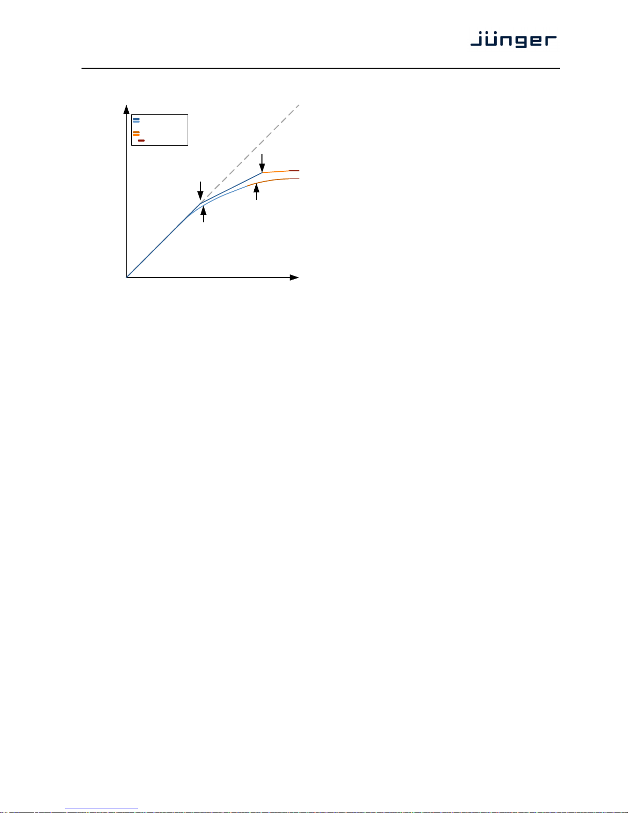
D*AP4 VAP
57
Processing The timing characteristics of the
Profile compressor are generated adaptively
according to the incoming signal
structure. The overall timing can be set
up from fast and responsive settings
(lower numbers) to relaxed settings
(higher numbers) without detailed access
to the actual micro timings. The names
behind some of the numbers may help to
easily find adequate values to your
content. Alternatively the timings of
Attack and Release (return to neutral)
can be set up manually. In this case they
are not adaptive to the input.
Attack Settling time after exceeding threshold.
Defined as the time period to achieve
63% of full reduction according to signal
level.
Release Time constant for the process to return to zero after signal fallback
below threshold. The system returns with 8.6dB per time constant.
Detector Speed The internal level detector of the compressor is configurable with three
settings [Peak / RMS / Link To Attack]:
Peak the system detects every single signal peak and reacts accordingly
with fast and appropriate gain reduction.
RMS Instead of 'riding on peaks' the detector analyses the energy of the
signal and reacts with a more moderate and more 'musical' reduction.
Link To Attack The length of analysis is coupled to the setting of Attack. With a slower
attack the RMS analysis is based on a longer portion of the signal. On
the other hand a fast Attack setting brings the analysis very close to
the Peak behavior.
Soft Limiter When working in a non-loudness based audio environment, it became
common practice to use the output limiter (typically set to -9dBFS) as
a creative tool for compression. In a modern, loudness based studio
this option got lost. As a substitute, the new Soft Limiter brings back
the option of using a dedicated sample peak limiter with soft knee
characteristics for the microphone processing chain.
Threshold Signals above threshold are processed, signals below pass
unaffected. Please be aware that this is only true when Knee
is set to '0'.
Knee The Knee parameter allows the user to decide whether the transition
from linear to processed happens immediately at threshold (so called
hard knee) or if a transition range (soft knee) is applied in which the
ratio is steadily raised from 1:1 at the lower knee end up to the defined
ratio at the upper range (see picture).
Processing Profile The timing characteristics of the Soft Limiter are generated adaptively
according to the incoming signal structure. The overall timing can be
set up from fast and responsive settings (lower numbers) to relaxed
settings (higher numbers) without detailed access to the actual micro
release timings. The names behind some of the numbers may help to
easily find adequate values to your content.
Transient Mode With the transient mode enabled the response curve of the Soft
Limiter is reduced down to infinity to one. This is useful in settings
where a wide knee may not have run out fully before full scale is
reached.
output
input
soft knee
compressor
threshold
soft limiter
threshold
soft knee
compressor
soft limiter
transient mode
Jünger Audio – Downward Compressor and
Soft Limiter
Page 62
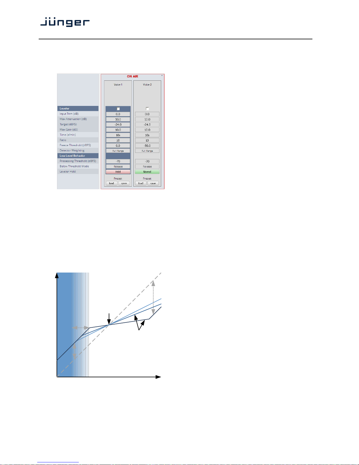
D*AP4 VAP
58
Setup GUI – AUDIO PROCESSOR – Leveler
The new Leveler is optimized for single channels. Its main purpose is to balance an already processed
signal to a certain target level.
Leveler [ON / OFF]
Input Trim (dB) [-80.0 … 0.0 …. 20.0]
Simple input level trim to
prevent the Leveler from
reducing static offset. Hint: To
use the Input Trim without the
Leveler, simply reduce its Max
Attenuation and Max Gain
down to 0.
Max Attenuation [0.0 … 10.0 … 40.0]
(dB) Defines the maximum
attenuation or damping of the
Leveler process for signals
that exceed the target level.
Target (dBFS) [-50.0 … -24.0 … 0.0]
This is the balance point of the Leveler. Signals that exceed the
target are reduced, signals below target are amplified to bring the
overall level to this center of gravity.
Max Gain (dB) [0.0 … 10.0 … 40.0]
Defines the maximum amplification of the Leveler process for signals
that are below the target level.
Time (s/min) [1s … 30s … 2min]
This defines the timing for the
Leveler to reach target. Of
course this is not an absolute
value as it depends on the
input level, signal structure,
ratio and necessary amount of
gain change.
Ratio [1 … 10 … 40]
As opposed to a classic
compressor, the Leveler ratio
is normally fixed to infinity to
one. With this Leveler you can
bring down the ratio to a much
lower value to achieve a more
relaxed compensation instead
of heavy steering towards
target. Setting it to 1:1
disables the leveling process.
Freeze Threshold [-60.0 … -50.0 … 0.0]
(dBFS)
output
input
target
leveler ratios
max gain
max
attenuation
freeze range
full freeze
Jünger Audio – Leveler
Page 63

D*AP4 VAP
59
Detector Weighting [Full Range / Proximity / Loudness]
The Leveler features a Side Chain Filter with special characteristics to
adapt the leveling process to three major applications.
Full Range The Side Chain is not filtered and the Leveler is running on full
bandwidth detection.
Proximity The Side Chain uses a low shelf filter to compensate for microphone
proximity effects.
Loudness
In modern broadcast production environments the final product is
played out in accordance with current loudness standards. Those
standards and recommended practices always refer to the output
signal and do not consider the condition of the source channels. This
is correct, but never the less, it can be very useful to consider
loudness for these single channels. With this loudness filtering you can
bring the output to a consistent level, based on modern loudness
recommendations. The output will integrate seamlessly into your
loudness normalized product. In many situations, no additional
loudness correction is necessary. This approach is compatible with all
international loudness recommendations.
Technical remark: K-Filtering is used as described in
ITU-R BS 1770-3.
Low Level Behavior
Processing Threshold [-80 … -70 … -20]
Below Threshold Mode [Release / Hold]
In continuous operation the 'Below Threshold Mode' should remain in
'Release'. In this case the dynamic gain slowly returns to its neutral
state in case of signal absence. In this mode a returning signal would
start a new processing period with its lead in attack time. This can be
undesired. In those cases setting the 'Below Threshold Mode' to 'hold'
will pause the dynamic processing at the last value until the signal
returns. Returning signals are treated just like continuous signals. This
function has some similarities to the 'Freeze Level' but works with a
different designation as it is meant to keep processing fluent over
signal loss.
Leveler Hold [Normal / Hold]
Leveler Hold freezes the levelers dynamic gain and preserve its
current state, for as long as the hold function is activated. This can be
useful for example to prevent loud sounds like sneezing or coughing
from causing leveler action.
Page 64
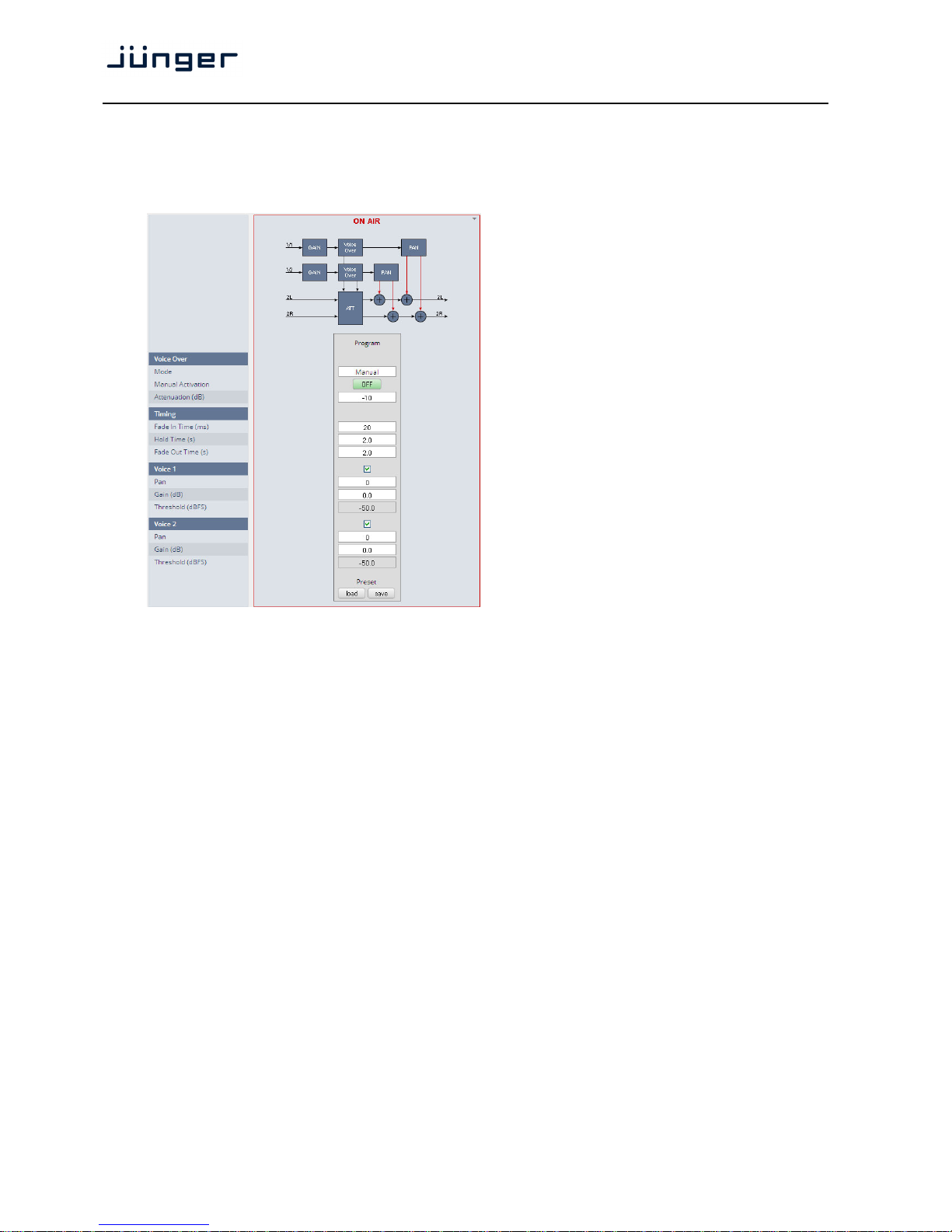
D*AP4 VAP
60
Setup GUI – AUDIO PROCESSOR – Voice Over
The voice over section allows for manual (mixing) / automatic (ducking) of a voice channel over the
program feed. The dynamic schematic in the top of the pane shows the signal flow.
(SYSTEM > Setup > Voice Channel Mode = Stereo).
Voice Over
Mode [OFF / Always ON /
AUTO / Manual]
Manual Activation [ON / OFF]
Attenuation (dB) [-40 … 0]
Timing
Fade In Time (ms) [10 … 20 … 1000]
Hold time (s) [0.0 … 2.0 … 10.0]
Fade Out Time (s) [0.0 … 2.0 … 10.0]
Voice 1 [ON / OFF]
Pan [-50 … 0 … 50]
Gain (dB) [-80.0 … 0.0 … 20.0]
Threshold (dBFS) [-60.0 … -50.0 … 0.0]
Voice 2 [ON / OFF]
Pan [-50 … 0 … 50]
Gain (dB) [-80.0 … 0.0 … 20.0]
Threshold (dBFS) [-60.0 … -50.0 … 0.0]
The Pan values represent the direction of the voice over signal in the program output from
left [-50] over mid [0] to right [50].
Page 65
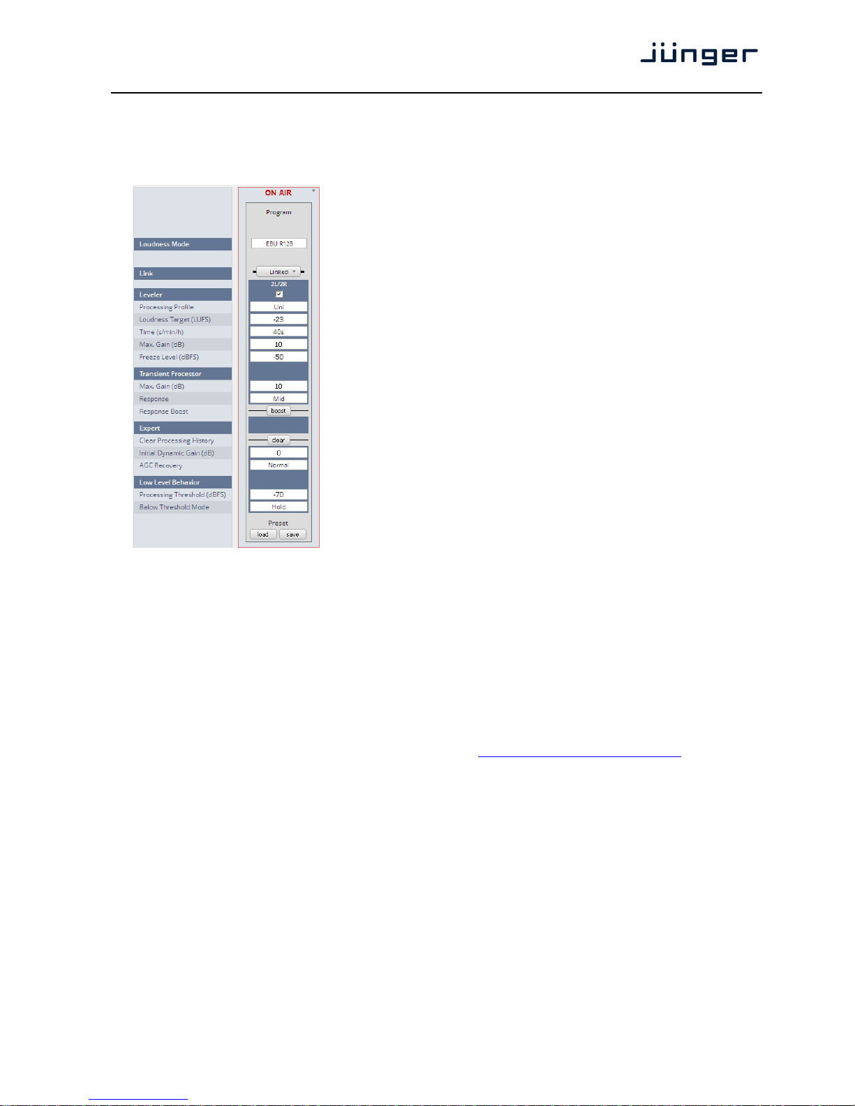
D*AP4 VAP
61
Setup GUI – AUDIO PROCESSOR – Level Magic
This function block is used for loudness control of the program path. It can be used to control an
independent program signal or a program signal including voice over (see Overview diagram).
Loudness Mode [Level / ITU BS.1770-1 / -2 / -3
EBU R128 / ARIB TR-832 /
ATSC A/85 (2011) /
ATSC A/85 (2013) /
Free TV OP-59 / Portaria 354)
Link [Linked, Unlinked]
The program path may be
unlinked for dual mono
operation.
Leveler [ON / OFF]
Processing Profile [Live / Speech / Pop / Uni /
Classic]
Loudness Target (LUFS) [-50 … 0]
Time (s/m/h) [10, 20, 40 / 1, 2, 5, 10, 20 40 /
1, 2]
Max. Gain (dB) [0 … 10 … 40]
Freeze Level (dBFS) [-60 … -50 … -20]
Transient Processor
Max. Gain (dB) [0 … 10 … 15]
Response [Soft / Mid / Hard]
Expert [ON / OFF]
Clear Processing History <clear>
Initial Dynamic Gain (dB) [-40 … 0 … 15]
AGC Recovery [Normal / Fast]
Low Level Behavior
Processing Threshold (dBFS) [-80 … -70 … -20]
Below Threshold Mode [Release / Hold]
For details regarding LevelMagic parameters see the bulletin: "Junger_LevelMagic-LevelerDynamics_Parameters_161128.pdf" on the Junger web site
http://junger-audio.com/downloads.
Page 66
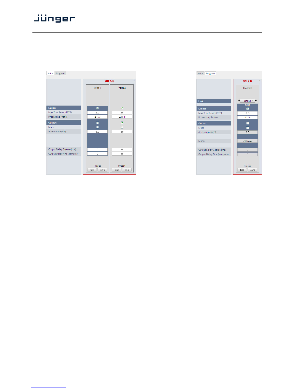
D*AP4 VAP
62
Setup GUI – AUDIO PROCESSOR – Output
The Output block allows you to use a True Peak limiter, Mute and Attenuate the output signals from the
DSP, do a mono conversion for stereo channels and add delay. This may be set independently for both the
voice and the program channel.
Link [Unlinked / Linked]
For voice channel only available if it is in stereo mode.
Limiter [ON / OFF]
Max True Peak (dBTP) [-20.0 … 0.0]
Processing Profile [0 / 1 Live / 2 Speech / 3 Pop / 4 Uni
5 / 6 Classic / 7 / 8 / 9]
Output [ON / OFF]
Mute [ON / OFF]
Attenuation (dB) [-80.0 … 0.0]
Mono [L/R Stereo / L+R Mono / L/L Mono / R/R Mono]
Output Delay Coarse (ms) [0 … 2000]
Output Delay Fine (samples) [0 … 2000]
If the voice channel mode is set to stereo (see SYSTEM > Setup > Voice Channel Mode = Stereo)
a mono circuit will be available for the voice channel as well.
Page 67
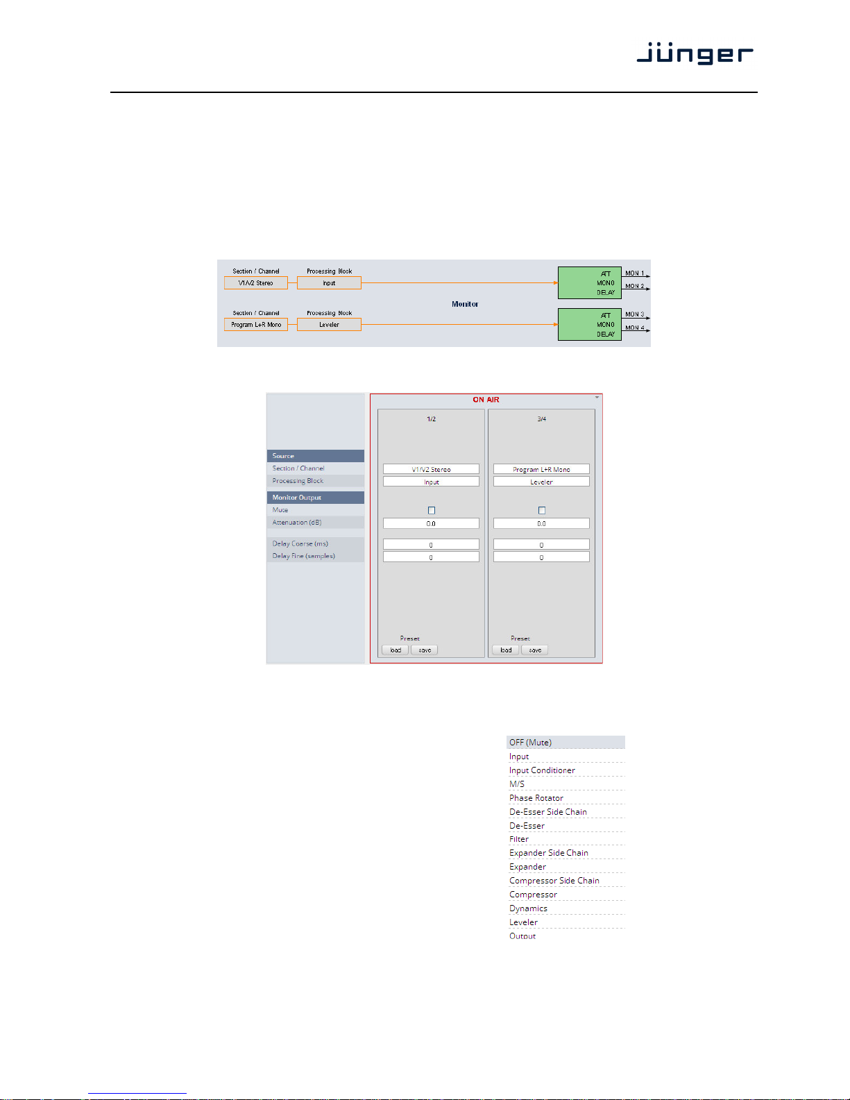
D*AP4 VAP
63
Setup GUI – AUDIO PROCESSOR – Monitor
As seen on the AUDIO PROCESSOR > Overview page the D*AP4 VAP provides two monitor facilities
which may be connected to the function blocks of the audio processor (DSP).
For the example below (see SYSTEM > Setup) the VAP is in Voice Channel Mode = "Stereo".
The first monitor is connected to the Input section of the voice channels in Stereo [V1/V2 Stereo]
while the second monitor is connected to the Leveler output of the Program path in L+R Mono
[Program L+R Mono] (see AUDIO PROCESSOR > Overview):
The settings must be done on the Monitor pane:
Source
Section / Channel [V1/V2 Stereo / V1+V2 Mono / Program Stereo / Program L/L Mono
Program R/R Mono / Program L+R Mono]
Processing Block Select here which processing
block should be monitored
Monitor Output
Mute [ON / OFF]
Attenuation (dB) [-80.0 … 0.0]
Delay Coarse (ms) [0 … 2000]
Delay Fine [0 … 2000]
(samples)
Page 68
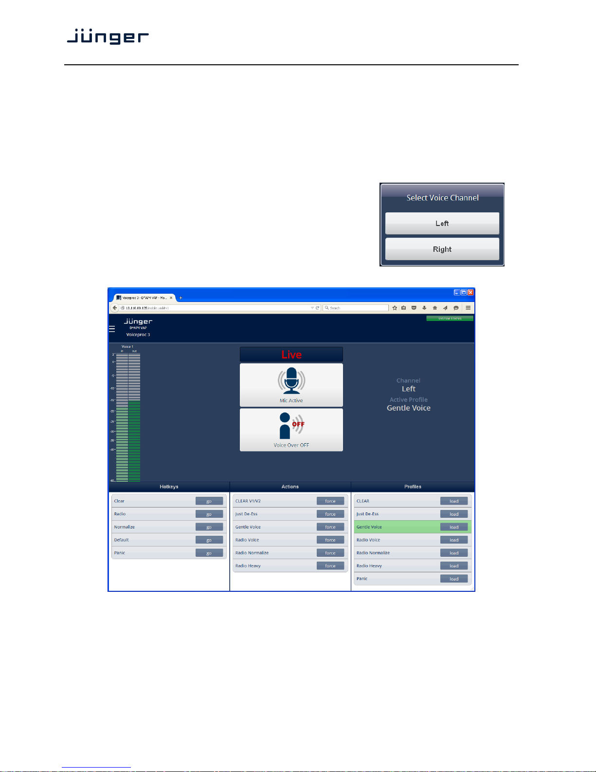
D*AP4 VAP
64
Setup GUI – AUDIO PROCESSOR – On Air / Mobile UI
The V'*AP provides an operator UI for live application that may be used on tablets or mobile phones
but may also be displayed on a PC's web browser. When you click on the <Mobile> soft button in the
upper right area of the GUI above the <Help> button, a new tab in your current browser will open up.
But you can also use the URL: "<IP-address>/mobile" to open the operator UI elsewhere
(in a browser of a different PC or a mobile phone or a tablet). For mobile devices it requires wireless
accessibility of the D*AP4 VAP via a WLAN.
If the device is setup for two independent voice channels
(see SYSTEM > Setup Voice Channel Mode = 2 x Mono)
you must select one of the two voice channels firstly.
In case of Voice Channel Mode = Stereo both channels will be
controlled via Voice 1 channel.
Keep in mind that you may assign meaningful names to the
voice channels (see SYSTEM > Setup > Section / Channel Labels).
For this explanation we named them "Left" and "Right".
The appearance of the mobile UI may be configured at SYSTEM > Remote Access > Mobile UI.
Page 69
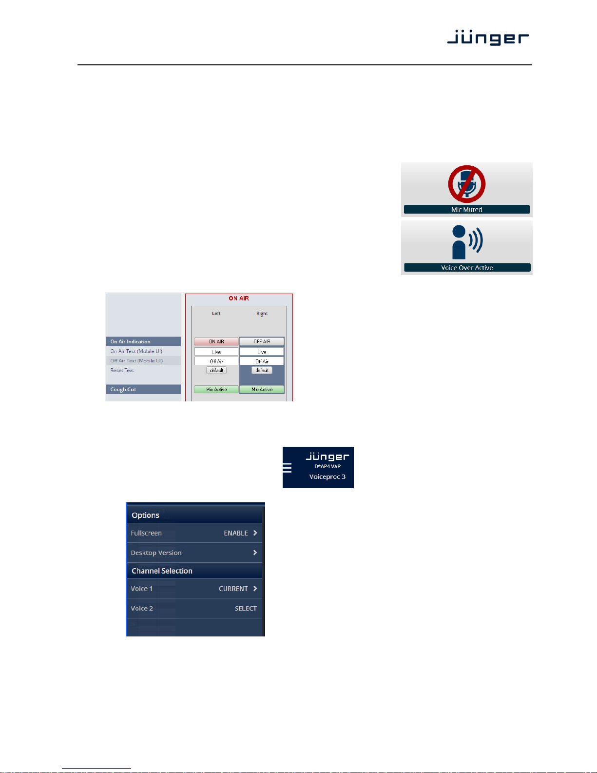
D*AP4 VAP
65
The content of this operating UI duplicates useful controls of the V*AP. You may activate Hotkeys
which are assigned to the X*AP RM
1
remote panel which in turn maybe setup for trigger actions
of the event manager (see EVENTS > Triggers > Remote Hotkeys)
for details).
But you may directly trigger Actions or Preset Events at the bottom of the screen as well.
The mobile UI will only display preset events which contain processing relevant parameters called
"Profiles". I.e. you can not reconfigure the VAP from here.
On a touch screen (or via left mouse button) you may simply press
the icons (if enabled via SYSTEM > Remote Access > Mobile UI)
in the middle of the screen to temporarily mute that channel
for a cough cut function or to turn voice over on / off.
The text at the top of the button(s) can be defined via the web GUI.
The system distinguishes between two possible texts.
On Air Indication [OFF AIR / ON AIR]
turns that mic channel permanently
on or off
On Air Text will be displayed if the mic is on air
(Mobile UI)
Off Air Text will be displayed if the mic is off air
(Mobile UI)
Reset Text will restore the default text for both
the on air and the off air display
Cough Cut temporary mic mute button.
It works in parallel to the mobile UI's
<Mic Active> button.
The option menu at the upper left hand
side offers some additional settings
from the mobile GUI:
You can set the browser to full screen or call the
setup GUI via <Desktop Version>.
Finally you may change the voice channel that is under
control from the mobile UI.
Page 70
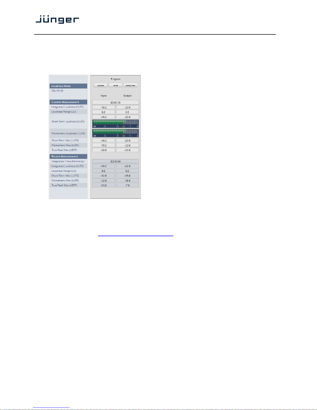
D*AP4 VAP
66
Setup GUI – MEASURMENT – Loudness
The D*AP4 VAP offers a sophisticated loudness measurement tool for the input and output of the
program path of the device. The three control buttons <pause>, <reset>, <reset max> may be used to
manually control the actual measurement.
Loudness Mode Defined at the Level
Magic setup pane.
Current Measurement [hh:mm:ss]
Integrated Loudness (LUFS)
Loudness Range (LU)
Short Term Loudness (LUFS)
Momentary Loudness (LUFS)
Short Term Max (LUFS)
Momentary Max (LUFS)
True Peak Max (dBTP)
Resent Measurement
Integrated Time (hh:mm:ss)
Integrated Loudness (LUFS)
Loudness Range (LU)
Short Term Max (LUFS)
Momentary Max (LUFS)
True Peak Max (dBTP)
For the terms and details of loudness measurement we would ask you to consult the respective
standards like EBU R128 issued by the EBU (EBU_tech3341, 3342, 3343, 3344). You will also find
explanations here: "Junger_LevelMagic-Leveler-Dynamics_Parameters_161128.pdf "
on the Junger web site
http://junger-audio.com/downloads.
Page 71
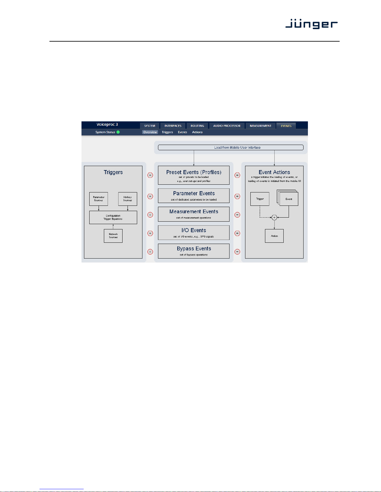
D*AP4 VAP
67
Setup GUI – EVENTS – Overview
The D*AP4 VAP offers a sophisticated event management system.
The event system performs Actions. These Actions are built from Events.
Actions may be triggered manually (via the X*AP RM
1
remote panel Hotkeys or from the operator UI),
semi-automatically (triggered by network commands or GPIs) and automatically (triggered by changes of
parameters and/or the internal status) or as a combination of all three.
The overview shows the building blocks of the action management of the D*AP4 VAP.
The examples further below are taken from the actual set of factory pre-set events based on a number
of useful presets:
A trigger is subdivided into a trigger type and a trigger source. E.g. a GPI is a trigger type while its
number (the physical input) represents the trigger source. Other trigger types have sources which must
be configured, like the names of X*AP Hotkeys or network triggers.
Hotkey Sources You may assign hotkeys of the X*AP remote and / or the
mobile UI to become a trigger source.
Network Sources Received via the EmBER+ protocol.
Parameter Sources Device parameters / status information grouped into
systems and Interfaces.
The triggers will finally be defined by a trigger equation that may be the logical combination of two
trigger sources.
The D*AP4 VAP knows five different event types:
Preset Events (Profiles) System / Interfaces / Routing / Audio Processor /
Voice / Program / Monitor
Parameter Events System / Audio Processor / Measurement
Measurement Events Pause / Continue / Reset / Reset Max / Start / Pause / Stop
I/O Events GPOs
Bypass Events Voice / Program
Page 72
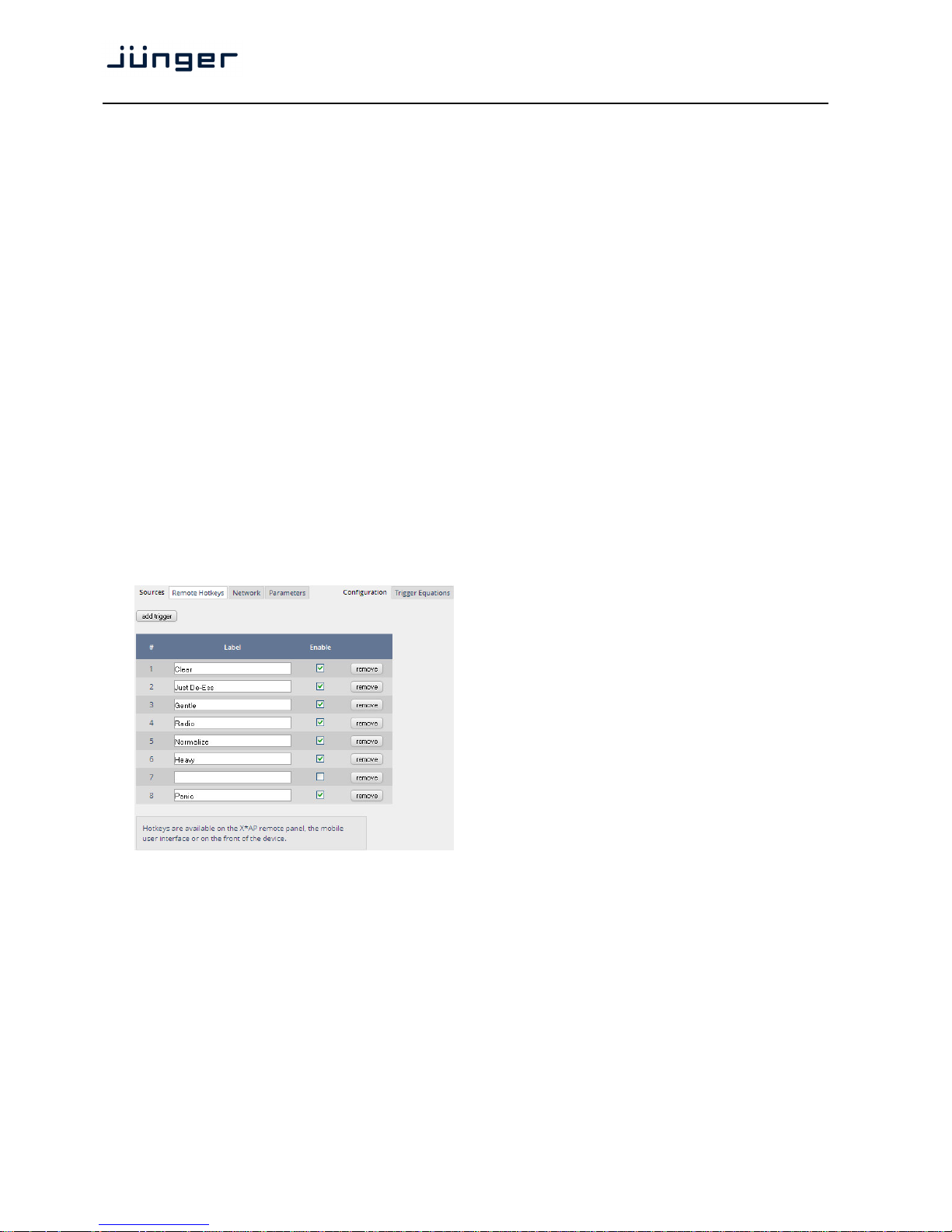
D*AP4 VAP
68
The D*AP4 VAP has two different action types:
Event Actions executes the predefined events
Bypass Actions executes pre-defined bypass scenarios, independent on
the bypass events
An action runs like a flip-book inside the D*AP4 VAP. This powerful technology spans from simply
recalling a certain parameter over narrator specific parameter combinations (household name: "Preset")
to the complete reconfiguration of the D*AP4 VAP including all signal routing, processing parameters
and so forth. It also allows you to create your own snap shots where you decide what is part of it and
what is not! But it also enables several fail over scenarios where the D*AP4 VAP will automatically
react to the system and/or parameter status.
The steps to set up the EVENTS system are as follows:
1.
Define - trigger sources
2. Configure - triggers by logical combination of pre defined trigger sources
3. Set up events - by selecting presets for function blocks
4. Create actions - what will happen - which trigger will launch which event? Or what will happen
in case of some one presses the <BYPASS> button at the X*AP RM
1
or is
engaging the <Force Trigger Active> check box or ignite an action from the
mobile UI.
Setup GUI – EVENTS – Triggers – Sources – Remote Hotkeys
Hotkeys are the 8 buttons of an X*AP RM1 remote panel. You may give them names and enable them
to become active on the X*AP RM
1
remote panels main operating menu:
<add trigger> You can add lines here.
# The number of the Hotkey on the
X*AP RM
1
remote panel, counting
from left to right.
Label Each Hotkey may have a label that
appears in the display of the
X*AP RM
1
remote panel above that
button.
Enable [ON / OFF]
If you turn it off the respective
Hotkey on the X*AP RM
1
remote
panel becomes inactive - no label is
displayed and the button
background light turns off.
<remove> will remove a line from the list. This
will automatically disable the
respective front panel button.
The number of hotkey triggers is not limited. You may also add virtual hotkeys which can be used by a
graphical UI for example that may have more than 8 compared to the X*AP RM
1
.
Page 73
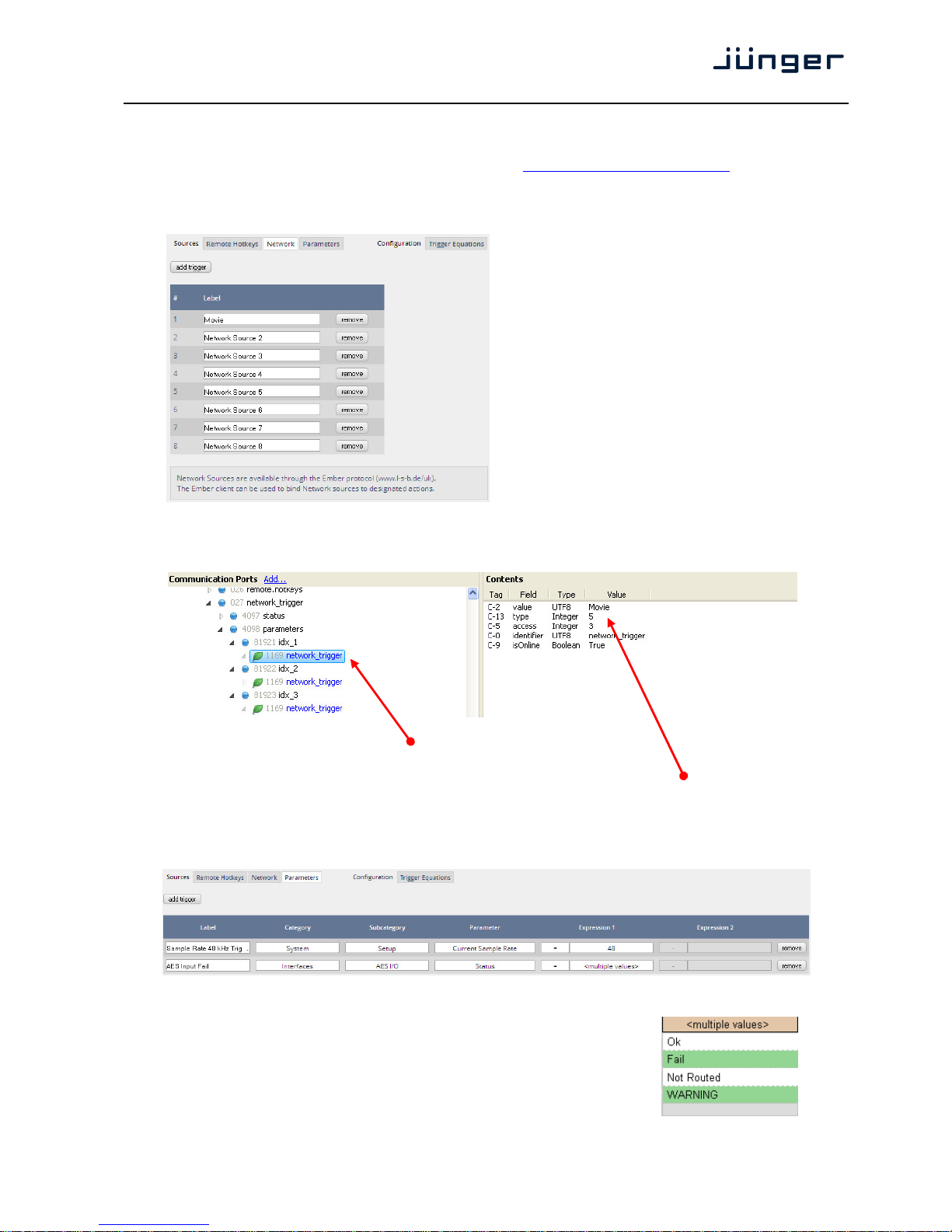
D*AP4 VAP
69
Setup GUI – EVENTS – Triggers – Sources – Network
Network triggers are based on the EmBER+ protocol. See
code.google.com/p/ember-plus/ for details.
The D*AP4 VAP receives such triggers over the TCP/IP network. The triggers are issued by a remote
device or a broadcast automation system. You may assign these triggers to virtual panels, physical buttons
or play list events of Ember+ enabled control instances.
# The number of the network trigger.
Label Label of that network trigger.
It appears on the Configuration
pane as well as in the EmBER+
tree of the setup interface of a
control instance.
<remove> will remove a line from the list.
Below is a screen shot of the EmBER viewer tool:
In the EmBER+ tree you go to:
"Device" > controller_dsp > network_trigger > parameters > e.g. "idx_1"
As a value you will receive the trigger name from the D*AP4
VAP. In this example it is the first trigger named: "Movie".
Setup GUI – EVENTS – Triggers – Sources – Parameters
Above is an example of parameter trigger sources. <multiple values> indicates that more than one
value of the parameter "Status" is bound to that trigger source:
If you click into the "Expression 1" field you see two
entries marked greenish, i.e. if one of these values is true,
"Expression 1" is true. You must uncheck both in order to select
a different setting afterwards.
Page 74
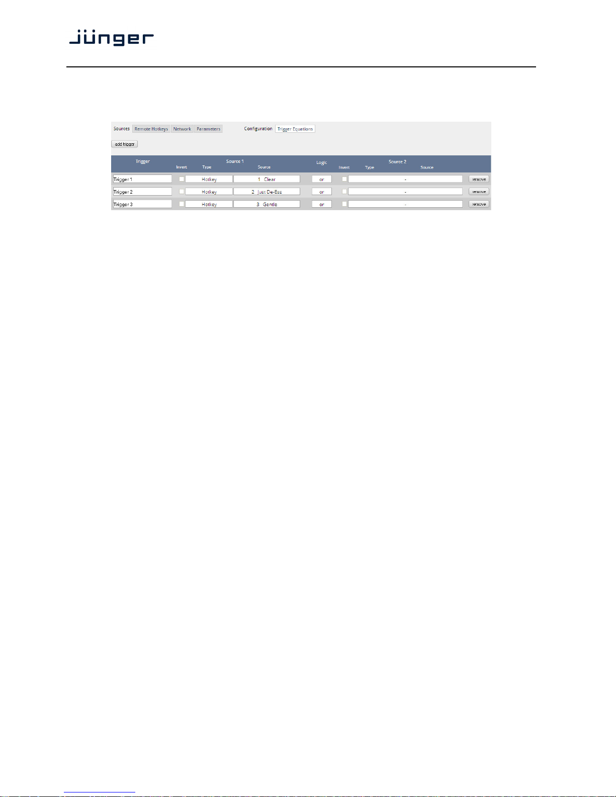
D*AP4 VAP
70
Setup GUI – EVENTS – Triggers – Configuration – Trigger Equation
To form a trigger you may logically combine two trigger sources:
Trigger Here you define a name for the trigger (Trigger 1).
Source 1 The first source of a logical combination of two trigger sources.
Invert [ON / OFF]
If the type of trigger allows an inverted operation it can be defined here.
Type [GPI / Hot Key, Network / Parameter / Event active / Trigger effective/
Bypass / Sync Lock]
Source [e.g. for GPIs it will be 1 … 8]
It acts like an index for the trigger type (In case of GPI it is the physical
GPI number or in case of X*AP Hotkeys the key number (1 of 8)
Logic Kind of logical operation [and, or, xor].
Source 2 Second source for the logical combination of two trigger sources. If only
one source exists, you may leave it unassigned [-].
Page 75
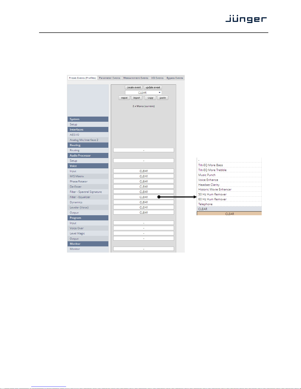
D*AP4 VAP
71
Setup GUI – EVENTS – Events – Preset Events (Profiles)
A preset event is a group of presets you may load on one occasion to the On Air parameters of function
blocks. When executing such an event you may for example change the De-Esser, compressor and EQ
settings, by simply assigning the individual preset of your choice to the processing block or the system,
to an interface, to the routing, to the program path or even to the monitor output:
The example shows that the factory default profile CLEAR is selected.
It will load the presets CLEAR for each function block of the voice channel.
I.e. each function block has a preset with the name CLEAR. Don't be confused by the same name of
the presets!
This is the tool to reconfigure the D*AP4 VAP completely, partially or to change a few audio parameters
marginally. At the top of the page you see the button <create event>. It may save all actual parameters
in presets of the respective function block and assigns it the same name as the event itself.
Pull down list of all factory
default presets of the FilterEqualizer section where
CLEAR is one of it
Page 76
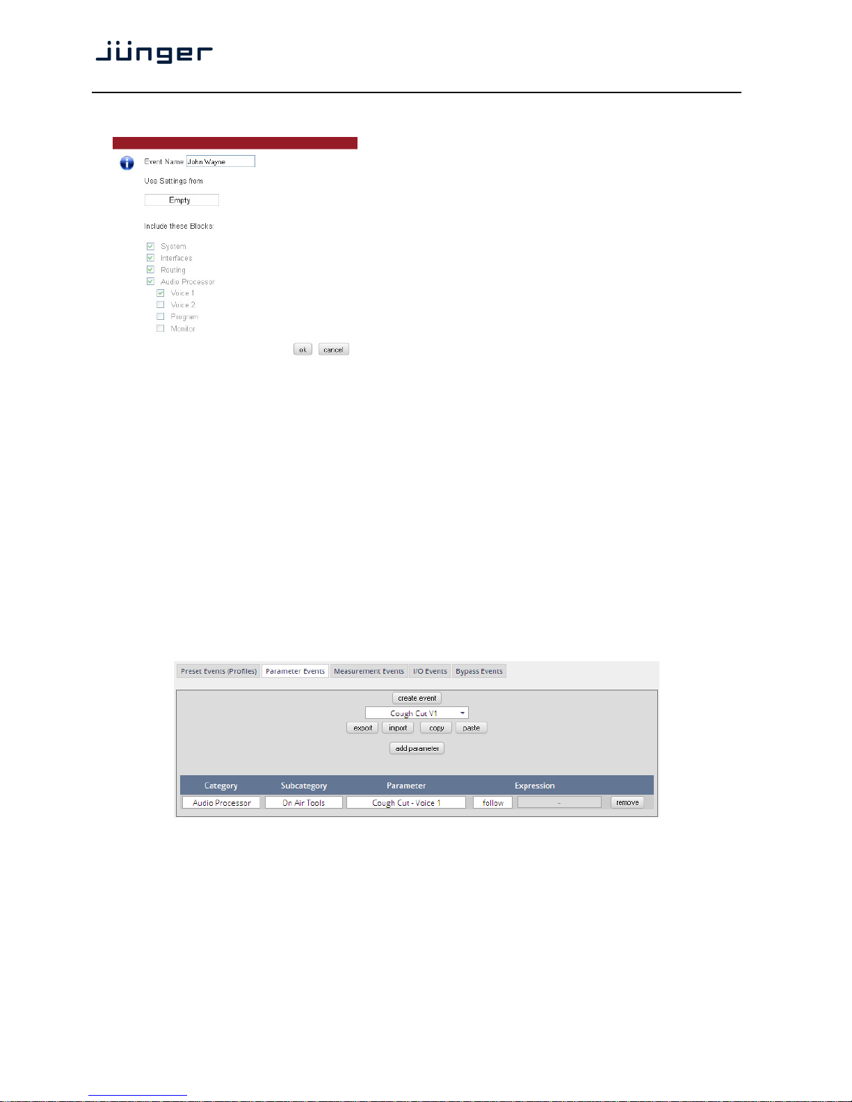
D*AP4 VAP
72
You are able to create a new preset event by pressing <create event>:
Event name [John Wayne]
A unique name to address this preset
event later in the action manager.
.
Use Settings from [ON Air / Existing Event / Empty]
On Air The events manager will copy
all
On Air parameters to new presets
in all function blocks (that have been
selected via the "Include these
Blocks" check boxes).
.
Existing Event The presets of the selected event will
be copied to the new event and may
be marginally tuned afterwards to
form a slightly different event.
Empty Creates a set of empty fields where you may select the preset of
your choice for the respective function block or leave it empty if no
changes are needed …
Include these Blocks [System / Interface / Routing / Audio Processor / Voice 1 / Voice 2 /
Program / Monitor]
You can tell the event manager which function blocks must be
included in this event (or not).
Important note! This is the way to create your own
snap shot. The new presets will be automatically
given the name of this event! So be careful to select meaningful names. You will find them later on in your
function blocks!
Setup GUI – EVENTS – Events – Parameter Events
Parameter events are designed to change parameters when executing an action.
You define the parameter here:
Category [Audio Processor / Measurement]
Subcategory [in case of Category = Audio Processor >> On Air Tools]
[in case of Category = Measurement >> Loudness]
Parameter depending on the pre-selected Subcategory you may define the
relevant parameter which you want to set.
Expression If applicable, the value of the parameter that will be set if the
parameter event is triggered during an event action.
Page 77
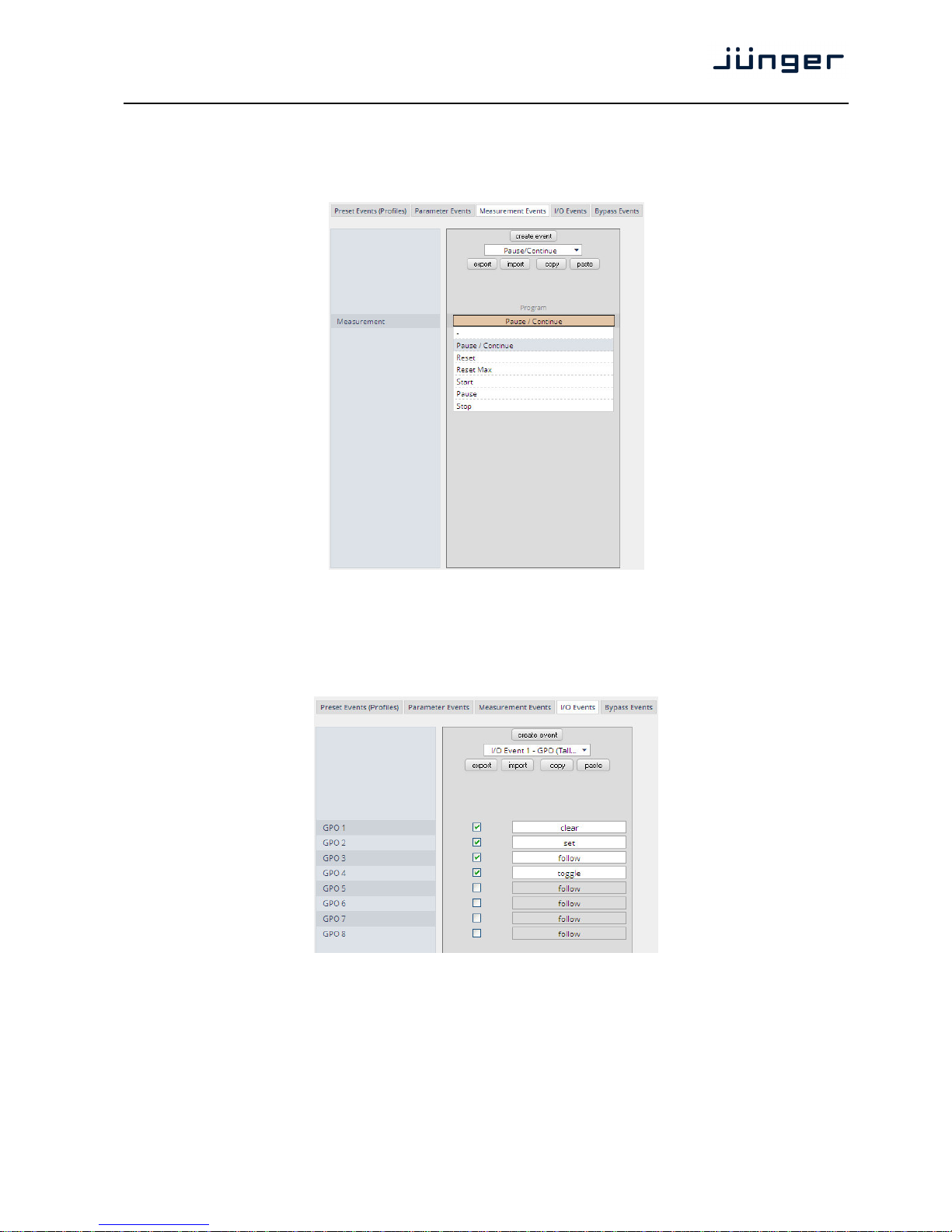
D*AP4 VAP
73
Setup GUI – EVENTS – Events – Measurement Events
Measurement events can be used to control the integrated loudness measurement of the
program path of the D*AP4 VAP:
For each measurement event you can assign one of the possible control functions from the pull-down.
Setup GUI – EVENTS – Events – I/O Events
At the moment I/O events are restricted to control the GPOs of the D*AP4 VAP:
Each GPO (when incorporated into that I/O event) can be set to the behavior as follows:
Clear Turns a GPO off that was previously turned on.
Set Turns a GPO on.
Follow The GPO follows the state of the trigger.
Toggle The trigger will toggle that GPO
Be careful because it needs a definite known starting condition to work
properly.
Page 78
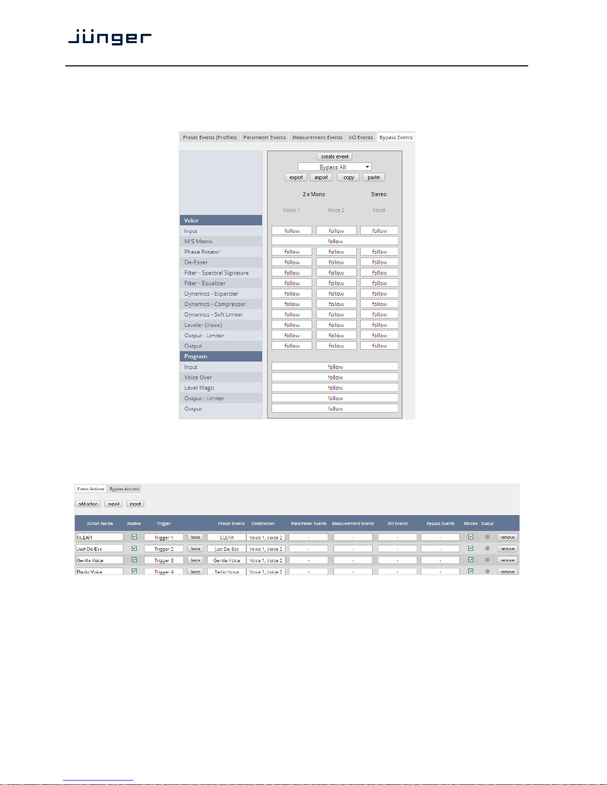
D*AP4 VAP
74
Setup GUI – EVENTS – Events – Bypass Events
The D*AP4 VAP allows you to bypass some or all of the function blocks. This can be used
for A/B comparison for all or for e subset of function blocks:
Setup GUI – EVENTS – Actions – Event Actions
This is the point where all previously defined sub functions will be combined:
You should give actions a meaningful names, select a trigger (from one of the trigger equations) and
select the respective type of events you need to perform the desired action.
Page 79
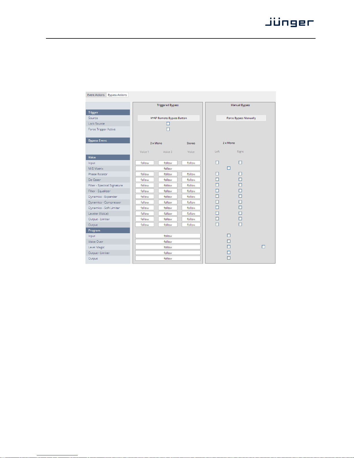
D*AP4 VAP
75
Setup GUI – EVENTS – Actions – Bypass Actions
The bypass action is bound to the <BYPASS> button of the X*AP RM
1
remote panel.
You must simply select "follow" or "-" for the setup field.
But it also allows you to turn the bypass on of one, some or all function blocks by simply enabling the check
boxes in the right hand panel:
Trigger
Source "X*AP Remote Bypass Button"
Lock Source [ON / OFF]
The X*AP RM
1
remote panel <BYPASS> button may be
disabled / enabled here.
Force Trigger Active [ON / OFF]
Force the bypass function from the GUI instead of the
X*AP RM
1
remote panel <BYPASS> button.
Bypass Event "2 x Mono / Stereo"
This is a generic setup page where both modes (2x Mono / Stereo)
can be pre-set.
Voice Audio processing blocks of the voice path.
Input … Output [follow / -]
Define the voice function block that is part of the bypass action.
Program Audio processing blocks of the program path.
Input … Output [follow / -]
Define the program function block that is part of the bypass action.
Page 80

D*AP4 VAP
76
Technical Data - 2 Channel Voice Audio Processor Edition [D*AP4 VAP EDITION]
General
• 2 channel voice processor (mono or stereo)
• 2 channel program path processing
• 2 channel monitor output
• Expandable by hard and software options
Audio Sample Rate 44.1, 48, 88.2, 96kHz, (32 … 196kHz @ input with SRC)
±150ppm sync input capture, ±25ppm master-sync stability
Relevant specifications comply with AES3-X-2009, IEC 60985 and
AES11-2009
2 channels (1 stereo input), XLR-3 connector
24bits, transparent forwarding of PCM and compressed audio (w/o SRC)
24bits, PCM, sample rate converter (SRC) activated
Impedance 110Ohm, differential
Input level 0.3 … 5Vpp @ 110Ohm differential
AES/EBU Input
Sample Rate
Converter (SRC)
THD+N -120dB @ 0dBFS, 1kHz
Latency < 0.3ms
Relevant specifications comply with AES3-X-2009, IEC 60985 and
AES11-2009
2 channels (1 stereo output), XLR-3 connector
24bits, transparent forwarding of PCM and compressed audio
Impedance 110Ohm, differential
Output voltage 3Vpp (typ.) @ 110Ohm differential
AES/EBU Output
Power fail relay bypass between AES/EBU input and output (can be
deactivated by jumper)
Multi-standard synchronization interface for AES/EBU, wordclock or videosync (black burst, tri level), complies with AES11-2009 and relevant audio
or video standards
Connector type BNC
AES/EBU input 0.3 … 5Vpp @ 75Ohm single-ended
Wordclock input 1 … 5Vpp @ 75Ohm single-ended
1Vpp (nom.) @ 75Ohm single-ended Video-sync input
Rates supported: 23.975, 24, 24.975, 25, 29.97,
30, 49.95, 50, 59.94, 60fps (SD and HD)
Sync Input
On-board audio ports and master-sync capable option boards may also be
selectable as sync source.
Word clock output, complies with AES11-2009
Connector type BNC
Sync Output
Wordclock output 2.4V (typ.) @ R = 75Ohm single-ended
Network Interface RJ45 connector, 10/100Mbit Ethernet auto sense, full duplex, auto MDI/X
USB Interface USB 2.0 connector to internal console interface
GPI Signals 8 general purpose inputs (GPI), divided into 2 groups with separate
common signal, isolated
Page 81
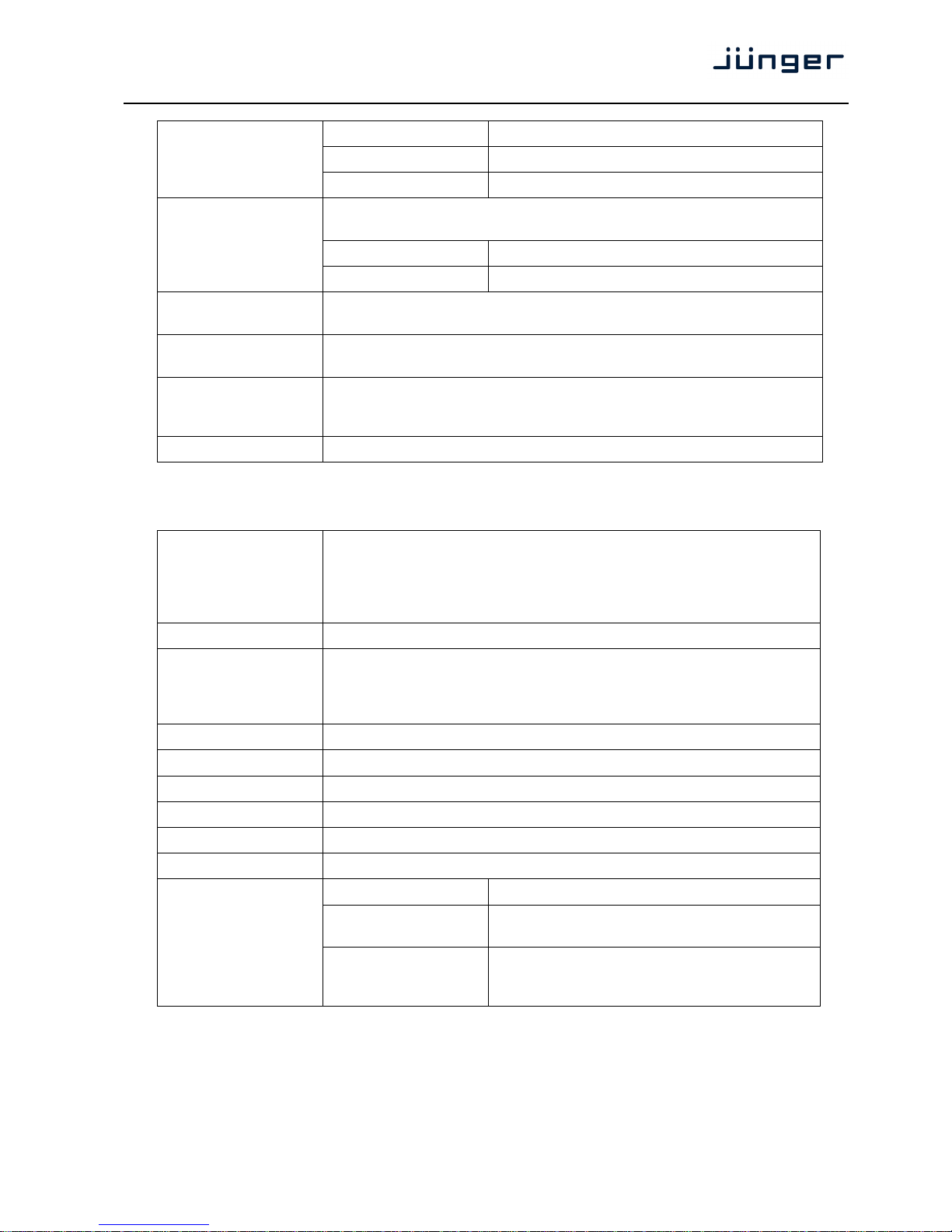
D*AP4 VAP
77
Connector type D-Sub25 connector female, same for GPO
Input conditions 3 … 24Vdc, < 5mA
Auxiliary supply 5V (nom.), 200mA (max.), isolated
8 general purpose outputs (GPO), SPST, divided into 2 groups with
separate common signal, isolated
Connector type D-Sub25 connector female, same for GPI
GPO Signals
Output conditions 24Vac/dc (max.), 120mA (max.)
Expansion Slots 1 general purpose expansion slot for option boards,
1 dedicated expansion slot for 2 microphone inputs [O_DAP_AMIC_a]
Power Supply Dual power supply, automatic fail over,
85 … 264Vac, 50 … 60Hz, 58W (max.)
Environmental Operating temperature 0 … 50ºC, fan cooled,
Non-operating -20 … 70ºC,
Humidity < 90%, non-condensing
Physical 19", 1 RU, 27 cm depth, net weight ca. 5kg, shipping weight ca. 7.5kg
Technical Data – Option Board SDI I/O (3G/HD/SD) [O_DAP_SDI_a]
Standards Video complies with SMPTE 424/425M (3G, Level A and B), SMPTE 292M
(HD) or SMPTE 259M (SD). Automatic format detection.
Audio embedding and de-embedding complies with SMPTE 299M (3G,
HD) or SMPTE 272M-AC (SD).
Metadata embedding and de-embedding complies with SMPTE 2020-2.
Video Data Rate 2970/2967Mbps (3G), 1485/1483.5Mbps (HD), 270Mbps (SD)
Video Formats 1080p23.975, 24, 25, 29.97, 30, 50, 59.94, 60
1080i50, 59.94, 60
720p23.975, 24, 25, 29.97, 30, 50, 59.94, 60
625i50, 525i59.94, …
Video Delay User selectable 0 …15frames, can be disabled
Audio 24bits, transparent forwarding of PCM and compressed audio
Audio Channels 16 inputs and 16 outputs (4 groups with 4 channels each)
Audio Sample Rate 48kHz (SDI compliant)
Audio Delay Embedder audio delay selectable 0 … 320ms per channel
Metadata (RDD6) 1 channel input and 1 channel output, SDID selectable
Impedance 75Ohm
Return loss > 15dB, 5 … 1485MHz
> 10dB, 1485 … 2970MHz
BNC Input
Cable length (max.) 250m @ SD for Belden 1694A cable
230m @ HD for Belden 1694A cable
140m @ 3G for Belden 1694A cable
Page 82
D*AP4 VAP
78
Jitter tolerance > 0.7UI (Alignment)
Impedance 75Ohm
Output voltage 0.8Vpp (typ.)
Return loss > 15dB, 5 … 1485MHz
> 10dB, 1485 … 2970MHz
BNC Output
Output jitter < 0.2UI (Alignment), < 0.5UI (Timing)
Audio Latency Input to Output Embedder and de-embedder combined
HD, 3G < 0.6ms
SD typ. 1.5ms (< 2ms)
General Features
• Power fail relay bypass (may be activated via GUI)
• Lip-Sync compensation for processed and non-processed audio
signals
• Dedicated routing for non-processed channels, all channels
(max. 16) can be routed to/from the device or looped through
• Test pattern generator
• Master-sync capable
• ITU-R BT.1685 / ARIB STD-B39 metadata support
Technical Data – Option Board Analog Line-In and/or Mic-In [O_DAP_AMIC_a]
Audio 24bit sigma-delta A/D-converter
Audio Sample Rate 44.1, 48, 88.2, 96kHz
2 channels, selectable for microphone or line level
Connector type XLR-3
Input level (max.)
(0dBFS equiv.)
Mic: 14dBu @ 0dB gain
Line: 22dBu @ 0dB gain, pad attenuation -10dB
Impedance Mic: 9kOhm (typ.), differential
Line: 20kOhm (typ.), diff., pad attenuation -10dB
THD+N -88dB @ -1dBFS, 1kHz, 0dB gain
Dynamic range > 110dB (RMS)
Crosstalk attenuation > 110dB @ 1kHz (typ.)
CMRR > 60dB @ 1kHz (typ.)
Equivalent input noise -126dBu (RMS) (typ.) @ 65dB gain
Frequency response 20Hz … 22kHz (< ±0.1dB) @ 48kHz
20Hz … 43kHz (< ±0.1dB) @ 96kHz
Preamp gain 0dB, 10 … 65dB in 1dB steps
Inputs
Pad attenuation -10dB
Phantom Power 48V (nom.) enable per input channel, individual short-circuit protection
General Features
• Floating, balanced analog inputs
• Electrical isolation between both channels and device
• Digitally controlled input gain 0 … 65dB
Page 83

D*AP4 VAP
79
Technical Data – Option Board Analog Out [O_DAP_8DA_a]
Audio 24bit D/A-converter
Audio Channels 8 output channels (e.g. for speakers)
Audio Sample Rate 44.1, 48, 88.2, 96kHz
8 channels
Connector type D-Sub25 connector female
Output Level (max.)
(0dBFS equiv.)
0 … 24dBu, adjustable in 0.5dB steps
Impedance 50Ohm (typ.), differential
THD+N -91dB @ 0dBFS = 15dBu, 1kHz
Dynamic range > 103dB (RMS)
Crosstalk attenuation > 103dB @ 0dBFS = 15dBu, 1kHz
Analog Outputs
Frequency response 20Hz … 22kHz (< ±0.3dB) @ 48kHz
20Hz … 43kHz (< ±0.3dB) @ 96kHz
General Features
• Power fail glitch prevention
• Balanced analog outputs
• Electrical isolation between outputs and device
Technical Data – Option Board Analog I/O [O_DAP_ADDA_a]
Audio 24bit sigma-delta A/D-converter, 24bit D/A-converter
Audio Channels 4 input channels, 4 output channels
Audio Sample Rate 44.1, 48kHz
4 channels
Connector type D-Sub25 connector female, same for outputs
Input Level (max.)
(0dBFS equiv.)
0 … 24dBu, adjustable in 0.5dB steps
Impedance 20kOhm (typ.), differential
THD+N -93dB @ 0dBFS = 15dBu, 1kHz
Dynamic range > 110dB (RMS)
Crosstalk attenuation > 93dB @ 0dBFS = 15dBu, 1kHz
Analog Inputs
CMRR > 71dB @ 0dBFS = 15dBu, 1kHz
Page 84
D*AP4 VAP
80
Frequency response 20Hz … 22kHz (< ±0.1dB) @ 48kHz
20Hz … 43kHz (< ±0.1dB) @ 96kHz
4 channels
Connector type D-Sub25 connector female, same for inputs
Output Level (max.)
(0dBFS equiv.)
0 … 24dBu, adjustable in 0.5dB steps
Impedance 50Ohm (typ.), differential
THD+N -91dB @ 0dBFS = 15dBu, 1kHz
Dynamic range > 103dB (RMS)
Crosstalk attenuation > 103dB @ 0dBFS = 15dBu, 1kHz
Analog Outputs
Frequency response 20Hz … 22kHz (< ±0.3dB) @ 48kHz
20Hz … 43kHz (< ±0.3dB) @ 96kHz
General Features
• Power fail relay bypass between inputs and outputs
• Balanced analog inputs and outputs
• Electrical isolation between inputs, outputs and device
Technical Data – Option Board AES/EBU I/O [O_DAP_AES_a]
Standards Relevant specifications comply with AES3-X-2009, IEC 60985 and
AES11-2009
Audio 24bits, transparent forwarding of PCM and compressed audio (w/o SRC)
24bits, PCM, sample rate converter (SRC) activated
Audio Sample Rate 44.1, 48, 88.2, 96kHz, (32 … 196kHz @ inputs with SRC)
8 channels (4 stereo inputs)
Connector type D-Sub25 connector female, same for outputs
Impedance 110Ohm or 75Ohm, jumper selectable
(110Ohm default)
Input level 0.3 … 5Vpp @ 110Ohm differential
0.3 … 5Vpp @ 75Ohm single-ended
Inputs
Sample Rate
Converter (SRC)
THD+N -120dB @ 0dBFS, 1kHz
Latency < 0.3ms
8 channels (4 stereo outputs)
Connector type D-Sub25 connector female, same for inputs
Impedance 110Ohm or 75Ohm, jumper selectable
(110Ohm default)
Outputs
Output voltage 3Vpp (typ.) @ 110Ohm differential
1Vpp (typ.) @ 75Ohm single-ended
General Features
• Power fail relay bypass (can be deactivated by jumper)
• Input sample rate converters (SRC)
• Electrical isolation between inputs, outputs and device (if
configured for differential mode, 110Ohm)
• AES3 channel status management, non-audio detection
• Master-sync capable
Page 85
D*AP4 VAP
81
Technical Data – Option Board MADI I/O, BNC [O_DAP_MB_a]
Standards Relevant specifications comply with AES10-2008 and AES11-2009.
Audio 24bits, transparent forwarding of PCM and compressed audio
Audio Sample Rate 44.1, 48, 88.2, 96kHz, (88.2, 96kHz short framing)
64/56 channels @ 44.1 and 48kHz, 32/28 @ 88.2 and 96kHz
Processable by D*AP8: 16 channels @ 44.1, 48kHz
Processable by D*AP4: 8 channels @ 44.1, 48, 88.2, 96kHz
Impedance 75Ohm
Input level 0.15 … 0.8Vpp @ 75Ohm
BNC Input
Cable length (max.) 150 m (Belden 1694A)
64/56 channels @ 44.1 and 48kHz, 32/28 @ 88.2 and 96kHz
Processable by D*AP8: 16 channels @ 44.1, 48kHz
Processable by D*AP4: 8 channels @ 44.1, 48, 88.2, 96kHz
Impedance 75Ohm
BNC Output
Output voltage 0.6Vpp (typ.) @ 75Ohm
General Features
• Input cable equalizer for extended range and robustness
• Reference grade word clock recovery, master-sync capable
• Dedicated routing for non-processed channels, all channels
(max. 64) can be routed to/from the device or looped through
• AES3 channel status management, non-audio detection
Technical Data – Option Board MADI I/O, Optical [O_DAP_MO_MM_a, O_DAP_MO_SM_a]
Standards Relevant specifications comply with AES10-2008 and AES11-2009.
Audio 24bits, transparent forwarding of PCM and compressed audio
Audio Sample Rate 44.1, 48, 88.2, 96kHz, (88.2, 96kHz short framing)
64/56 channels @ 44.1 and 48kHz, 32/28 @ 88.2 and 96kHz
Processable by D*AP8: 16 channels @ 44.1, 48kHz
Processable by D*AP4: 8 channels @ 44.1, 48, 88.2, 96kHz
Connector type LC (IEC 61754-20)
Center wavelength 1310nm (typ.), 1270 … 1360nm
Optical Input, LC
Input optical power [O_DAP_MO_MM_a]:
-31 … -8dBm, OM2 multimode (50/125µm)
[O_DAP_MO_SM_a]:
-23 … -8dBm, singlemode (9/125µm)
(standard values, others on request)
Page 86
D*AP4 VAP
82
Cable length (max.) [O_DAP_MO_MM_a]: 1.5km, OM2 multimode
[O_DAP_MO_SM_a]: 2km, singlemode
(standard values, others on request)
64/56 channels @ 44.1 and 48kHz, 32/28 @ 88.2 and 96kHz
Processable by D*AP8: 16 channels @ 44.1, 48kHz
Processable by D*AP4: 8 channels @ 44.1, 48, 88.2, 96kHz
Connector type LC (IEC 61754-20)
Center wavelength 1310nm (typ.), 1270 … 1360nm
Optical Output, LC
Output optical power [O_DAP_MO_MM_a]:
-23 … -14dBm, OM2 multimode (50/125µm)
[O_DAP_MO_SM_a]:
-15 … -8dBm, singlemode (9/125µm)
(standard values, others on request)
Optical and BNC output carry the same signal.
Impedance 75Ohm
BNC Output
Output voltage 0.6Vpp (typ.) @ 75Ohm
General Features
• Field-replaceable optical module (SFP)
• Reference grade word clock recovery, master-sync capable
• Dedicated routing for non-processed channels, all channels
(max. 64) can be routed to/from the device or looped through
• AES3 channel status management, non-audio detection
• Parallel outputs (BNC/LC) for media conversion
Technical Data – Option Board Audio-over-IP DANTE™ I/O [O_DAP_DANTE_a]
Standards Audio-over-IP by Dante™ Digital Audio Networking Standard
Audio 24bits, transparent forwarding of PCM and compressed audio
Audio Sample Rate 44.1, 48, 88.2, 96kHz
Inputs and Outputs 2 x Gigabit Ethernet RJ45 connectors (100M/1Gbit),
primary and secondary port
Inputs Processable by D*AP8: 16 channels @ 44.1, 48kHz
Processable by D*AP4: 8 channels @ 44.1, 48, 88.2, 96kHz
Outputs Processable by D*AP8: 16 channels @ 44.1, 48kHz
Processable by D*AP4: 8 channels @ 44.1, 48, 88.2, 96kHz
General Features
• AES67 compliant (when available)
• Network master-sync can be provided by D*AP device
• Master-sync capable (for D*AP device)
• Non-audio detection for input channels
• Glitch-free Dante™ audio redundancy using dual Ethernet
networks
Page 87
D*AP4 VAP
83
connector:
GPI/O
female 25-pin D-Sub
1 GPI_1, 2, 3, 4 common
2 GPI_1
3 GPI_2
4 GPI_3
5 GPI_4
6 GPI_5, 6, 7, 8 common
7 GPI_5
8 GPI_6
9 GPI_7
10 GPI_8
11
12
13
Isolated 5V
+
14 GPO_1, 2, 3, 4 common
15 GPO_1
16 GPO_2
17 GPO_3
18 GPO_4
19 GPO_5, 6, 7, 8 common
20 GPO_5
21 GPO_6
22 GPO_7
23 GPO_8
24
Isolated 5V
-
25
Isolated 5V
-
Technical Data - Rear Connectors - pin assignment
8x GPI/O Mic / Line IN
connector:
Mic / Line input
female XLR
1 GND
2 IN +
3 IN -
Shield Virtual GND
Page 88
D*AP4 VAP
84
connector: 4 x analog I/O
female 25-pin D-Sub
1 OUT-4 +
2 GND
3 OUT-3 4 OUT-2 +
5 GND
6 OUT-1 7 IN-4 +
8 GND
9 IN-3 10 IN-2 +
11 GND
12 IN-1 13
14 OUT-4 15 OUT-3 +
16 GND
17 OUT-2 18 Out-1 +
19 GND
20 IN-4 21 IN-3 +
22 GND
23 IN-2 24 IN-1 +
25 GND
Technical Data - Optional Interface Modules – pin assignment
4x analog I/O [O_DAP_ADDA_a] 4x AES I/O [O_DAP_AES_a] 8x analog out [O_DAP_8DA_a]
connector:
4x AES I/O
female 25-pin D-Sub
1 OUT-4 +
2 GND
3 OUT-3 4 OUT-2 +
5 GND
6 OUT-1 7 IN-4 +
8 GND
9 IN-3 10 IN-2 +
11 GND
12 IN-1 13
14 OUT-4 15 OUT-3 +
16 GND
17 OUT-2 18 OUT-1 +
19 GND
20 IN-4 21 IN-3 +
22 GND
23 IN-2 24 IN-1 +
25 GND
connector: 8 x analog out
female 25-pin D-Sub
1 OUT-8 +
2 GND
3 OUT-7 4 OUT-6 +
5 GND
6 OUT-5 7 OUT-4 +
8 GND
9 OUT-3 10 OUT-2 +
11 GND
12 OUT-1 13
14 OUT-8 15 OUT-7 +
16 GND
17 OUT-6 18 OUT-5 +
19 GND
20 OUT-4 21 OUT-3 +
22 GND
23 OUT-2 24 OUT-1 +
25 GND
Page 89
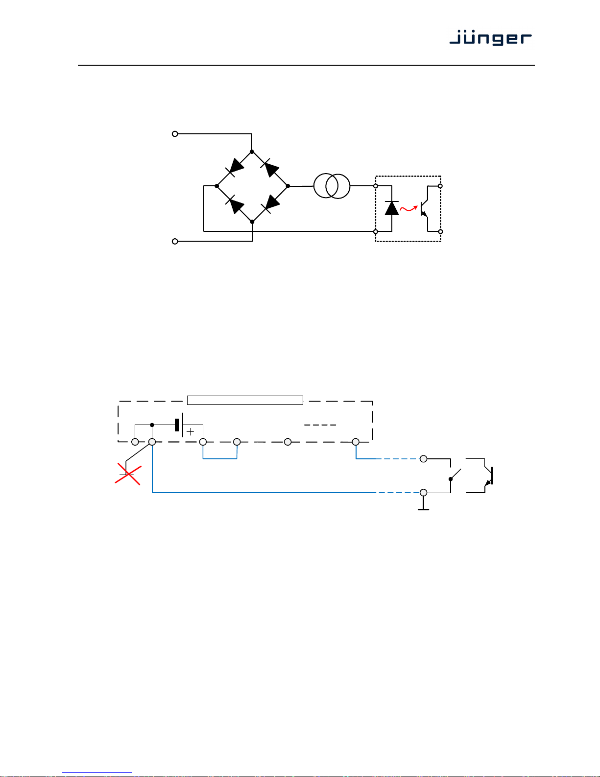
D*AP4 VAP
85
Technical Data - GPI wiring
The device offers a unique circuitry to save GPI setups from hum and noise influence in complex
installations. Here the principle circuit of one of the eight GPI inputs:
At the GPI input is a bridge rectifier I.e. you do not need to care about the polarity of the input voltage.
A constant current source in line with the optical coupler limits the current.
You must simply provide a voltage in the range from 5V to 30V to activate a GPI.
If you have open collector outputs or simple relay closures as the driving GPOs (this technique is commonly
known as "low active" and will be found in most legacy equipment),
you must wire up an auxiliary voltage supply.
The device provides such auxiliary power supply. It offers a balanced 5V source that you can imaging
as a battery.
Here an example how to wire up GPI #4:
We strongly recommend to spent a wire for ground connection instead of using the chassis common grounds
of an installation.
GPI
common
GPI_x
5 V balanced
1324 25
1
GPI 1, 2, 3, 4
common
GPI 1
2
GPI 4
5
GPO
relay or open collector
25 pin GPI/O connector
Page 90

D*AP4 VAP
86
Safety Information
Electrical
Safety classification: Class 1 – grounded product / Schutzklasse 1
Corresponding to EN 60065:2002
Power connection: The device must be connected to a power socket that provides a
protective earthing conductor.
Power switch: The power switch is a toggle switch placed at the rear of the device.
The ON / OFF position is indicated by engravings [I] / [o] on the lever. It must be
reached without difficulty.
The devices may be equipped with dual power supply, in this case it will have
two power cords and switches. You must inform yourself about the location and
assignment of the switches.
Water protection: The device must not be exposed to splash or dripping water.
It is permitted to place a container filled with liquids (e.g. vases)
on top of the device.
Service safety Only qualified personnel should perform service procedures.
Do not service alone: Do not perform internal service or adjustments of the device unless another
person capable of rendering first aid and resuscitation is present.
Disconnect power: To avoid electrical shock, switch off the device power, then disconnect the
power cord from the mains power. Do not block the power cord; it must remain
accessible to the user at all times
To avoid fire or personal injury
Mounting: It must be placed on a flat surface or must be mounted into an 19" rack.
It is recommended to use metal brackets (sheet steel angle) to support the
device.
Provide proper this case and if the device has a built in fan, a gap of at least 1cm must be
Ventilation left between the device edge and the steel angle. It is highly recommended to
leave a gap of at least 1RU above and below the device.
Use proper power cord Use only the power cord specified for this product and certified for the country of
use.
Do not operate Do not operate this product with covers or panels removed.
without covers
Do not operate If you suspect that there is damage to this product, have it inspected
with suspected failures by qualified service personnel.
Risk of explosion: The device contains a lithium battery. If replaced incorrectly or by a different or
inadequate type an explosion may occur.
Warranty
Standard Junger Audio one-year warranty on parts and labor.
Specifications are subject to change without notice
Page 91

Page 92

SLIM LINE
Headquarters
Jünger Audio GmbH
Sales • Service & Support
Justus-von-Liebig-Str. 7
12489 Berlin, Germany
phone +49 30 677 721 0
fax +49 30 677 721 46
[email protected]
[email protected]
www.jungeraudio.com
Jünger Audio Asia
Junger Audio Pte. Ltd.
Sales • Service & Support
33, Ubi Ave 3, no. 06-62 Vertex
408868 Singapore
phone +65 6509 8171
fax +65 6748 1740
[email protected]
Jünger Audio (China Office)
Junger (Beijing) Technology Ltd.
Sales • Service & Support
Unit 068, 2nd Floor, No. 38 GuangQu Road,
ChaoYang District, 100021 Beijing, China
phone +86 137 0102 6664
[email protected]
Jünger Audio USA
Service & Support
2100 B2 Walsh Ave
Santa Clara, CA 95050-2590, USA
phone +1 408 330 9215
© 2017 Jünger Audio GmbH
All rights reserved. All trademarks are the property of their respective owners. Product specifications are subject to change without notice.
This material is provided for information purposes only; Jünger assumes no liability related to its use
www.facebook.com/jungeraudio www.twitter.com/jungeraudio
 Loading...