

Page 1
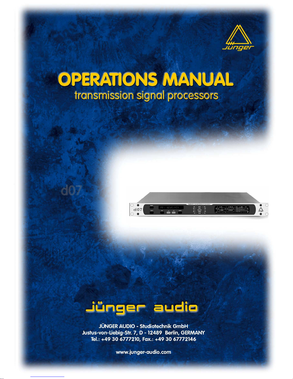
digital transmission processor
d07
release 4.1
Page 2

Page 3

FOREWORD
FOREWORD
Thank you for buying and using the transmission processor d07.
You have not only acquired the latest generation of digital dynamic range
processing, but also a piece of equipment which is unique in its design and
specification.
Please read this manual carefully to ensure you have all the information you need
to use the d07.
The unit was manufactured to the highest industrial standards and went through
extensive quality control checks before it was supplied.
If you have any comments or questions about installing, setting-up or using the,
please do not hesitate to contact us.
d07
Page 4

CONTENTS
CONTENTS
A – OPERATION MANUAL
1. Function description
1.1. Basic description
1.2. Block diagram
2. Installation
2.1. Unpack the unit
2.2. Power supply
2.3. Connections
2.4. Rack mounting
2.5. Operation safety
2.6. Synchronization of digital output
2.7. Audio connections
2.8. Remote Control
2.8.1. GPI Remote Control
2.8.2. Tally Out
2.8.3. Serial Remote Control
2.9. LAN interface (optional)
3. Location of parts and controls
3.1. Front panel
3.2. Rear panel
3.3. Switches and jumpers for configuration
4. Operation
4.1. Front panel operation / d07 keys
4.1.1. Navigation
4.1.2. Main Display
4.1.3. Menu Preset / Setup
4.1.4. Factory presets
4.1.5. User presets
4.2. Operation via web interface
4.2.1. web interface of the d07
4.2.2. Maintenance
4.2.3. DATA transfer
5. Boot display and trouble shooting
5.1. Boot display
5.2. Error messages and trouble shooting
5.3. Initialization of the unit
6. Technical specifications
d07
Page 5

CONTENTS
B – APPLICATION NOTES
1. The Junger Audio Dynamics Processor Principle
2. The Junger Audio Compressor & Expander Principle
3. The Junger Audio Processing Presets
4. LEVEL MAGIC
5. GUI
6. Network Integration for TCP/IP Operation
7. FM-Processing d07
7.1. General
7.2. MPX-Limiting
7.3. Pre-emphasis
7.4. Terms and definitions
Page 6

Page 7

A 1 –Function description
FUNCTIONAL DESCRIPTION
The mature technology of the digital transmission processor d07
has now been supplemented by the Level Magic™. The d07 is
originally designed for optimised levelling of program signals for
FM broadcast and TV transmission and reliable protection of
transmission paths against overload at the output of studios, OB
vans as well as satellite up-links. The device operates fully
digitally and, beside AES/EBU interface, it makes use of high end
24bit A/D converters so that digital dynamic processing is
possible for analog as well as digital signals.
Besides the previous levelling by means of an AGC, Compressor
and Peak-Limiter referring to the peak- level for achieving the
maximum loudness and energy of the signal, it’s now possible to
use the more signal wave adaptive new technology of the Level
Magic™ with two reference levels: An Operating-Level for signal
processing by the AGC and the Transient processor and the peakLevel for the Brickwall-Limiter.
In both operating methods you can factor the adaptive preemphasis, the maximum value for the peak frequency deviation
and the MPX-Limiter into levelling of the signal (see application
notes).
The dynamic range processor principles developed by Junger
Audio enable level managing devices like compressors, AGC
and limiters to be produced with exceptionally high audio quality,
without coloration, pumping, breathing, distortion or modulation
effects sometimes associated with this type of processor.
In short, almost inaudible processing - with ease of use. The
outstanding quality of the processing is based on the Multi-Loop
dynamic range control principle in combination with adaptive
controlled processing algorithms developed by Junger Audio.
The unit is easy to operate and requires only a limited number of
settings to be made by the user to achieve optimum results. All
other parameters necessary for inaudible processing are
continuously automatically controlled in response to changes in
the programme signal.
1.1
BASIC
DESCRIPTION
A 1
Page 8
A 1 – Function description
features
2-channel digital audio amplifier and limiter for broadcast
transmission signals
new Level Magic™ technology
audio signal processing also in consideration of pre-emphasis
and MPX-Power
Digital I/Os, AES/EBU format
24bit ADV and DAC
Stereo and dual channel mode
Parallel and serial remote control
Equal functionalitiy to the processor C8007 of the C8000
modular system
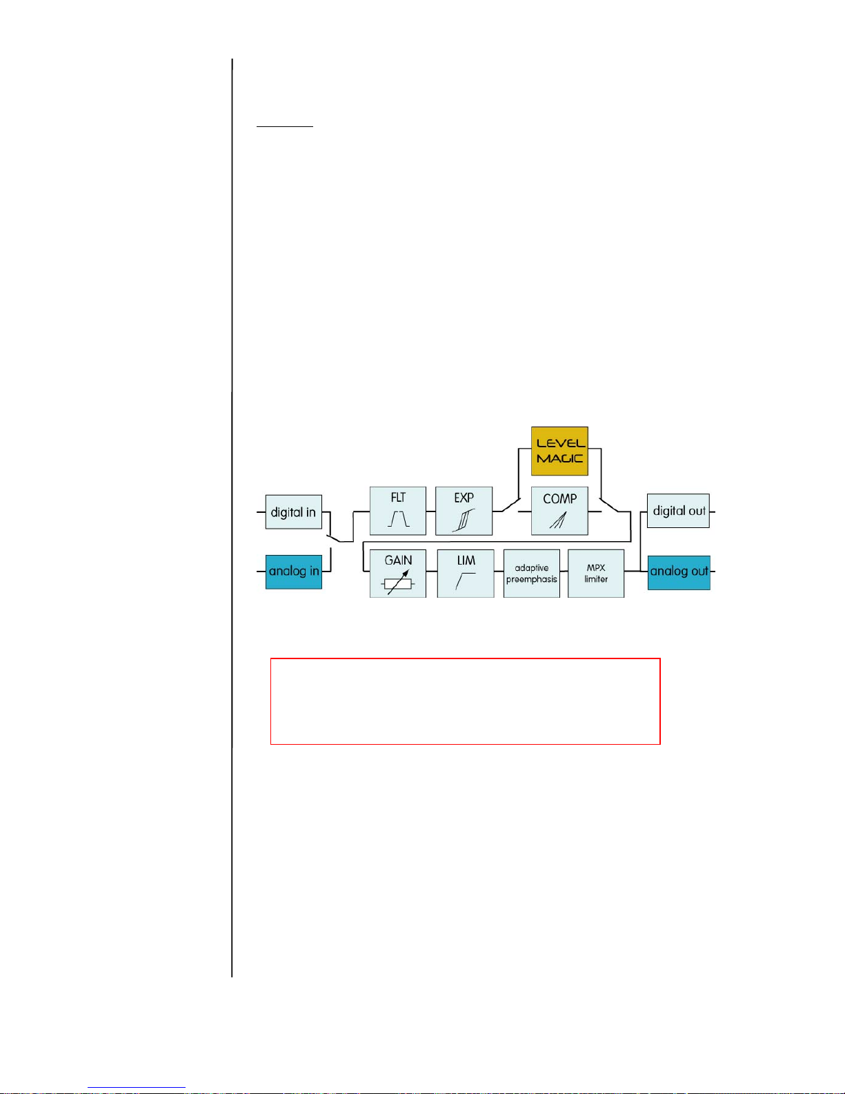
1.2
BLOCK
DIAGRAM
Further description of the processor principles see
Application notes B!
Page 9

A 2 –Installation
INSTALLATION
The digital audio level processor d07 was carefully packed in the factory and
the packaging was designed to protect the equipment from rough handling.
Please examine carefully the packaging and its contents for any signs of
physical damage, which may have occured in transit.
The digital audio level processor d07 is a device under the safety category
Schutzklasse 1 in keeping with the VDE 0804 standards and may only used
with power supply installations built according to regulations.
Check the voltage details printed at the rear panel are the same as your local
mains electricity supply.
The digital audio level processor d07 is equipped with standard connectors
(see also chapter 3).
Before connecting the digital audio level processor d07 switch the power off at
all connected units.
The digital audio level processor d07 is made as standard 19“ unit (EIA
format). It occupies 1 RU (44 mm height) space in a rack. Please allow at
least additional 3“ depth for the connectors on the rear panel.
When installing the unit in a 19“ rack the rear side of the unit needs some
support, especially for mounting in flight cases.
The digital audio level processor d07 should not be installed near units which
produce strong magnetic fields or extreme heat. Do not install the audio
processor directly above or below power amplifiers.
If, during operation, the sound is interrupted or displays no longer illuminate,
or if abnormal odor or smoke is detected immediately disconnect the power
cord plug and contact your dealer or Jünger Audio.
2.1
UNPACK THE UNIT
2.2
POWER SUPPLY
2.3
CONNECTIONS
2.4
RACK MOUNTING
2.5
OPERATION
SAFETY
A 2
Page 10

A 2 –Installation
The digital transmission processor d07 has a digital signal output. For the
problem-free combination of following digital devices, the digital signal
processing can be locked to an external clock reference. The selection of the
corresponding sync source is made in the SYNC MODE menu during setup. If
the chosen sync input is connected with the sync signal, this signal is used for
synchronization automatically. All sync sources can be used for locking A/Dconverters at the analogue inputs as well. The digital output signal can be
clocked with the following clock frequencies:
INTERNAL locks both the A/D-converters and the digital output with
the internal reference 44,1 or 48 kHz. Digital inputs are
connected via sample rate converter
AES INPUT locks with the clock frequency of the input signal at
digital input CH 1/2 (AES/EBU, 44,1...48 kHz)
EXT AES locks with the AES signal at the sync input
(AES, 44,1...48 kHz) Digital inputs are connected via sample
rate converter
EXT WCLK locks with the word clock signal at the sync input
(WCLK, 44,1...48 kHz) Digital inputs are connected via sample
rate converter
optional:
EXT VIDEO locks with black burst at sync input (internal 48 kHz) Digital
inputs are connected via sample rate converter
The analog audio inputs are RFI filtered and analogue outputs are balanced
and floating like transformer coupled devices. All the audio connectors are via
rear panel mounted connectors. Standard XLR connectors are used. These
are always wired to the AES standard:
pin 1 X Screen screen
pin 2 L Live audio 0°
pin 3 R Return audio 180°.
Balanced connections are preferred whenever the other equipment provides
balanced inputs/outputs. All line level connections should be wired with twin
screened cable for low noise and reliability. The screens of the cable should
be connected at one end only. Input cable screening therefore needs to be
derived from the signal source end as pin 1 is ground lifted at low frequencies
for the inputs.
If the equipment driving the digital audio level processor d07 has unbalanced
outputs then you will need to add a wire jumper such that the screen
connection of Pin 1 of the XLR is shorted to Pin 3.
If the equipment being connected to the d07 have only unbalanced inputs,
then we recommend still to use a balanced (ie. 2 core shielded cable) cable
where Pin 1 and Pin 3 are connected in the cable ends away from the digital
audio level processor d07.
2.6
SYNCHRONIZATION
OF
DIGITAL OUTPUT
2.7
AUDIO
CONNECTIONS
Page 11
A 2 –Installation
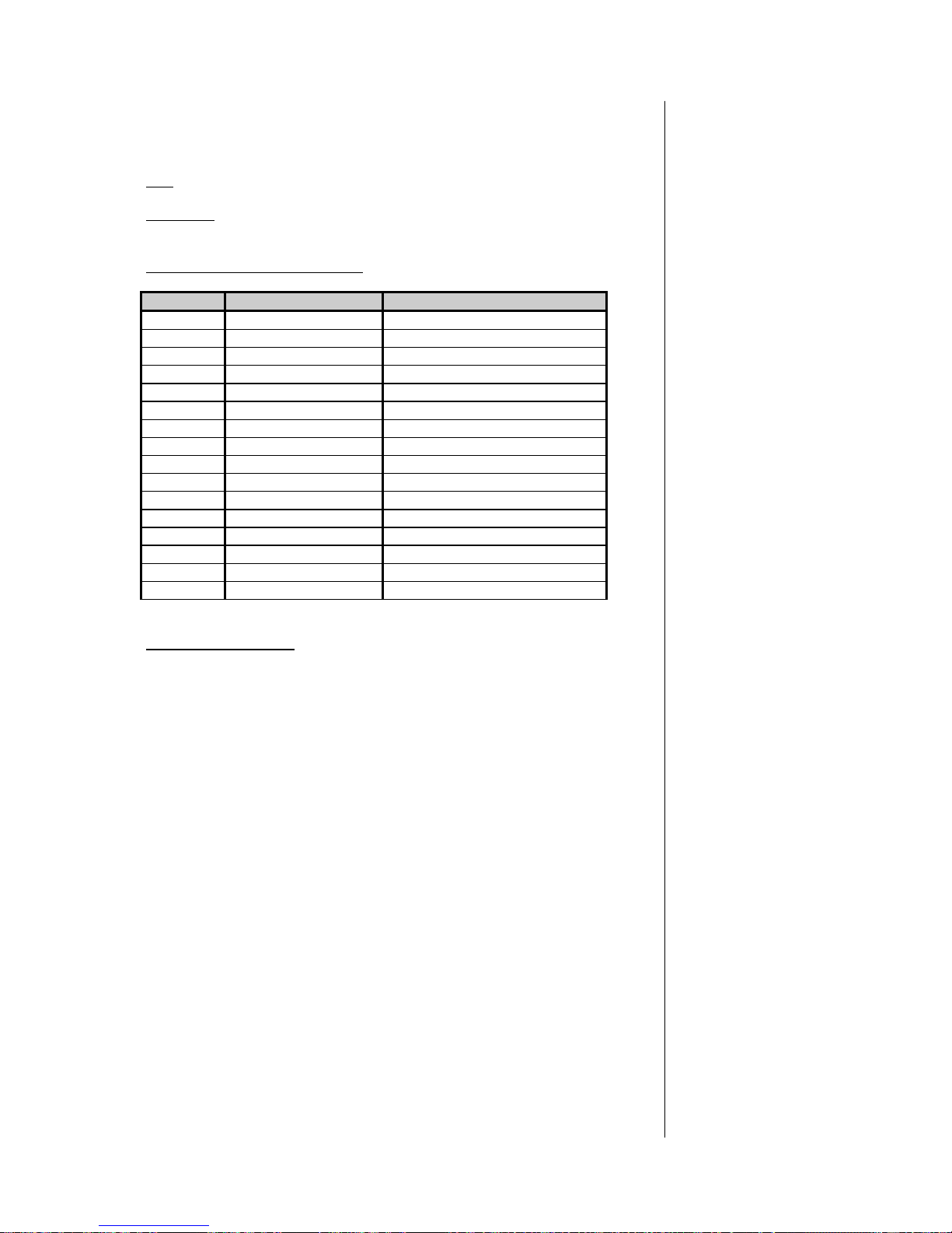
The digital audio toolbox b40 can be remote-controlled by means of parallel
GPI contacts.
use
: remote-controlled changeover of presets
connector:
D-SUB 15pin, female
Pin assignment of the connector :
Pin Signal name Functions
1 GPI1 in Defined by d07 config
2 GPI2 in Defined by d07 config
3 GPI3 in Defined by d07 config
4 GPI4 in Defined by d07 config
5 GPI5 in Defined by d07 config
6 GPI6 in Defined by d07 config
7 GPI7 in Defined by d07 config
8 GPI8 in Defined by d07 config
9 + 5V 110Ohm
10 GPI1/GPI2 common
11 GPI3 common
12 GPI4 common
13 GPI5 common
14 GPI6 common
15 GPI7/GPI8 common
Shield GND
Electrical specification:
GPI input potential free by opto-coupler witt current source
OFF : +3.5…+30V between GPIx input
and GPx common
ON : less then 1.5V betwee GPIx input
And GPIx common
signal duration 3.5 … 30V for at least 50msec.
Note : An internal auxiliary voltage feed is available on pin 9 via a 110Ohm
resistor. Ground is available from the shield of the connector only! When
using the auxiliary voltage feed, there is no electrical isolation given anymore
and the risk to inject unwanted noise is high!
2.8
REMOTE
CONTROL
2.8.1
GPI REMOTE
CONTROL
(PARALLEL
REMOTE)
Page 12
A 2 –Installation
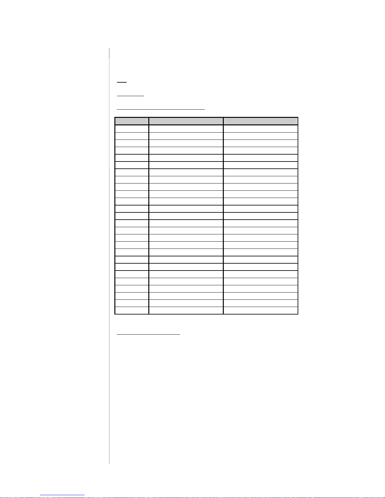
The digital audio level processor d07 can transmit specific device statuses
via parallel Tally lines.
use
: monitoring of the d07 status
Connector
: D-SUB 25pin, female
Pin assignment of the connector :
Pin Signal name Functions
1 Tally 1 normally closed
2 Tally 1 normally opened Defined by d07 config
3 TALLY 2 common
4 Tally 3 normally closed
5 Tally 3 normally opened Defined by d07 config
6 TALLY 4 common
7 Tally 5 normally closed
8 Tally 5 normally opened Defined by d07 config
9 Tally 6 common
10 Tally 7 normally closed
11 Tally 7 normally opened Defined by d07 config
12 TALLY 8 common
13 + 5V 110 Ohm
14 TALLY 1 common
15 Tally 2 normally closed
16 Tally 2 normally opened Defined by d07 config
17 TALLY 3 common
18 Tally 4 normally closed
19 Tally 4 normally opened Defined by d07 config
20 TALLY 5 common
21 Tally 6 normally closed
22 Tally 6 normally opened Defined by d07 config
23 TALLY 7 common
24 Tally 8 normally closed
25 Tally 8 normally opened Defined by d07 config
Shiled
Electrical specifications:
GPO (Tally) potential free relay contact
common / normally closed / normally opened
24V - 1A
125V - 0,5A
P
max
= 62,5VA
Note : An internal auxiliary voltage feed is available on pin 9 via a 110Ohm
resistor. Ground is available from the shield of the connector only!
When using the auxiliary voltage feed, there is no electrical isolation given
anymore and the risk to inject unwanted noise is high!
2.8.2
TALLY OUT
Page 13
A 2 –Installation
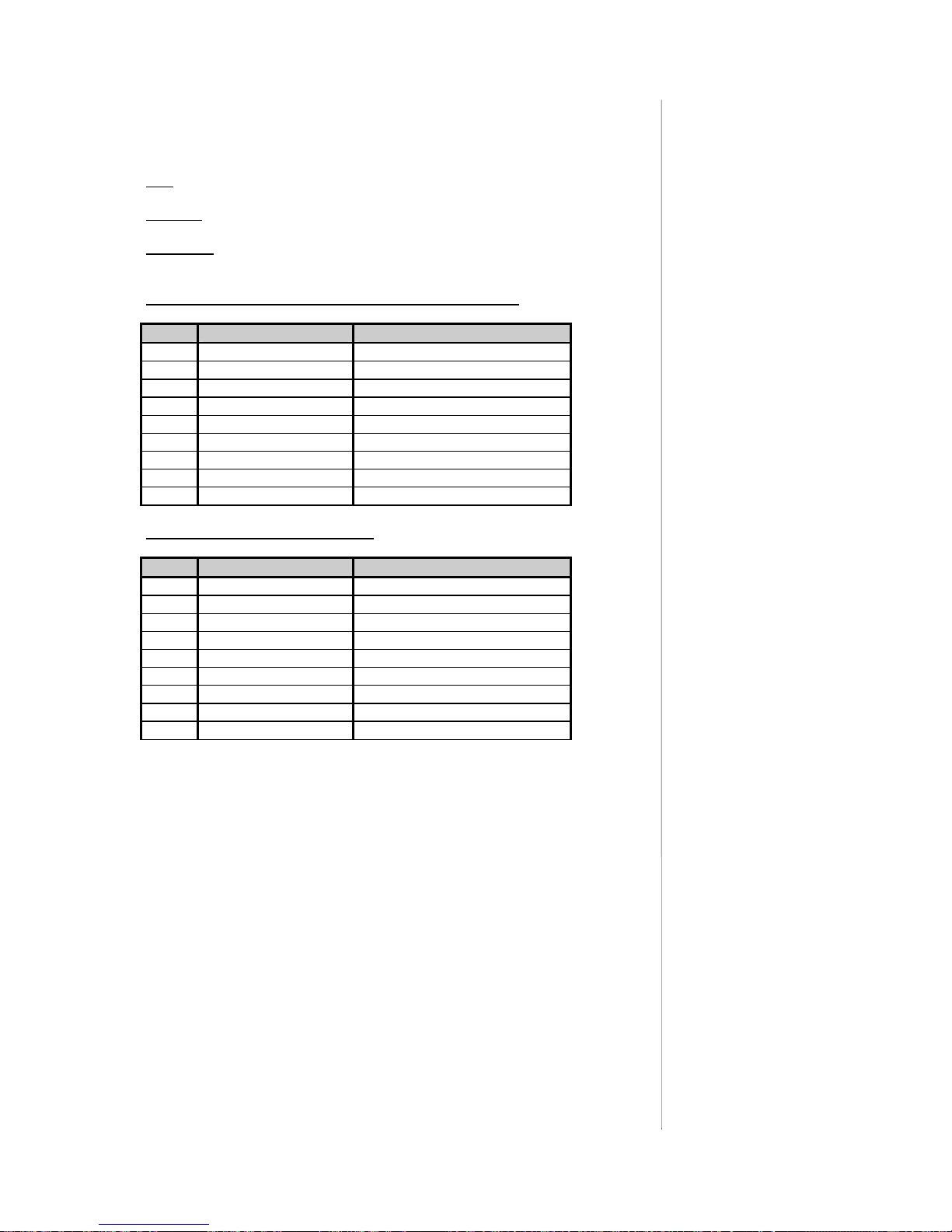
The d07 can be remote-controlled by means of serial remote RS-232/422 or
via the CAN-bus.
use
: remote-controlled changeover of presets
protocol:
available on request
Connector
: D-SUB 9pin, female
Pin assignment of the connector in serial interface mode :
Pin Signal name Functions
1 Rx + RS422
2 TxD RS232
3 RxD RS232
4 NC not used
5 GND Ground
6 Rx - RS422
7 NC not used
8 Tx - RS422
9 Tx + RS422
Pin assignment in CAN-bus mode :
Pin Signal name Functions
1 NC Not used
2 CAN-l CAN-bus low signal
3 NC Not used
4 NC Not used
5 GND Ground
6 GND Ground
7 CAN-H CAN-bus high signal
8 NC Not used
9 NC Not used
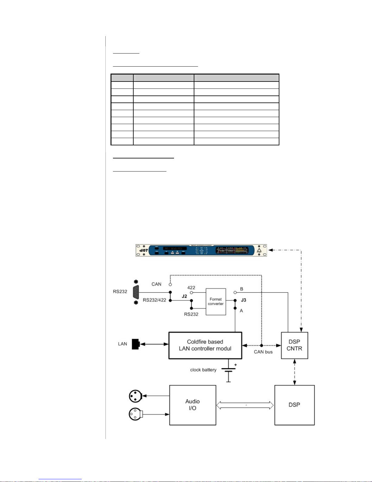
This connector has multiple functions which may be internally changed by
connectors and jumpers. The factory default format setting is RS232 and the it
is connected with the serial interface of the LAN Controller.
By using a terminal program (115kB/sec. 8,N,1 no flow control) you may
communicate with the consol of the LAN Controller, e.g. to change the IP
configuration of the device.
2.8.3
SERIAL REMOTE
CONTROL
(RS-422)
Page 14
A 2 –Installation
Connector
: RJ 45 with status LEDs
Pin assignment of the connector :
Pin Signal name Functions
1 TX + Ethernet send
2 TX - Ethernet send
3 RX + Ethernet receive
4
5
6 RX - Ethernet receive
7
8
9
Electrical specifications:
100Mbit/s auto negotiation port
Application remarks :
This port allows the remote control of the d07 by TCP/IP over Ethernet.
Setting up the network configuration is described in B 6.
The LAN Controller of the d07 has a web server which offers a graphical user
interface (GUI). For proper operation you need IE7 or FireFox 2.0. There you
input the IP address of the d07 as an URL.
d07 control block diagram :
2.9
LAN INTERFACE
Page 15
LOCATION OF PARTS AND CONTROLS
ESC
CURSOR UP
CURSOR DOWN
ENTER
A 3
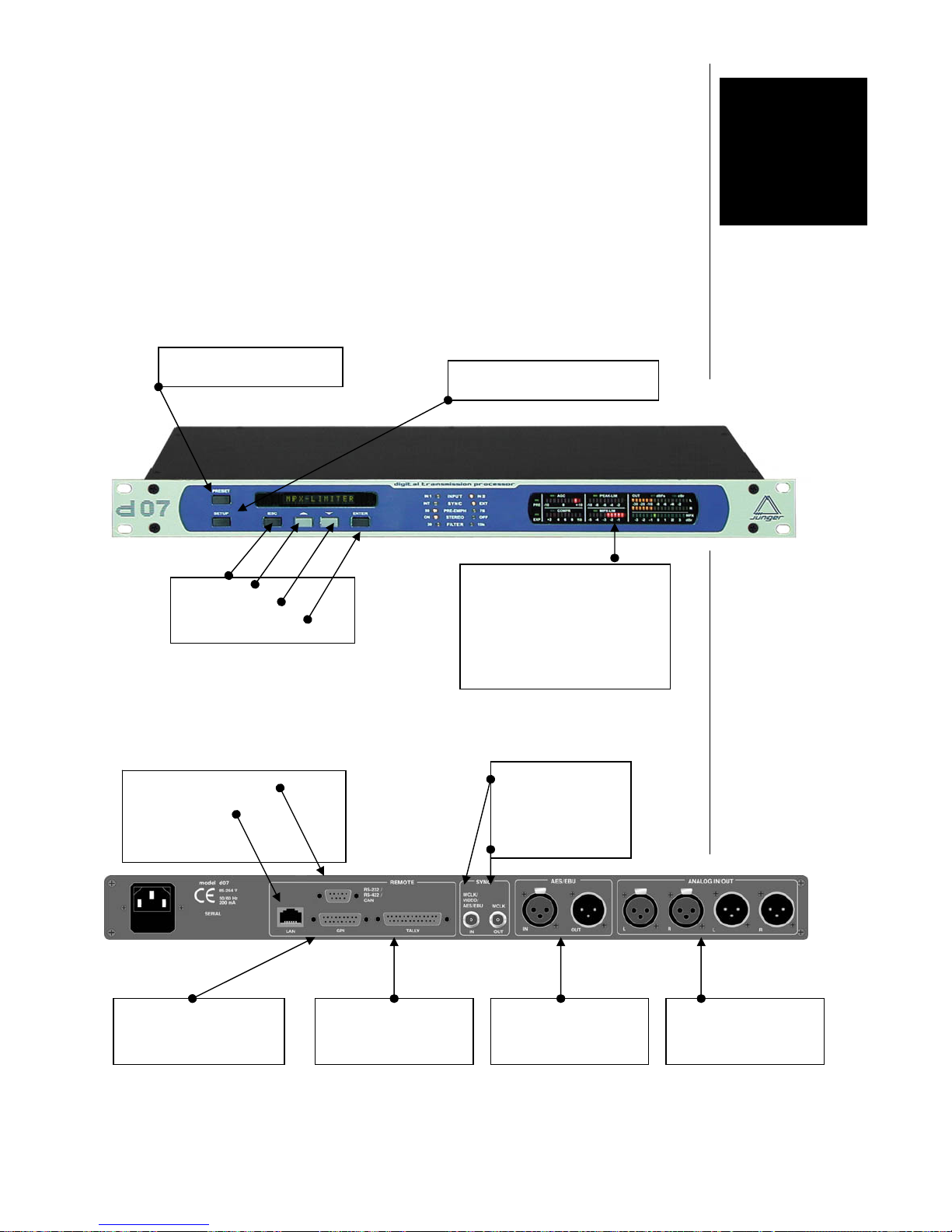
PRESET switch :
Load / save / edit presets
SETUP switch :
Configuration / parameter editing
Status display :
AGC (gain change of Leveller:
AGC+transient processor)
Compressor (without Level Magic)
Peak-Lim
MPX-Lim
Output-Level
MPX-Power
3.1.
FRONT
PANNEL
3.2
REAR
PANNEL
Analog I/O
Analog level adjustment
GPI
15 pin female connector
EXTERNAL SYNC IN
Word clock
Video
AES
WORDCLOCK OUT
REMOTE INTERFACES
9 pin Female connector :
RRS 232 / CAN
RJ 45 connector :
Ethernet
Digital I/O
AES / EBU
Tally out
25 pin female
Page 16

POWER INPUT
IEC mains input connector 85-264V, 50/60 Hz with integrated fuse
REMOTE
serial remote interface RS-422 (232)
connector: 9pin SUB-D, female
GPI
parallel remote interface
TALLY-out open relais contact
connector: 25pin SUB-D, female
GPI-in +3,5…+30V potential-free
connector: 15pin SUB-D, female
SYNC
SYNC IN
input for ext. sync signal (AES 3 format, 75 Ohm, unbal)
or video sync signal (blackburst, 75 Ohm, unbal) or
wordclock sync signal, TTL level, unbal
connector: BNC socket
WCLK OUT
output for word clock (system clock of d07)
connector: BNC socket
DIGITAL IN
input for AES/EBU standard format
connector: XLR female panel jack
DIGITAL OUT
output for AES/EBU st andard format
connector: XLR male panel jack
ANALOG IN/OUT
Analog input to 24 bit A/D-converter
Input floating balanced, XLR connector female
Analog output from 24 bit D/A-converter
Output floating balanced, XLR connector m
Some basic settings can be made by switches and jumpers at the internal circuit
boards of the unit. These settings can occur general changes for operation and should
made by qualified engineering staff only.
Internal
To set any internal jumper or switches it is necessary to open the unit.
PLEASE DO NOT MAKE ANY ALTERATIONS WITH THE MAINS STILL
CONNECTED TO THE UNIT!
Loosen the screws on the top cover and remove. Then you can see all jumper and
switches as shown in the drawing below. After setting of jumper or switches
reassemble the unit in opposite order.
3.3
Switches and
Jumpers for
Configuration
Page 17
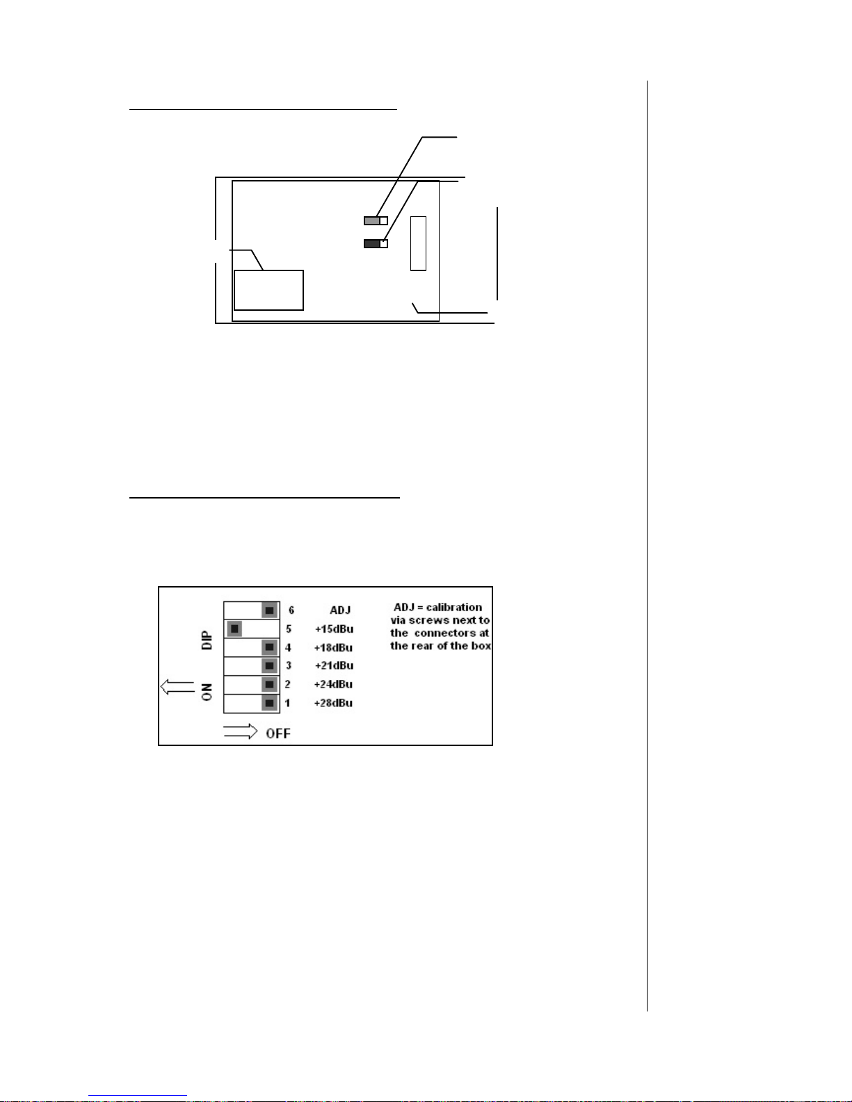
Selection of the serial remote interface
J2 – RS-232 / RS-422: Selection of the serial rem ote interface (see 3.8.3)
J3 – A / B: for factory use only, set to A
calibration of the analog in-and outputs
At our factory the d06 is calibrated German broadcast standard +15dBu = 0dBFS. If
you want to use a different referencer standard (say +24dBu = 0dBFS) you can change
the setting via dip switches on the main board of the d06.
Æ The switches are near the analog input and output hardware on the PCB.
With factory setting of +15dBu=0bBFS the dip switch “+15dBu” will be turned ON.
To change the setting to another standard you just have to slide this dip switch to
the right (OFF) and slide the needed dip switch that corresponds to the referen ce
standard you are using to the left (ON).
Æ Make sure that there is always just ONE dip switch turned ON!
Exception: They may all be OFF if you are using a CUSTOM reference level
CUSTOM Refernce Level (using Switch 6 ADJ)
If none of these stansard reference settings correspond to your needs you can set
the refernce to a CUSTOM level by adjusting the input sensitivity by the two
potentiometers (L and R) next to the analog input and output connectors at the rear
of the box.
Æ This should only be done by experienced engineers with measuring instruments!
Main board
J2
232/422
D06/07
J3
A
/B
DSP card
Page 18

To set the reference level manually, follow these steps:
1. Set all dip switches to “OFF” except #6, ADJ. –set it to ON
2. Adjust the potentiometers to the desried CUSTOM reference (setting). For this you
need to feed the analog input with a known refernce level and measure the digital output.
Make sure that the DSP processing is bypassed, otherwise there could be DSP gain
active!
3. When the adjustments are complete, ‘capture’ the custom settings by setting dip switch
#6 to OFF.
Otherwise your reference level could be changed by accident at the potentiometers.
rear of the box. This should only be done by experienced engineers
with measuring instruments! After having adjusted the input level bring
the dip switch back to the “OFF” position.
Page 19
A 4.1. – Front Panel Operation
Operation
The d07 transmission processor is very easy to use.
You can do all settings with the keys on the front of the device, via
remote or software.
The d07 uses two groups of data, in the CONFIG area to set up
device functions (selection of an input, synchronization or input of a
device name) and in the PARAMETER area to control the signal
processing (setting up processing parameters, MPX-limiter, etc.).
SETUP
directs to the set up menus. Here one can select between
CONFIG for device related settings and PARAMETER for signal
processing settings.
PRESET
directs to loading, saving and editing of one of the user
PRESETs.
All current data is kept in a non volatile memory. Therefore they are
immediately available when turning on the device. All changes to a
parameter are effective immediately. Pressing
ENTER
will approve it.
By pressing
ESC
the changes will be rejected and the display
returns to the parameter menu.
Loading of a PRESET will immediately carry over the values into the
operating memory. By clicking free cross fade they will be effective
immediately.
There is the possibility to edit and store PRESETs in the back ground,
without taking them over into the operating memory to prepare the
device for a different kind of program that is awaited.
NAVIGATION through menus of the d07 is done by the
ENTER ESC
keys :
ENTER
- directs into the next possible navigation level
- exit settings
- stores altered values
- directs back to the previous navigation level
ESC
- abort (changes are rejected)
- back to the previous navigation level
- scrolling through the navigation level
and - switching status like ON or OFF
- altering of values
A 4
4.1 FRONT PANEL
OPERATION
Function of the
d07 keys
4.1.1.
NAVIGATION
Page 20
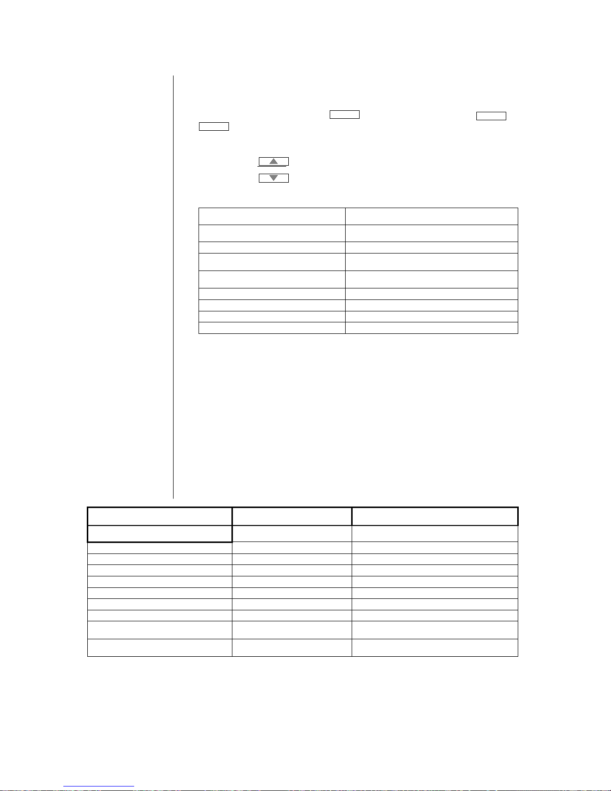
A 4.1 – Front Panel Operation
When you switch on the d07 the main display will show you the current
controller software and hardware version of your device. You can always
have a look on it by pressing
ENTER
if you are not in a menu (
SETUP
or
PRESET
).
After a few seconds the main display switches to showing the input level
(R/L).
By pressing you can step through the following status details:
Display
Description
MAIN DISPLAY
D07 C:xx D:yy
Device, Controller software, DSP version
L: xxx R: xxx
Input Level channel L/R in DBFS/dBr (CONFIG
out meter)
D07 DEVICE
Device name, 16 characters possible(CONFIG
device name)
PRESET x: yyyy
Shows current preset
MPX-POWER -14.9dB
Shows actual MPX-Power of the output signal
AGC 0.0 dB
Instantaneous value of the AGC gain
BAL R: 0.0dB
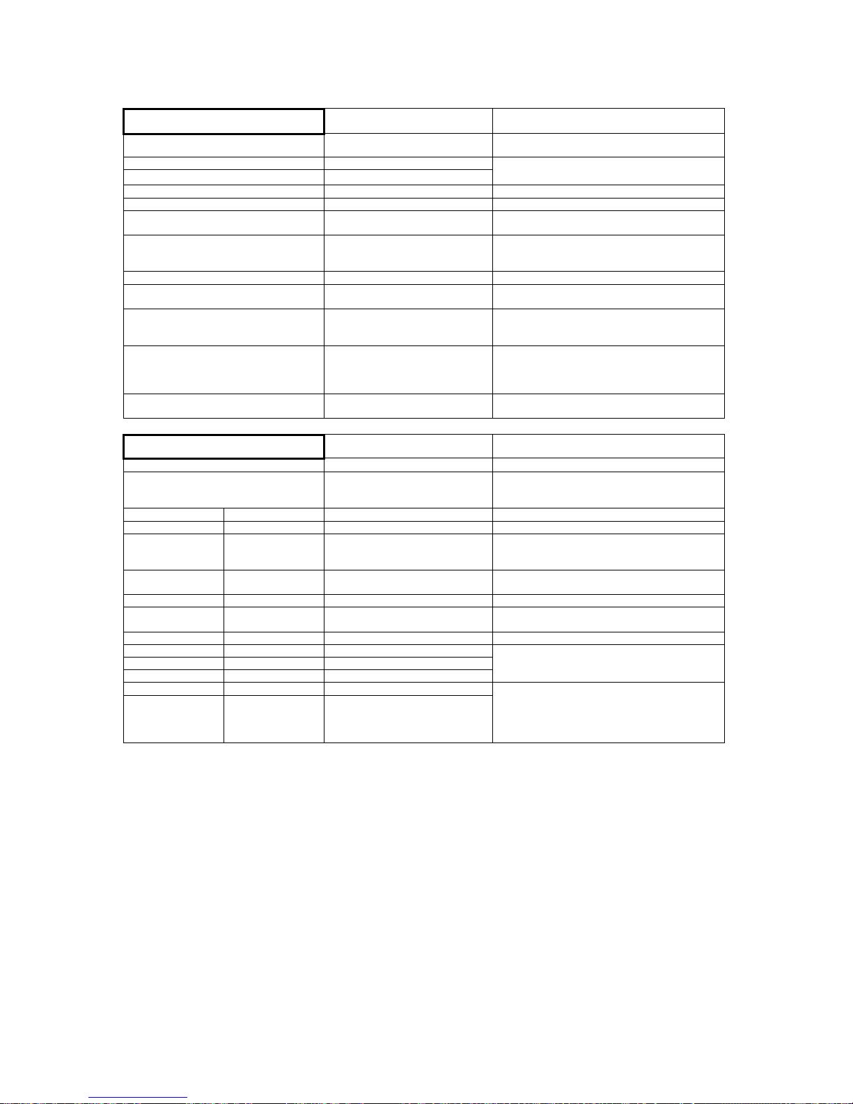
The chart on the following pages gives an overview over the menu structure,
its parameters and the available ranges:
Menu item
Value/range Description
PRESET
*
LOAD PRESET Preset 1-4 User presets
TV U TV universal
R U Radio universal
R SP Radio Sports
TV L TV live
TV M TV movie
R CL Radio classic
EDIT PRESET Preset 1-4 Here you can change the settings of your
individual presets
SAVE PRESET Preset 1-4 Here you can save your individual preset in
one of 4 available user presets
* When you switch on your d07 or initialize it, the “initialize” preset is loaded.
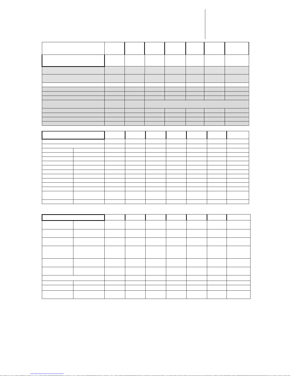
Before you start checking the parameters of the d07 you should load one of the factory presets.
Choose the one most fitting to the genre of your program (see list below).
4.1.2.
MAIN DISPLAY
4.1.3.
MENU
Preset / Setup
Page 21
A 4.1 – Front Panel Operation
SETUP
CONFIG
INPUT INPUT 1: analog
INPUT 2: digital
Select the input mode according to your
input signal (analog/digital AES/EBU)
LEVEL MAGIC OFF/ON switch Level Magic off/on
PASSWORD 1 2 3 4 (factory preset) Set your own password to lock the device
LOCK OFF/ON
Device can be protected against accidental
changes while transmission operation
OUT METER dBFS/dBr
Select between the display of relative
output level in dBr to the setup value of the
limiter or absolute value in dBFS
DEVICE NAME 16 characters possible Set your individual device name
CAN ID 00-99
Device address for the CAN-bus for the
remote control (optional)
TALLY 1-8
off, preset 1-4, stereo, Exp,
Compr, Lim, Preemp, Clip,
Input2, Bypass
8 TALLY outputs are carried out as relay
change –over switches. One of 12 states of
the d07 can be allocated to them
GPI 1-8
off, preset 1-4, stereo, Input2,
Bypass
GPI input are carried out as opto coupler
driven by a current source. One of seven
predefined states of the d07 can be remote
controlled by them
SYNC
Video, Wclk,Ext AES, Input AES,
INT 44.1, INT 48
Selection of the SYNC source
PARAMETER
GAIN -20 to +20dB Setting the initial gain
STEREO OFF/ON For stereo operation with the d07 the
control circuits of the dynamic sections can
be linked
FILTER 30Hz OFF/ON Switching off/on 30Hz low cut filter
15kHz OFF/ON Switching off/on 15kHz-FIR-Filter
PREEMPHASIS PRE MODE OFF/50µs/75µ The d07 controls high frequency signal
components to adapt the audio signal to
the predefined pre-emphasis.
PRE THRES
Setting has to be equal/bigger than the
Limiter Thresh (see B 5.3)
PEAK-LIMITER LIM THRESH determines the max output level of the d07
LIM PROG Pop, speech, uni, live, classic Characteristic of the LIMITER can be
adapted to the program material
MPX-LIMITER MPX-POWER OFF/ -4 to +4dB Limits the power of the MPX-signal
EXPANDER EXP THRESH OFF/-20 to -60dBFS
EXP RANGE OFF/-0 to -20dBFS
EXP ATTACK 0,2 to 4sec
Levels lower than EXP TRESH will be
lowered => Enhancement of S/N ratio,
active after AGC
AUTO-BALANCE BAL RANGE 0 to 20dB
BAL TIME 1,2,5,10,20,40sec/min, 1h, 2h
In stereo mode the balance between the
two channels can be controlled
automatically (reference: left channel), e.g.
valuable if there are level changes on the
transmission path
Page 22

A 4.1 – Front Panel Operation
LEVEL MAGIC ON
LEVELLER
OPERATING
LEVEL
-40…0dBFS
Desired target level for the levelling process.
Reference Level for the Transient Processor
and Leveller
TR P RANGE 0…15dB
Determines the maximum gain change applied
by the Transient Processor when there are fast
input level changes. Large range values are
reducing the dynamic range, especially in
combination with the transient program “hard”
TP PROG soft/mid/hard
This parameter describes the characteristic of
gain change by the transient processor. It has
to be chosen dependent on your program
genre. If there are just a few level changes or
you want to keep the original dynamic range
best (e.g. classical music), you have to choose
“soft”. For mixed program “mid” should be best
in most cases. And for live venues (sport etc.)
with frequent unexpected level changes the
adjustment “hard” is required.
SILENCE GATE
= AGC gate
-60… -20dBFS
If the input level falls below this threshold level,
the gain change of the AGC freezes
immediately (transient processor still active).
After appr. 20 seconds input level below
silence gate the current gain change is slowly
moving to the longterm average gain.
LEV TIME
= AGC time
10s…2h
Describes the time of development for the
AGC to reach the maximum possible gain
change (range value).
The ratio of gain change should never be
faster then 3 seconds for 1 dB!! We are
recommending a setting of 4…5 seconds for
1dB gain change by the AGC. Therefore the
AGC time is basically determined by the AGC
range value. A range setting of 10 dB requires
a time setting of minimum 40 seconds.
LEV RANGE
= AGC range
0…40dB
Determines the maximum gain change applied
by the AGC.
AGC Range must be bigger then the expected
difference between the average input level and
the operating level.
If there is for example an average input level of
-23dBFS and your OP-Level is -18dBFS, the
AGC needs at least a range of 5dB. In most
cases an AGC range of 10dB is a good choice
LEVEL MAGIC OFF
COMPR COMPR RATIO OFF/ 1.1 to 4.0
COMPR PROG
live, pop, speech, uni, classic
COMPR
RANGE
0 to 20dB
Compresses the audio signal => increase
of loudness, complicated settings are not
necessary because there are diverse
adaptive control algorithms, which can be
accommodated in an optimal way with the
parameter COPM program
Page 23
A 4.1 – Front Panel Operation
Initiali
ze
preset
P5
TV uni
P6
radio
uni
P8
Radio
speech
P8
TV
live
P9
TV
Movie
P10
Radio
classic
SETUP
CONFIG
INPUT
analo
g
LEVEL MAGIC on on on on on on on
PASSWORD 1234
LOCK off
OUT METER dBFS
DEVICE NAME
device
d07
Grey marked parameters are not sav ed in the preset!!!
CAN ID 00
TALLY 1-8 off
GPI 1-8 off
SYNC INT 48
PARAMETER
GAIN 0.0 0.0 0.0 0.0 0.0 0.0 0.0
STEREO off on on off off on on
FILTER 30Hz off on on on on on on
15kHz off on on on on on on
PREEMPHASIS PRE MODE off off off off off off off
PRE THRES 0.0 0.0 0.0 0.0 0.0 0.0 0.0
PEAK-LIMITER LIM THRESH 0.0 -9.0 0.0 0.0 -9.0 -9.0 0.0
LIM PROG uni uni uni speech live uni classic
MPX-LIMITER MPX-POWER off off off off off off off
EXPANDER EXP THRESH off off off off off off off
EXP RANGE off off off off off off off
EXP ATTACK 0.5 0.5 0.5 0.5 0.5 0.5 0.5
AUTOBALANCE
BAL RANGE
0.0 0.0 0.0 0.0 0.0 0.0 0.0
BAL TIME 1min 1min 1min 1min 1min 1min 1min
LEVEL MAGIC ON
LEVELLER
OPERATING
LEVEL
0 -18 -9 -9 -18 -18 -9
TR P RANGE
0 10 10 15 10 6 3
TP PROG
Soft Mid Mid Hard Hard Mid Soft
SILENCE
GATE
= AGC gate
-40 -50 -50 -40 -50 -50 -60
LEV TIME
= AGC time
1 min 40sec 40sec 20sec 20sec 2min 2min
LEV RANGE
= AGC range
0 10dB 10dB 10dB 10dB 15dB 10dB
LEVEL MAGIC OFF
COMPR COMPR RATIO
COMPR PROG
COMPR
RANGE
4.1.4.
FACTORY
PRESETS
Page 24
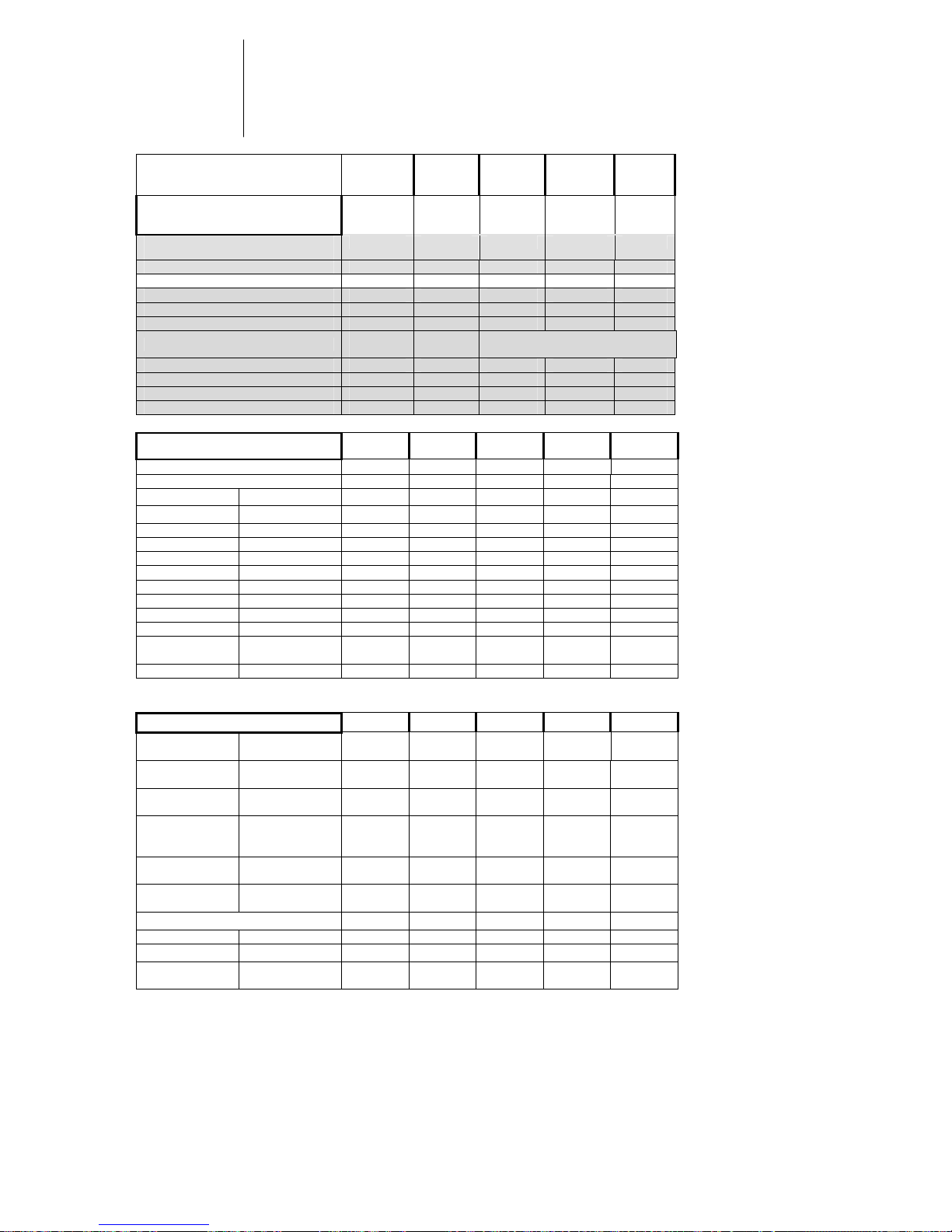
A 4.1 – Front Panel Operation
Initializ
e
preset
P1 P2 P3 P4
SETUP
CONFIG
INPUT analog
LEVEL MAGIC on on on on on
PASSWORD 1234
LOCK off
OUT METER dBFS
DEVICE NAME
Device
d07
grey marked parameters are
not saved in the preset!!!
CAN ID 00
TALLY 1-8 off
GPI 1-8 off
SYNC INT 48
PARAMETER
GAIN 0.0
STEREO off
FILTER
30Hz
off
15kHz
off
PREEMPHASIS PRE MODE off
PRE THRES 0.0
PEAK-LIMITER LIM THRESH 0.0
LIM PROG uni
MPX-LIMITER MPX-POWER off
EXPANDER EXP THRESH off
EXP RANGE off
EXP ATTACK 0.5
AUTOBALANCE
BAL RANGE
0.0
BAL TIME 1min
LEVEL MAGIC ON
LEVELLER
OPERATING
LEVEL
0
TR P RANGE
0
TP PROG
Soft
SILENCE
GATE
= AGC gate
-40
LEV TIME
= AGC time
1 min
LEV RANGE
= AGC range
0
LEVEL MAGIC OFF
COMPR COMPR RATIO
COMPR PROG
COMPR
RANGE
4.1.5.
User
PRESETS
Page 25
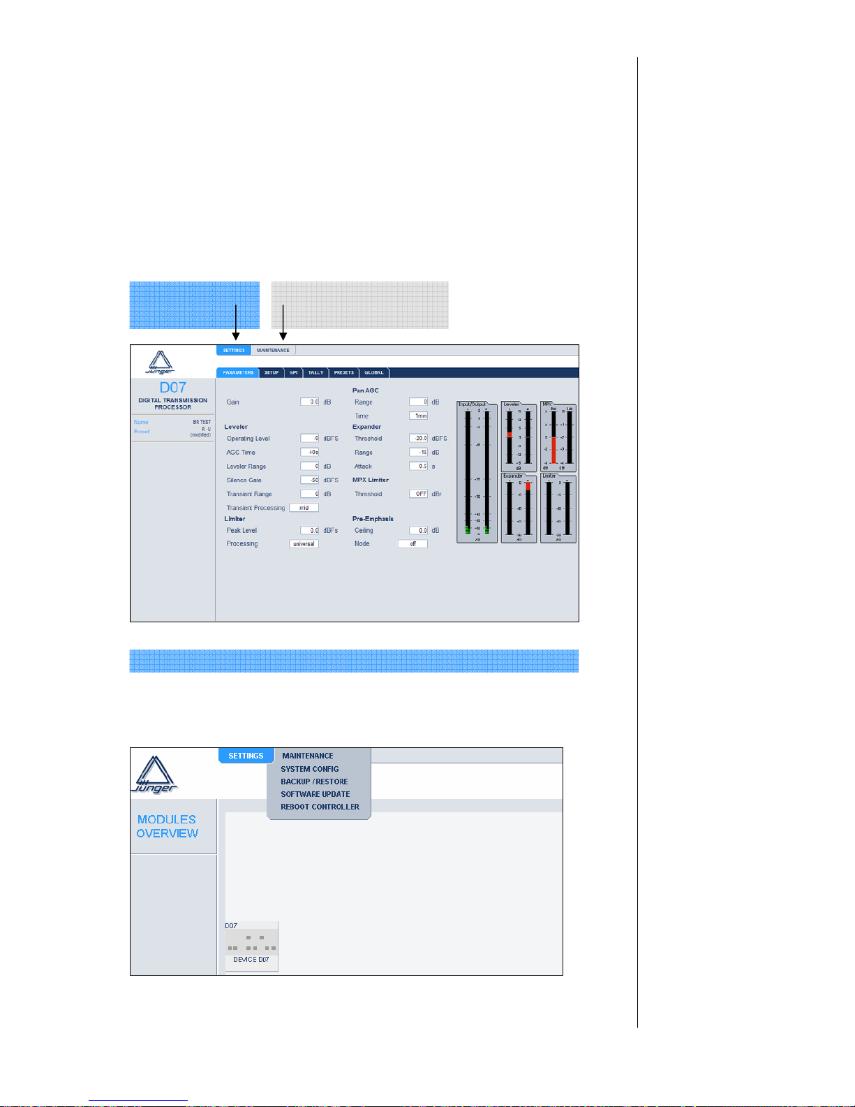
A 4.2. – operation via web browser
4.2.1. Web interface of the d07
After the configuration of network and IP-address of your device you can operate
the d07 easily via web browser. (See chapter B6 Network integration)
Just type the valid IP-address of your device into your web browser
(http:// IP-address).
You will get the following page:
4.2.2. Maintenance
Device
related settings
web interface controller
related settings
4.2 Operation
via web browser
Device related settings / Parameters of the device are described in 4.1.3.
Page 26

A 4.2 – operation via web browser
System configuration
Change network configuration:
IP-address, netmask, gateway
Only possible when your network configuration is adjusted to the
preconfiguration of the device, see “NETWORK INTEGRATION”
Back up / restore
Using the backup function a whole d07-data set (setup and parameters) can be saved
as a html-file into a folder of your choice. You can use this file to restore all the
parameters of your device at a later date or to load this data set into another device.
Software update
To update the software of the web interface controller you just have to load the
update-image and press “update”. The image does also contain contingent updates
for the controller of the device. This update will be automatically offered when you go
to the “GLOBAL” page of the d07 module.
Reboot controller
Rebooting the device activates the changes you have made to the network
configuration. If you have changed the IP address of the device, you are not able to
reach the web interface after the reboot. You have to use the new address, of course!
4.2.3. DATA transfer
All changes you make at the web browser interface are
immediately transmitted to the device.
If you make any changes at the front panel of the d07 you
have to refresh the web browser page to get the data
transferred. Only a preset load is reported directly to the web
interface. The change of a preset name is only transmitted by
refresh.
Web browser d07
immediately transmitted
and executed
immediatel
y
executed
transmitted by refreshing the
web site
d07 Web browser
Page 27

A 5 -Boot display and trouble shooting
BOOT DISPLAY AND
TROUBLE SHOOTING
display meaning / explanation
JUENGER
AUDIO D07
display of model
C: x.x display of loaded controller software version
D: x.x display of loaded dsp software version
display error / message remedies
SYNC
ERROR!
no sync at sync input! connect the sync input
(selectable in SYNC field) with
valid input signal
¾ INPUT: sync on DIGITAL IN
CH 1/2
¾ EXT AES: sync on SYNC
AES/EBU
¾ EXT VIDEO: sync on SYNC
VIDEO
¾ EXT WCLK: sync on word
clock
5.1
BOOT DISPLAY
5.2
ERROR
MESSAGES AND
TROUBLE
SHOOTING
A 5
Page 28

A 5 -Boot display and trouble shooting
Should have remained the device no more operable and/or in the program
execution stand, recommends itself an initialization the device.
During initialization, all storage areas and registers important for the program
are loaded with the factory setup and the program is restarted.
Any button (exceptional >>MENU, Peak up>>) is to be held pressed in order
to initialize the device during power-on of the device until the program has
started. To the start of the program and at the completion of the displays (how
described in 6.1), the device is ready for operation with the factory setup.
After an initialization of the device, all user presets and adjustments are
erased and/or overwritten by the factory setup!
5.3
INITIALIZATION
THE UNIT
Page 29

A6 -Technical specifications
TECHNICAL
SPECIFICATIONS
sample rate 44.1/48 kHz
audio data format 24 bit
DIGITAL IN/OUT
AES/EBU
connector XLR, 110 balanced
input format AES professional, AES consumer
output format same as input format
channel status bits:
digital input -> digital output transparent
analog input -> digital output fixed channel status bits
(professional/48kHz sample
frequency/2ch mode/24 bit audio)
ANALOG IN/OUT
ANALOG IN
Resolution 24bit
sample rate 44.1…48kHz
dynamic range 110dB (RMS)
114dB (A-weighted)
THD+N <0.002% @ max. input level
frequency response 20Hz...20kHz (FS=48kHz) (+/-0.5dB)
CMRR –100dB @ 50Hz
max. input level +22dBu @ 0dBFS
input impedance 10 kOhm, floating balanced
connector XLR, 1-screen, 2-live, 3-return
ANALOG OUT
Resolution 24bit
sample rate 44.1…48kHz
dynamic range 108dB (RMS)
110dB (A-weighted)
THD+N <0.002% @ max. input level
frequency response 20Hz...20kHz (FS=48kHz) (+/-0.5dB)
max. output level +22dBu @ 0dBFS
output impedance 30 Ohm, floating balanced
connector XLR, 1-screen, 2-live, 3-return
digital signal
processing
digital
in- / outputs
analog
in- / outputs
A 6
Page 30

A6-Technical specifications
SYNC IN
WCLK connector BNC, 75Ohm, coaxial
level TTL-level
input format Wordclock
AES/EBU connector BNC, 75 Ohm, coaxial
level 0,5 ... 5 Vpp
input format AES professional, AES consumer
VIDEO connector BNC, 75 Ohm, coaxial
level 0...1 Vpp
input format Blackburst or PAL/NTSC composite video
WCLK OUT
WCLK connector BNC, 10kOhm, coaxial
level TTL-level
output format Wordclock
REMOTE
serial remote interface RS-232 in/out
connector 9 pin SUB-D female
serial remote interface RS-422
connector 9 pin SUB-D male, optional TCP/IP
GPI parallel remote
level opto coupler, 3..24V control voltage
connector 15 pin SUB-D female
Tally Out
level relais contact
connector 25 pin SUB-D female
power consumption appr. 15 VA
dimensions 19“, 1 RU, 250 mm depth
weight appr. 5 kg
sync
in- / outputs
remote control
general
Page 31

B – APPLICATION NOTES
B – APPLICATION NOTES
1. The Junger Audio Dynamics Processor Principle
2. The Junger Audio Compressor & Expander Principle
3. The Junger Audio Processing Presets
4. LEVEL MAGIC
5. GUI
6. Network Configuration for TCP/IP Operation
7. FM-Transmission (d07)
7.1. General
7.2. MPX-Limiter
7.3. Pre-emphasis
7.4. terms and definitions
B
Page 32

Page 33

B1 – The Junger Audio Dynamics Processor Principle
THE JUNGER AUDIO DYNAM ICS
PROCESSOR PRINCIPLES
Changing the dynamic range of an audio signal is inherently a non-linear process.
Unlike an ordinary line amp, the gain of a dynamic range processor is not constant
– it varies with time depending on the specific control algorithm of the dynamics
processor and the changing amplitude of the input signal. These variations in the
gain, which represent the real control process, should take place without any
bothersome side effects to the audio signal itself, effects such as pumping, signal
distortion, sound coloration, or noise modulation. In other words, they should be
inaudible.
The setting of the attack time parameter of a dynamics element effects how the
unit will react to rapid amplitude changes in the audio signal. A long attack time
leads to overshoots (and consequent distortion) because the system is not fast
enough to reduce the gain. A short attack time minimizes the chance of
overshoots, but the more rapid gain changes in such cases have audible side
effects such as "clicks" and other modulation artifacts.
Traditional Compressor and Limiter Designs
Traditional compressor and limiter designs only have one control circuit with one
attack time and one release time. They must be adjusted manually by the user to
optimal settings for processing with as little disturbance as possible through a
process of trial and error. A lot of experience and a lot of time is necessary to get
acceptable results. These settings, once found, are only the right choice for a
certain program signal and must be changed for other program types.
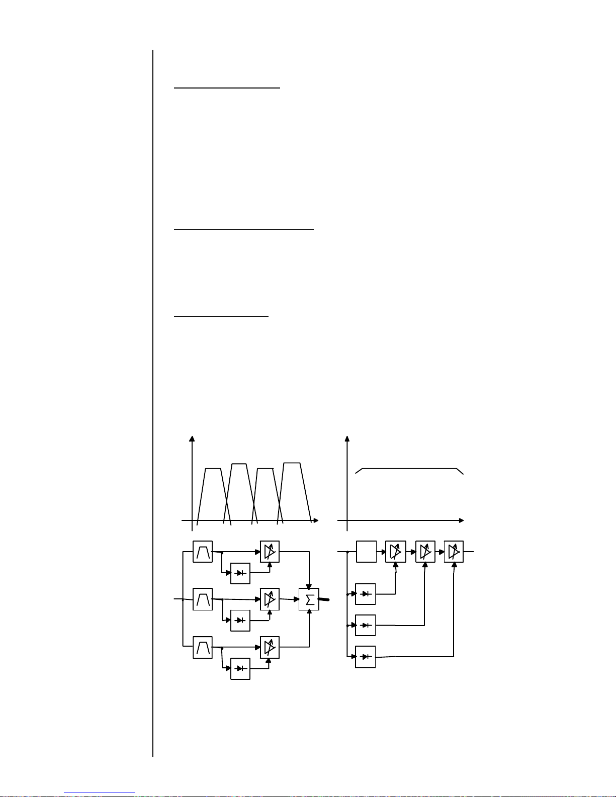
Multi-band designs
These units split the audio frequency spectrum into several frequency bands. The
attack and release times are set independently for each frequency band, giving
independent processing for each band. The problem with this multi-band approach
comes when the outputs of each band’s processor are combined together to
produce the output audio. The spectral balance of this output signal is always
different from the input. The balance of high, mid, and low frequencies is inherently
disrupted, which is particularly objectionable when the signals are music, as in
commercials, concerts, etc.
Multi-Loop designs
The Junger Audio Dynamics Processors work according to a Multi-loop principle.
The various loops each work over the entire frequency spectrum. They work in
parallel, each with a different set of attack and release parameters. Each loop
develops a control signal which is then summed with the controls from the other
loops to produce a single gain control signal applied to one gain control element.
Please see the figure below.
B 1
Page 34
B1 – The Junger Audio Dynamics Processor Principle
Look Ahead/Signal Delay
The digital implementation of the Junger Multi-loop design also permits a very short
time delay (approx. 2ms) to be introduced in the audio signal path. It lets the gain
changing elements “look ahead” and determine the correction needed. This is applied
to the delayed signal just in time to control even the fastest transients. That is
particularly important for the limiter, which provides a precisely levelled output signal
absolutely free of overshoots (clipping).
When mixing together a delayed signal and a direct signal there may be cancellation
of the signal waveform at some frequencies and re-inforcement of the waveform at
other frequencies (comb filter effect). Corresponding 2ms delay of direct signals
should therefore be carried out before mixing them with delayed processed signals.
Adaptive Dynamic Range Control
The proprietary algorithms in the Junger System also allow the automatic adjustment
of the attack and release times according to the evolution of the input signal over time.
This is called Adaptive Dynamic Range Control. By monitoring the waveform of the
incoming audio, the System can set relatively long attack times during steady-state
signal conditions but very short attack times when there are impulsive transients.
The Best Performance
The dynamic range processor principles developed by Junger Audio make it possible
to realize dynamics processors (compressor, limiter, expander) with very high audio
quality, without signal coloration, pumping or breathing, and without distortion and
modulation products.
In short, they offer the best possible performance – inaudible dynamics control.
A A
f
delay
1
1
2
2
n
m
f
Multi - Band Multi - Loop
Page 35
B 2: The Jünger Audio Compresor & Expander Principle
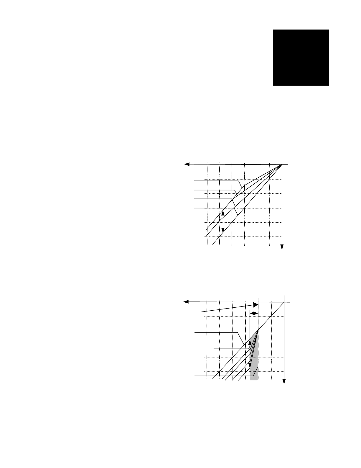
Figure 1: Compressor characteristics
Figure 2 Expander characteristics
THE JÜNGER AUDIO COMPRESSOR &
EXPANDER PRINCIPLE
Compression is defined as the reduction of the dynamic range of the input signal
to match the dynamic range of the storage system, transmission system, and/or
the listening environment. Typical approaches to this task often result in audible
artifacts and lack luster performance. The Jünger approach takes an atypical
approach that avoids these difficulties.
In the Jünger system, compression of the program signal takes place over the
entire input level range, not just the upper end above a certain threshold level.
Compression is partly achieved by
increasing the level of low level signals.
The lower the input signal level, the
higher the additional gain applied to that
input signal by the compressor. As the
level of the input signal rises, the amount
of gain applied is reduced. Please see
the figure to the right.
Dynamic structures of the entire range of
the input signal amplitude are converted
proportionally. Even after compression
the dynamics of incoming audio are
maintained, only slightly condensed,
leaving a transparent, seemingly
uncompressed sound impression.
The gain of the compressor (called
‘range’) can be limited from 1 dB to 15dB
to prevent unacceptable increase in
back grounds during signal pauses
(e.g. ambience).
To help eliminate unwanted very low
level noise (air-conditioning, hum, and
noise), a Jünger Expander can be used.
Below an adjustable threshold level, the
expander will attenuate the level of the
incoming signal: as the incoming signal
drops so low that it is ‘in the noise‘ the
Expander reduces the signal level further
to ‘hide‘ the noise.
The Range parameter sets the maximum
attenuation applied when the incoming
signal level is within 6dB below the
Threshold level.
B 2
2.0:1
1.6:1
1.3:1
OFF
ratio
-50
-40
-30
-20
-10
[dBFS
]
-10-20-30-40-50-60
output
input
range
max. 15d
B
gate
OFF
6dB
-50
-40
-30
-20
-10
[dBFS]-10-20-30-40-50-60
output
input
range
0...40 dB
threshold
level
-20...-60, off
Page 36

Page 37

B 3 – The Junger Audio Dynamics Pocessing Presets
THE JUNGER AUDIO DYNAM ICS
PROCESSING PRESETS
For some of the control parameter it is possible to define a limited range of time
constant values which are allowed for the adaptive dynamic range algorithms.
Inside this range the time constants can be varied by the adaptive processing.
Setting the range of time constant values may be sometimes useful, to get the best
signal processing performance regarding specific program material.
Parameter related to the transient response of the control circuit are important for
distortion-free processing. These time constants are always adaptive controlled
without remarkable limitation of parameter range. This is caused by the presence
of transient pulses in almost each kind of program material. The algorithm has to
guarantee best reaction for fast increasing level of transient signals anytime even if
classical music with slow dieing out characteristic is processed. In all cases the
attack time of the limiter for very short transients is zero.
Especially the release time of the control circuit has more influence to the increase
of loudness as any other parameter. The ranging of time constants in processing
time groups reflects this fact. The range for processing time shows influence on
release time parameter mostly.
The selection of the parameter PROCESS/PROGRAMM (limiter, compressor)
changes the range of time constant values as follows:
PRO Processing Time Corresponds to Preset
--------------------------------------------------------------------------------------------- 0 2 ms to 0.2 sec
1 5 ms to 0.5 sec LIVE
2 10 ms to 0.8 sec
3 15 ms to 1.2 sec SPEECH
4 30 ms to 2.5 sec POP
5 50 ms to 3.5 sec
6 70 ms to 5.0 sec UNIVERSAL
7 100 ms to 6.0 sec
8 150 ms to 8.0 sec CLASSIC
9 250 ms to 10.0 sec
B 3
Page 38

Page 39

B 4 – LEVEL MAGIC
LEVEL MAGIC
B 4
Page 40

Page 41
LEVEL
MAGIC
1. Release 2005
Junger Audio
Berlin
Introduction &
Reference
guide
TM
Page 42
LEVEL
MAGIC
Introduction & Reference guide
d06 d07 b46 C8007 C8046
Program suppliers and broadcasters alike have long been plagued by ‘surprise’ level
changes when switching from one source to another. Not only peak levels but also
average operating levels can vary wildly from one source to another, wreaking havoc
with unattended operation.
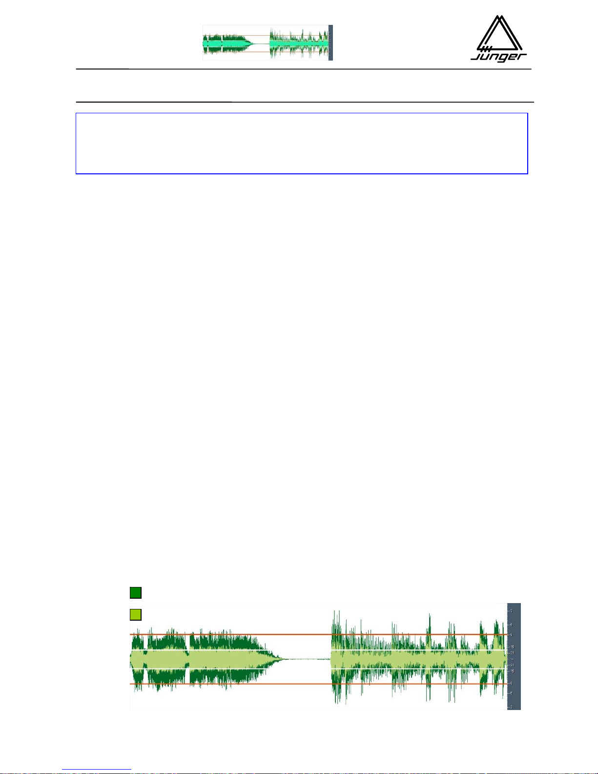
Level Magic™ from Junger Audio relies on a sophisticated new adaptive level control
algorithm capable of adjusting the right audio level from any source at any time.
Automated Gain Control + Transient Processing + Peak Limiting for continuous
unattended control of any program material.
> The audio signal is levelled to the desired Operating Level instantly!
With Level Magic™, the desired Operating Level and Peak Level are dialled in once
and thereafter, Level Magic™ will give continuous control, regardless of the source -without touching the sound of the audio material. No breathing, no pumping, no
spectral changes. Just well controlled dynamics!
> Unpleasant level jumps are eliminated
Level changes from different feeds, level differences between different program parts
or even loudness problems in broadcasting – Level Magic™ will take care of them
automatically, with a result the Listener will want to hear.
Major application fields include playout for multichannel broadcasting for satellite and
cable distribution, program transfers with audio level changes, ingest stations and any
situation where continuous control of audio level is important.
> Overmodulation is prevented by a Brickwall-Limiter
The Junger Audio brickwall limiter guarantees precise peak limiting without any
distortion. For any kind of program signal and anytime.
Input signal
Program signal processed with Level Magic ™
LEVEL MAGIC™
a sophisticated new adaptive level control algorithm capable of
adjusting the right audio level from any source at any time.
p
eak level
OP level
Page 43
Introduction & Reference guide
LEVEL
MAGIC
d06 d07 b46 C8007 C8046
Jünger Audio Studiotechnik GmbH
Justus-von-Liebig-Strasse 7
D -12489 Berlin
Germany
phone: +49 (030) 677721- 0
fax: +49 (030) 677721- 46
email: [email protected]
http://www.junger-audio.com
3/8
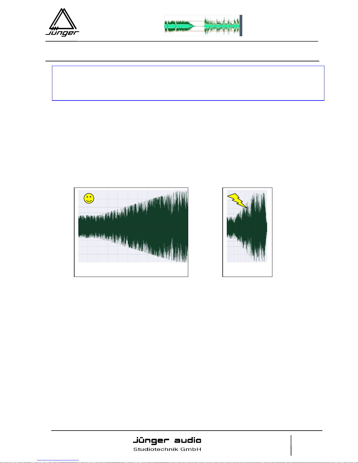
1. We do not perceive level changes if they happen in a certain period of time
dependent on the absolute value of the level change.
That means any slow level changes are not perceptable by the human ear.
That explains very clear why it is most important that AGC may not work too fast
(1dB/4-5sec)!! A fast acting AGC would cause perceptable level changes. But we are
looking to get an mostly inaudible levelling procedure.
If a fast level adjustment is required (because of transients), this is done by the
Transient Processor.
2. Level jumps rising over a certain absolute value are very unpleasant for our
ears.
Of course, it depends on the type of audio material and consequently on its loudness
which absolute value of level change really annoys. A jumping level of 6dB is
remarkable. A quick level change of 10…12dB becomes annoying for the human ear!
So it’s necessary to avoid major level changes. The transient processor of Level Magic
is a solution for that.
10dB /40 sec
10dB /10 sec
If for example the audio level rises from
-20dBFS to -10dBFS within one minute you
won’t realize it, unless the level gets over an
bearable value or the audio masks other
sources you would like to listen to.
But if the same level
change happens in 10
seconds it will be very
noticeable!
To understand the principle of the new algorithm and the adjustment of LEVEL MAGIC
it is necessary to keep some psychoacoustic aspects in mind
Page 44
LEVEL
MAGIC
Introduction & Reference guide
d06 d07 b46 C8007 C8046
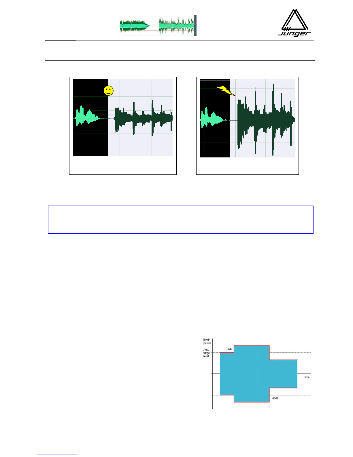
The transient processor immediately reduces or raises the level of a new program part
so that level jumps over 10…12dB are eliminated.
A compressor/limiter combination of a known dynamics processor by Junger Audio is
always controlling the audio level in relation to the limiter threshold. In result no
headroom is more existing and the signal is developed to reach a 100% output level.
This characteristic is useful to reach maximum levelling for audio disk mastering as
well as to reach 100% modulation for FM transmitters.
In compare to that Level Magic™ is serving two different levels – operating level and
peak level. Between operating and peak level we will find the so called “headroom” for
peaks that are still coming with the audio signal, even if this is level controlled related
to the operating level. Level Magic™ is a unique algorithm to make automated audio
level control possible. It is a combination of an adaptive AGC (automated gain control)
with a transient processor and a brickwall limiter. The combination of an AGC circuit
with a transient processor is the key to get a satisfying output level control for any kind
of input level changes.
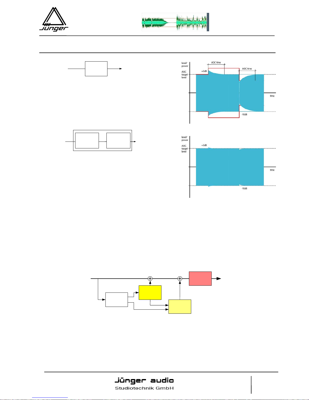
3dB level difference 9dB level difference
Input level change
The picture is showing a theoretical level change
of +5dB and –5dB around operating level.
What makes the Level Magic different from previous dynamics processors?
Page 45
Introduction & Reference guide
LEVEL
MAGIC
d06 d07 b46 C8007 C8046
Jünger Audio Studiotechnik GmbH
Justus-von-Liebig-Strasse 7
D -12489 Berlin
Germany
phone: +49 (030) 677721- 0
fax: +49 (030) 677721- 46
email: [email protected]
http://www.junger-audio.com
5/8
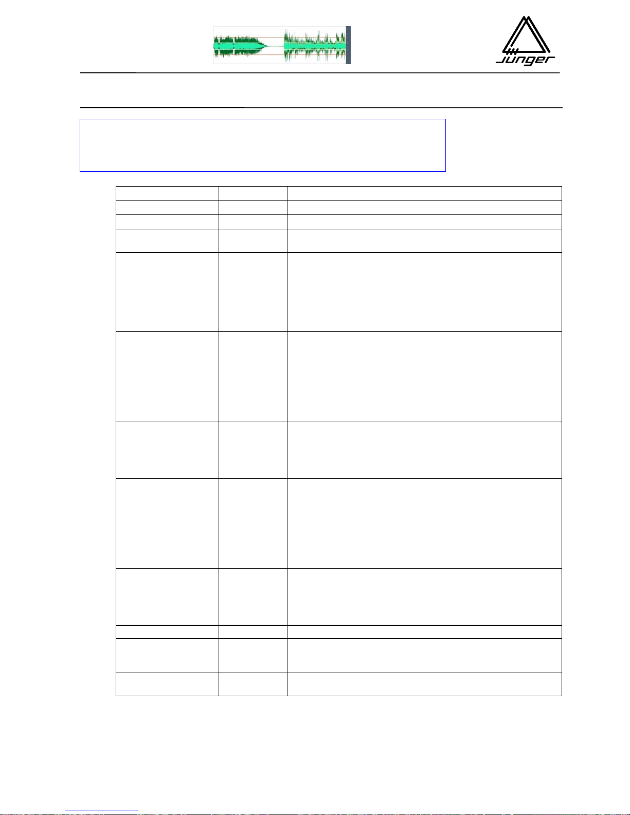
Block Diagram
Level Magic™ is consisting of adaptive AGC + Transient Processor + Brickwall limiter.
Independent on the leveller circuits the brickwall limiter is taking care on the peak level.
For the leveller (AGC + Transient Processor) Junger Audio is using a unique combination of
QP and RMS level detectors to analyze the incoming audio signal. In comparing QP and RMS
measurement results we can find out how much transients are coming in. Dependent on that
the necessary resulting gain is controlled in relation between transient processor (fast
process) and AGC (slow process).
The characteristic of the Level Magic™ level control is mostly determined by the settings of the
Transient Processor. Transient processor is doing fast gain change and the AGC is doing slow
gain change (depending on settings). Always the AGC should be set in a way that the gain
change is mostly inaudible (1dB per 5 seconds or slower). The Transient Processor should be
set that incoming level jumps are reduced but originally dynamic range is not changed too
much. As more possible gain by the Transient processor as more reduction of the dynamic
range is coming with.
Transient
Processor
AGC
Level
Detection
Limiter
Working with AGC
In this picture a conventional AGC is used to
adjust the output level. As we know the AGC
must work slow to perform a mostly inaudible
gain change. In result control on the output level
is not giving a proper correction of the input level
change.
Level Magic™
Level Magic™ is a unique combination of a
transient processor and an adaptive AGC
process. The transient processor can fill the lack
of fast level control left by the slow acting AGC.
The total gain of Level Magic™ is the addition of
the gain by the transient processor and the gain
of the AGC.
AGC
adaptive
AGC
Transient
Processor
Page 46
LEVEL
MAGIC
Introduction & Reference guide
d06 d07 b46 C8007 C8046
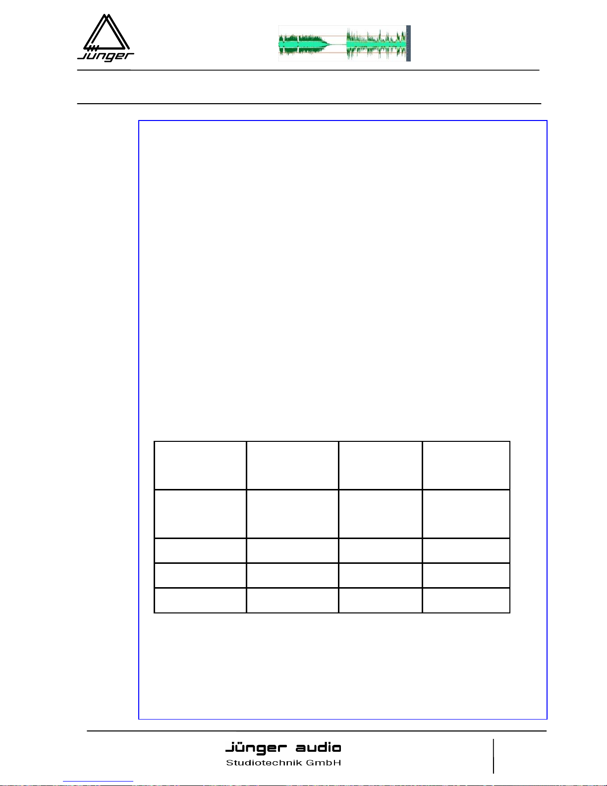
Parameter Range Description
LEVELLER
Operating Level
-40…0dBFS
Desired target level for the levelling process. Reference
Level for the Transient Processor and the AGC
AGC range
0…40dB
Determines the maximum gain change applied by the AGC.
AGC Range must be bigger then the expected difference
between the average input level and the operating level.
If there is for example an average input level of -23dBFS and
your OP-Level is -18dBFS, the AGC needs at least a range
of 5dB. In most cases an AGC range of 10dB is a good
choice
AGC time
10s…2h
Describes the time of development for the AGC to reach the
maximum possible gain change (range value).
The ratio of gain change should never be faster then 3
seconds for 1 dB!! We are recommending a setting of 4…5
seconds for 1dB gain change by the AGC. Therefore the
AGC time is basically determined by the AGC range value. A
range setting of 10 dB requires a time setting of minimum 40
seconds.
AGC gate
-60… 20dBFS
If the input level falls below this threshold level, the gain
change of the AGC freezes immediately. Transient processor
is still active. After appr. 20 seconds input level below silence
gate the current gain change is slowly moving to the longterm
average gain.
Transient
program
soft/mid/hard This parameter describes the characteristic of gain change
by the transient processor. It has to be chosen dependent on
your program genre. If there are just a few level changes or
you want to keep the original dynamic range best (e.g.
classical music), you have to choose “soft”. For mixed
program “mid” should be best in most cases. And for live
venues (sport etc.) with frequent unexpected level changes
the adjustment “hard” is required.
Transient range
0…15dB
Determines the maximum gain change applied by the
Transient Processor when there are fast input level
changes. Large range values are reducing the dynamic
range, especially in combination with the transient program
“hard”
LIMITER
Limiter Threshold
(Peak Level)
0…-20dBFS
Reference Level for the Brickwall Limiter.
The range between the Operating Level and the Peak Level
is the level headroom and should be 6…9dB.
Limiter program
0…9 Characteristic of the limiter, mostly reflecting release of the
limiter reduction. 0 – very fast, 9 – very slow.
Parameters of AGC
Transient processor
Limiter & brief description
Page 47
Introduction & Reference guide
LEVEL
MAGIC
d06 d07 b46 C8007 C8046
Jünger Audio Studiotechnik GmbH
Justus-von-Liebig-Strasse 7
D -12489 Berlin
Germany
phone: +49 (030) 677721- 0
fax: +49 (030) 677721- 46
email: [email protected]
http://www.junger-audio.com
7/8
Quick Start with Level Magic
For the first use of the Level Magic™ unit it’s advisable to start with one of the
factory presets (6 available). Some individually needed changes in the settings
can be saved later in one of the 4 user presets.
- Select the preset meeting the application you are looking for mostly.
- Check if operating level and peak level are meeting your standard. If this is
not the case readjust them and save your settings in one of the available user
presets.
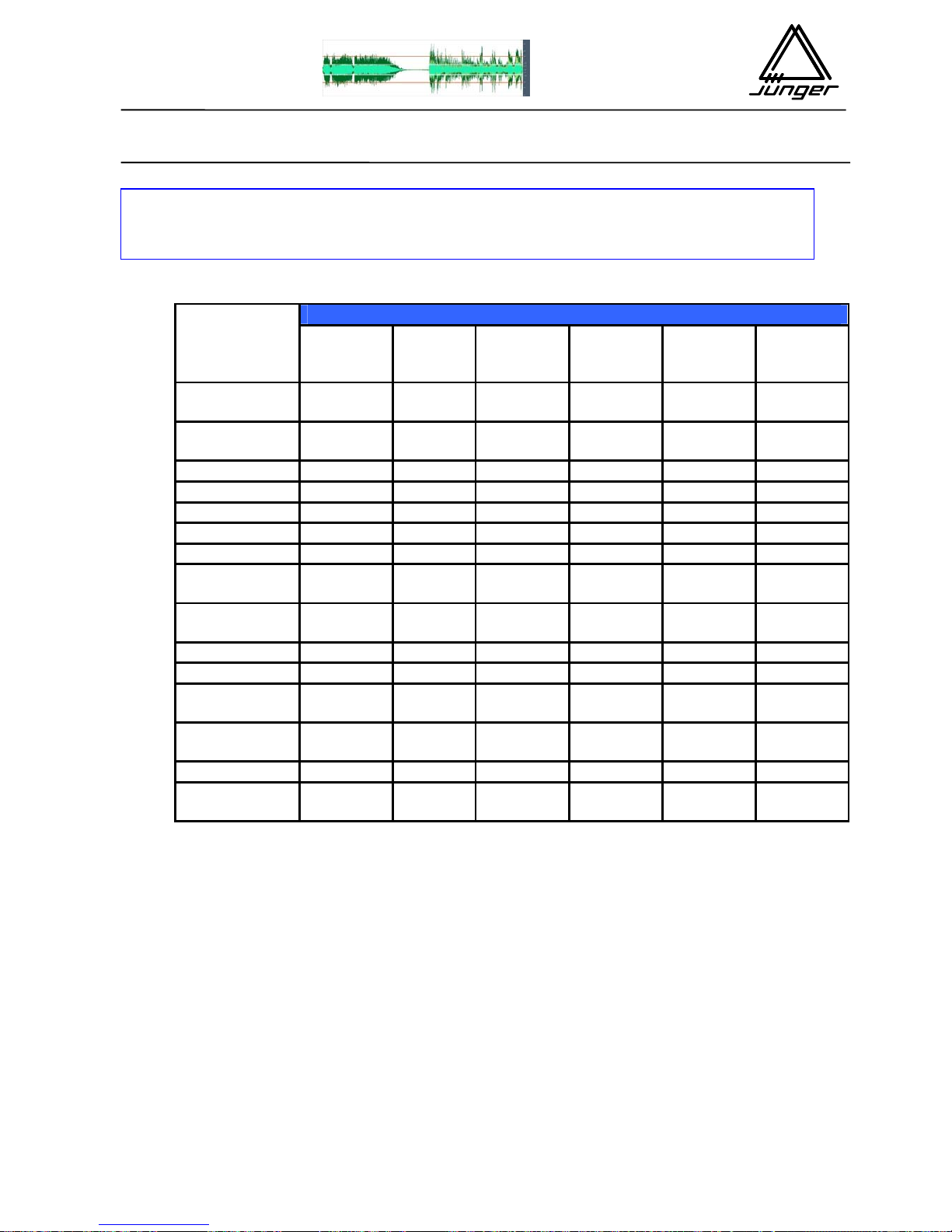
- If after having worked with different presets you think the desired setting is
between two factory presets, compare them in the following table and look for
the differences.
Always take in mind that the balance of both levelling processes is determined
the audio performance of the box mostly! As more available maximum gain by
the transient processor as more boosting the level control is. As less available
maximum gain by the transient processor as more sensible the level control will
be applied.
Because of the use of adaptive controlled processing algorithms and considering the
fact, that the AGC setting must meet the slow gain change requirement, just a few
variations are left. Mostly changeable parameters to play with are Transient
Processor Range in accordance with Transient Processor Program. The
recommendation is:
Description of the
processing result
Smooth levelling,
preserving
dramatic content
Normal
standard level
control
Boosting level
control,
decrease of
dynamic range
Content
application
Movie Sound,
Classical Music
Any kind of
audio material
Live audience,
Speech
dominated
program
Transient
Program
Soft
Mid
Hard
Transient
Range
3…5 6…8 9…12
Limiter
Program
6…8 3…5 1…2
Level Magic™ is creating the level headroom between the operating level and
the peak level. For almost any audio material used for broadcast transmission
the headroom should be 6…9dB.
With this rule it should be easy to find the settings for the limiter. Even if the operating
level is –20dBFS and therefore a technical headroom of 20dB is available it doesn’t
make sense to use it. More than 10dB headroom are increasing the dynamic range of
the audio material for broadcast transmission too much.
Page 48
LEVEL
MAGIC
Introduction & Reference guide
d06 d07 b46 C8007 C8046
Factory presets
Radio
Classical
TV
Movie
TV
Live
Radio
Speech
Radio universal
TV
universal
Parameter
LEVELLER
ON ON ON ON ON ON
OP-level
-9dBFS -18dBFS -18dBFS -9dBFS -9dBFS -18dBFS
AGC Range
10dB 15dB 10dB 10dB 10dB 10dB
AGC Gate
-60dBFS -50dBFS -50dBFS -40dBFS -50dBFS -50dBFS
AGC Time
2min 2min 20s 20s 40s 40s
Transient
Program
Soft
Mid
Hard
Hard
Mid
Mid
Transient
Range
3dB 6dB 10dB 15dB 10dB 10dB
LIMITER
ON ON ON ON ON ON
LIMITER
Threshold
0dBFS -9dBFS -9dBFS 0dBFS 0dBFS -9dBFS
LIMITER
Program
6 4 1 2 4 4
Max. total gain
change
13dB 21dB 20dB 25dB 20dB 20dB
Overview on the Factory Presets
Page 49

B 5 – GUI – software for d07
GUI – software for d07
B 5
Page 50

Page 51
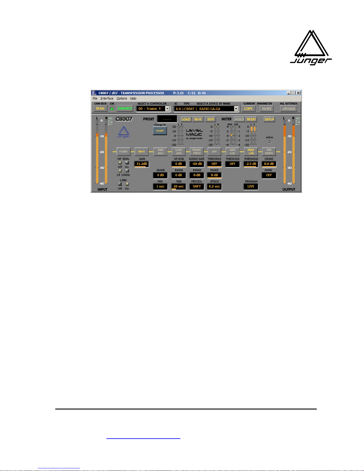
C8007control
REMOTE SOFTWARE FOR D07 / C8007
operation manuaL rel 2.0
CONTENT page
1. Introduction 1.1 Basic functions 1-1
1.2 Online remote operation 1-1
1.3 Offline editing of parameters 1-1
1.4 Data transfer
2. Software installation 2-1
3. Remote connection 3-1
4. Operation 4.1 C8007control software window 4-1
4.2 TCP/IP set up 4-1
4.3 Loading & saving files 4-3
4.4 Selecting devices 4-3
4.5 Controlling the data flow 4-5
4.6 Parameter editing 4-6
4.6.1 Function button 4-7
4.6.2 Drag label 4-7
4.7 Load presets 4-7
4.8 Save presets 4-8
4.9 Edit presets “off line” 4-8
4.10 Device set up 4-9
5. End User Licence Agreement 5-1
Justus-von-Liebig-Straße 7, 12489 Berlin, Germany
Telefon : +49-30-677721-0 Fax : +49-30-677721-46
[email protected] www.junger-audio.com
Page 52

Page 53
INTRODUCTION
page 1-1
1. INTRODUCTION
1.1 BASIC FUNCTIONS
- on-line remote control of C8007 or d07 digital transmission processors
- setting up the hardware
- storage of preset data and hardware setup data on HD
- upload of preset data from HD into the processor
- off-line editing of preset data
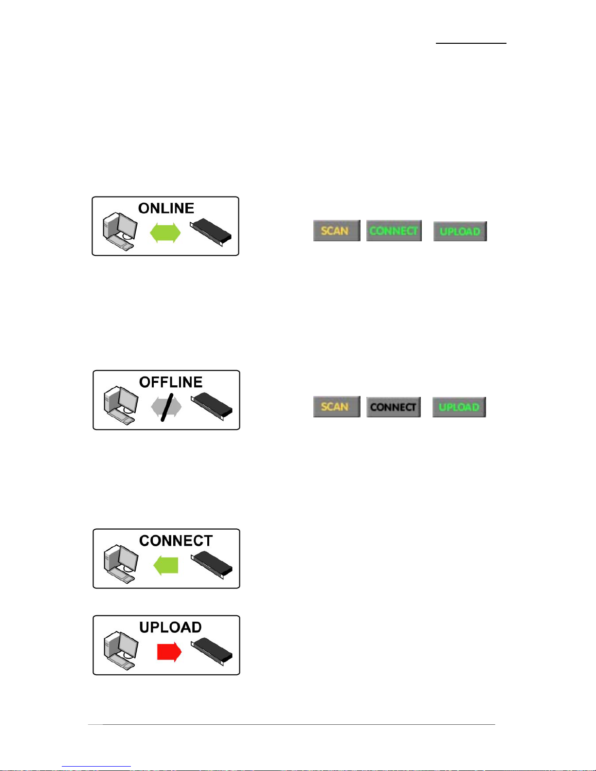
1.2 ONLINE REMOTE OPERATION
If the soft button <CONNECT> is turned on (green letters), the application is on line in other words
connected with a pre selected device. Now you will be able to :
- set the processing parameters live
- read the level meter displays and processing displays
- set the setup parameters
- edit preset data off-line in the background of the actual processing
- store preset data and hardware setup data on the PCs HD
1.3 OFFLINE EDITING OF PARAMETERS
If the soft button <CONNECT> is turned off (black letters) you are off line in other words
disconnected from a pre selected device. Now you will be able to :
- change processing parameters without effecting the actual processing
- edit setup parameters
- edit preset data
- store preset data and hardware setup data on the PCs HD
1.4 DATA TRANSFER
Connecting / reconnecting with the device will transfer all
data from the device and will overwrite the applications data.
All previously made settings in the GUI will be lost!
UPLOAD data to the device will overwrite the data of the
device. When finished it will read back the new data from the
device and will display this data in the applications GUI.
The original device data will be lost!
There is one exception: If the option “Overwrite current parameters” is not checked, the “on air”
parameters will not be changed.
Page 54

Page 55

SOFTWARE INSTALLATION
page 2-1
2. SOFTWARE INSTALLATION
SYSTEM REQUIREMENTS
Windows XP or higher
minimum screen size 1024x768
6 MB of available HDD memory
CDROM
Ethernet connection
GENERAL REMARKS
Software releases 3.xx are dedicated to the recently launched LevelMagic™ firmware of
C8007 / d07. Since many new PCs do not have serial interfaces “on board” and CAN interface
installation was sometimes tricky we decided to equip new devices with an Ethernet interface.
The C8007control software was originally developed for RS232 or CAN-bus connection. We have left
these interfaces available from the GUI but we will not support them any longer. The interface for use
is TCP/IP. This decision will also make software distribution and installation much easier because we
do not need to modify your system by special drivers (DLPORTIO.DLL / SYS).
INSTALLATION OF THE C8007control SOFTWARE
The software will be delivered on CDROM on request or will be available for download from :
www.junger-audio.com/download/software/C8007control/C8007control.zip
Use a folder of your choice and unpack the files C8007.exe and C8007_2.exe into this folder.
Or copy these files from the CDROM into such folder.
E.g. C:\program\junger\C8007control\
Read the End User Licence carefully because you will accept the licence
agreement when you install this software on a PC.
Page 56

Page 57
REMOTE CONNECTION
page 3-1
3. REMOTE CONNECTION
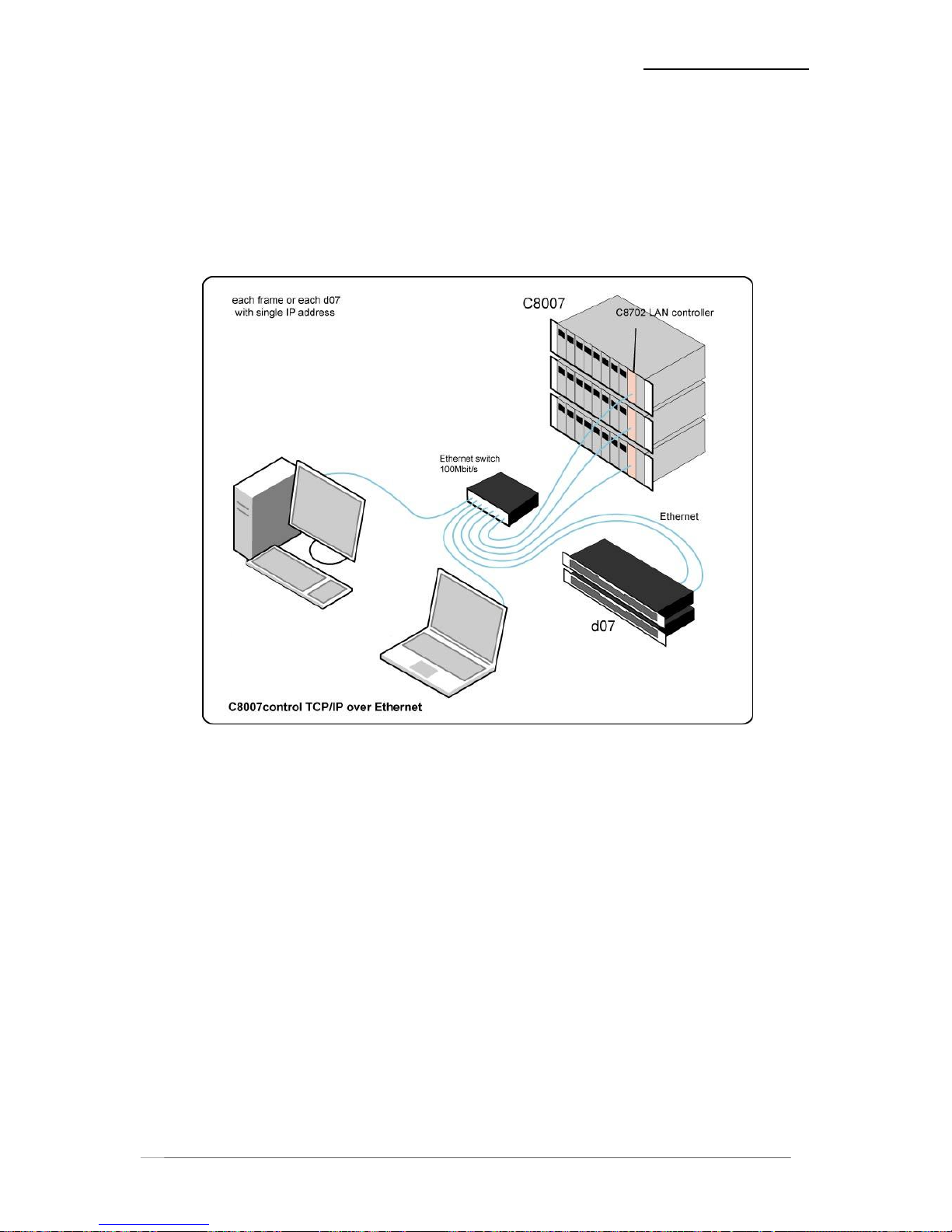
Since the introduction of the LevelMagic™ feature for d07 and C8007, all C8k systems are equipped
with a system controller C8702. The d07s have a built in Ethernet controller. So the devices must
have connection to the Local Area Network (LAN) to be available for the C8007control software that
runs on a PC (OS WXP recommended) with access to this network.
Normally you can run only one application on a PC. For special needs there is the C8007_2x.exe
that will launch two applications on a PC – the so called “double pack”.
You can run as many PCs with a C8007control application within the network as you like. The only
limitation is that only up to 3 C8007control applications can exploit one d07 device or one C8k frame
at a time.
Page 58

Page 59
OPERATION
page 4-1
4. OPERATION
4.1 C8007control SOFTWARE WINDOW
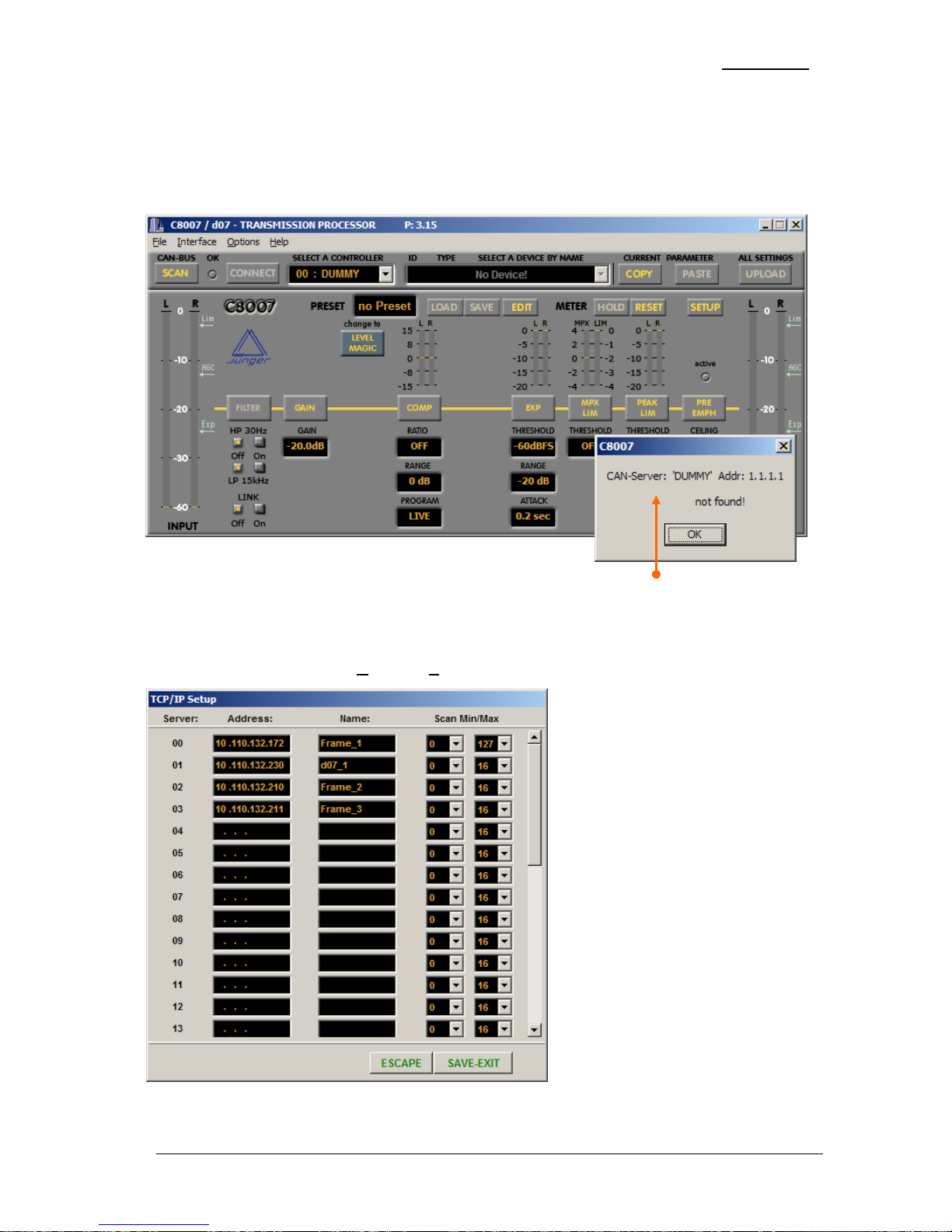
After launching the application for the first time you will see this window :
The application will try to communicate with the non existing server “DUMMY” >> press “OK”.
4.2 TCP/IP SET UP
Now you must go to the menu > O
ptions > Setup TCP/IP :
Here you can enter up to 32 different
server IP addresses.
You should overwrite the DUMMY
entry with a valid IP address from
your system
A Server can either be the C8k
system controller C8702 or the built in
Ethernet controller of a d07.
Please refer to the respective manual
for integrating such a device into your
LAN.
The Scan Min/Max values are
relevant for C8k systems with
extended CAN-bus or distributed
module addresses where you need to
scan a lot of available addresses of
such a configuration.
For a d07 Scan MAX
can be set to “0”
Press <SAVE-EXIT> to close this menu or <ESCAPE> to leave it untouched.
Page 60
OPERATION
page 4-2
Now you must press the <SCAN> button. The application will connect with the first server from your
list and will scan all devices within the range described above.
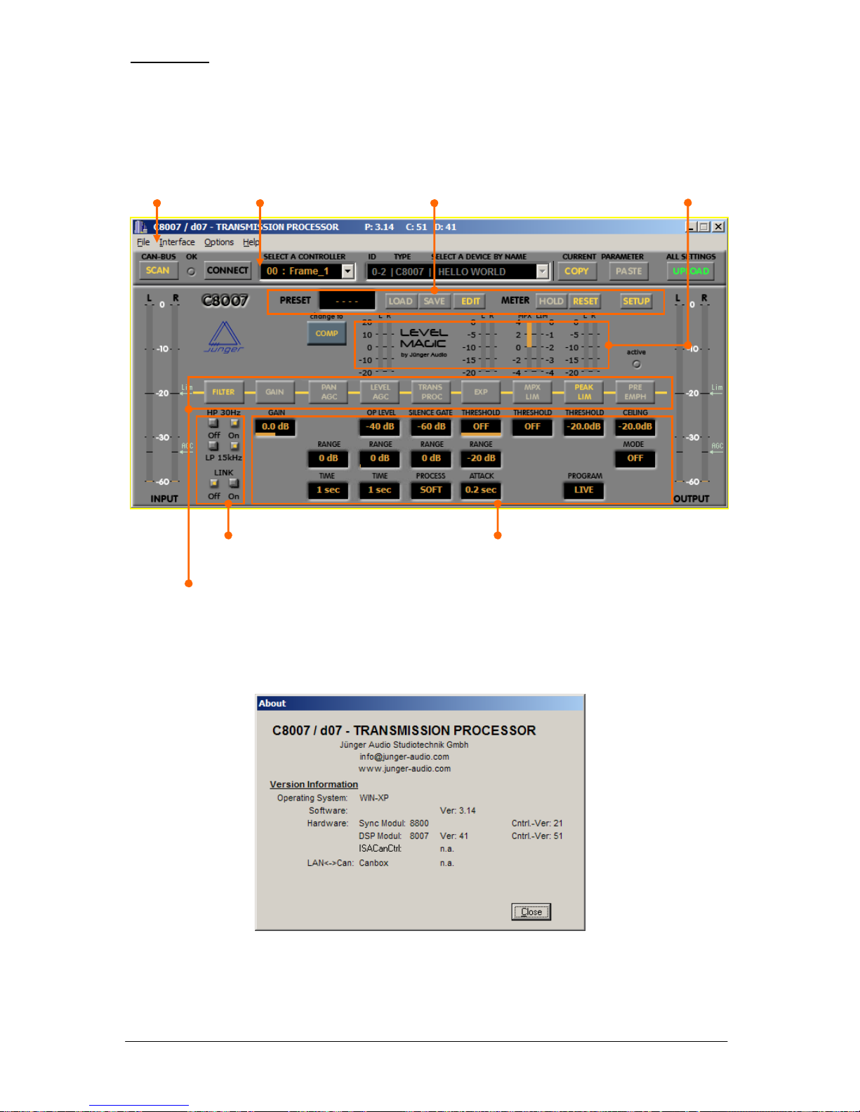
When closing the application it will write an INI-file into the installation directory and will use these
settings for the next time you run the application :
The GUI is divided into several sections. On the top you will find the MS-Windows menu bar.
From there you can load and store files, select the physical interface of the PC (TCP/IP), select two
operation options and set up TCP/IP.
There is no on line Help menu available, only the submenu <About> :
The About window shows some system information such as PC OS, device hardware information and
the DSP as well as the controller firmware of a device.
device communicationmenu bar
function buttons
p
arameter displays & drag label
p
reset control
p
ush button functions
p
rocessing display
Page 61
OPERATION
page 4-3
4.3 LOADING & SAVING FILES
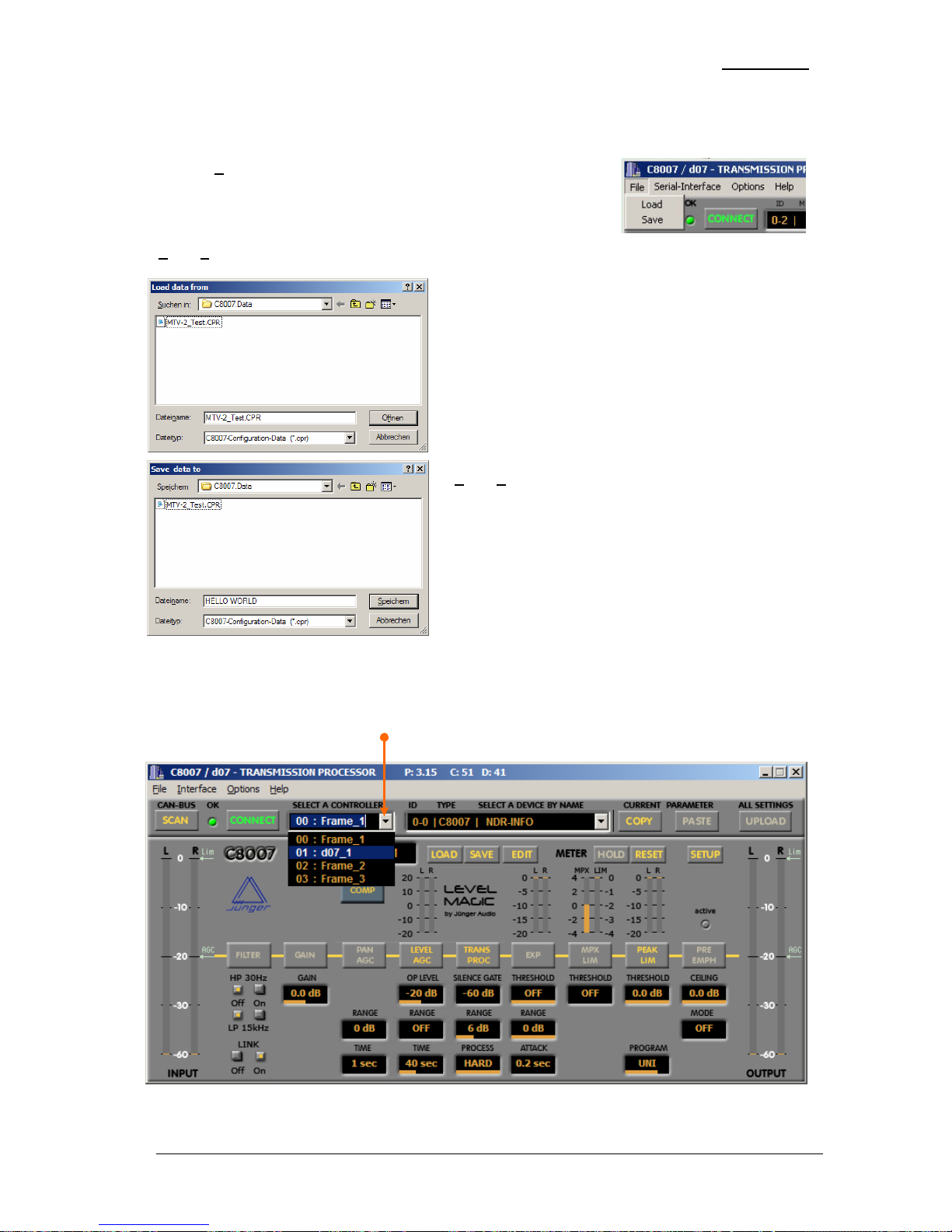
Click on > F
ile in the menu bar to open the drop down menu :
> F
ile > Load opens standard file open dialogue.
Select the requested file and click open in order to load
that file.
When loading a file the GUI will be automatically
disconnected from the device!
Now you can edit all settings from the file off line without
effecting the device under control.
It is also possible to save these settings by
> F
ile > Save.
This dialog will also be used when saving device
parameters from a connected device
This dialogue gives you the device name
as a default file name
4.4 SELECTING DEVICES
In bigger installations there are two steps to select a device.
First you must select one controller (server) from the many you have in your system :
When you have selected a controller the application will automatically look for that controller (server)
and will SCAN for devices if you have made a selection in the above pull down (see page 4-5).
Page 62
OPERATION
page 4-4
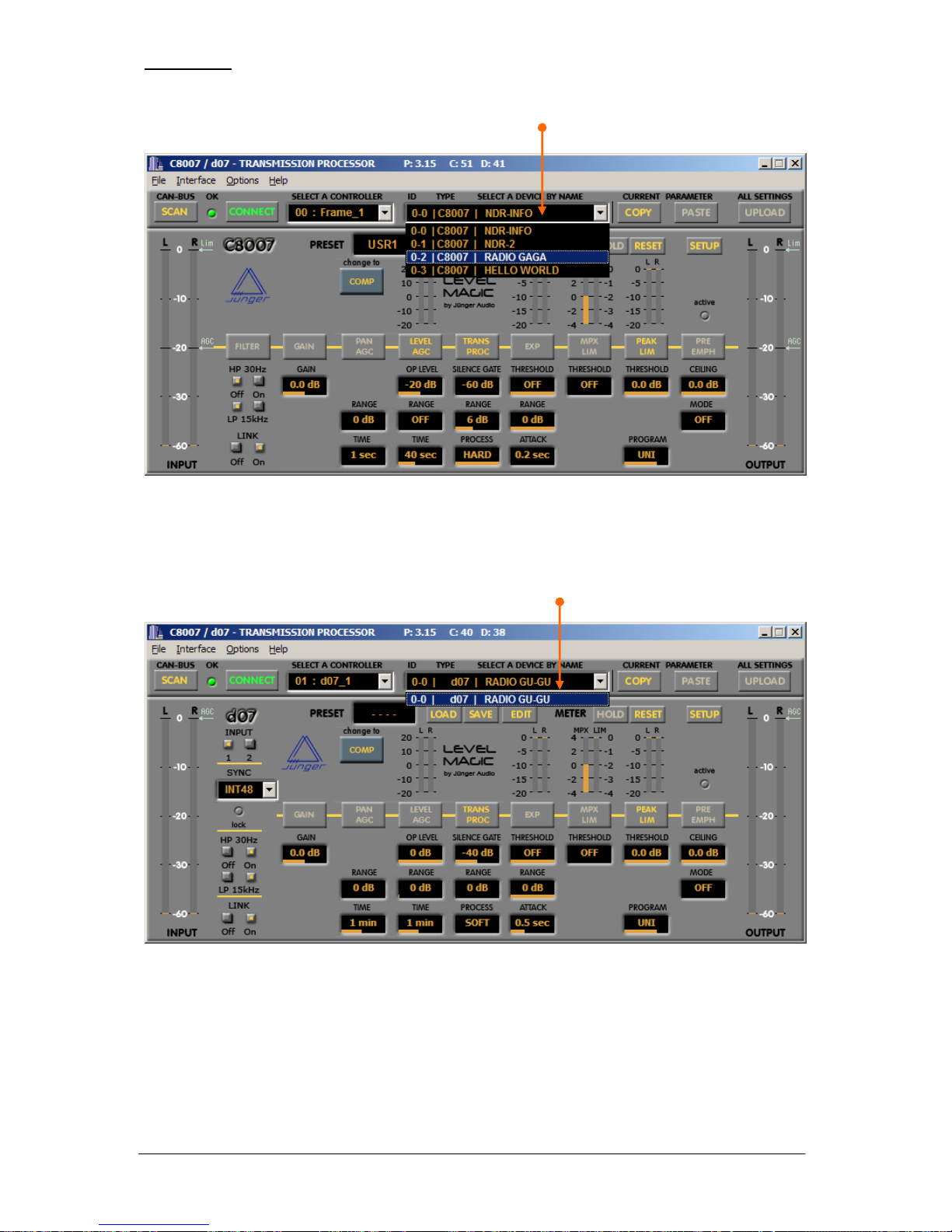
The next step is to select a device if you are connected with a C8k frame.
The C8702 system controller as well as the d07 Ethernet interface are talking internally via the
CAN-bus with the physical processing device(s). In a C8k system the devices are the processing
modules (C8007) while the d07 is treated as one device with almost the same behaviour as the
C8007.
For a d07 there is only one device. Therefore you do not need to make a selection.
Page 63
OPERATION
page 4-5
4.5 CONTROLLING THE DATA FLOW
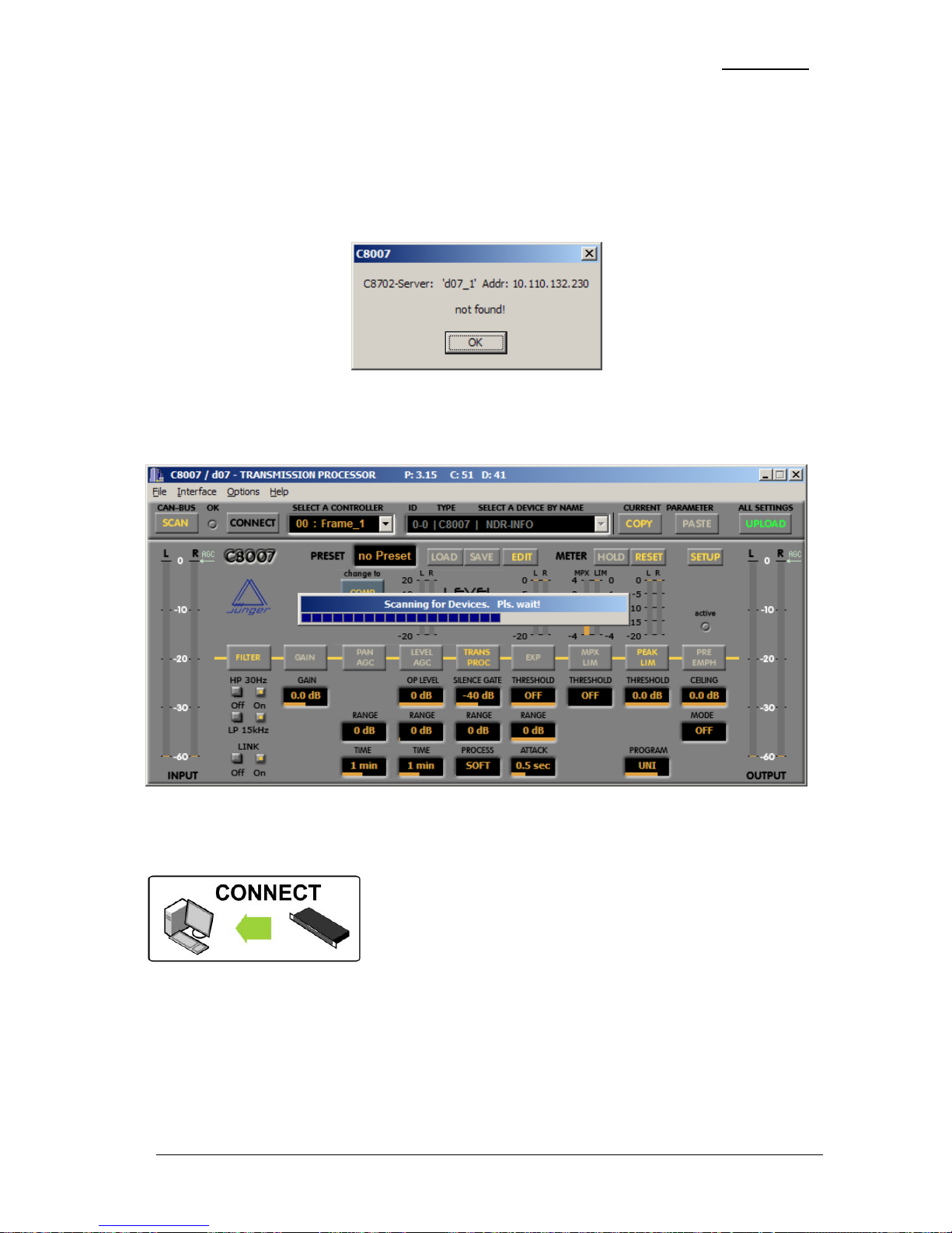
<SCAN>
Scanning is a process that will first of all connect with the server (controller).
If this fails you will get an error message :
It is a sign that something is wrong with your TCP/IP setup or the device is not connected with the
network or it is simply turned off.
The next step is to scan for available devices which are connected to the server :
This process will take a little while. The time depends on the Scan Min/Max values of the Setup
TCP/IP menu (see page 4-1).
<CONNECT>
Will connect the GUI with a selected device on demand or
reconnect it with the previous selected device. The parameters will
be downloaded from the device.
This action will overwrite the data of the GUI!
There is an option “Connect Automatically After Scan”. If it is checked the application will
automatically connect with the first C8007 device detected in a C8k frame or with the d07 processing
part.
OK
The “OK” soft LED can show :
green communication is o.k.
red communication is interrupted
grey TCP/IP communication with the server is established, no device connected
Page 64
OPERATION
page 4-6
The devices use a set of parameters which control the “on air” processing while a preset represents a
set of such parameters. Presets can be stored within the device and can be recalled at any time for
cross fading with the actual parameters to control the processing.
The presets may be manipulated in the background without influencing the “on air” parameters.
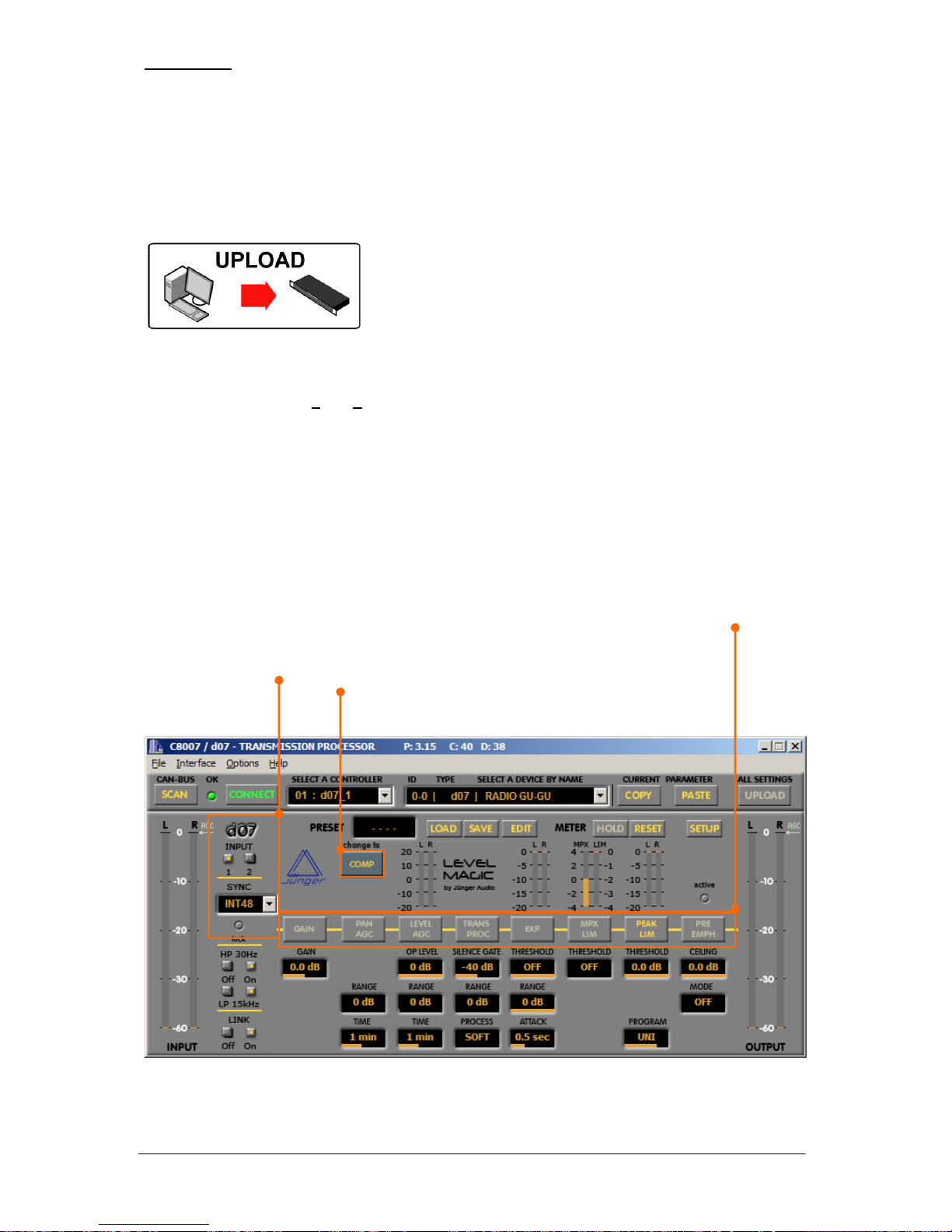
<UPLOAD>
The preset data of the application (originated from a file or
gathered from a device) will be sent to the previously connected
device.
There is an option : “Overwrite current parameters”.
“Current parameters” means the “on air” parameters of a device
or the actual parameters displayed in the GUI.
If this option is checked :
* the parameters which are displayed will be overwritten from the “on air” data of a file
when you perform a > F
ile > Load
* the active data of the device (“on air” parameters) will be overwritten when you perform an
<UPLOAD>.
<COPY>
Copies the parameters from the “on air” processing (i.e. displayed by the GUI) to a clip board.
<PASTE>
Transfers the parameters from the clip board into the “on air” processing of the selected device
4.6 PARAMETER EDITING
The GUI of the C8007control software represents a virtual signal flow of the processing.
The d07 section only appears if a d07 is detected and allows for hardware specific
settings of the d07
The soft button switches between the
operating modes: compressor / LevelMagic™
The above virtual signal flow depends on either the classical use of the compressor or the
LevelMagic™ features. For details of setting the parameters please refer to the respective manual.
Page 65
OPERATION
page 4-7
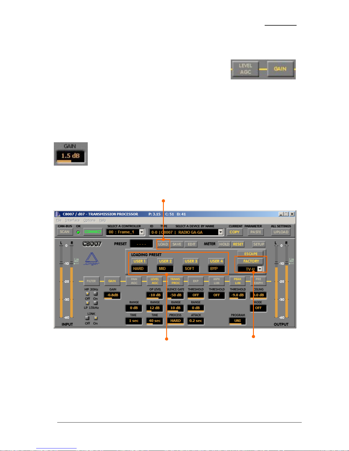
4.6.1 FUNCTION BUTTONS
The virtual signal flow is divided into processing sections represented
by a set of parameter windows and a 3D function button with a label
on it. The label will change its colour from grey to yellow if the value of
one of the processing parameter is in a range where this processing
section becomes active. Pressing such a function button will set the relevant parameters to a value
leading that processing section to become momentarily inactive – bypass function for that section.
4.6.2 DRAG LABEL
The DRAG LABEL is a GUI tool to adjust the related parameter. The parameter value is displayed
numerically and by a bar within the label. For doing changes of parameters you must bring the mouse
cursor over the label. Holding down the left mouse button and moving the mouse horizontally will
change the value in fine steps but slowly. Holding down the right mouse button will
change the value in big steps but fast. Clicking on the right mouse button when the
mouse arrow is close to the horizontal edges of a drag label will make it jump to the
respective boundaries of the values.
4.7 LOAD PRESETS
While “on air” you can load a preset from the devices memory.
From here you can select one of the USERx or one of the FACTORY presets stored within the
device.
Page 66
OPERATION
page 4-8
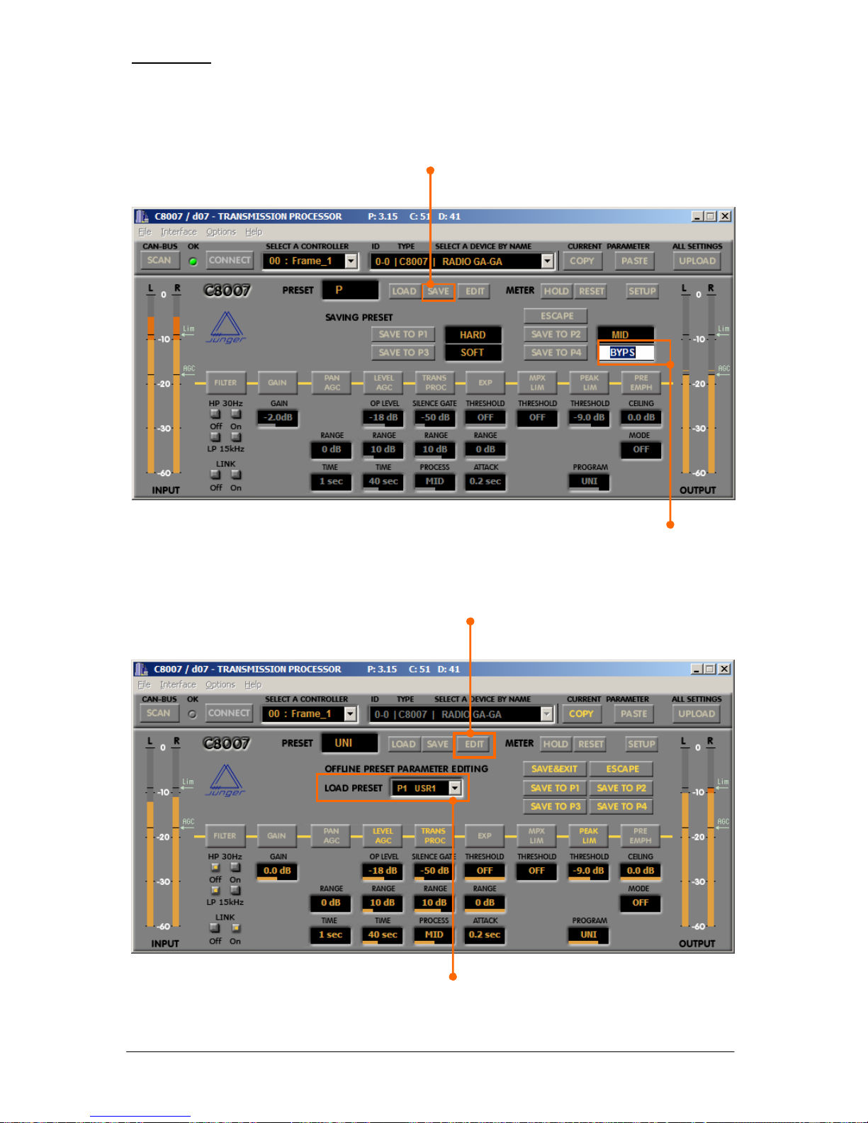
4.8 SAVE PRESETS
If you are happy with your actual “on air” parameters you can save these parameters to one of the
USERx memories of the device. Press <SAVE> and the GUI will give you the option to select one
of the preset memories P1 – P4.
When you press one of the soft buttons you will be able to change the name of the preset.
If you do not want to change it, simply press <ENTER> and you are finished.
4.9 EDIT PRESETS “OFF LINE”
When you press the <EDIT> soft button, the application will be disconnected from the device and
the GUI will open this window :
Now you can load a preset from the devices memory into the GUI and make changes to the
parameters by using the drag labels.
This action takes place in the background of the processing i.e. the actual audio processing
will not be influenced by the preset edit function.
Page 67
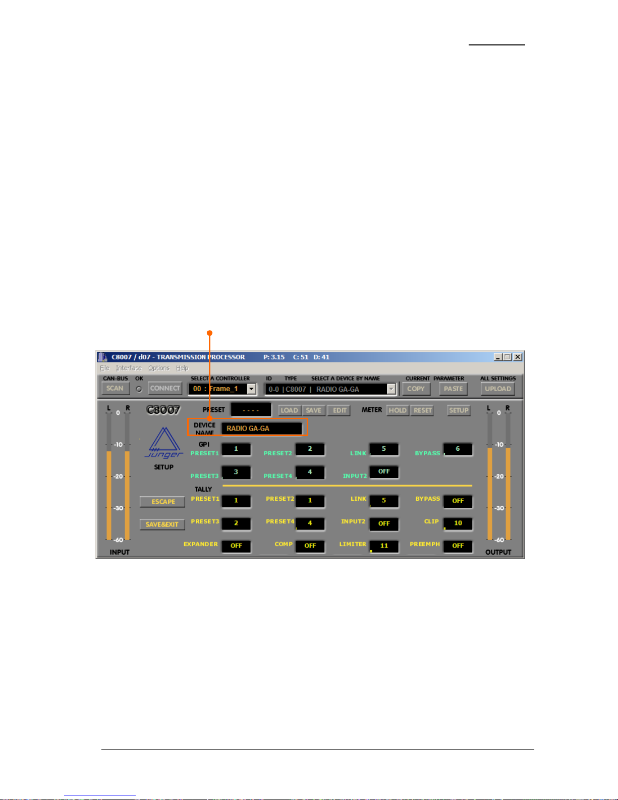
OPERATION
page 4-9
The GUI gives you the option to do this “off line” editing with all four presets one after the other
because the application will keep all data in the PCs memory. If you have finished the editing you can
press <SAVE&EXIT>. All settings will be transferred to the device and the application will reconnect
with the device and the GUI will show the “on air” parameters of the connected device again.
When you are in the “off line” edit mode, you can also store the actual settings visible in the GUI into
one of the other presets by pressing <SAVE TO Px>.
This action will only store the parameters but not the name i.e. the name of the preset where
you store the data will be preserved.
If you want to edit the preset name you must load that preset. Now you must click into the preset
name field and change the name of that preset (press <ENTER> to end the edit function of the name).
Finally you must press <SAVE TP Px> or <SAVE&EXIT>.
You can abandon the “off line” edit mode by pressing <ESCAPE>.
4.10 DEVICE SET UP
When pressing the soft button <SETUP> you can make hardware related settings such as GPI / Tally
assignment to device functions and you can give the device a unique name. You must click into the
related window to edit the device name. <ESCAPE> will leave the settings unchanged.
Pressing <SAVE&EXIT> will store the settings into the devices memory and will activate the settings.
<ESCAPE> will abandon the set up procedure.
Page 68

Page 69

END USER LIECENSE AGREEMENT
page 6-1
5. END USER LICENSE AGREEMENT
END USER LICENSE AGREEMENT FOR JUNGER AUDIO SOFTWARE
IMPORTANT—READ CAREFULLY: Be sure to carefully read and understand all of the rights and
restrictions described in this End-User License Agreement ("EULA"). Your usage of this software
constitutes your acceptance of the terms of the EULA.
For your reference, you may print the text of the EULA from this page now.
This EULA is a legal agreement between you (either an individual or a single entity) and Junger Audio
Studiotechnik GmbH (SELLER) for the software accompanying this EULA, which includes the
accompanying computer software, and may include associated media, printed materials and any
"online" or electronic documentation ("SOFTWARE"). By installing the SOFTWARE, you agree to be
bound by the terms of this EULA. If you do not agree to the terms of this EULA, you may not install or
use the SOFTWARE.
Software PRODUCT LICENSE
The SOFTWARE is protected by copyright laws and international copyright treaties, as well as other
intellectual property laws and treaties. The SOFTWARE is licensed, not sold.
1. GRANT OF LICENSE. This EULA grants you the following rights:
Software. You may install and use one copy of the SOFTWARE on a single computer.
Storage/Network Use. You may also store or install a copy of the SOFTWARE on a storage device,
such as a network server, used only to install or run the SOFTWARE on your other computers over an
internal network; however, you must acquire and dedicate a license for each separate computer on
which the SOFTWARE is installed or run from the storage device. A license for the SOFTWARE may
not be shared or used concurrently on different computers.
2. RESTRICTIONS.
• You must maintain all copyright notices on all copies of the SOFTWARE.
• Limitations of Reverse Engineering, Decompilation and Disassembly. You may not reverse
engineer, decompile, or disassemble the SOFTWARE, except and only to the extent that such
activity is expressly permitted by applicable law notwithstanding this limitation.
• Rental. You may not rent or lease or lend the SOFTWARE.
• Software Transfer. You may permanently transfer all of your rights under this EULA, provided
you retain no copies, you transfer all of the SOFTWARE (including all component parts, the
media and printed materials, any upgrades, this EULA and, if applicable, the Certificate of
Authenticity) and the recipient agrees to the terms of this EULA. If the SOFTWARE portion is
an upgrade, any transfer must include all prior versions of the SOFTWARE.
3. TERMINATION. Without prejudice to any other rights, SELLER may terminate this EULA if you fail
to comply with the terms and conditions of this EULA. In such event, you must destroy all copies of
the SOFTWARE and all of its component parts.
4. COPYRIGHT. All title and copyrights in and to the SOFTWARE (including but not limited to any
images, photographs, animations, video, audio, music, text and "applets," incorporated into the
SOFTWARE), the accompanying printed materials, and any copies of the SOFTWARE, are owned by
SELLER or its suppliers.
Page 70

Page 71

B 6 – Network Integration
NETWORK INTEGRATION
of Jünger Audio devices
d07
d06
Level Magic LT
C8000-modules via C8702 LAN Controller
To operate the Junger audio devices via web browser you have get an Ethernet
connection DEVICE < - > PC. If you are not familiar with the network setup, please
consult a network administrator for assistance and read ALL the manual carefully!
There are two ways to communicate with the device via ethernet:
1. You can connect the device to the LAN your PC is integrated (if there is one
existing already)
2. You can connect the device directly to your PC using an Ethernet crossover
cable.
In both cases network settings of the device or your PC or even both have to
be changed and matched.
The default network configuration of the Jünger devices is:
IP Address: on a label at the Ethernet connector socket at the rear of the
device
Netmask: 255.255.0.0.
Gateway: 10.110.0.1.
1. Integration into existing LAN
When you want to integrate the device into an existing LAN you have to change its
IP-address, the (sub)network mask and the gateway. You will get valid settings
from your network administrator.
You can do that two ways:
A Connecting the device over a serial cable to your PC and change the
network configuration with a terminal program (e.g. HyperTerminal
included in Windows installation)
B Disconnect your PC from your LAN (physically), match your PC’s network
setup to the setup of the device for getting access to the device via
Ethernet crossover cable, change the device’s network configuration via
Ethernet crossover cable. Then change again your PC’s configuration and
connect both your PC and the device to the LAN.
B 6
Page 72
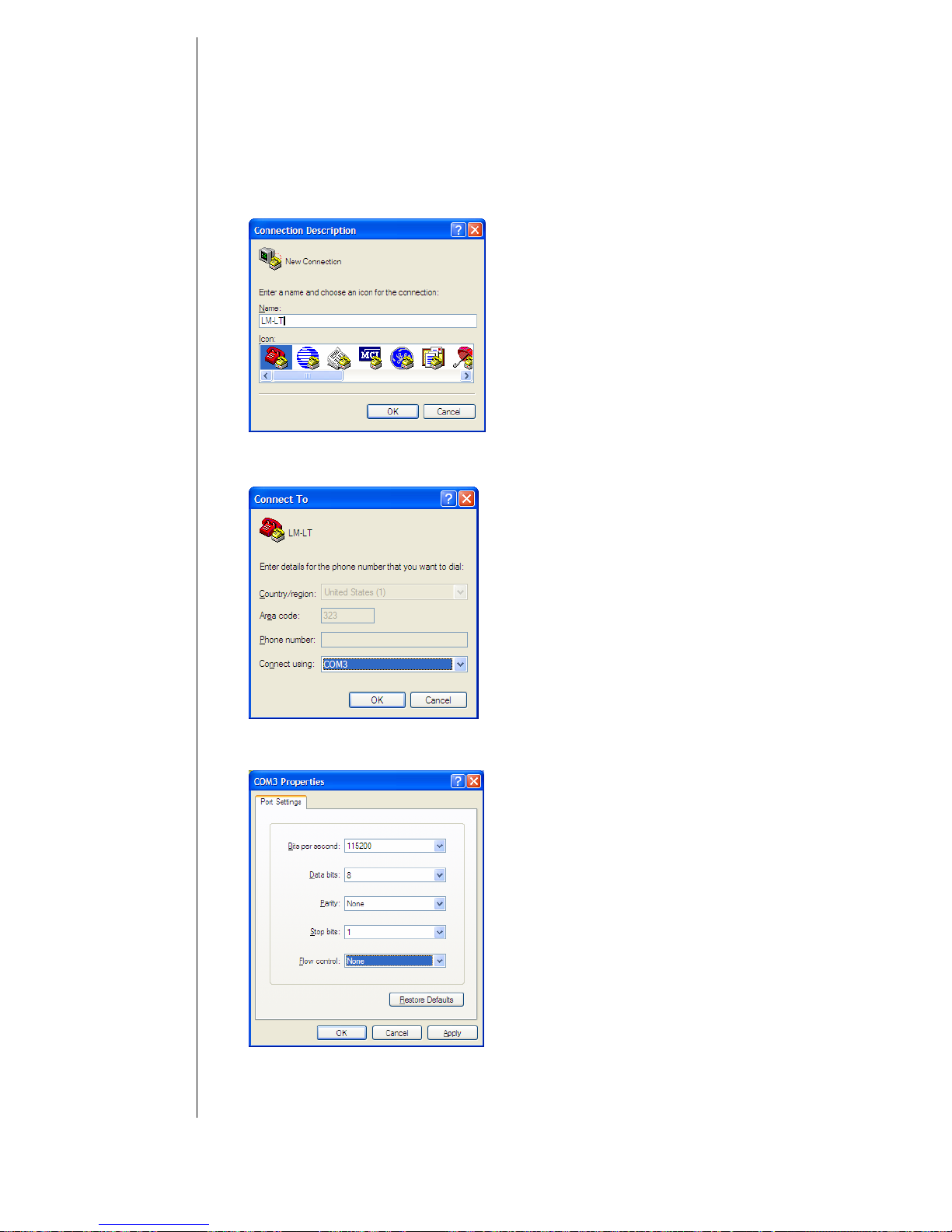
B 6 – Network Integration
A) Connect the device over a 9 pin serial cable (connected 1
to 1) to your PC. Start your terminal program (e.g. Start ->
Programs -> Accesoires -> Communications -> HyperTermin al).
Enter a name of your choice and press OK
Choose the connection port you are working with and press OK
Set the COM settings as they are shown in the window above and press OK.
Page 73
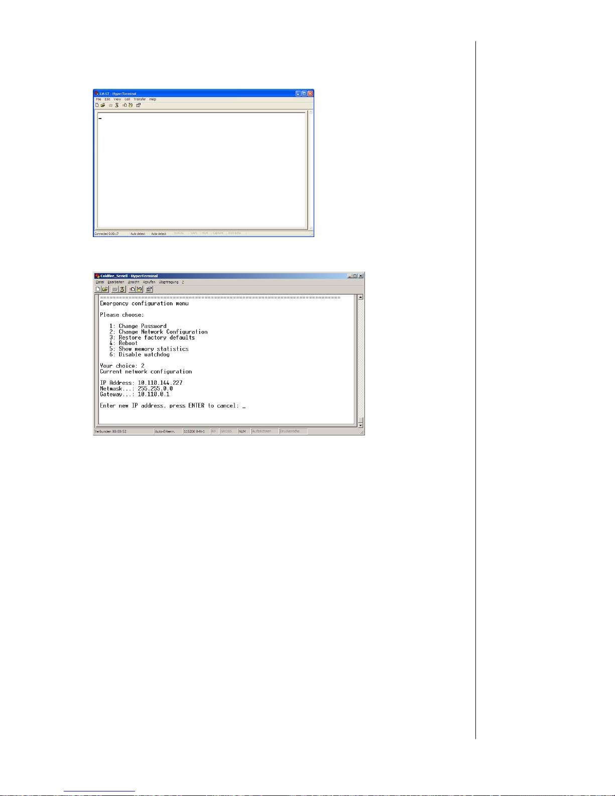
B 6 – Network Integration
You will get to the Hyper terminal window:
Press ENTER and you will get the following information of the device:
Now you can change the network configuration so that it fits into your LAN.
You might have changed the IP-address of the device, so please renew the label at
the rear of the device, otherwise it will cause confusion.
When you ever initialize the device the default IP-address and network
configuration will be active again. In case of need you can read the default IPaddress always on the controller in the device!
B) You can also change the IP address of the device over Ethernet connection.
Disconnect your PC from the LAN, connect it to the device directly via Ethernet
crossover cable (not connected 1 to 1, but 1 to 8 etc…). Change the network
configuration of your PC (write down the current settings, you need them later to
reconnect to your LAN!) via “Local Area Connection Properties” (Windows: Start ->
Settings -> Network connections -> Local Area Connections)
Page 74
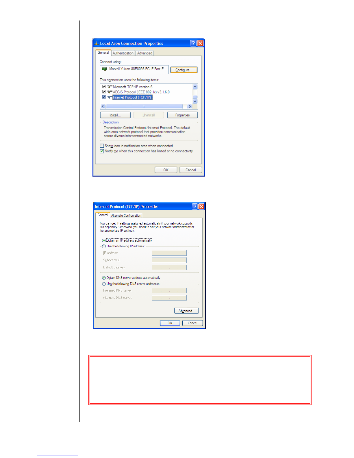
B 6 – Network Integration
Scroll in the list and choose Internet Protocol (TCP/IP).
Make sure that the ‘check box’ for this item is checked, and then click on PROPERTIES.
In this example, the Ethernet TCP/IP is set to ‘Obtain an IP address automatically.’
If, in your case, it is set to
‘Use the following IP address,’
jot down the current settings on a piece of paper
(IP address, Subnet Mask, and Default gateway, if used).
You will need them later to restore the IP address of the PC to what it is required
to work on your LAN.
Page 75
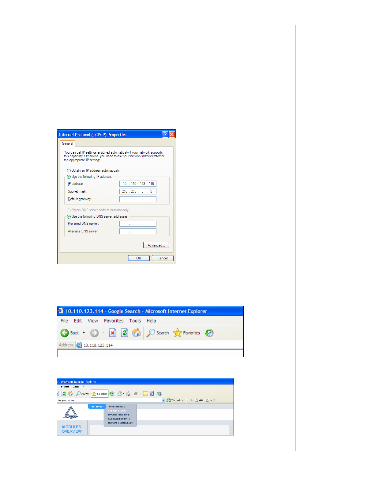
B 6 – Network Integration
Then change the settings in order to be able to communicate with the device. You
have to choose an IP-address “near” to that of the device.
So if the settings of the device are e.g.
IP Adress: 10.110.123.114
Netmask: 255.255.0.0.
Gateway: 10.110.0.1.
You have to take 10.110.123.115 as IP-adress (or something near to the device’s
address, only 10.110.123. have to be the same!) and the same netmask. The
gateway is not important when you are using an Ethernet crossover cable.
When you have changed the settings press OK. Now you will be able to
communicate from PC to device via web browser (e.g. internet explorer) with an
Ethernet crossover cable. Just type in the device’s IP-address into your browser:
Then you will come to the modules web page:
Page 76
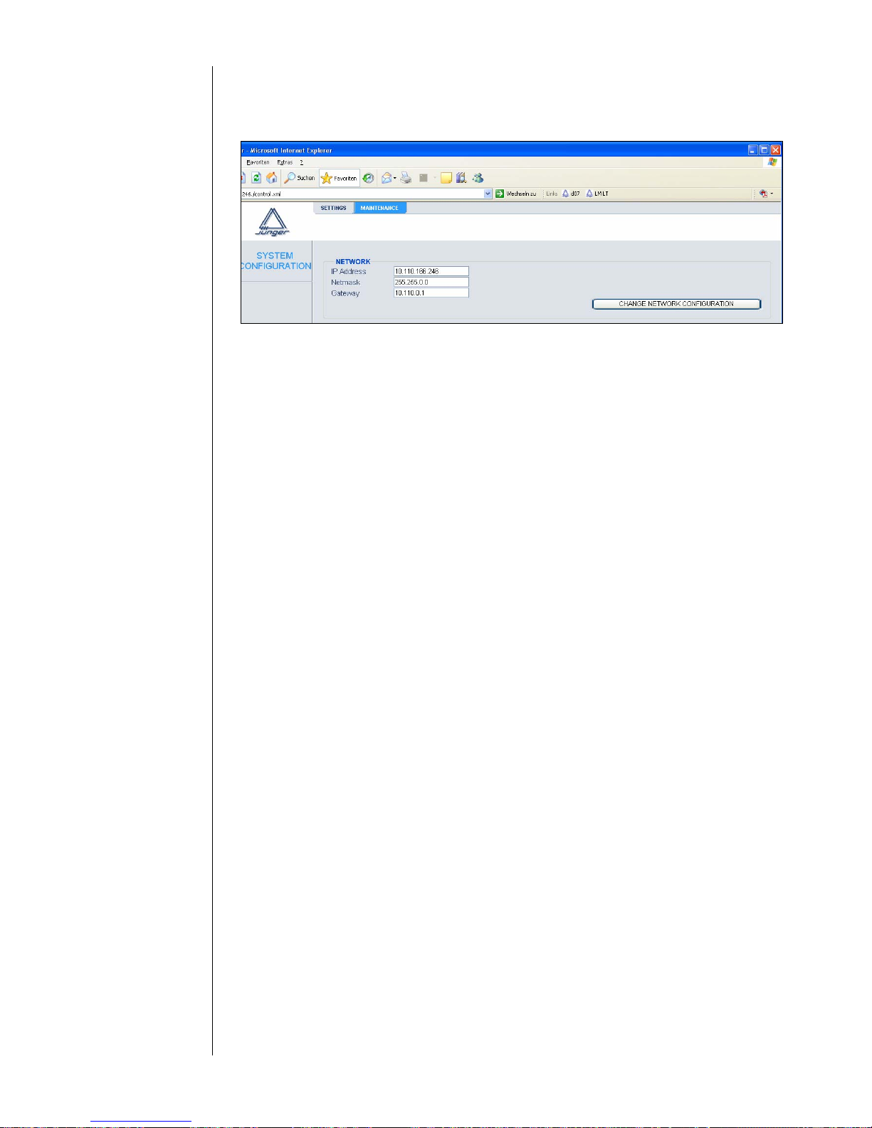
B 6 – Network Integration
Under MAINTENACE -> SYSTEM CONFIGURATION you will be able to change the
device’s network configuration according to the settings of the LAN you want to use.
After having changed the settings click CHANGE NETWORK CONFIGURATION and
after that REBOOT THE CONTROLLER (Maintenance -> Reboot Controller).
Rebooting the device activates the changes you have made to the network
configuration. If you changed the IP address of the device, you may not be able
to reach the web interface after the reboot.
Now you have to change the settings of your PC network configuration again and
connect both the PC and the device to the LAN you want to use. Then you will be able
to communicate with the device over web browser via the chosen IP-address.
2. Connection via Ethernet crossover cable
When you want to communicate with the device via Ethernet crossover cable you can
C change your PC network settings and match them to those
of the device
OR
D keep your PC network settings and change the ones of
your device.
C) to change the PC network settings please refer to 1.B. Follow the instructions till
you get to the modules web page. And you are done!
D) if you want to keep the PC network settings you can either
match the device’s configuration via serial conn ection (see
1.A
) or you have to do the procedure explained in 1.B.
After having done the reset of the PC’s network
configuration you will be able to communicate with the device via
Ethernet crossover cable.
Page 77
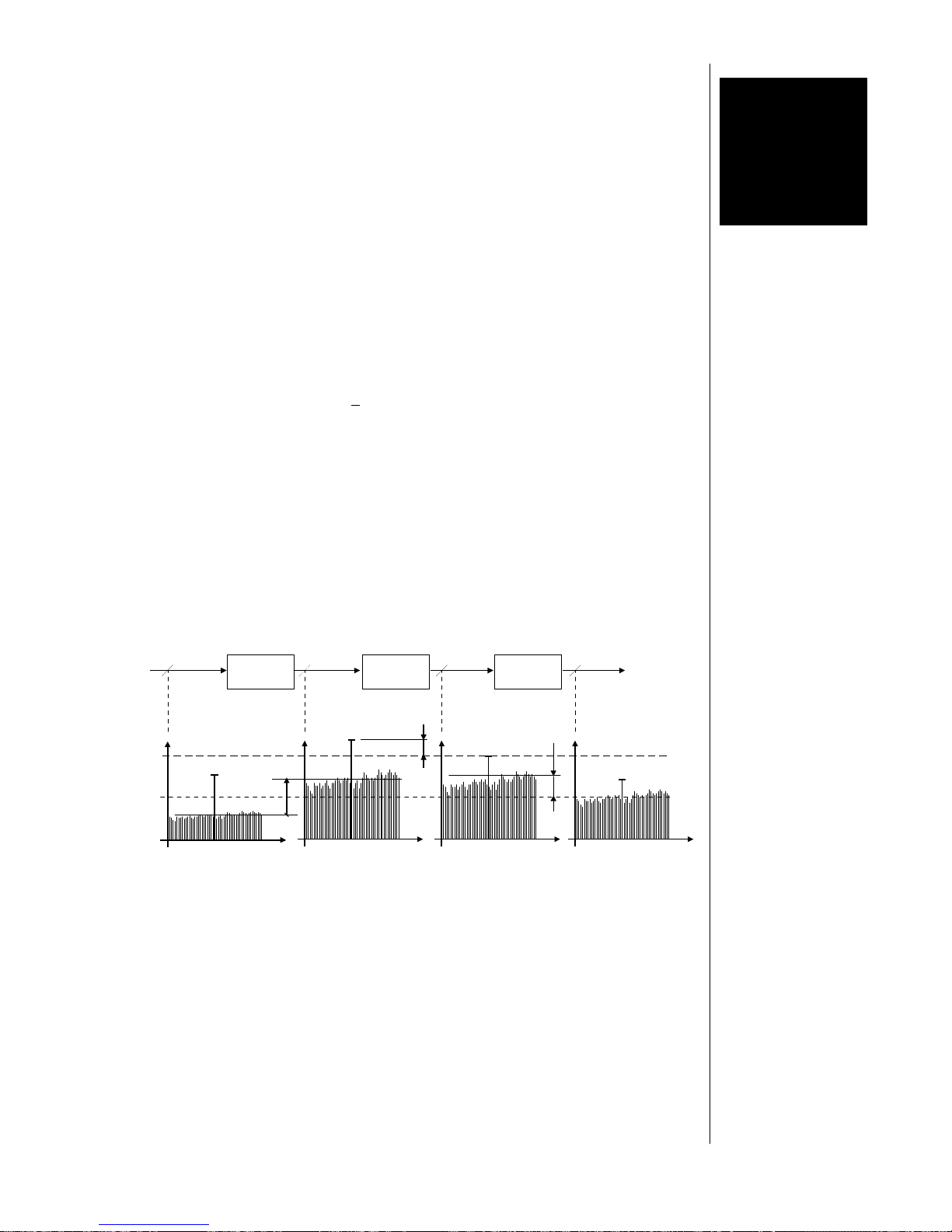
B 7 FM-Transmission d07
FM-TRANSMISSION – d07
There are two important parameters for FM-Transmission
The frequency deviation, determined by the peak level of the signal
The MPX-Power, determined by the energy of the signal
International standards regulate the maximum values that have to be kept tight so
that neighbouring transmitters will not be disturbed.
Frequency deviation +
75kHz
MPX-Power 0 dBr
The job of the d07 processor is standard compliance controlling of FM signal
energy within permissible peak deviation.
The compression of the program signal causes an increase of the signal energy
and, therefore, more loudness, but also more modulation power (MPX power). Too
much compression will cause the permissible value of the multiplex power to be
exceeded and the MPX limiter must reduce the total signal. As a consequence, the
peak levels as well as the average levels are reduced, leading to a reduced
loudness, as outlined below :
Input signal compressor out peak limiter out MPX limiter out
peak
level
MPX
level
Compressor Peak limiter MPX limiter
Input Oputput
peak
reduction
MPX power
reduction
compression
It is necessary to break up this “vicious circle” by optimal setting of GAIN and
compression. The optimisation of parameters should be done in a way that neither
the peak limiter nor the MPX-limiter permanently show GAIN-REDUCTION. The
program signal limitation should only occur briefly in order not to deprive it of all
dynamic properties. The average modulation power can only be optimized by
tweaking linear GAIN and the COMPRESSOR as well.
B 7
7.1.
General
7.2.
MPX-
Page 78
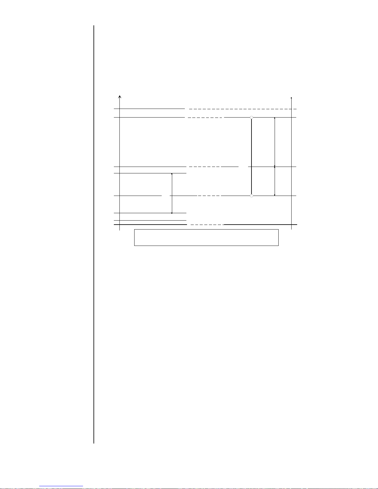
For alignment of the d07 it is important to consider the level diagram of the overall
transmission chain (see below):
0dB
r
19,0
40,0
Reference deviation
6,7
Pilot tone level
75,0
FM - peak deviation
Peak limiter reference point
-4,4dBFS
68,3
Peak deviation without pilot tone
kHz
Operating level
+4,6 dB
30,0
12,0
+4dB
r
-4dB
r
ITU BS 416-6 / CCIR 412-5 defines MPX power as relative average of modulation power
mesured over a period of 60 sec. It shall be equivalent to the power of a stationary signal
that causes a frequency deviation of 19kHz
-6,5dB
alignment
reference level
+6dBu / -9dBFS
Peak level
Range to adjust
d07 MPX Power
Peak level and MPX level
linked steady by d07
-11,1dBFS
MPX level
below peak
level
Frequency deviation - FM transmitter
Audio level - output of
d07
dBFS
The threshold of the peak limiter (limiter threshold) determines the maximum output
level of the d07. This value is the most important setting parameter. It serves at the
same time as the reference point for the MPX limiter, the adaptive pre-emphasis and
the compressor.
An MPX level of 0dBr lies 11.1 dB below the limitation point of the limiter of the d07
and is fixed to it. This value is given by the relation of multiplex power level of 0dBr
(19kHz frequency deviation) to peak level (75kHz frequency deviation). For special
applications the MPX level can be changed by + 4dB respectively.
The operating level in standard studio environment is not the peak level but the
nominal level of +6dBu e.g. (analog) or –9dBFS (digital). This level will also be used to
line up the FM transmitter and shall cause a nominal modulation deviation of +40kHz.
The headroom of 4.6dB left to the peak level (peak deviation respectively) can be
exploited for temporary signal peaks or for the pre-emphasis of higher signal
frequencies.
With a given nominal level the threshold of the peak limiter may not exceed this
nominal level by more than +4.6dB because otherwise the peak frequency deviation
level will be exceeded. Therefore the transmission path must be aligned in a way that
the nominal output level of the d07 will generate a signal at the output of a MPXencoder that causes a deviation of +40kHz. Afterwards the peak limiter of the d07
must be set so that the peak deviation is limited to +75kHz.
Level
diagramm
Operation
Level
Peak Level
MPX-Limiter
Setup hint
Page 79
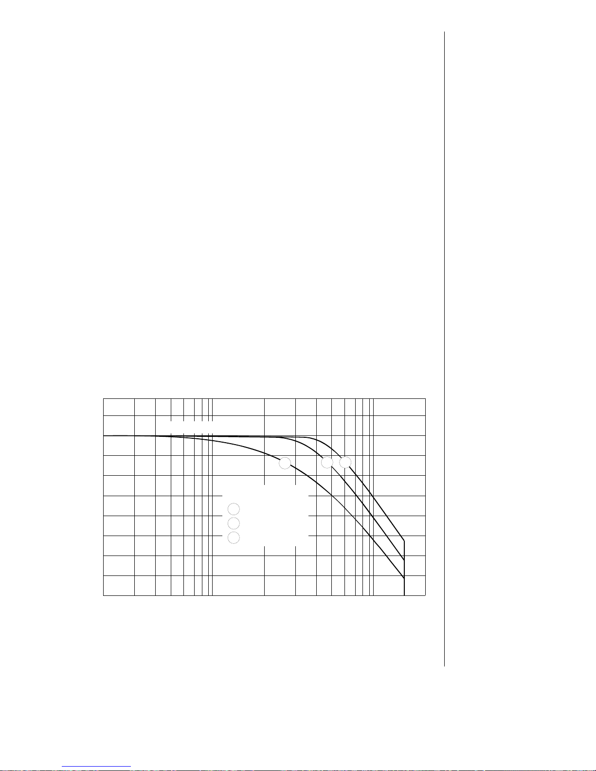
B 7 FM-Transmission d07
To enhance the signal to noise ratio for FM transmission, Pre-Emphasis on the
transmission end and De-Emphases on the receiving end is used. Higher
frequency signal components are raised following a standardized filter curve and
leads to an increased drive of the trans mitter . Th is leve l pu ll up mus t b e cons ider ed
for the limitation of peak levels.
In the d07 the signal reaches a dynamic low path filter after a broad band limiter.
The cut-off frequency of this filter is controlled adaptive and time depending. The
attenuation of the filter for high signal components is controlled in a way that it
compensates exactly for the increase of high frequencies by Pre-emphasis on the
transmitting end. This alteration of the frequency response is only effective
temporarily and will practically not be recognizable for normal program material
because the processing time is below the integration time of the human ear.
The threshold of the limiter can now be set in a way that maximum deviation is
achieved for low frequencies. Higher frequency components will be reduced if
necessary and do not cause an overshooting of the peak deviation.
If the program material has a lot of high frequency components the activity of the
adaptive filter is of course more frequent and will eventually be audible.
If the threshold of the peak limiter is not set to maximum but some dB’s below the
resulting headroom can be used for higher frequency components.
The operation of the adaptive pre-emphasis filter also happens in this case only
when the maximum value is exceeded, i.e. depending on the headroom at higher
frequencies only. By using the parameter PRE_EMPHASIS THRESHOLD, the
operating point for the control of the filter can be set. Caused by this mode of
operation this value can only be higher or equal to the threshold of the peak limiter.
500 1k200 2k 5k 10k 20k
-18
-16
-14
-12
-10
-8
-6
-4
-2
0
-18
-16
-14
-12
-10
-8
-6
-4
-2
0
1
2 3
d07 Pre-Emphasis
Parameter:
Preemp hasis Threshold
1
2
3
- 4,0dBFS
-2,0dBFS
0,0dBFS
Limiter Threshold -4dBFS
Due to the different adjustable thresholds for peak limiter and adaptive preemphasis, an optimisation in regard to maximum level and sound balance can be
achieved. This optimisation should also be done under consideration of the
multiplex power because higher frequency components caused by a level increase
on the transmitter side will make a higher contribution to the overall power.
7.3.
Preemphasis
Pre-emphasis
Threshold
Pre-emphasis
Set up hint
Page 80
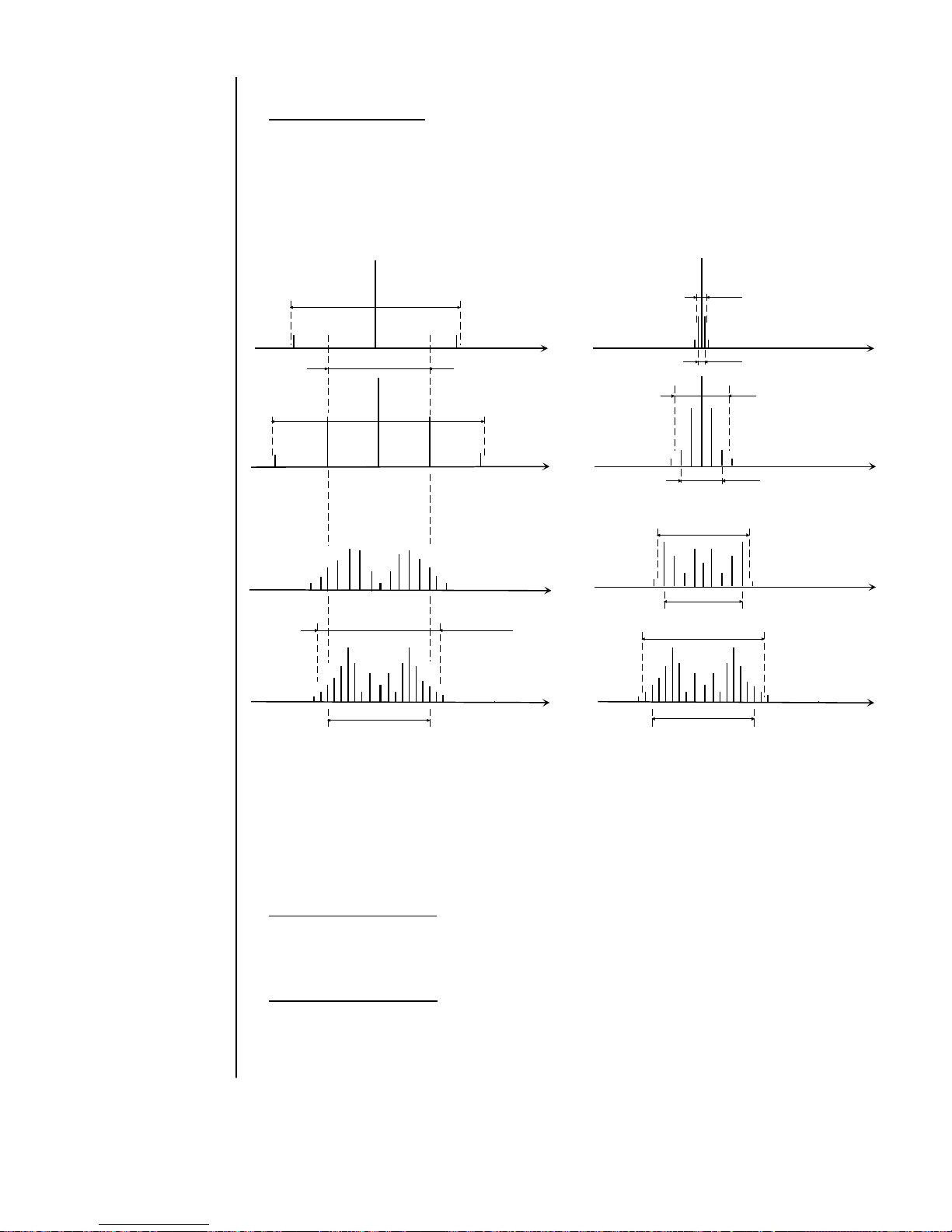
Frequency modulation
The sketch below shows the principal influence of the modulation index m= Δfc / fm to
the spectrum of an FM signal. On the left side the frequency deviation Δfc (amplitude
of the modulating signal) is constant but the modulating frequency fm changes. On the
right hand the modulating frequency fm is constant but the frequency deviation Δfc is
changing :
f f
m = 0,5
Δ
f
c
= 1kHz
f
m
= 2kHz
m = 0,5
Δ
f
c
= 0,05kHz
f
m
= 0,1kHz
f f
m = 1,0
Δ
f
c
= 1kHz
f
m
= 1kHz
m = 1,0
Δ
f
c
= 0,1kHz
f
m
= 0,1kHz
f
m = 5,0
Δ
f
c
= 1kHz
f
m
= 0,5kHz
m = 5,0
Δ
f
c
= 0,5kHz
f
m
= 0,1kHz
f
m = 10,0
Δ
f
c
= 1kHz
f
m
= 0,1kHz
f
B = 2*f
m
f
m = 10,0
Δ
f
c
= 1kHz
f
m
= 0,1kHz
B
B ~ 2 (Δfc + fm)
B
B
B
2Δ
f
c
2Δ
f
c
2Δ
f
c
2Δ
f
c
2Δ
f
c
2Δ
f
c
B = 2*(Δ
fc + f
m
)
You can show that a bandwidth of approx B ~ 2 * (Δfc(max) + fm(max)) is needed for
FM modulation for high rejection of high frequency signals. With a maximum
frequency deviation of 75kHz and 15kHz cut-off-frequency of the modulating signal B
will be ~ 180kHz. Based on this fact the planning of transmitter positions and power
takes place for area-wide feed. To prevent disturbance in adjacent channels the
maintaining of the frequency deviation needs the highest attention.
Frequency deviation Δfc
Value of deviation of the mean frequency from the transmitting frequency of a FM
transmitter caused by the amplitude of the modulating signal.
Peak Deviation Δfc(max)
Maximum frequency deviation allowed for an FM transmitter. Defined by the ITU to
+ 75kHz
7.4.
Terms and
definitions
Page 81
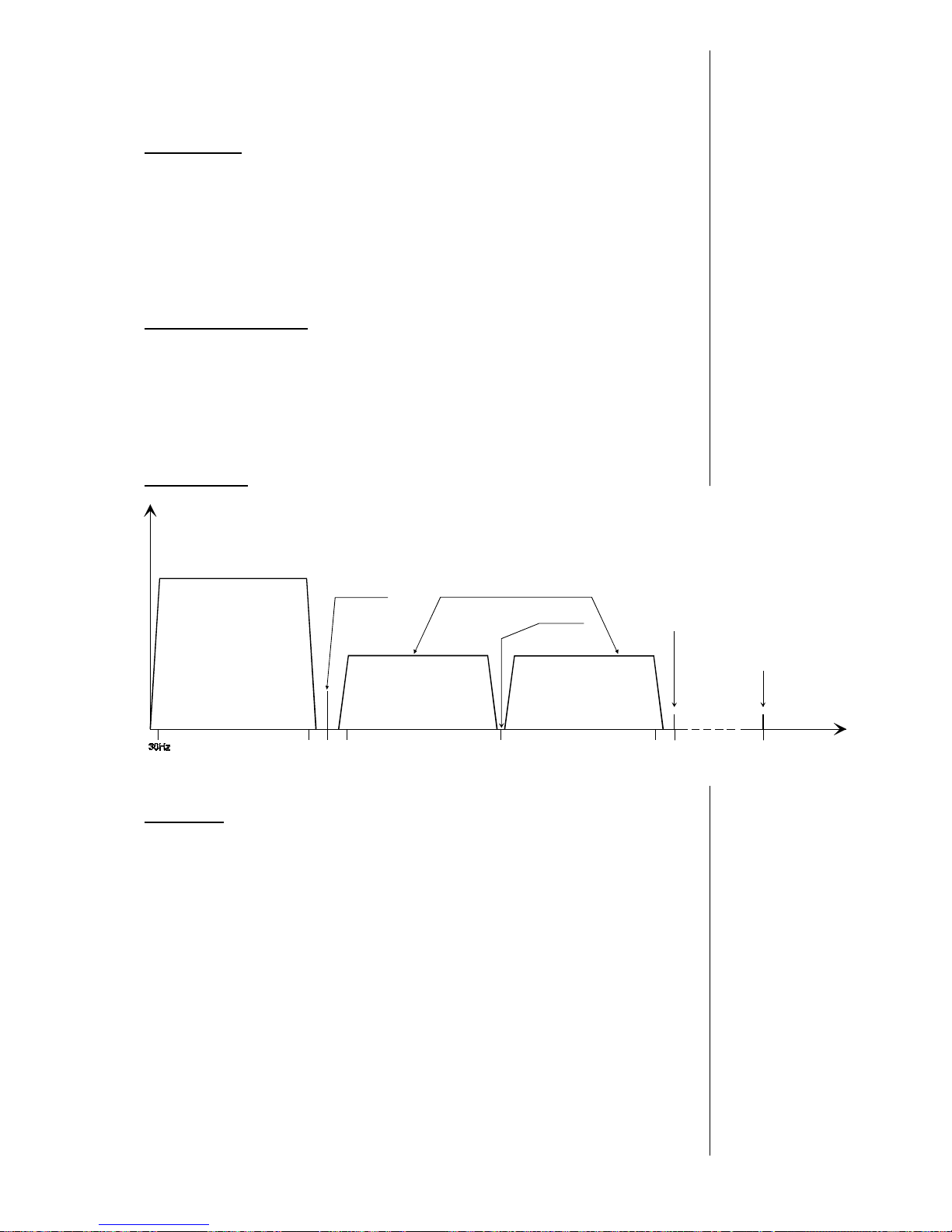
B 7 FM-Transmission d07
Pre-Emphasis
Increase of high frequencies to enhance the signal to noise ratio for FM
transmission equals to a time constant of a high pass filter of 50μs in Europe and
75μs in America. It will be laterally reversed at the receiver end. This value does
not comply with todays spectrum of audio signals. But it is not possible to change it
because of the innumerable receivers. Therefore modern audio signals may easily
over drive an FM transmitter, causing nasty interferences.
Adaptive Pre-Emphasis
Function of the d07 that makes it possible to dynamically accommodate the level of
an audio signal to the high frequency boost of an FM transmitter. The effect is that
over driving by high frequency signal components in critical programs will be
avoided (s.a. pre-emphasis).
MPX-Spektrum
38231915
53
Differential signal
(L - R) = S
Auxiliary carrier
- pilot ton -
Illustration of base band spectrum of a MPX signals
Frequenz
in kHz
Compatible monaural signal
(L + R) = M
Spectrum of
MPX signals
Double sideband
suppressed carrier
power of the M - signal
proportional to the square of the
amplitude of the M-signal
P
M
~ M
2
power of the (-S) - signal
proportional to the square of the
amplitude of the (-S) - signal
P
-S
~ (-S)
2
57 76
RDS
(Radio Data System)
auxillary carrier
DARC
(DAta Radio Channel)
auxcillary carrier
power of the (+S) - signal
proportional to the square of the
amplitude of the (+S) - signal
P
-S
~ (+S)
2
MPX-power
Overall power of the Multiplex signal from the sum of components of the MPX
spectrum :
Monaural signal (M=L+R)/2 30Hz to 15kHz base band
Auxiliary carrier 19kHz approx 9% of overall power
Double side band suppressed 23kHz to 38kHz lower side band
carrier modulation (S=L-R)/2 38kHz to 53kHz upper side band
RDS signal
DARC signal
Page 82
 Loading...