

Page 1
4ch digital audio limiter
b41
release 2.3.0
Page 2

Page 3

The information contained in this manual is subject to change without notice.
This manual is the copyright of Jünger Audio. All reproduction and copying, other than for
legal owner’s personal use, or disclosure of part or whole to a third party, is not allowed
without prior written authorization by Jünger Audio. © Jünger Audio, Berlin 1998-2004
FOREWORD
Thank you for buying and for using the 4-channel Digital Audio
Limiter b41.
Not only you have acquired the latest generation of digital
dynamic range processing, but also a piece of equipment which
is unique in its design and specification.
Please read this manual carefully to ensure you have all the
information you need to use the 4-channel Digital Audio Limiter
b41.
The unit was manufactured to the highest industrial standards
and went through extensive quality control checks before it was
supplied.
If you have any comments or questions about installing, settingup or using the b41, please do not hesitate to contact us.
0
Page 4

CONTENTS
2. Function description .......................................….
2.1 Basic description ...........................................
2.2 Block diagram .............................................
2.3 Audio signal processing ................................
2.3.1 Gain .......................................................
2.3.2 Limiter Threshold............................
2.3.3 Limiter Program....................................
2.3.4 Influence of the signal delay time
2.3.5 Transparent mode ............................
2.4 Remote system ……………………………….
3. Installation .........................................................
3.1 Unpack the unit ...........................................
3.2 Power supply ................................................
3.3 Connections ...........................…...................
3.4 Rack mounting ..........................…................
3.5 Operation safety ..........................……..........
3.6 Synchronization of digital output ..….............
3.7 Remote Control ..................……...................
3.7.1. GPI Remote Control ......…….............
3.7.2. Tally Out .............………....................
3.7.3. Serial Remote Control .......…….........
4. Location of parts and controls ............………......
4.1 Front panel ......................……......................
4.2 Rear panel ...........................………..............
4.3 Switches and jumpers for configuration ........
4.4 Selection of SDI Split Mode ......…….............
4.5 Selection of SDI audio group ........................
2-1
2-1
2-2
2-3
2-3
2-3
2-3
2-3
2-3
2-3
2-4
3-1
3-1
3-1
3-1
3-1
3-1
3-2
3-3
3-3
3-4
3-5
4-1
4-1
4-3
4-4
4-5
4-5
1
Page 5

5. Operation ...............................................................................
5.0 Description of setup operation ...........................................
5.1 Mode .............................................................................
5.2 Recalling, saving and editing of presets ...........................
5.3 Input selection …….............................................................
5.4 Transparent mode ............................................................
5.5 Program .…………………………………………………….
5.6 Link …….. ........................................................................
5.7 Threshold ..........................................................................
5.8 Bypass .............................................................................
6. Boot display and trouble shooting ............................................
6.1 Boot display .......................................................................
6.2 Error messages and trouble shooting ................................
6.3 Initialization the unit ............................................................
7. Application notes ......................................................................
7.1 B40 series with SDI interface .............................................
7.2 Basic working modes with SDI ...........................................
7.3 Remote control with brc …..................................................
8. Technical specifications ...........................................................
9. Warranty and service information ...........................................
5-1
5-1
5-2
5-2
5-4
5-4
5-4
5-4
5-5
5-5
6-1
6-1
6-1
6-2
7-1
7-1
7-1
7-3
8-1
9-1
Page 6

Page 7

2. FUNCTION DESCRIPTION
operation manual b40, chapter 2 -Function description- page 2-1
FUNCTION DESCRIPTION
The digital dynamics processor b41 is a professional studio
device that processes the dynamic range of digital audio
signals.
The dynamic range processor principles developed by Jünger
Audio enables the limiter to work with exceptionally high audio
quality, without coloration, pumping, breathing, distortion or
modulation effects sometimes associated with this type of
processor.
In short almost inaudible processing - with ease of use. The
outstanding quality of the processing is based on the Multi-Loop
dynamic range control principle developed by Jünger Audio.
The unit is easy to operate and requires only a limited number of
settings to be made by the user to achieve optimum results. All
other parameters necessary for inaudible processing are
continuously automatically controlled in response to changes in
the programme signal.
features
• 4-channel digital audio limiter
• various link modes: 4-ch, stereo 1/2 or 3/4, ch1...4
independent
• adjustable input gain (channel independent) -15...+15 dB
• adaptive controlled dynamic range processing
limiter on/off, THRS 0...-20 dBFS, PROgram 1..4
• user friendly preset and recall function (10 presets)
• pairwise bit transparent mode input to output
• extern sync mode, AES/EBU or VIDEO (or SDI if
optional SDI-interface is present)
• RS-422 interface for serial remote
• GPI interface for parallel remote control, tally output
2.1
BASIC
DESCRIPTION
2
Page 8
2. FUNCTION DESCRIPTION
page 2-2 operation manual b40, chapter 2 -Function description-
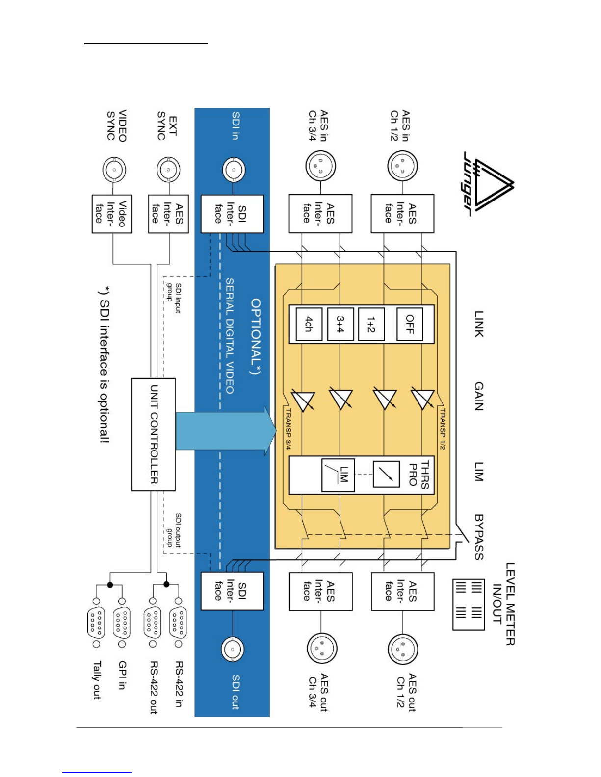
2.2
BLOCK DIAGRAM
Page 9

2. FUNCTION DESCRIPTION
operation manual b40, chapter 2 -Function description- page 2-3
All signal processing is done in the digital domain by Texas
Instruments floating point signal processors. The use of 32 bit word
length for calculation ensures that there is no deterioration in signal
quality, even if an audio signal with a maximum word length of 24 bit is
input into the processing of the unit.
GAIN means linear amplification of input or output signals. The input or
output gain can be changed in steps of 0.1 dB , within a range from -
15...+15 dB.
Adjustment of GAIN is channel independent.
The static characteristics of the b41 usually refers to a digital output
level of 0 dBFS (dB Full Scale). This is useful for most applications of
the dynamics processor as the on-following digital recording system is
supposed to be balanced down to the final bit.
For applications using headroom the output level of can be adjusted
within 0 ... -20 dBFS in steps of 0.1 dB. The limiter threshold
determines the maximum output level.
It is possible to choose one of four different programs for the
dynamics processor. Each provides ideal dynamics control for a
different kind of program signal as follows:
1 - universal
2 - classic
3 - pop music
4 - speech
Selecting a particular program sets up the optimum parameters of the
Limiter (attack and release times, threshold levels and interactions
between the multiple signal dependent control circuits) for a particular
kind of program material.
The time constants related to the transient response of the control
circuit are important for distortionfree processing. They are always
adaptively controlled. The algorithm has to guarantee best reaction for
fast increasing level of transient signals anytime even if classical music
with slow dying out characteristic is processed. In all cases the attack
time of the limiter for very short transients is zero.
The release time of the control circuit has influence to the increase of
loudness.
The selection of the parameter PROGRAM changes the range of time
constant values as follows:
PRO processing time corresponds to program
--------------------------------------------------------------------------------------------- 5 ms to 0.5 sec LIVE
15 ms to 1.2 sec SPEECH
30 ms to 2.5 sec POP
70 ms to 5.0 sec UNIVERSAL
50 ms to 8.0 sec CLASSIC
2.3
AUDIO SIGNAL
PROCESSING
2.3.1
GAIN
2.3.2
LIMITER
Theshold
2.3.3
PROGRAM
Page 10
2. FUNCTION DESCRIPTION
page 2-4 operation manual b40, chapter 2 -Function description-
The audio signal delay through the dynamics processor is approx.
2ms due to delaying of the audio signal using internal memory. A
small delay is deliberately introduced to the audio signal in order to
allow limiter and compressor algorithms which can 'preview' the audio
signal before changing it. That is the signal curve can be changed
before maximum level is reached. This delay must be considered
before attempting to mix signals processed by the dynamics
processor with other undelayed signals.
When mixing together a delayed signal and a direct signal there may
be cancellation of the signal waveform at some frequencies and reinforcement of the waveform at other frequencies (comb filter effect).
Corresponding 2ms delay of direct signals should therefore be carried
out before mixing them with delayed processed signals.
In case that the input signal (audio pair 1/2 or/and 3/4) is not audio (but
AC-3, Dolby E, MPEG..) the input can be feeded directly to the related
output bit transparent (no bit changes). The unit is switching to
transparent automatically if “non audio” flag in the Channel Status Bit of
the AES signal is set. Otherwise transparent mode can be set manually
by the user.
The digital audio limiter b41 is fitted with an serial remote interface in
RS-422 format.
Every device needs a device address to be registered in a remote
system. The address can be selected with the ADDR switch on the
rear panel. 16 addresses are selectable (0..F).
The changed address is valid with next power-on reset.
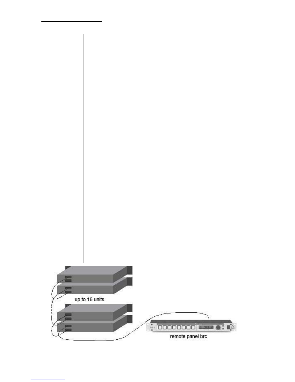
Up to 16 limiter b41 can be controlled from one remote panel.
Device model name and device address are to recognize using the
remote protocol of serial remote interface by an automation system or
by PC. With it various boxes can be combined in one remote system or
remote chain. However a maximum of 16 devices per model can be
controlled in one chain.
2.3.3.
INFLUENCE OF
SIGNAL DELAY
TIME
2.3.4
TRANSPARENT
MODE
2.4
REMOTE SYSTEM
Page 11

3. INSTALLATION
Operation manual b41, chapter 3 -installation- page 3-1
INSTALLATION
The digital audio limiter b41 was carefully packed in the factory
and the packaging was designed to protect the equipment from
rough handling. Please examine carefully the packaging and its
contents for any signs of physical damage, which may have
occured in transit.
The digital audio limiter b41 is a device under the safety
category Schutzklasse 1 in keeping with the VDE 0804
standards and may only used with power supply installations
built according to regulations.
Check the voltage details printed at the rear panel are the same
as your local mains electricity supply.
The digital audio limiter b41 is equipped with standard
connectors (see also chapter 3).
Before connecting the digital audio limiter b41 switch the power
off at all connected units.
The digital audio limiter b41 is made as standard 19“ unit (EIA
format). It occupies 1 RU (44 mm height) space in a rack.
Please allow at least additional 3“depth for the connectors on the
rear panel.
When installing the unit in a 19“ rack the rear side of the unit
needs some support, especially for mounting in flight cases.
The digital audio limiter b41 should not be installed near units
which produce strong magnetic fields or extreme heat. Do not
install the filter processor directly above or below power
amplifiers.
If, during operation, the sound is interrupted or displays no longer
illuminate, or if abnormal odor or smoke is detected immediately
disconnect the power cord plug and contact your dealer or
Jünger Audio.
3.1
UNPACK THE UNIT
3.2
POWER SUPPLY
3.3
CONNECTIONS
3.4
RACK MOUNTING
3.5
OPERATION
SAFETY
3
Page 12

3. INSTALLATION
page 3-2 Operation manual b41, chapter 3 -installation-
The digital audio limiter b41 has a digital signal output only. To
the problem-free combination of following digital devices, the
digital signal processing can be locked to an external clock
reference. The selection of the corresponding input is made in
the SYNC MODE menu. If the chosen sync input is connected
with the sync signal, this signal is used for synchronization
automatically. The digital output signal can be clocked with the
following clock frequencies:
CH 1/2 locks with the clock frequency of the input signal at
digital input CH 1/2 (AES/EBU, 48 kHz)
EXT SYNC locks with the clock frequency at the
external sync input (AES/EBU, 48 kHz)
VIDEO locks with the clock at the Video sync input
(internal 48 kHz)
SDI VIDEO locks with the clock at the SDI input
(internal 48 kHz)
Both digital outputs CH 1/2 and CH 3/4 are locked with same
clock frequency.
Note: SDI sync is available only if SDI interface is installed!
3.6
SYNCHRONIZATION
OF
DIGITAL OUTPUT
Page 13
3. INSTALLATION
Operation manual b41, chapter 3 -installation- page 3-3
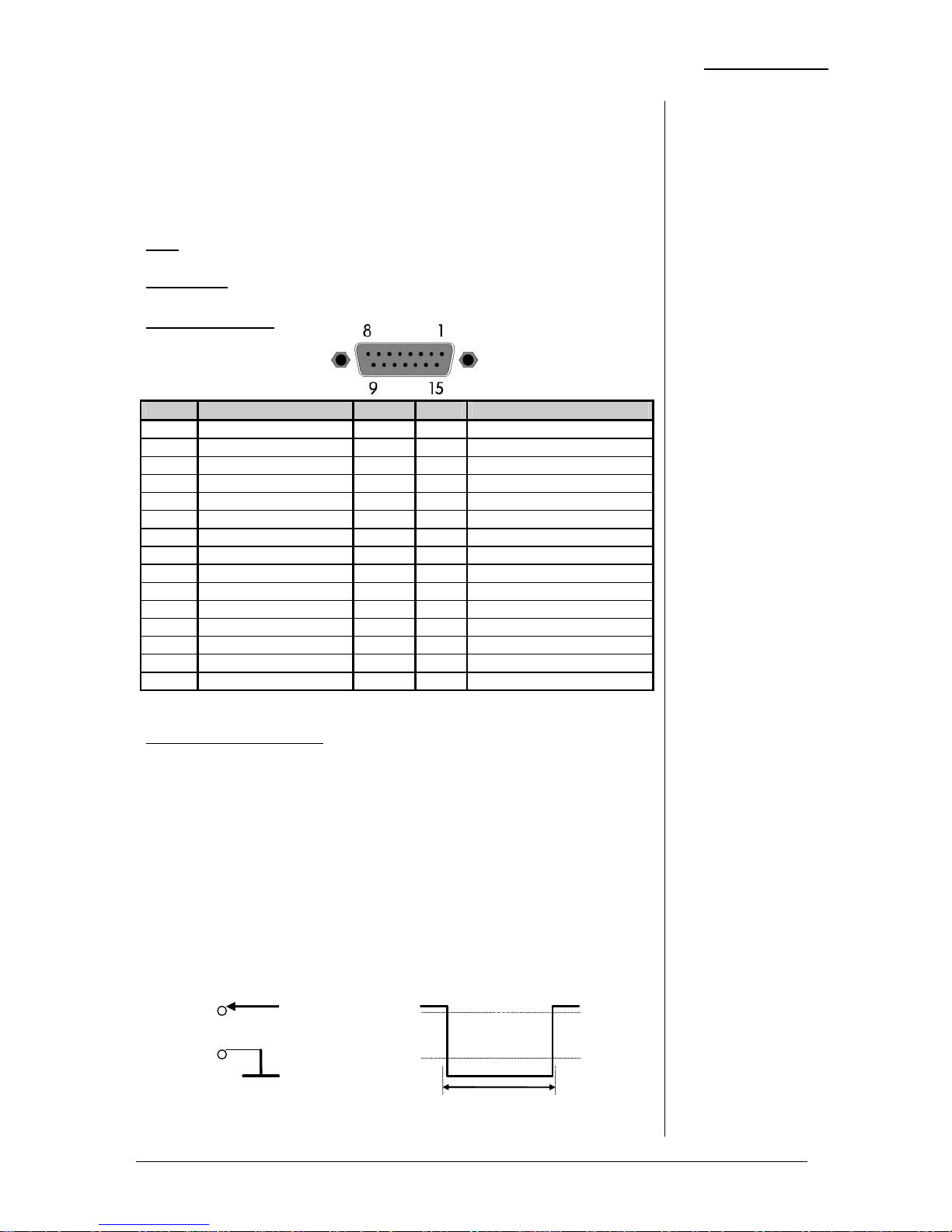
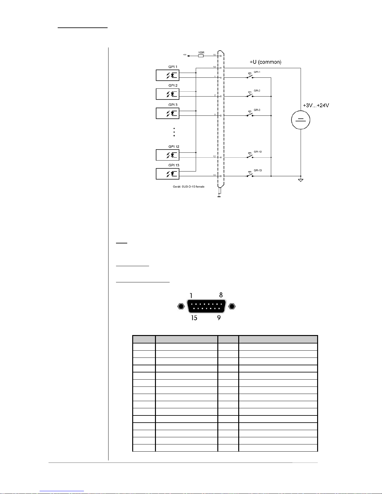
The digital audio limiter b41 can be remote-controlled by means
of parallel GPI contacts.
use : remote-controlled changeover of presets
connector: D-SUB 15pin, female
Pin assignments
Pin Signal name Logic I/O Functions
1 PRESET1 L I recall preset1
2 PRESET2 L I recall preset2
3 PRESET3 L I recall preset3
4 PRESET4 L I recall preset4
5 PRESET5 L I recall preset5
6 PRESET6 L I recall preset6
7 PRESET7 L I recall preset7
8 PRESET8 L I recall preset8
9 MUTE L I Muting outputs
10 BYPASS L I bypass on
11 not used
12 Phase rev ch1/2 L I
13 Phase rev ch3/4 L I
14 Common pin External voltage feed
15 +5V O Test power source
Ground on shield of the connector only!
Electrical specification:
GPI input potential free by opto-coupler, low active
OFF: +3.5…+30V between GPI input
and pin14
ON: less then 1.5V
Note: If using an external voltage feed it has to be connected to pin 14!
External Ground is switching the GPI on any of the inputs.
An internal voltage feed is available on pin 15. Ground is available from the
shield of the connector only! By using the internal voltage feed (connect PIN
14+15) there is no electrical isolation given anymore.
3.7
REMOTE
CONTROL
3.7.1
GPI REMOTE
CONTROL
(PARALLEL
REMOTE)
Pin1...13
Ext. voltage
feed+3
,
5...30V
Pin14
Contact to
ext. Ground
min. 50 ms
+1,5V
+3,5...30V
Page 14
3. INSTALLATION
page 3-4 Operation manual b41, chapter 3 -installation-
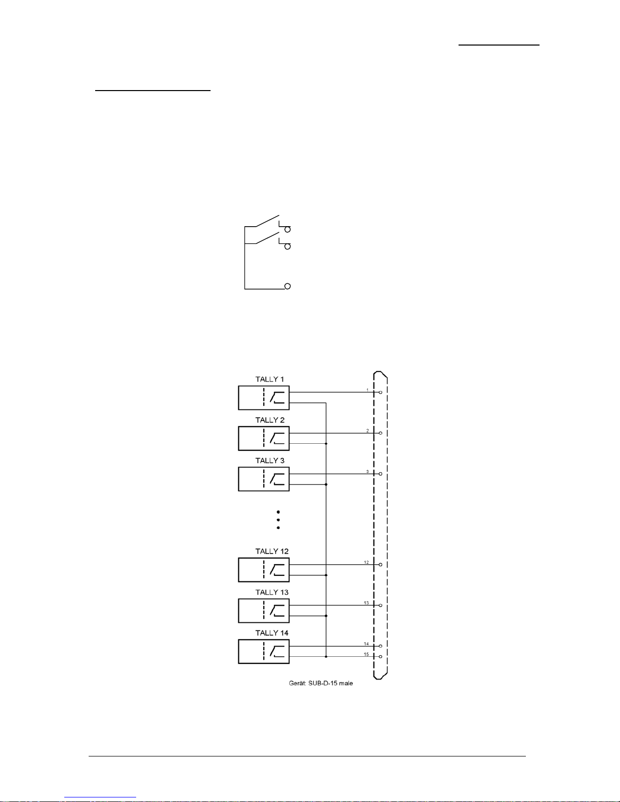
The digital audio limiter b41 can transmit specific device
statuses via parallel Tally lines.
use: Control of the remote-controlled changeover of
presets
connector: D-SUB 15pin, male
Pin assignments
Pin Signal name I/O Functions
1 T1 open contact O preset1 recalled
2 T2 open contact O preset2 recalled
3 T3 open contact O preset3 recalled
4 T4 open contact O preset4 recalled
5 T5 open contact O preset4 recalled
6 T6 open contact O preset4 recalled
7 T7 open contact O preset4 recalled
8 T8 open contact O preset4 recalled
9 T9 open contact O mute
10 T10 open contact O bypass
11 T11 open contact O Not used
12 T12 open contact O Not used
13 T13 open contact O Not used
14 T14 open contact O Not used
15 root Common root contact
3.7.2
TALLY OUT
Page 15
3. INSTALLATION
Operation manual b41, chapter 3 -installation- page 3-5
Electrical specification:
Tally output type: normally open relais contacts
Contact rating: 1A 24 VDC, 0,5 A 125 VAC
max. 30 W 62,5 VA
max. 60 VDC, 125 VAC
Pin1...14 Tally output
Open contact
Pin15 Common root
contact
Page 16
3. INSTALLATION
page 3-6 Operation manual b41, chapter 3 -installation-
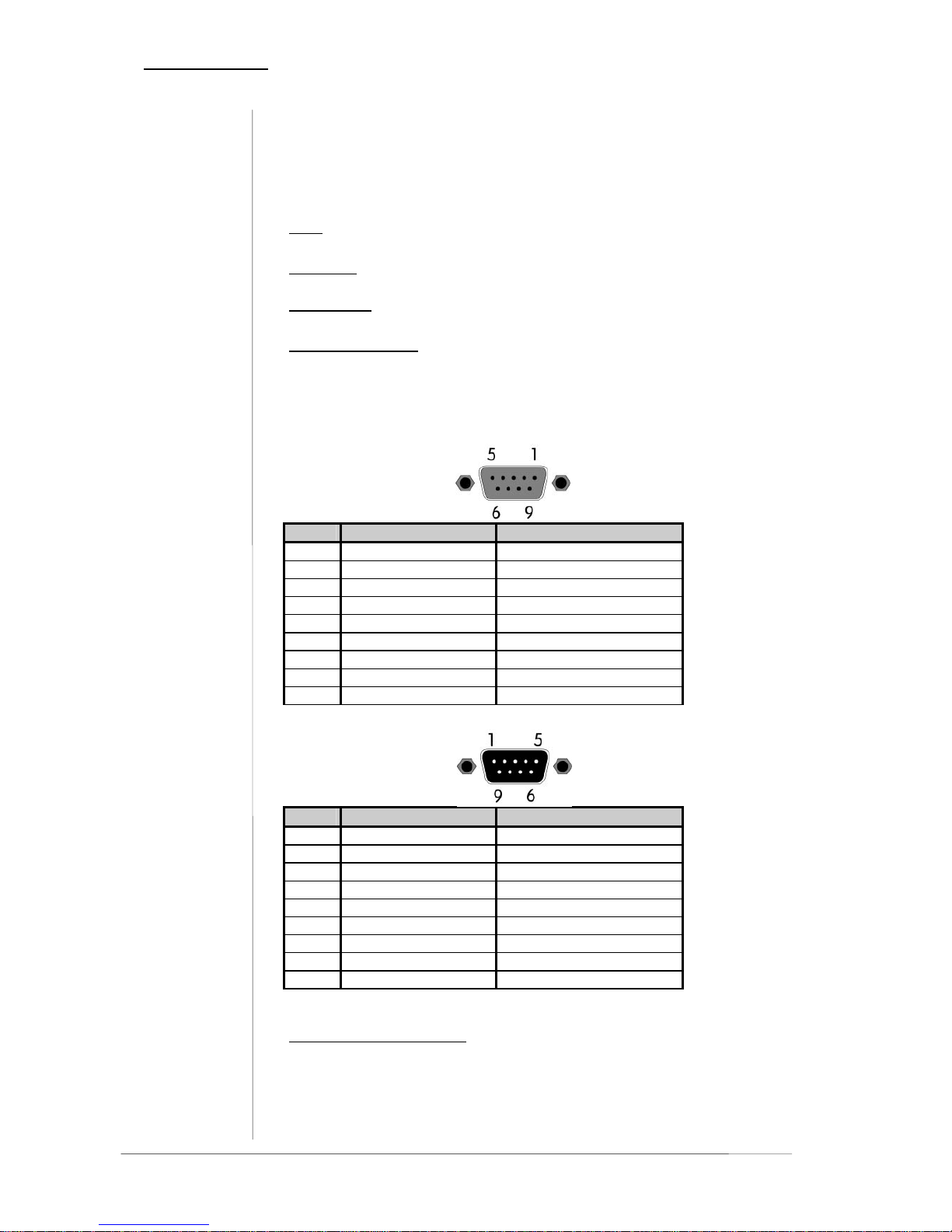
The digital audio limiter b41 can be remote-controlled by means
of serial remote RS-422.
use : remote-controlled changeover of presets
protocol:
available on request
connector: D-SUB 9pin, input - female
output - male
Pin assignments
The cable is wired 1:1 completely, the shield of the cable must be connected
on both ends!
REMOTE IN
Pin Signal name Functions
1 DSR + out Data set ready
2 DSR - out
3 SENSE in Interrogation Remote
4 RXD + out Receive data
5 RXD - out
6 DTR + in Data terminal ready
7 DTR - in
8 TXD + in Transmit data
9 TXD - in
REMOTE OUT
Pin Signal name Functions
1 DSR + in Data set ready
2 DSR - in
3 GND GND
4 RXD + in Receive data
5 RXD - in
6 DTR + out Data terminal ready
7 DTR - out
8 TXD + out Transmit data
9 TXD - out
Electrical specification:
signal in-/outputs TTL-level
3.7.3
SERIAL REMOTE
CONTROL
(RS-422)
Page 17
4. LOCATION OF PARTS AND CONTROLS
LOCATION OF PARTS AND
CONTROLS
4.1.
FRONT PANEL
4
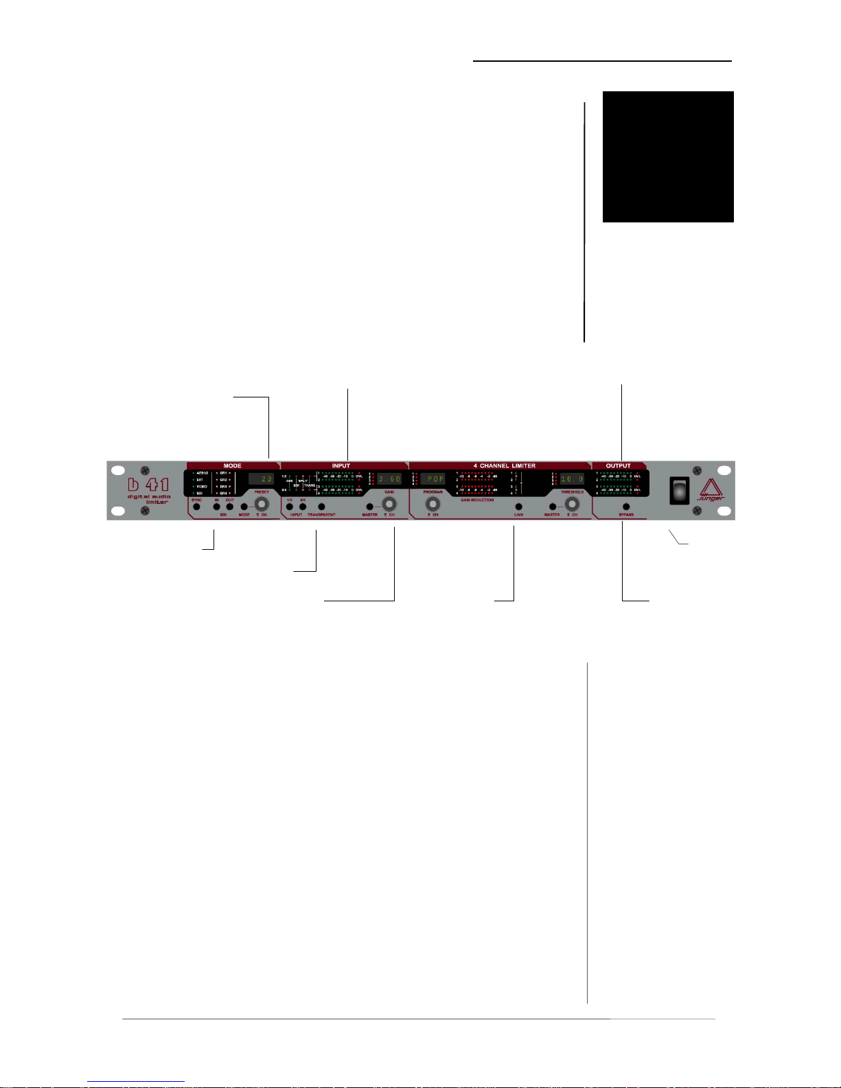
All control elements gives direct access.
In menu modes the alphanumeric display above the related
button or rotary knob is showing the specific function.
Preset selection
Output level
display
Input level
display
CONTROL
ELEMENTS
mode
input
Output
settings
Mains
switch
Sync selection
Input settings
Input gain Limiter
fig. 1: front panel b41
SYNC selection of sync input
IN / OUT group selection for SDI input/output
PREVIEW offline editing of presets
PRESET preset selection and administration
1/2 and 3/4 input selection AES / SDI
TRANSPARENT bit transparent mode for ch1/2 or ¾
Operation manual b41, chapter 4 -location of parts and controls- page 4-1
Page 18

4. LOCATION OF PARTS AND CONTROLS
input
MASTER ganging control knob for ch1…4
GAIN selection (push) and adjustment (turn)
of output gain
PROGRAM selection of limiter characteristic
limiter
LINK selection of channel link mode
THRESHOLD adjustment of limiter threshold
output
BYPASS switches bypass on and off
page 4-2 Operation manual b41, chapter 4 -location of parts and controls-
Page 19
4. LOCATION OF PARTS AND CONTROLS
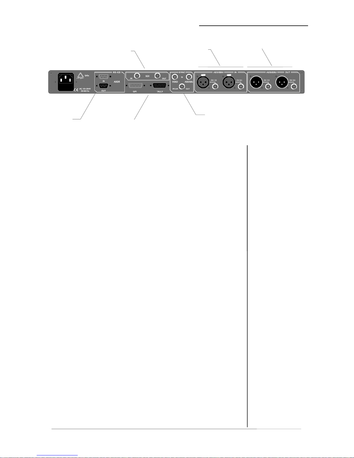
4.2.
REAR PANEL
SDI IN-/
OUTPUT
DIGITAL
INPUTS
DIGITAL
OUTPUTS
SYNC IN
SERIAL
REMOTE
IN/OUT
GPI REMOTE
IN/OUT
fig. 2: rear panel b41
POWER INPUT
IEC mains input connector 100-240V, 50/60 Hz with integrated fuse
REMOTE
serial remote interface RS-422
connector: 9pin SUB-D, input - female, output - male
GPI
paralle remote interface
TALLY-out open relais contact
connector: 15pin SUB-D, male
GPI-in +3,5…+30V potential-free
connector: 15pin SUB-D, female
SYNC
AES/EBU
input for ext. sync signal (AES 3 format, 75 Ohm, unbal)
connector: BNC socket
VIDEO
input for video sync signal (blackburst, 75 Ohm, unbal)
connector: BNC socket
W-CLOCK output for wordclock sync signal, TTL level, unbal.
connector: BNC socket
SDI IN / OUT (only if installed!)
Input/output for serial digital video (ITU-R BT.601, SMPTE 272M-A)
with embedded audio
Format: 270 Mb/s, 525/625 line rate, 75 Ohm,
connector: BNC socket
DIGITAL IN
input for AES/EBU standard format
connector: XLR female panel jack
1- ground, 2-3 signal, balanced
connector: BNC socket 75 Ohm, unbalanced
DIGITAL OUT
output for AES/EBU standard format
connector: XLR male panel jack
1- ground, 2-3 signal, balanced , 4 Vpp
connector: BNC socket 75 Ohm, unbalanced, 0.5V pp
Operation manual b41, chapter 4 -location of parts and controls- page 4-3
Page 20
4. LOCATION OF PARTS AND CONTROLS
4.3
SWITCHES AND
JUMPERS FOR
CONFIGURATION
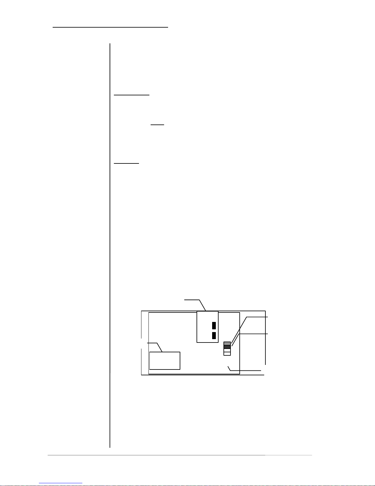
Some basic settings are to select by switches on the rear panel
or by switches and jumpers at the internal circuit boards of the
unit. These settings can occur general changes for operation
and should made by qualified engineering staff only.
Rear panel
Selection of the device address for serial
remote, 16 device addresses selectable
Note: Within a line of remote controlled units every
device needs a different address! The selected
address is valid after next power-on reset of the unit.
Internal
To set any internal jumper or switches it is necessary to open
the unit.
PLEASE DO NOT MAKE ANY ALTERATIONS WITH THE
MAINS STILL CONNECTED TO THE UNIT!
Loosen the screws on the top cover and remove. Then you can
see all jumper and switches as shown in the drawing below.
After setting of jumper or switches reassemble the unit in
opposite order.
Main board
SDI
Interface
J1
SDI Split
B4x
J2
Download
DSP card
page 4-4 Operation manual b41, chapter 4 -location of parts and controls-
Page 21
4. LOCATION OF PARTS AND CONTROLS
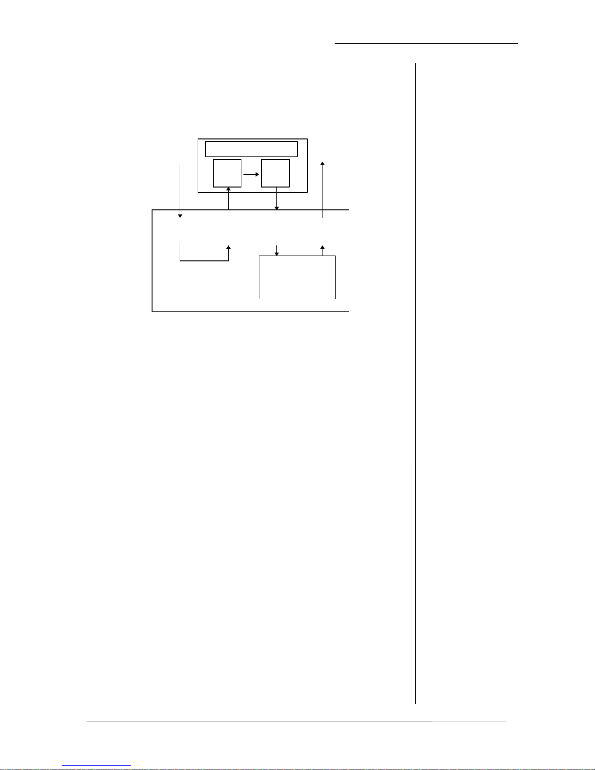
Units with SDI interface can be used in SDI split mode:
Audio in path SDI input > AES output
Audio out path SDI output > dsp processing > AES output
(see also 2.5)
dsp
processing
AES
out
SDI
out
SDI
in
B4x
Split Mode
AES
in
External device
AES
in
AES
out
The selection of split mode (SDI DIRECT) is made by setting
jumper J1 on main board of the unit.
The 4-channel processors of b40 series fitted with SDI-interface
are compatibel with the standard SMPTE 272M-AB. They
support 48 kHz synchronous audio sampling with 20 bit word
length.
4.4
SELECTION OF
SDI SPLIT MODE
4.5
CONFIGURATION
OF SDI INTERFACE
The standard allows up to four groups each of four mono audio channels.
(Usually used by most of D-VTR's and other equipment is Group 1 with 48
kHz synchronous sampling.)
Group selection and other settings are to configure with
switches on the SDI board as described following:
Operation manual b41, chapter 4 -location of parts and controls- page 4-5
Page 22

Page 23
5. OPERATION
OPERATION
5.0
DESCRIPTION OF
OPERATIONS
5
The use of the digital audio limiter b41 is very easy.
The setup or the programming of the digital audio toolbox b40 is
made by adjustment of various parameters and settings.
The description is made related to the functional blocks on the front
panel.
5.1 mode
5.2 recalling, saving and editing of presets
5.3 input selection
5.4 transparent mode
5.5 program
5.6 link
d 5.7 threshol
5.8 bypass
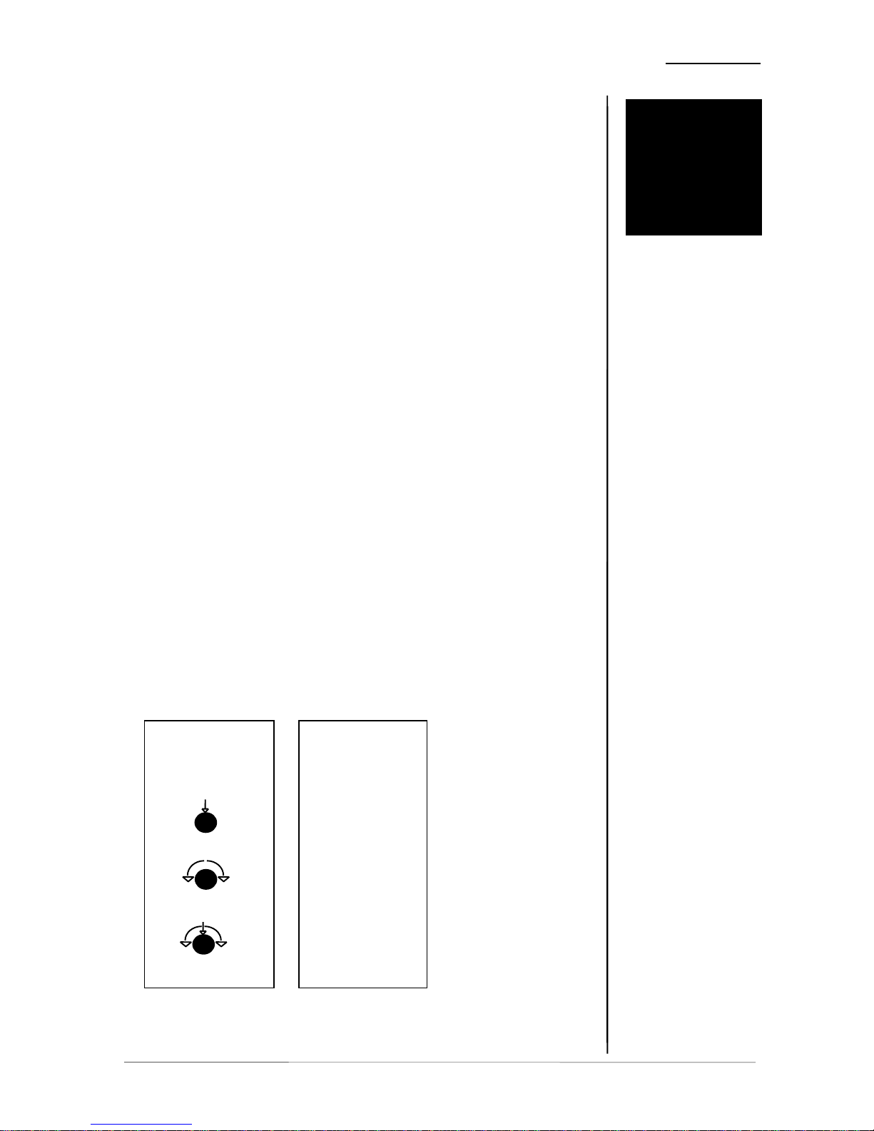
ollowing syntax is used: F
SYMBOL ACTIVITY
describes
how to use
button or
rotary knob
turn
p
ush + turn
p
ush
describes
action or function of
button or
rotary knob
operation manual b41, chapter 5 -Operation- page 5-1
Page 24
5. OPERATION
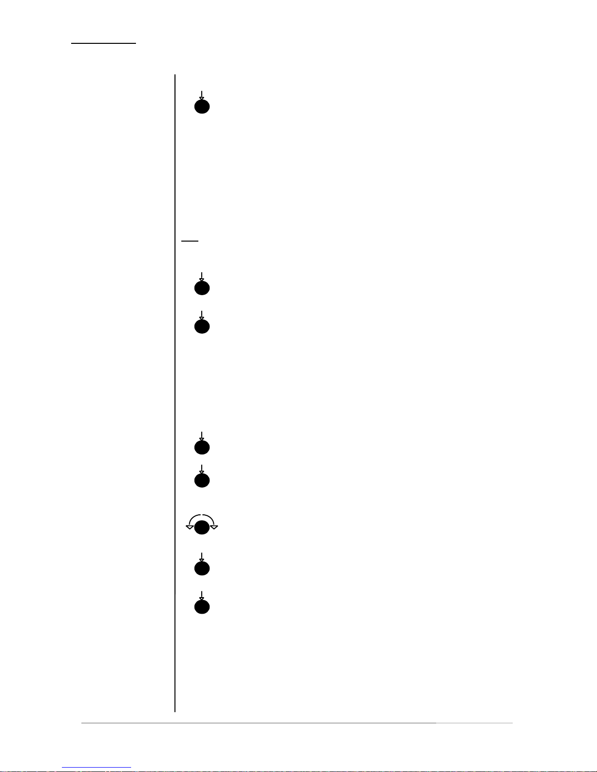
Selection of sync signal input
5.1
MODE
SYNC
selection of sync-signal input
1/2
unit is synchronized with AES input
channel 1/2 (AES 48kHz)
EXT
unit is synchronized with AES input
signal at external sync input
VIDEO unit is locked to video signal at video
input (with 48kHz)
SDI unit is locked to SDI signal at SDI
input (with 48kHz)
Note: SDI sync is available only if SDI input is active! If SDI sync is selected
only the SDI input LED lits. All LED’s in sync display are switched off!
Selection of group of audio for SDI signal
IN
SDI audio group selection for deembedder
and independent to that
OUT
SDI audio group selection for embedder
All adjusted parameters of TRANSP, DELAY, INPUT GAIN, MATRIX,
OUTPUT GAIN and FADE can be stored into presets.
Recall of presets
push
push
push
push
push
turn
5.2
RECALLING,
SAVING AND
EDITING OF
PRESETS
PREVIEW
until LOAD appears in the window.
PRESET
to enter preset load mode, “L” and
a blinking number 1..8 are to see
PRESET
to select the requested preset 1….8
PRESET
to load selected preset. The preset number
appears in the window.
push
push
or
PREVIEW
to exit without loading.
As soon as one of the in the preset stored parameter is changed
by manually operation a star symbol appears beside the number
in the window to show that the previously loaded preset is not
more present.
page 5-2 operation manual b41, chapter 5 -Operation-
Page 25
5. OPERATION
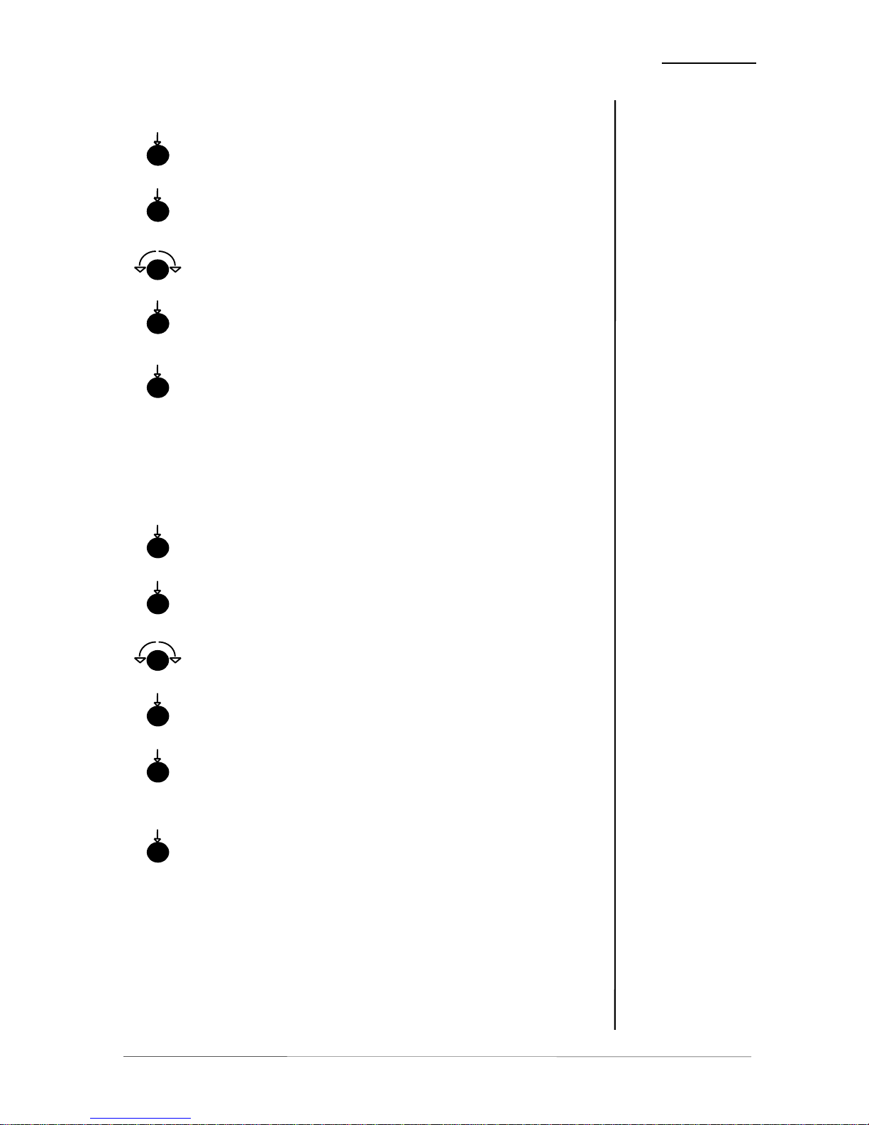
Storage of presets
PREVIEW
until SAVE appears in the window.
PRESET
to enter preset save mode, “S” and
a blinking number 1..8 are to see
PRESET
to select the preset 1….8 to save
PRESET
to save selected preset. The preset number
appears in the window.
or
PREVIEW
to exit without saving.
Note: All former stored preset values are overwritten at the moment of new
storage into this preset! Just as after initialization of the unit all presets are
overwritten with factory presets.
Editing of presets (PREVIEW mode, viewing and changing preset
content off-line without influencing running audio)
PREVIEW
until EDIT appears in the window.
PRESET
to enter preset edit mode, “E” and
a blinking number 1..8 are to see
PRESET
to select the preset 1….8 to edit
PRESET
to enter selected preset in edit mode
PRESET
to save back selected preset. The running
preset number appears in the window.
or
PREVIEW
to exit without saving.
Note: All former stored preset values are overwritten at the moment of new
storage into this preset! Just as after initialization of the unit all presets are
overwritten with factory presets.
turn
push
push
push
push
push
push
push
push
push
push
push
push
turn
operation manual b41, chapter 5 -Operation- page 5-3
Page 26
5. OPERATION
page 5-4 operation manual b41, chapter 5 -Operation-
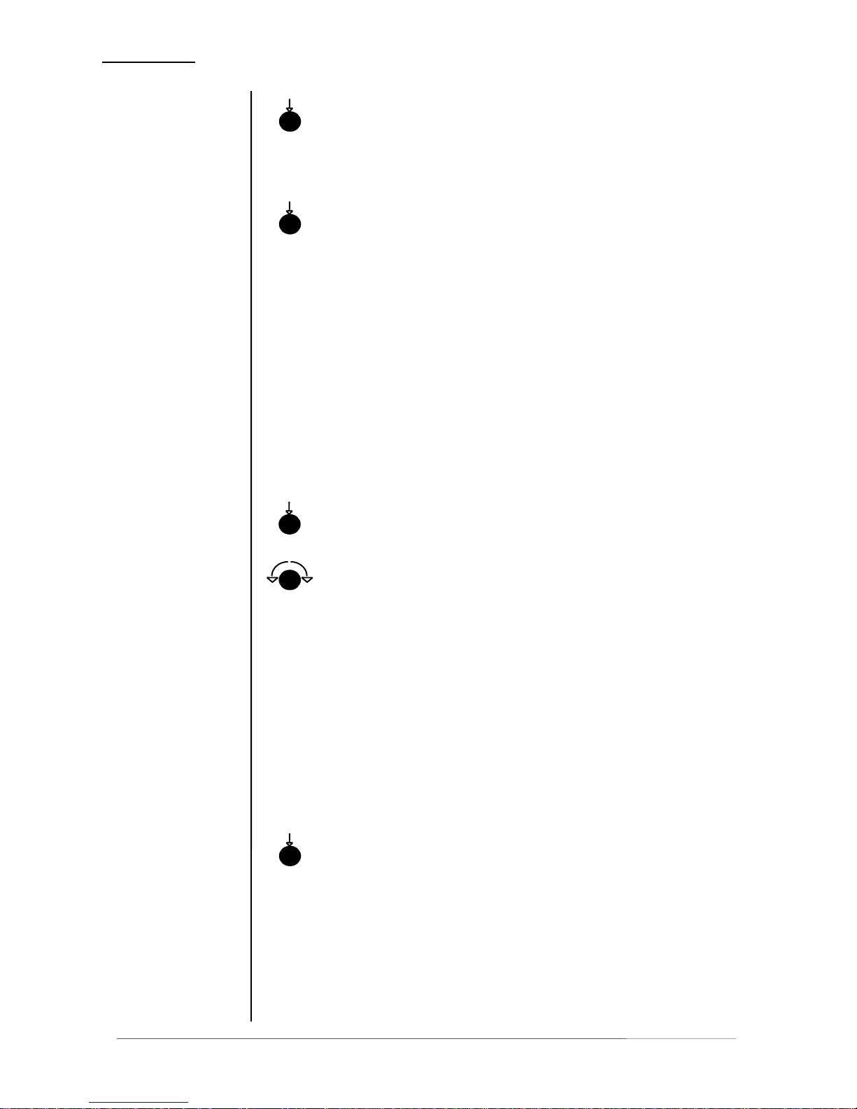
1/2 or 3/4 to switch for the input 1/2 or 3/4 between
5.3
INPUT
SELECTION
AES and SDI
push
5.4
TRANSPARENT
MODE
TRANSPARENT
to establish bit transparent connection
between input and output 1/2 or 3/4 or
push
1/2 and 3/4 (necessary to pass non-audio
bit streams through without changing)
5.5
PROGRAM
It is possible to choose one of different programs for the dynamics
processor. Each provides ideal dynamics control for a different kind of
programme signal as follows:
live, speech, pop music, universal, classic
Selecting a particular program sets up the optimum parameters of the
dynamics processor (attack and release times, threshold levels and
interactions between the multiple signal dependent control circuits) for
a particular kind of programme material.
Generally speaking, release times are longest when using the classical
setting and shortest when using the speech setting.
(In order to understand the basic Multi-loop principle of the Jünger Audio
dynamics processors please refer to chapter 6.1).
PROGRAM selection of channel
PROGRAM setting the program for the selected channel
push
turn
5.6
LINK
Coherent audio signals can be linked. The limiter reduction is done for
all linked channels with the same value determined by the channel
with highest audio level. Stereophonic and surround information or
even the panning between channels will not be changed for linked
channels.
Following links are possible:
CH1 + CH2 + CH3 + CH4 (all 4 channels linked)
CH1 + CH2 CH3 + CH4 (two pairs linked)
CH1 + CH2 CH3 CH4 (one pair linked)
CH1 CH2 CH3 + CH4 (one pair linked)
CH1 CH2 CH3 CH4 (all channels solo)
LINK selection of link mode
push
Page 27
5. OPERATION
5.7
THRESHOLD
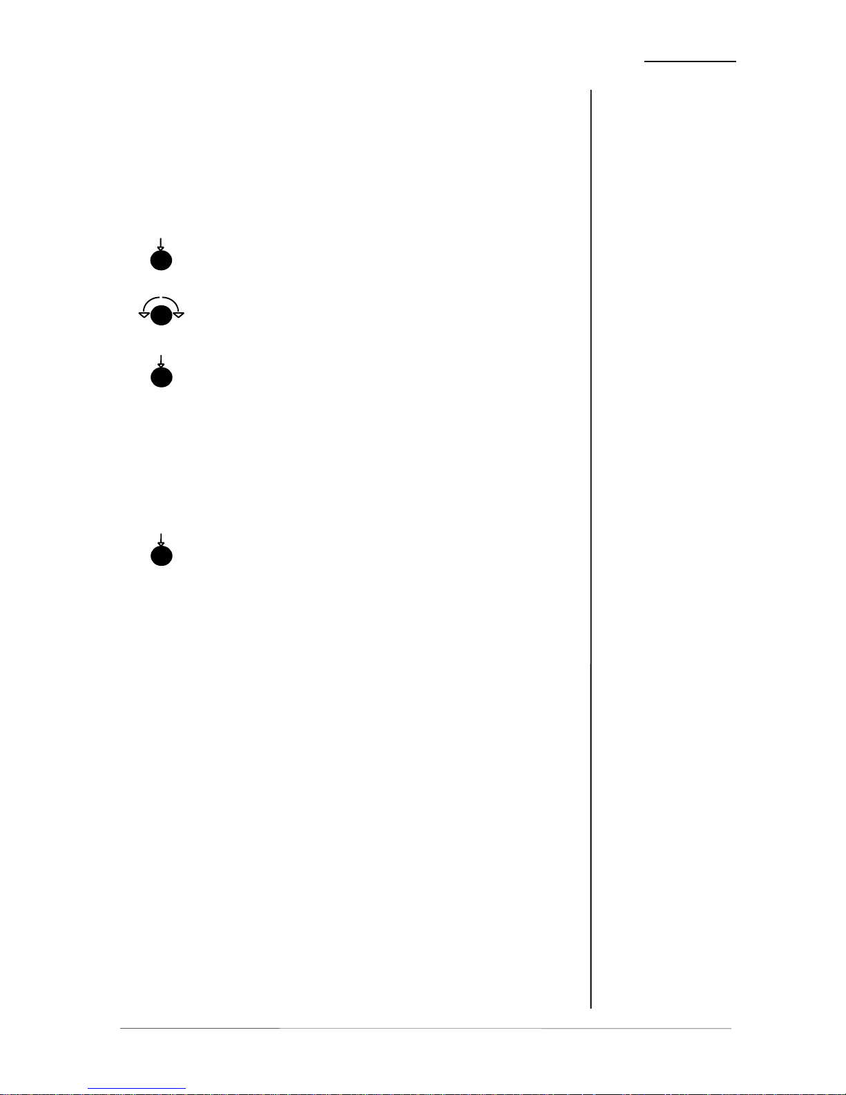
Limiter threshold level means maximum output level. The output level
will never be more than limiter threshold level. The limiter threshold
level can be changed in steps of 0.1 dB , within a range from -20...0
dBFS.
Adjustment of limiter threshold is channel independent if the channels
are not linked. Otherwise there is one threshold level only for all linked
channel.
PROGRAM selection of channel
PROGRAM setting the program for the selected channel
push
turn
MASTER to adjust all channels together
with the same value
push
5.8
BYPASS
BYPASS is bypassing the signal processing of the unit.
BYPASS is working for all configurations.
BYPASS switching bypass on or off
push
display: BYP. in the window
operation manual b41, chapter 5 -Operation- page 5-5
Page 28

Page 29
6. BOOT DISPLAY AND TROUBLE SHOOTING
BOOT DISPLAY AND
6.1
BOOT DISPLAY
6
T ROUBLE SHOOTING
display meaning / explanation
LIMITER display of processor model
B41 display of type
ADR. x display of unit address for serial remote control
6.2
ERROR
MESSAGES AND
TROUBLE
SHOOTING
display error / message remedies
NO SYNC no sync at sync input! ! connect the sync input
(selectable in SYNC field) with
valid input signal
# CH 1/2: sync on DIGITAL IN
CH 1/2
# EXT: sync on SYNC
AES/EBU
# VIDEO: sync on SYNC
VIDEO
# SDI: sync on SDI input
NO SDI! SDI input selected, no
valid SDI signal
received!
! check the availability of SDI
data stream
or
! select another input
Operation manual b41, chapter 6 -Boot display and trouble shooting- page 6-1
Page 30

6. BOOT DISPLAY AND TROUBLE SHOOTING
6.3
INITIALIZATION
THE UNIT
Should have remained the device no more operable and/or in the
program execution stand, recommends itself an initialization the
device.
During initialization, all storage areas important for the program
and registers are loaded with the factory setup and the program
is restarted.
Any button is to be held pressed in order to initialize the device
during switch-on of the device until the program started. To the
start of the program and at the completion of the displays (how
described in 6.1), the device is ready for operation with the
factory setup.
After an initialization of the device, all user presets and
adjustments are erased and/or overwritten by the factory
setup!
page 6-2 Operation manual b41, chapter 6 -Boot display and trouble shooting-
Page 31

7. APPLICATION NOTES
operation manual b41, chapter 7-Application notes- page 7-1
APPLICATION NOTES
In digital video recording technology four digital audio channels
are the standard configuration. This channel capacity is used
increasingly in production and post-production for surround
sound, providing mix options and for multi-lingual productions.
Quite often it is necessary to make corrections or changes to the
audio which until now required the use of an expensive digital
audio mixer. These tasks can now be easily solved with the
Jünger Audio range of digital audio toolboxes. Simple
processing for up to four digital audio signals may be carried out
quickly and efficiently.
Using the SDI versions (SDI=Serial Digital Interface, digital
component video format with 270Mb/s transmission) b40 series
can process embedded audio.
The standard allows up to four groups each of four mono audio
channels. Usually used by most of D-VTR's and other equipment
is Group 1 with 48 kHz synchronous sampling. Synchronous
means that the audio clock is genlocked to the associated video.
Each channel can have up to 20 bits of resolution per audio
sample.
The 4-channel processors of b40 series fitted with SDI-interface
are compatibel with the standard SMPTE 272M-AB. They
support 48 kHz synchronous audio sampling with 20 bit word
length.
The Jünger Audio SDI interface provides for one group of four
audio channels to be extracted from or inserted into the SDI data
stream. To address a specific channel group the group selection
is possible (see 4).
The b40 provides an optional SD- or HD-SDI board. When you
switch on the device the plugged in interface will be indicated in
the display
FEATURES
• Bypass relay for SDI IN >SDI OUT
• Bit transparent for coded data streams (e.g. DOLBYE/20bit)
• De-embedder: user selectable de-embedding of one group
• Embedder: user selectable embedding to one of 4 groups
• SDI-SYNC: SDI input can be the clock source of the device
• For HD-SDI: Multi-Format HD/SD operation with auto
detection
7.1
B40 SERIES WITH
SDI-INTERFACE
7
Page 32
7. APPLICATION NOTES
page 7-2 operation manual b41, chapter 7-Application notes-
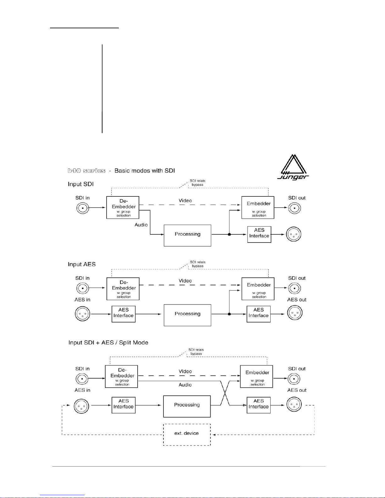
For the basic working mode the input of the digital audio
processing can be selected between AES/EBU or SDI (serial
digital video with embedded audio). The processed signals are
present at both outputs always - at AES/EBU and SDI.
There are two additional working modes using the SDI interface.
SDI Bypass is bypassing the SDI data stream. In this case only
extracted audio is processed and available at AES output. In Split
Mode the audio path is splitted. Embedded audio can be
processed with external equipment via AES interface.
Following illustration shows working modes:
7.2
BASIC WORKING
MODES WITH SDI
Page 33
7. APPLICATION NOTES
operation manual b41, chapter 7-Application notes- page 7-3
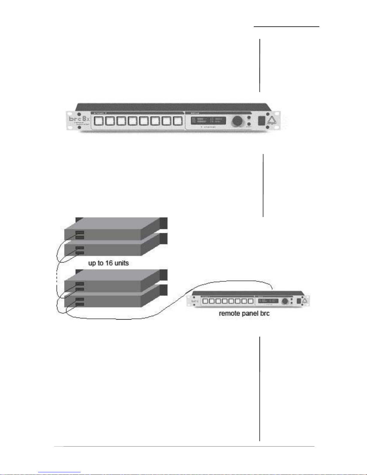
The Digital Audio Limiter b41 can be used remote controlled by
the programmable remote control panel brc.
All settings of the b41 toolbox can be made on the front panel of
the box or via the edit menus of brc remote control.
Working with the brc remote control panel means rapid changes
of preprogrammed presets by pushing one button only.
features of brc:
- universal remote control panel (RS-422)
- remote operation of several units (up to 16 devices from B40
series 2nd generation)
- remote panel is detecting connected units
- remote control panel brc8x as programmable
control unit with "one touch" access of presets
by hot keys
- 19" case, 1RU, only 75 mm depth!
7.3
REMOTE CONTROL
WITH BRC
Fig . 8.1: programmable remote control brc
Fig . 8.2: installation with remote control brc
Page 34

Page 35

8. TECHNICAL SPECIFICATIONS
operation manual b41, chapter 8-Technical specifications- page 8-1
TECHNICAL
SPECIFICATIONS
sample rate : 48 kHz
audio data format : 24 bit (AES/EBU), 20 bit (SDI)
DIGITAL IN/OUT
AES/EBU
connector : XLR,110 Ohm, balanced
BNC, 75 Ohm, coaxial
input format : AES professional, AES consumer
output format : same as input format
SDI (only for SDI version)
connector : BNC, 75 Ohm, coaxial
data rate : 270 Mb/s, 525/625 Line rate
format : serial digital component video 4:2:2
with embedded audio
(ITU-R BT.601, SMPTE 272M-A)
level: 800 mV +/- 10%
equalisation : appr. 180 m (Belden 8281)
audio data: 4 channels, 20 bit
features : SDI relais bypass
independent group selection for
de-embedder and embedder
SDI (only for SDI version)
SD-SDI
VIDEO :
standard: SMPTE 272 M–A, 270 Mbit SD-SDI
connection: BNC, 75 Ohm, coaxial
signal level: 800mV ±10%
equalisation: 300m (Belden 8281 , 270 MHz)
return loss: >15 dB
supported video standards:
SD 525/59.94 SMPTE 125M
SD 625/50 SMPTE 125M
digital signal
processing
digital
in- / outputs
SDI
in- / output
8
Page 36

8. TECHNICAL SPECIFICATIONS
page 8-2 operation manual b41, chapter 8-Technical specifications-
AUDIO :
audio data format : 20 Bit, transparent for C-Bit and U-Bit according to
AES3
audio sample rate : 48 kHz synchronous to video-carrier
latency : (deembedder + embedder)
SD : < 2,6 msec
GENERAL :
power supply : +5V DC
consumption : approx. 500 mA
dimension : 3RU, 4HP, 160mm depth (EUROPA size pcb)
temperature : 10°C to 40°C
humidity : 90%, non condensing
HD-SDI
technical specifications
VIDEO :
standard: SMPTE 299M 1,485 Gbit HD-SDI
SMPTE 272M–A, C 270 Mbit SD-SDI
connection: BNC, 75 Ohm, coaxial
signal level: 800mV ±10%
equalisation: 130m (Belden 1694A, 1.485GHz)
300m (Belden 8281 , 270 MHz)
return loss: >15 dB (1.485 GHz)
supported video standards:
HD 720/60 SMPTE 296M HD 1080/25 SMPTE 274M
HD 720/50 SMPTE 296M HD 1080/24 SMPTE 274M
HD 720/30 SMPTE 296M HD 1080/50 SMPTE 295M
HD 720/25 SMPTE 296M HD 1035/60 SMPTE 260M
HD 720/24 SMPTE 296M
HD 1080/60 SMPTE 274M SD 525/59.94 SMPTE 125M
HD 1080/50 SMPTE 274M SD 625/50 SMPTE 125M
HD 1080/30 SMPTE 274M
all HD-standards are supported also with their 1/1001-frame-rates
AUDIO :
audio data format : 24 Bit, transparent for C-Bit and U-Bit according to
AES3
audio sample rate : 48 kHz synchronous to video-carrier (SD and HD)
32 kHz ... 48 kHz asynchronous to video-carrier (HD
only)
latency : (deembedder + embedder)
HD : < 800µsec
SD : < 2,6 msec
GENERAL :
power supply : +5V DC
consumption : approx. 1.000 mA
dimension : 3RU, 4HP, 160mm depth (EUROPA size pcb)
temperature : 10°C to 40°C
humidity: 90%, non condensing
Page 37

8. TECHNICAL SPECIFICATIONS
operation manual b41, chapter 8-Technical specifications- page 8-3
SYNC IN
AES/EBU
connector : BNC, 75 Ohm, coaxial
level : 0,5 ... 5 Vpp
input format : AES professional, AES consumer
VIDEO
connector : BNC, 75 Ohm, coaxial
level : 0...1 Vpp
input format : Blackburst or PAL/NTSC composite video
REMOTE
serial remote interface RS-422 in/out
level : TTL
connector : 9 pin SUB-D male/female
GPI parallel remote
level : +3…+30V, H-active, optocoupler
connector : 15 pin SUB-D female
Tally Out level : normally closed relais contacts
Contact rating: 1A 24 VDC, 0,5 A 125 VAC
max. 30 W 62,5 VA
max. 60 VDC, 125 VAC
connector : 15 pin SUB-D male
GENERAL
power consumption : appr. 15 VA
dimensions : 19“, 1 RU, 250 mm depth
weight : appr. 5 kg
optional : programmable remote control brc
sync
in- / outputs
remote control
Page 38

9. WARRANTY AND SERVICE INFORMATION
operation manual b41, chapter 9 -Warranty and service information- page 9-1
WARRANTY AND SERVICE
INFORMATION
JÜNGER AUDIO grants a two-year warranty on the
4-channel digital audio limiter b41
If the unit has to be serviced, please send it
ideally in the original box, to:
JÜNGER AUDIO - Studiotechnik GmbH
Justus-von-Liebig-Str. 7
D - 12489 Berlin
GERMANY
Tel.: (*49) -30-677721-0
Fax.: (*49) -30-677721-46
9
Page 39

Geräteart : 4ch digital toolbox
Type of equipment : 4ch digital toolbox
Produkt / Product : b41
Das bezeichnete Produkt stimmt mit den Vorschriften folgender EU-Richtlinie(n) überein:
The aforementioned product complies with the following Europaen Council Directive(s):
89/336/EWG (geändert durch 91/263/EWG und 92/31/EWG)
(changed by 91/263/EEC and 92/31/EEC)
Richtlinie der Rates zur Angleichung der Rechtsvorschriften der
Mitgliedsstaaten über die elektromagnetische Verträglichkeit
Council Directive on the approximation of the laws of the
Member States relating to electromagnetic compatibility
73/23/EWG (geändert durch 93/68/EWG)
(changed by 93/68/EEC)
Richtlinie des Rates vom 19. Februar 1973 betreffend elektrische
Betriebsmittel zur Verwendung innerhalb bestimmter
Spannungsgrenzen
Council Directive of February 19th 1973 concerning electircal
equipment for operation within certain voltage limits
Zur vollständigen Einhaltung dieser Richtlinie(n) wurden folgende Normen herangezogen:
To fully comply with this(these) Directive(s), the following standards have been used:
EN 55022 : 1987
EN 50082-1 : 1993
EN 60065 : 2002
Dieser Erklärung liegen zugrunde : Prüfbericht(e) des EMV-Prüflabors
Interne Vorschriften zur Sicherheits-Prüfung
This certification is based on : Test report(s) generated by EMC-test laboratory
Internal regulations for safety check
MEB Messelektronik Berlin : Kalibrier- und Prüflabor
accredited EMC laboratory
Aussteller / Holder of certificate : Jünger Audio Studiotechnik GmbH
Justus-von-Liebig-Strasse 7
D - 12489 Berlin
Berlin, 18.03.2003 .....................................................................................
(Ort/Place) (Datum/Date) (Herbert Jünger, Geschäftsführer/Managing Director)
KONFORMITÄTSERKLÄRUNG
DECLARATION OF CONFORMITY
Page 40
 Loading...