

Page 1
ZigBee radio transmitter module 4-gang
ZigBee radio transmitter module 4-gang
Art. No. : ZLLCD5004M
ZigBee radio transmitter module 4-gang
Art. No. : ZLLLS5004M
ZigBee radio transmitter module 4-gang
Art. No. : ZLLA5004M
Operating instructions
1 Safety instructions
Electrical devices may only be mounted and connected by electrically skilled
persons.
Serious injuries, fire or property damage possible. Please read and follow manual fully.
Keep button cells out of reach of children! If button cells are swallowed, get medical help
immediately.
Risk of explosion! Do not throw batteries into fire.
Risk of explosion! Do not recharge batteries.
These instructions are an integral part of the product, and must remain with the end
customer.
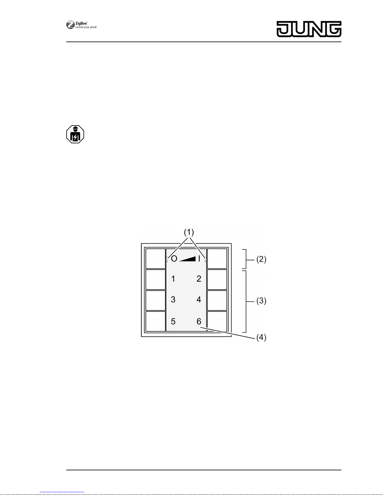
Device components
Figure 1
(1) LED
The LED of the respective side of the button lights up green as long as the button is
pressed.
When the functions "Individually set luminaires" or "Service functions" are active, both
LEDs light up red.
During commissioning, the LEDs indicate the status of the functions, see Chapter 4.
(2) Buttons for switching/dimming
(3) Scene buttons/functional buttons
(4) Cover
Intended use
- ZigBee Light Link transmitter for operation of participants conforming with ZigBee Light
Link, e.g. lamps, luminaires, light bands, ballast units, adapters
1/17
32596203
J0082596203
23.05.2016
Page 2
- The transmitter can cooperate with ZigBee Light Link devices or systems of other
manufacturers, e.g. Philips Hue or Osram Lightify.
- Surface-mounted installation in interior areas
i Hereinafter, the participants will be called luminaires.
Product characteristics
- Supports the adjustment of: brightness, colour temperature, light colour and colour
saturation
- Corresponds with the ZigBee Light Link specification
- Saving and recalling of up to 6 scenes
- Status indication with LED
- Battery-powered device
- Software update using separate additional device via radio possible
Insert battery
WARNING!
Risk of chemical burns.
Batteries can burst and leak.
Replace batteries only with an identical or equivalent type.
o Carefully remove cover (4) from wall transmitter .
i Keep contacts of batteries and device free of grease.
o Observe polarity: The positive pole of the battery must be at the top.
o Apply battery to the positive contact of the battery holder and lock in place with little
pressure.
o Snap on the cover (4).
2 Basic functions
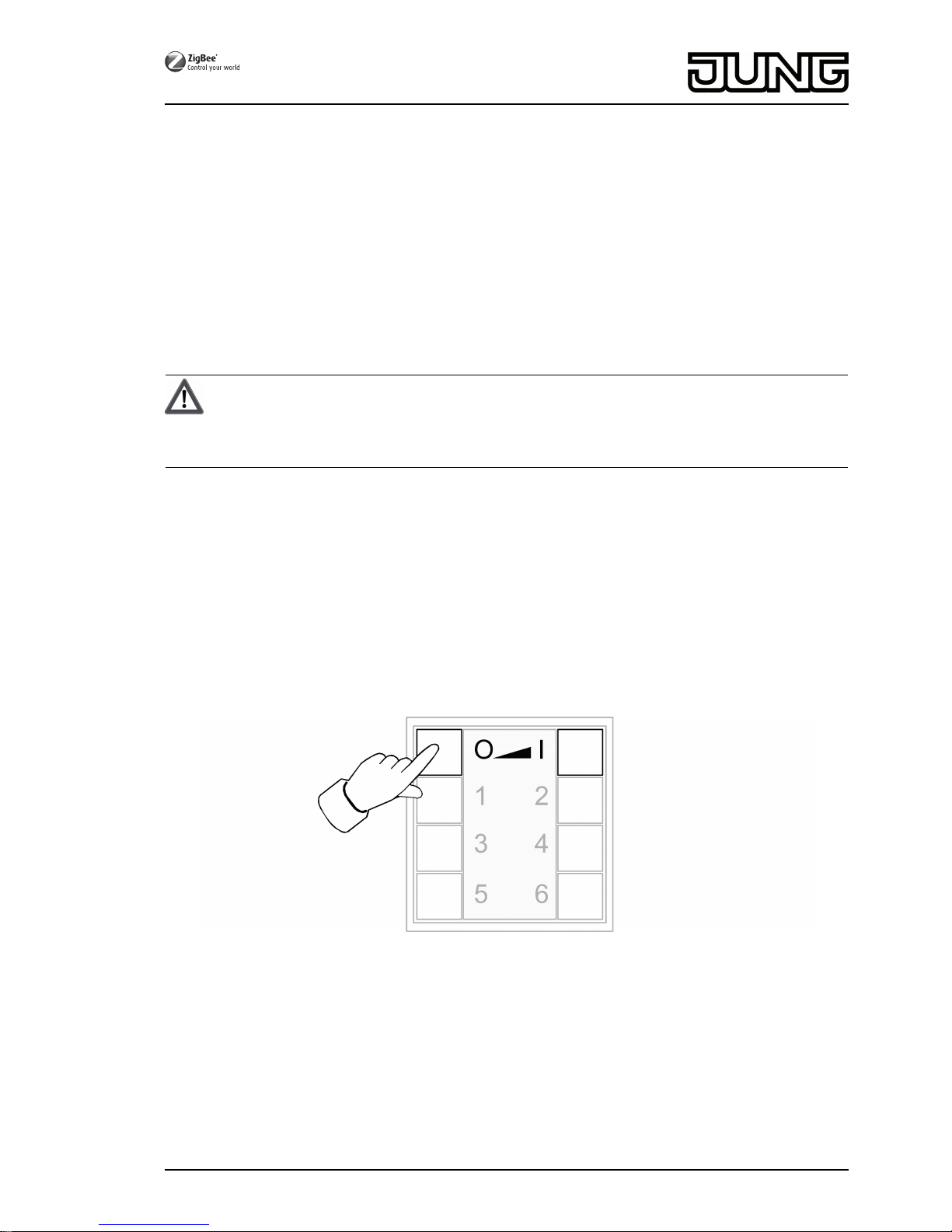
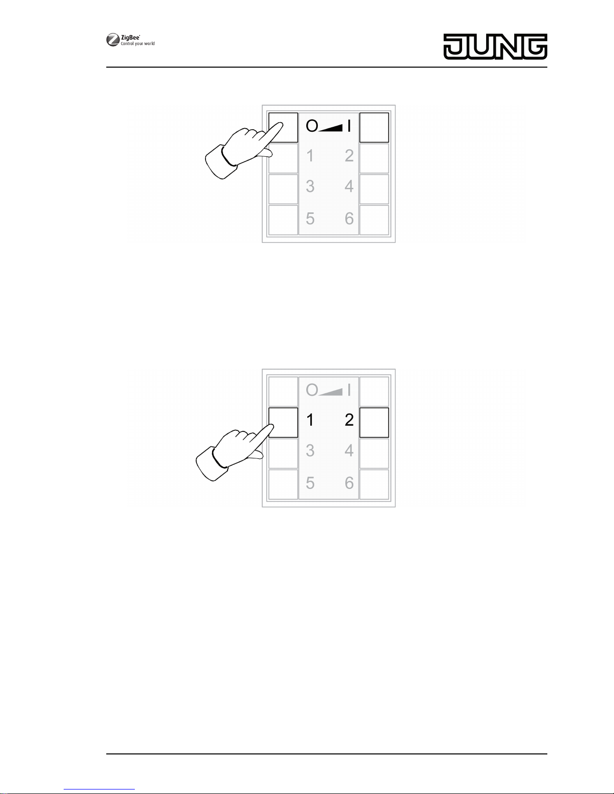
2.1 Switching or dimming luminaires
i All luminaires connected to the transmitter will be collectively switched or dimmed.
Figure 2
o Switch: Short press on Ɔ or ƍ button.
o Dim: Long press on Ɔ the or ƍ button. The dimming process ends when the button
is released.
2.2 Recalling scenes
Scenes help you to save individual settings of one or more persons and to recall them with a
single press of a button.
2/17
32596203
J0082596203
23.05.2016
ZigBee radio transmitter module 4-gang
Page 3
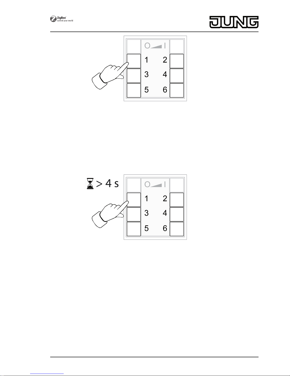
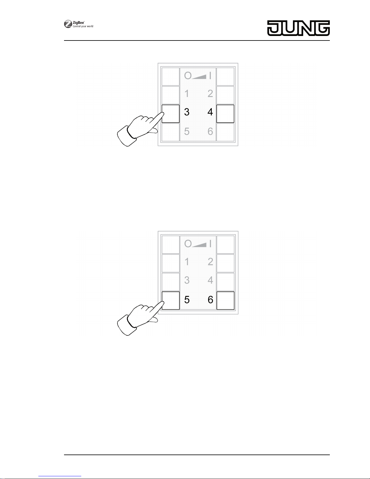
Figure 3
o Press the corresponding scene button Ƈ briefly until ƌ.
The luminaires that belong to that scene will switch to the saved values.
2.3 Saving scenes
i If the scene shall be recalled from several transmitters, it must be saved at each transmitter
separately.
o Luminaires that shall not be part of the scene must be disconnected prior to saving.
o Set the luminaires to the desired values, see chapter 3.
Figure 4
o Press the corresponding scene button Ƈ to ƌ for longer than 4 seconds.
The LED on the respective side of the button lights up green for 3 seconds. The scene has
been saved on the selected button.
3/17
32596203
J0082596203
23.05.2016
ZigBee radio transmitter module 4-gang
Page 4
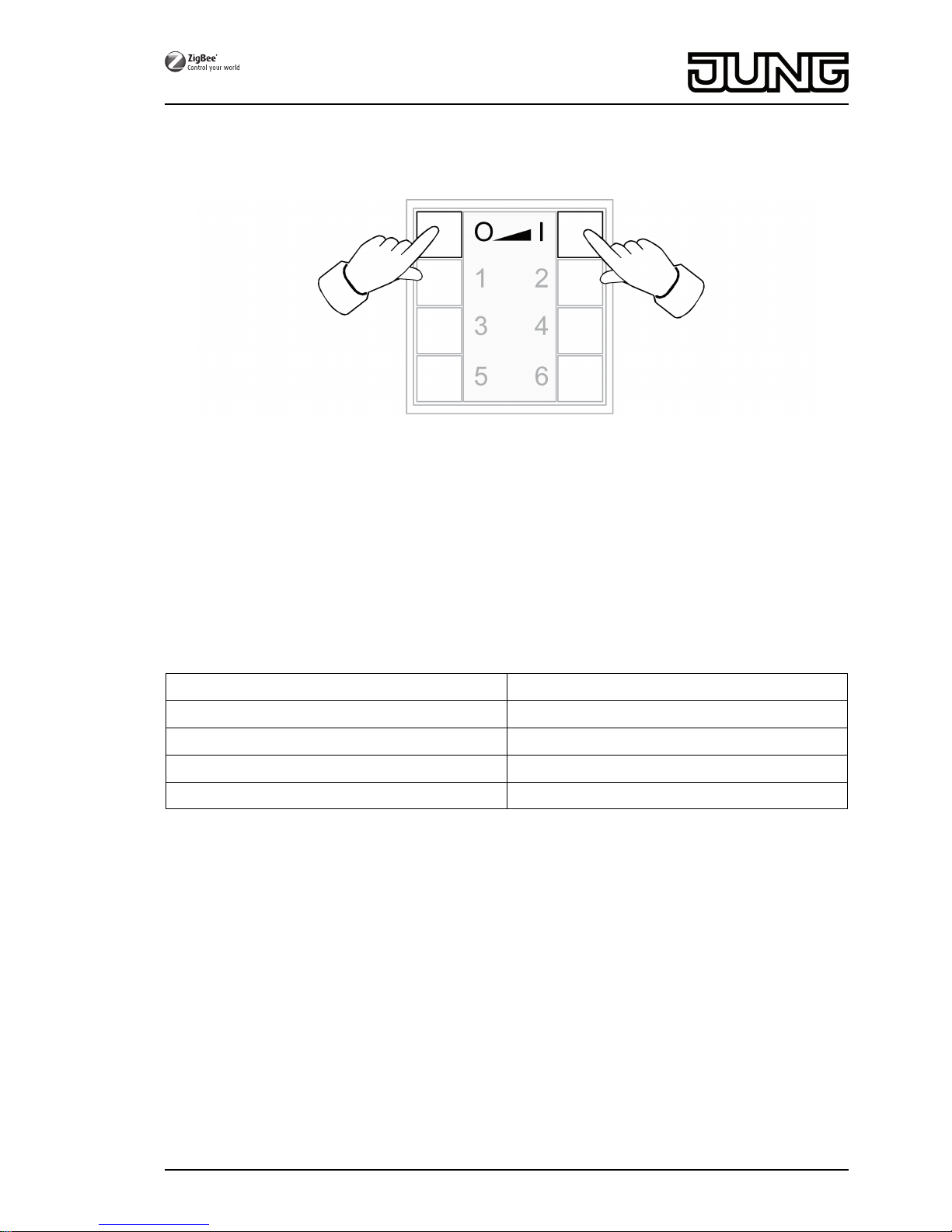
3 Setting luminaires individually
3.1 Selecting a luminaire
Figure 5
o Simultaneously press the Ɔ and ƍ buttons shortly.
Both LEDs light up red.
All luminaires that are connected to the transmitter are selected. The luminaires
acknowledge this by e.g. short flashing.
i If only a single luminaire shall be set, press the Ɔ and ƍ buttons simultaneously
until the respective luminaire is selected. When the last luminaire connected to the
transmitter has been selected, all luminaires connected to the transmitter will be selected
upon the next press.
o Switch on the luminaire by shortly pressing the ƍ button.
o Set the luminaire. The available settings depend on the luminaire used.
Luminaire selection Ɔ and ƍ
Switching and brightness Ɔ or ƍ
Light colour Ƈ or ƈ
Colour saturation Ɖ or Ɗ
Colour temperature Ƌ or ƌ
o Wait for approx. 6 seconds until the transmitter switches back the basic functions.
o As an option, save the settings as a scene, see chapter 2.3.
4/17
32596203
J0082596203
23.05.2016
ZigBee radio transmitter module 4-gang
Page 5
3.2 Switching or dimming luminaires individually
Figure 6
o Select a luminaire, see chapter 3.1.
o Switch: Short press on Ɔ or ƍ button.
o Dim: Long press on Ɔ the or ƍ button. The dimming process ends when the button
is released.
3.3 Setting the light colour
Figure 7
o Select a luminaire, see chapter 3.1.
o Setting a predefined colour: press the Ƈ or ƈ button shortly until the desired light
colour is set.
o Setting an individual light colour: press the Ƈ or ƈ button until the desired light
colour is set.
Depending on the current light colour, the colour changes towards the next predefined
colour.
5/17
32596203
J0082596203
23.05.2016
ZigBee radio transmitter module 4-gang
Page 6
3.4 Setting the colour saturation
Figure 8
o Select a luminaire, see chapter 3.1.
o Setting white: shortly press Ɖ.
o Setting the maximum colour saturation: shortly press Ɗ.
o Setting individual colour saturations: press the Ɖ or Ɗ button until the desired colour
saturation is set.
3.5 Setting colour temperature
Figure 9
o Select a luminaire, see chapter 3.1.
o Setting warm white: shortly press the Ƌ button.
The colour temperature is set to approx. 2700 K, which is typical for light bulbs.
o Setting cold white: shortly press the ƌ button.
The colour temperature is set to approx. 4500 K, which is typical for fluorescent lamps.
o Setting individual colour temperatures: hold the Ƌ or ƌ button until the desired
colour temperature is set.
The colour temperature increases or decreases to the respective final value that the
luminaire supports.
6/17
32596203
J0082596203
23.05.2016
ZigBee radio transmitter module 4-gang
Page 7

4 Commissioning
4.1 Basic commissioning procedure
Preconditions:
During commissioning, the respective devices must have a distance of 10 to 50 cm to each
other.
Each device can only be part of one network.
The luminaire shall be operated using a Philips Hue Bridge or an Osram Lightify Gateway
and transmitters.
o Commission the luminaire with a bridge or gateway.
o Add the transmitter to the network of the bridge or gateway.
i If the transmitter already belongs to a network, reset the transmitter beforehand, see
Chapter 4.6.
i The procedure depends on the app used and may deviate from the procedure described
herein. Up-to-date information can be found on our website.
o Open the network of the bridge or gateway.
Philips Hue Bridge Osram Lightify Gateway
Start Philips Hue app. Start Osram Lightify app.
Select "Settings". Select "Devices".
Select "My lamps" Press "+".
Select "Connect new lights". Select "Add lights/plugs".
Select "Automatic search". Press "→".
o Press the Ƌ and ƍ buttons on the new transmitter simultaneously until the LEDs
flash green.
i After approx. 10 seconds the transmitter searches for an open network.
LEDs light up green for 3 seconds. The transmitter has joined the network of the bridge or
gateway.
LEDs flash red quickly for 10 seconds. The transmitter has not joined the network.
o Connect the transmitter to a luminaire, see Chapter 4.2.
The luminaire shall exclusively be operated using a transmitter without connection to a
Philips Hue Bridge or Osram Lightify Gateway.
The luminaire has default settings.
o Connect the luminaire to a transmitter, see chapter 4.2.
or the luminaire belongs to another network.
o Reset luminaire, see chapter 4.5.
o Connect the luminaire to a transmitter, see chapter 4.2.
i For additional luminaires, repeat the corresponding actions.
The luminaire should be operated with several transmitters without a connection to a
Philips Hue Bridge or Osram Lightify Gateway
Precondition:
The luminaire is already connected to a transmitter, see chapter 4.2.
o Add a new transmitter to the network, see chapter 4.3.
o Connect the luminaire to the new transmitter, see chapter 4.2.
7/17
32596203
J0082596203
23.05.2016
ZigBee radio transmitter module 4-gang
Page 8

4.2 Connecting a luminaire to a transmitter
Figure 10
o Press the Ɔ and ƌ buttons simultaneously until the LEDs flash green.
The luminaire flashes briefly. Connection in process.
LEDs on transmitter light up green. Lamp lights up green or flashes twice. Connection has
been set up successfully.
LEDs on transmitter flash red quickly for 3 seconds. Could not set up connection.
i In case of error, the distance between the devices is too big or the luminaire already
belongs to an existing network, see chapter 4.5.
Alternatively, all memory locations in the transmitter are occupied. In this case, delete all
connections to luminaires that are no needed, see chapter 4.6.
4.3 Adding the transmitter to an existing network
i If the transmitter already had belonged to a network, reset the transmitter, see chapter 4.7.
Figure 11
Precondition:
At least one luminaire must be switched on.
o Press the Ƌ and ƍ buttons on the new transmitter simultaneously until the LEDs
flash green.
The new transmitter is in programming mode.
8/17
32596203
J0082596203
23.05.2016
ZigBee radio transmitter module 4-gang
Page 9

o Within 10 seconds. start a connection process on a transmitter from the existing network
(see chapter 4.2 or the manual of the respective transmitter).
i After 10 seconds, if no connection process is started, the transmitter will search an open
network in order to join it.
LEDs light up green for 3 seconds. Transmitter has been added to a network.
LEDs flash red quickly for 10 seconds. Transmitter has not been added to a network.
4.4 Cloning the transmitter
All connections of a transmitter will be transferred to another transmitter. This function can only
be used with our transmitters.
o Add a new transmitter to the network, see chapter 4.3.
Figure 12
Precondition:
At least one luminaire must be switched on.
o Press the Ƌ and ƍ buttons on the new transmitter simultaneously until the LEDs
flash green.
The new transmitter is in programming mode.
o Within 10 seconds, start a connection process on the transmitter to be cloned, see
chapter 4.2.
LEDs light up green for 3 seconds. The new transmitter has accepted the connection.
LEDs flash red quickly for 10 seconds. The new transmitter has not accepted a connection.
4.5 Resetting a luminaire
All connections of the luminaire will be disconnected and the allocation to a network will be
deleted.
i If several luminaires are mounted near to each other, it might be necessary to disconnect
those luminaires from the mains that are not supposed to be reset.
9/17
32596203
J0082596203
23.05.2016
ZigBee radio transmitter module 4-gang
Page 10

Figure 13
o Keep the Ƈ and ƈ buttons pressed until the LEDs flash green.
Lamp flashes: Reset in progress.
LEDs light up green; lamp lights up. Resetting successful.
LEDs flash red quickly for 3 seconds. Participant could not be reset.
4.6 Deleting connections from the transmitter to the luminaires
i The transmitter can save a maximum of 10 connections to luminaires. If the memory is full,
a connection needs to be deleted first in order to be able to save a new connection.
Figure 14
o Press Ɔ and ƍ buttons simultaneously and briefly until the connection to be deleted
is selected.
LEDs light up red. All connections to luminaires are selected.
o Press the Ɔ and ƍ buttons simultaneously and briefly until the connection to be
deleted is selected.
The corresponding luminaire flashes.
i If the corresponding luminaire is defective or does not exist any more, press the Ɔ or
ƍ buttons simultaneously until to luminaire flashes after pressing. The transmitter will
indicate this by an LED flashing in red.
o Press the Ƈ and ƈ buttons simultaneously for longer than 4 seconds.
LEDs light up green for 3 seconds. The connection has been deleted from the transmitter.
10/17
32596203
J0082596203
23.05.2016
ZigBee radio transmitter module 4-gang
Page 11

4.7 Resetting the transmitter to the default setting
i All connections to luminaires will be disconnected and the allocation to a network will be
deleted.
Figure 15
o Keep the Ɖ and Ɗ buttons pressed.
After approx. 10 seconds, the LEDs flash green.
o Release the Ɖ and Ɗ buttons and press the Ɔ button within 10 seconds.
Transmitter will be reset to the default settings. After completion, the LEDs light up green
for 3 seconds.
5 Service functions
5.1 Switching on the service functions
The service functions can exclusively be used with our transmitters. They enable you for
example to connect fixed wall transmitters to luminaires when these cannot be brought into
connection range to each other or to pass on existing connections from one transmitter to
another.
Precondition:
To be able to use the service functions (switch them on) the transmitter must be part of the
network, see chapter 4.3 and at least one luminaire must be switched on.
o Keep the transmitter within a range of 10 to 50 cm from the luminaire or transmitter.
11/17
32596203
J0082596203
23.05.2016
ZigBee radio transmitter module 4-gang
Page 12

Figure 16
o Switch on the service functions. To do so, shortly press the Ƌ and ƌ buttons.
LEDs light up red. The service functions have been switched on.
o Save luminaires or connections in the buffer memory of the transmitter, see chapter 5.2,
5.3 or 5.4.
o Pass on luminaires or connections to a transmitter, see chapter 5.5.
i By pressing the above buttons again or after 2 minutes without action the service functions
are switched off and the buffer memory is deleted.
5.2 Seizing selected luminaires
Figure 17
o Switch on the service functions, see chapter 5.1.
o Press the Ɔ and ƌ buttons simultaneously until the LEDs flash green.
LEDs light up green for 3 seconds: The connection to the luminaire is saved in the buffer
memory. The transmitter waits for further connections.
LEDs flash red quickly for 3 seconds: The connection to the luminaire has not been saved
in the buffer memory. The transmitter waits for further connections.
o As an option, save further connections in the buffer memory. To do so repeat the previous
step.
o As an option, press the Ɔ button shortly in order to show all luminaires in the buffer
memory.
12/17
32596203
J0082596203
23.05.2016
ZigBee radio transmitter module 4-gang
Page 13

The luminaires saved in the buffer memory light up shortly.
o Within 2 minutes, after the last button has been pressed, transfer the buffer memory to the
desired transmitter, see chapter 5.5.
5.3 Accepting connections from another transmitter
Figure 18
o Switch on the service functions, see chapter 5.1.
o On the receiving transmitter, press the ƍ and Ƌ buttons simultaneously until the
LEDs flash green.
o Start a connection process on the transmitter to be read out, see Chapter 4.2.
LEDs light up green for 3 seconds. The connections from the transmitter to be read have
been saved in the buffer memory.
LEDs flash red quickly for 3 seconds. The connections from the transmitter to be read have
not been saved in the buffer memory.
o As an option, press the Ɔ button shortly in order to show all luminaires in the buffer
memory.
The luminaires saved in the buffer memory light up shortly.
o Within 2 minutes, after the last button has been pressed, transfer the buffer memory to the
desired transmitter, see chapter 5.5.
5.4 Copy the transmitter connections that are saved in the transmitter to the buffer
memory
Figure 19
13/17
32596203
J0082596203
23.05.2016
ZigBee radio transmitter module 4-gang
Page 14

o Switch on the service functions, see chapter 5.1.
o Press the Ƈ button for longer than 4 seconds.
LEDs light up green for 3 seconds. The connections have been saved in the buffer
memory.
o As an option, press the Ɔ button shortly in order to show all luminaires in the buffer
memory.
The luminaires saved in the buffer memory light up shortly.
o Within 2 minutes, after the last button has been pressed, transfer the buffer memory to the
desired transmitter, see chapter 5.5.
5.5 Passing connections from the buffer memory to a transmitter
o Put the receiving transmitter in programming mode, see chapter 4.3.
Figure 20
o Start a connection process on the sending transmitter by pressing the Ɔ and ƌ
buttons simultaneously until the LEDs flash green.
The connections are passed from the buffer memory to the receiving transmitter.
LEDs light up green for 3 seconds. The connections from the buffer memory are passed
on.
LEDs flash red quickly for 3 seconds. The connections from the buffer memory have not
been passed on.
6 Updating device software
The device software is updated via radio. This requires a separately available additional device.
Refer to the manual of the additional module.
Precondition 1:
The additional device must belong to the network of the transmitter.
Precondition 2:
The transmitter must not be in default.
14/17
32596203
J0082596203
23.05.2016
ZigBee radio transmitter module 4-gang
Page 15

Figure 21
o Press the Ƌ and ƍ buttons simultaneously until the LEDs flash green.
After 10 seconds the LEDs flash green quickly: The transmitter searches for an update.
The LEDs flash red: Update in process.
The LEDs flash green for 3 seconds: Update successful.
The LEDs flash red quickly for 10 seconds: Update not successful.
i In order to cancel the update, press any button.
7 Mounting
Precondition: To ensure good transmission quality, keep a sufficient distance from any possible
sources of interference, e.g. metallic surfaces, microwave ovens, hi-fi and TV systems, ballasts
or transformers.
i Perform commissioning procedures before installation (see chapter Commissioning).
Figure 22
o Change the battery (see chapter Changing the battery).
o Screw or glue the base plate (5) to an even surface. The TOP/OBEN label has to be at the
top.
o Position the design frame (7) on the base plate.
15/17
32596203
J0082596203
23.05.2016
ZigBee radio transmitter module 4-gang
Page 16

o Screw wall transmitter module (8) to base plate.
i Screwing the screws too tightly could impair functions of the wall transmitter.
o Snap on the buttons (11)(figure 22).
Information on gluing mounting
Precondition: To be able to fasten the wall transmitter safely, the surface must be flat and free
of dust and grease.
o Remove the rear, unpunched film of the enclosed adhesive pad.
o Align the adhesive pad, stick it to the surface and smooth it out. Remove air bubbles.
o Remove the two inner segments of the front film.
o Align the base plate to the external punching and stick it on.
i In the case of multiple combinations, the abutting sides of the adhesive pads must be cut
along the external punching using a ruler and a cutter (figure 23).
Figure 23: Cutting the adhesive pads for multiple combinations
i If necessary, after mounting the wall transmitter in the CD program, carefully remove the
excess adhesive film in the corners.
8 Appendix
Remove empty batteries immediately and dispose of in an environmentally friendly
manner. Do not throw batteries into household waste. Consult your local authorities
about environmentally friendly disposal. According to statutory provisions, the end
consumer is obligated to return used batteries.
8.1 Technical data
Rated voltage DC 3V
Battery type 1×Lithium CR 2450N
Ambient temperature -5 ... +45°C
Relative humidity max. 80% (No moisture condensation)
Storage/transport temperature -25 ... +70°C
Degree of protection IP 20
Protection class III
Number of connections max. 10
Transmitting range in free field typ. 100m
Radio frequency 2.400 ... 2.483GHz
Transmission capacity < 10mW
16/17
32596203
J0082596203
23.05.2016
ZigBee radio transmitter module 4-gang
Page 17

8.2 Troubleshooting
Removing a luminaire from a scene
Cause: a luminaire has not been disconnected from the mains when a scene was saved which
it is not supposed to belong to.
Reset the lamp and connect it to the transmitter again, see Chapter 4.2
Luminaire cannot be connected to transmitter, LEDs on transmitter flash red.
The luminaire is already part of another network.
Reset the luminaire, see chapter 4.5 and start another connection process, see
chapter 4.2.
The LED does not light up when a button is pressed.
Battery in the transmitter is empty.
Change the battery, see Inserting a battery.
8.3 Accessories
Cover kit 4-gang Art. No. ..504TSA..
8.4 Conformity
Albrecht Jung GmbH & Co. KG hereby declares that the radio system type
Art. No. ZLLCD5004M / ZLLLS5004M / ZLLA5004M
corresponds to the directive 2014/53/EU. You can find the full article number on the device. The
complete text of the EU Declaration of Conformity is available under the Internet address:
www.jung.de/ce
8.5 Warranty
The warranty follows about the specialty store in between the legal framework as provided for
by law.
ALBRECHT JUNG GMBH & CO. KG
Volmestraße 1
58579 Schalksmühle
GERMANY
Telefon: +49 2355 806-0
Telefax: +49 2355 806-204
kundencenter@jung.de
www.jung.de
17/17
32596203
J0082596203
23.05.2016
ZigBee radio transmitter module 4-gang
 Loading...