

Page 1
System control unit
System control unit 1-channel
Art.-No.: WL 2200 REG
System control unit 2-channel
Art.-No.: WL 2200-2 REG
Operationsmanual
1 Safety instructions
Electrical equipment may only be installed and fitted by electrically skilled persons.
Failure to observe the instructions may cause damage to the device and result in fire and
other hazards.
Danger of electric shock. Device is not suitable for disconnection from supply voltage.
Danger of electric shock. Always disconnect before carrying out work on the devise or
load. At the same time, take into account all circuit breakers that supply dangerous
voltage to the device or load.
These instructions are an integral part of the product, and must remain with the end
customer.
2 Device components
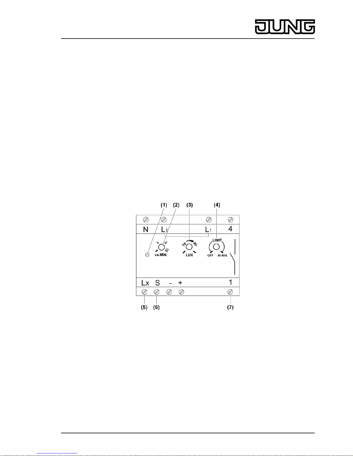
System power pack, 1-channel RMD
picture 1: Power pack, 1-channel
(1) Status LED
(2) Adjuster, run-on time, MIN
(3) Adjuster, brightness threshold, LUX
(4) Forced switch-off adjuster, LIMIT
(5) Terminal Lx Brightness evaluation of the system sensor
(6) Terminal S Signal evaluation of the system sensor
(7) Terminals 1 and 4 Potential-free switching contact
1/7
32508313
J:0082508313
09.08.2010
Page 2
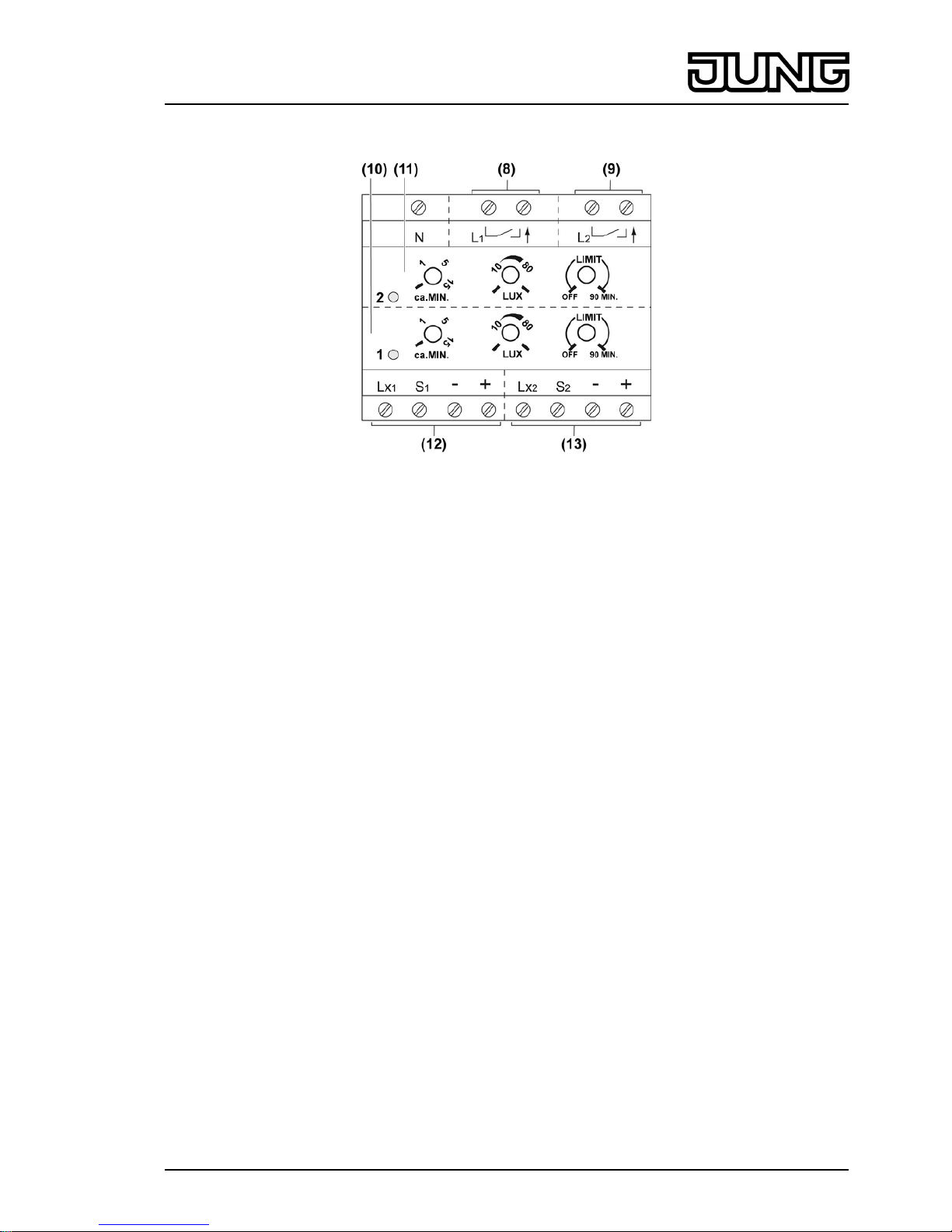
System power pack, 2-channel RMD
picture 2: Power pack, 2-channel
(8) Switching contact, channel 1
(9) Switching contact, channel 2
(10) Channel 1: Status LED and adjuster for MIN, LUX and LIMIT
(11) Channel 2: Status LED and adjuster for MIN, LUX and LIMIT
(12) Connection of system sensors for Channel 1
(13) Connection of system sensors for Channel 2
3 Function
Intended use
- Switching of electrical loads for the duration of a settable time on not reaching a brightness
threshold
- Operation with suitable system sensors
- Installation in distribution boxes on DIN rail according to DIN EN 60715
Product characteristics
System power pack, 1-channel RMD
- Device reacts to motion detection of system sensors
- Brightness threshold settable
- Switch-on time settable
- Forced switch-on settable, limit function
- Potential-free NO contact
- Small voltage switchable
- Manual switch-on possible with installation button, NC contact
System power pack, 2-channel RMD
- Device reacts to motion detection of system sensors
- Brightness threshold can be set separately for both channels
- Switch-on time can be set separately for both channels
- Forced switch-off can be set separately for both channels
- Channel 1: non-floating NO contact
- Channel 2: potential-free NO contact
- Manual switch-on of both channels possible with installation button, NC contact
2/7
32508313
J:0082508313
09.08.2010
System control unit
Page 3
Automatic operation
System sensors (accessories) detect heat movements or people, animals or objects and
forward movement signals and the current brightness value to the power pack.
- The light is switched on if a person enters the monitored detection area and the brightness
is below the set threshold.
- The light is switched off if no more movement is detected in the detection area and the
follow-up time has elapsed.
In order to avoid light oscillations due to the cooling of a bulb, the power pack does not evaluate
any signals for approx. 3 seconds after switch-off.
Switching on the mains voltage of the power pack triggers a switching operation on the power
pack.
The Status LED (1) of the appropriate channel lights up when the load is switched on.
4 Operation
Switching the light on manually
Optional installation button, NC contact is installed (mounting and electrical connection).
o Press the installation button for at least 1 second.
Light is switched on independently of the brightness for the set follow-up time.
When motions are detected, the delay time is restarted.
Configuring the power pack
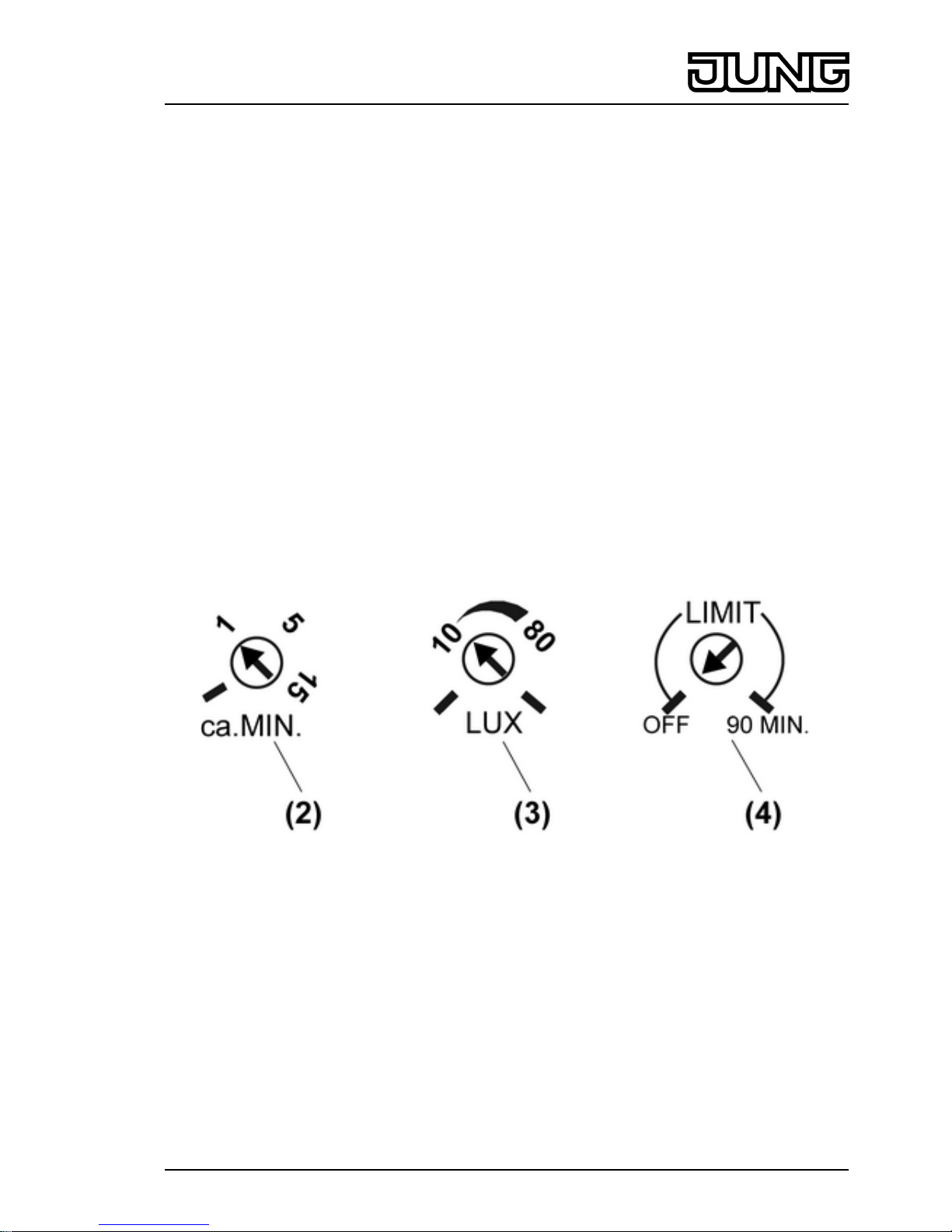
The three adjusters can be used to set the run-on time, the brightness threshold and, if
necessary, a forced switch-off after 90 minutes.
picture 3: Power pack adjuster
Set follow-up time
The light remains switched on for this time after the last movement detection. The run-on time is
set between approx. 4 seconds and 15 minutes.
o Turn the MIN adjuster (2) to the required position (picture 3).
Setting the brightness threshold
The brightness threshold is infinitely adjustable in a range from approx. 3 to 80 lux and day
operation.
o Turn the LUX adjuster (3) to the required position (picture 3). A setting of approx. 10 lux
activates the device at the start of twilight. For switching independent of brightness, turn
the adjuster to the far right.
3/7
32508313
J:0082508313
09.08.2010
System control unit
Page 4

Switching on the forced switched-off
The LIMIT adjuster (4) can be used to switch a forced switch-off on 90 MIN or off OFF. With
forced switch-off, the power pack switches off after 90 minutes at the latest. Switch-on only
takes place again if the brightness is below the set threshold and there movement is again
detected in the detection area. Forced switch-off prevents the light from switching off when
there is constant movement detection, even if it is bright enough.
o Set LIMIT adjuster to 90 MIN.
5 Information for electrically skilled persons
5.1 Fitting and electrical connection
DANGER!
Electrical shock when live parts are touched.
Electrical shocks can be fatal.
Before carrying out work on the device or load, disengage all the
corresponding circuit breakers. Cover up live parts in the working environment.
Connecting and installing the 1-channel power pack
picture 4: Connection diagram, 1-channel power pack
o Install the power pack on the DIN rail.
o Connect the power pack according to connection diagram (picture 4). Optionally insert the
installation button T, NC contact, in the supply cable of the power pack, in order to be able
to switch the power pack on manually for the length of the run-on time.
o Install the bridge between the terminals L1 and 4 on the same conductor when connecting
the switching contact.
i The switching output can be operated on a different conductor to the power supply.
o If multiple miniature circuit breakers supply dangerous voltages to the device or load,
couple the miniature circuit breakers or label them with a warning, to ensure release is
guaranteed.
o Connect the system sensors to the terminals Lx, S, - and + of the power pack (see System
sensors instructions).
4/7
32508313
J:0082508313
09.08.2010
System control unit
Page 5

Using the 1-channel power pack, switch a small voltage.
picture 5: Connection diagram for switching contact to small voltage
o Connect the power pack according to connection diagram (picture 5).
Connecting and installing the 2-channel power pack
picture 6: Connection diagram, 2-channel power pack
o Install the power pack on the DIN rail.
o Connect the power pack according to connection diagram (picture 6).
o If multiple miniature circuit breakers supply dangerous voltages to the device or load,
couple the miniature circuit breakers or label them with a warning, to ensure release is
guaranteed.
o Connect the system sensors to the terminals Lx, S, - and + for channels 1 and 2 of the
power pack (see System sensors instructions).
i The two switching outputs L1 and L2 can be operated on different conductors.
i If more than 8 system sensors are required, then the outputs of Channel 1 and Channel 2
must be switched in parallel. For this, lay a bridge between output 1 and output 2. The
maximum connected load does not increase as a result.
5/7
32508313
J:0082508313
09.08.2010
System control unit
Page 6

i Parallel switching of multiple power packs is possible on the external side, however the
maximum connected load does not increase as a result.
5.2 Commissioning
Commissioning the motion detector system
o Connect the system sensors in sequence (see System sensor instructions) and test them
individually, in order to guarantee the function.
o Set the power pack for the function testing of the sensors as follows:
MIN adjuster approx. 4 seconds at left stop
LUX adjuster, Day modem right stop
o Pace off the detection area for each system, paying attention to reliable detection and
interference sources (see System sensors instructions).
o After commissioning the system sensors, set the MIN, LUX and LIMIT adjusters for normal
operation.
6 Appendix
6.1 Technical data
Rated voltage AC 230 V ~
Mains frequency 50 Hz
Power consumption
Art.-No.: WL 2200 REG approx. 1.1W
Art.-No.: WL 2200-2 REG approx. 1.8W
Ambient temperature -25 ... +55 °C
Follow-up time approx. 4 s ... 15 min
Brightness setting approx. 3 ... 80 lx (and day operation)
Connected load for AC 230 V~
Incandescent lamps 2300 W
HV halogen lamps 2300 W
Tronic transformers 1200 W
Inductive transformers 1200 VA
Electronic ballast Type-dependent
Fluorescent lamps, uncompensated 1200 VA
Fluorescent lamps, parallel compensated 920 VA
Fluorescent lamps, duo circuit 2300 VA
Switching current 10 A
Switch-on current max. 20 A Per channel
Minimum switching current 100 mA
Minimum switching voltage AC 12 V~
Contact type µ
Connection
Single stranded 1.5 ... 4 mm²
finely stranded without conductor sleeve 0.75 ... 4 mm²
finely stranded with conductor sleeve 0.5 ... 2.5 mm²
Number of system sensors max. 8 (Per channel)
Total length power cable max. 100 m
Fitting width 72 mm / 4 modules
6.2 Accessories
System sensor 180 Art.-No.: WS 180 WW
6/7
32508313
J:0082508313
09.08.2010
System control unit
Page 7

6.3 Warranty
We reserve the right to make technical and formal changes to the product in the interest of
technical progress.
We provide a warranty as provided for by law.
Please send the unit postage-free with a description of the defect to our central customer
service office:
ALBRECHT JUNG GMBH & CO. KG
Service Center
Kupferstr. 17-19
D-44532 Lünen
Service-Line: +49 (0) 23 55 . 80 65 51
Telefax: +49 (0) 23 55 . 80 61 89
mail.vka@jung.de
General equipment
Service-Line: +49 (0) 23 55 . 80 65 55
Telefax: +49 (0) 23 55 . 80 62 55
mail.vkm@jung.de
KNX equipment
Service-Line: +49 (0) 23 55 . 80 65 56
Telefax: +49 (0) 23 55 . 80 62 55
mail.vkm@jung.de
The Πsymbol is a free trade symbol, which is solely intended for the authorities and does not
guarantee any properties.
ALBRECHT JUNG GMBH & CO. KG
Volmestraße 1
D-58579 Schalksmühle
Telefon: +49.23 55.8 06-0
Telefax: +49.23 55.8 06-1 89
E-mail: mail.info@jung.de
Internet: www.jung.de
www.jung-katalog.de
7/7
32508313
J:0082508313
09.08.2010
System control unit
 Loading...