

Page 1
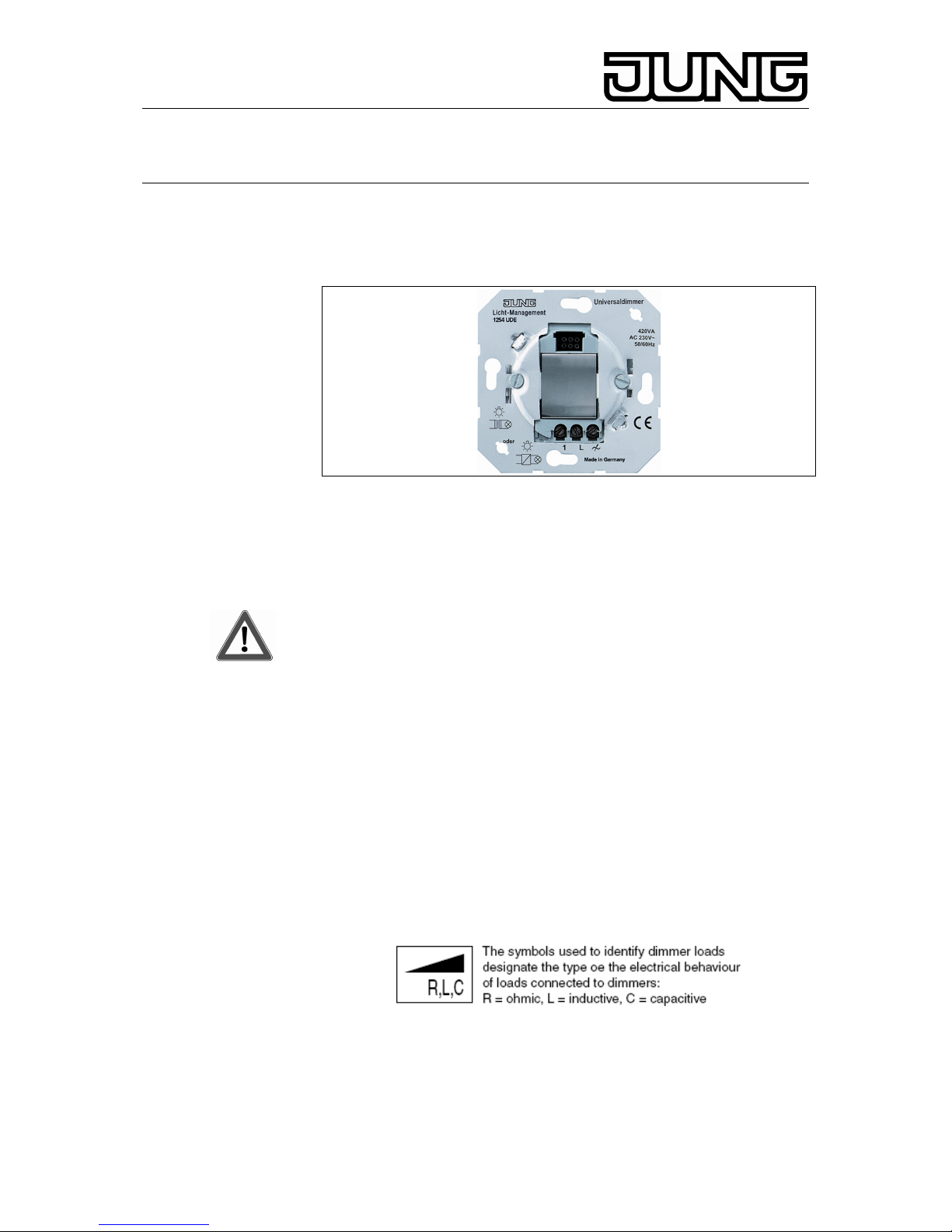
Light Management Universal dimmer
Ref.-no.: 1254 UDE
Operating Instructions
Universal dimmer
1. Warning
Attention:
Electrical equipment must be installed and fitted only by qualified
electricians and in observance of the applicable accident prevention
regulations.
Not suitable for disconnecting.
When the universal dimmer is off the load is not electrically isolated
from the mains.
When using conventional transformers, protect the primary side of
each transformer by a fuse as indicated by the manufacturer.
Do not connect any electronic lamps, e.g. switchable or dimmable
compact fluorescent lamps or LED lamps. Device can be damaged.
Only use safety transformers as per EN 61558-2-6.
Non-observance of the installation instructions may cause fire or
other hazards.
2. Function
Universal dimmer for switching and dimming extensive light sources such
as:
• 230 V incandescent lamps.
• 230 V halogen lamps.
• LV halogen lamps in conjunction with TRONIC transformers
• LV halogen lamps in conjunction with conventional transformers.
Switching and dimming commands are given when the covers of the
dimmer, of the extension insert or of the radio transmitter are actuated .
The universal dimmer works on the basis of the twoarea principle, i. e.
there is one touch area each for the ‘brighter’ and ‘darker’ dimming
directions. The lights are turned on by a lamp-saving soft start. This
Operating Instructions paper describes the functionality in combination
with the manual attachment.
Stand: Feb-10 325 274 43
Page 2
Light Management Universal dimmer
Ref.-no.: 1254 UDE
Operation from the switched-off state:
Short touch (less than 400 ms)
UPPER or LOWER touch area or full area: ON
Longer touch (more than 400 ms):
UPPER touch area: Dimming from minimum to maximum brightness.
LOWER touch area: Turning on to minimum brightness.
Operation from the switched-on state:
Short touch (less than 400 ms):
UPPER or LOWER touch area or full area: OFF
Longer touch (more than 400 ms):
UPPER touch area: Increasing the light intensity to maximum
(dimming up).
LOWER touch area: Decreasing the light intensity
to minimum (dimming down).
Full-area operation (3 s min.): The current brightness is stored and
adjusted upon restarting (short actuation).
The storing process is indicated by a soft start.
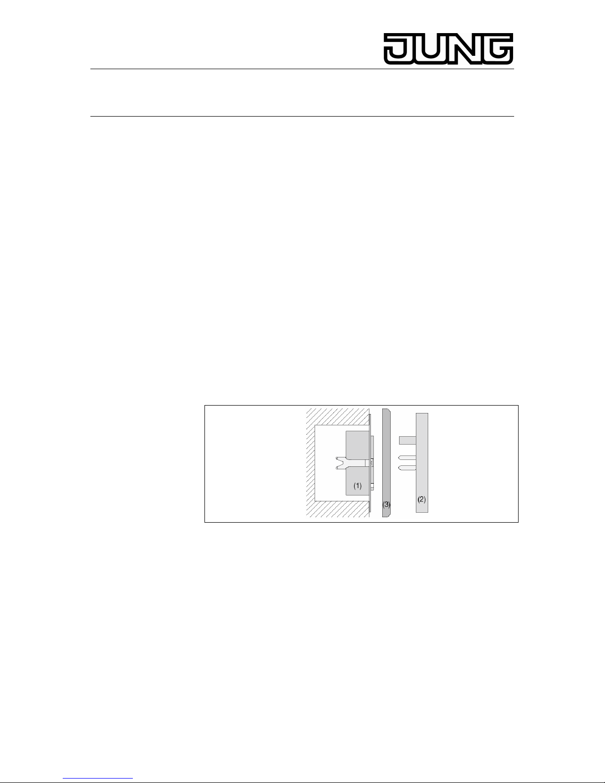
3. Installation Instructions
Fit universal dimmer insert (1) into a box as per DIN 49073 (Fig. A).
A
The connecting terminals of the insert must be at the bottom. Use the
universal dimmer insert only in combination with an attachment. Plug
attachment (2) onto the insert (1) together with frame (3). Plug on the
attachment prior to applying the mains voltage. Do not change the
attachment while the mains voltage is on, or malfunctioning will be
caused. After installation of the universal dimmer, the brightness value in
memory is the maximum brightness.
Do not connect capacitive loads (e. g. TRONIC transformers) and
inductive loads (e. g. conventional transformers) to the universal
dimmer at the same time.
2
Page 3

Light Management Universal dimmer
Ref.-no.: 1254 UDE
For resistive loads (incandescent lamps, halogen HV lamps), the learning
process becomes noticeable by short-time flickering. Depending upon the
conditions of the mains, the learning process lasts between 1 and 10 s.
During this time, no actuation is possible. In case of a short-circuit during
the learning process, the load must be learned again after the elimination
of the short-circuit. Mains failures of longer than 0.7 s. will lead to
switching off the dimmer. The overall power rating of the consumers
connected must not exceed the maximum load specified in the technical
data. Load the transformers with lamps up to at least 85 % of their rated
loads. The overall load including transformer losses must not exceed the
maximum power rating. Operation with mixed loads of the specified types
is possible up to the total admissible load.
Minimum load 50 W/VA
Depending upon the type of installation, the maximum connected load
must be reduced by:
• 10 % per 5 °C exceeding of the ambient temperature of 25°C.
• 15% for installation in wooden, gypsum plaster or hollow walls.
• 20% for installation in multiple combinations.
Short-Circuit Protection
Phase cut-off operation (capacitive load, resistive load):
Disconnection with automatic re-starting after elimination of the short-
circuit within 7 s. After this, permanent disconnection until the universal
dimmer is re-started manually.
Phase cut-on operation (inductive load):
Disconnection with automatic re-starting after elimination of the short-
circuit within 100 seconds. After this, permanent disconnection until th
universal dimmer is re-started manually.
Overtemperature Protection
Switching off in case of an excessively high ambient temperature. After
cooling down, the device must be switched back on.
4. Connection
Connect as shown in Fig. B
Fig. B
3
Page 4

Light Management Universal dimmer
Ref.-no.: 1254 UDE
For dimming from several places, refer to Fig. C
Fig. C
Power boost units can be connected to the universal dimmer to increase
the load rating when the dimmer capacity is exhausted.
Select a boost unit suited to the universal dimmer and to the load.
Further details can be found in the operating instructions of the respective
boost unit.
Connect as shown in Fig. D and E
(1) Universal dimmer insert
(2) Load
(3) extension
(4) for further extensions
(5) Power attachment EB (10 units max.)
(6) Universal power boost unit REG
Fig. D
Fig. E
4
Page 5

Light Management Universal dimmer
Ref.-no.: 1254 UDE
Note the technical connection conditions of the power stations.
Centralized telecontrol signals of the power stations may be noticed as
flickering of the lamps. This is not a defect of the dimmer.
Using Extensions
Control from an extension unit is possible only if the attachment on the
main unit is in place.
“2-wire” extension insert: The same functionality with an short lift key
as on the universal dimmer.
Mechanical button (normally open):
Short push: ON/OFF.
Longer push: Dimming to maximum brightness.
Dwell time of approx. 1 s at maximum, then dimming down to minimum
brightness. Dwell time of approx. 1 s at minimum, the dimming up to
maximum brightness. This procedure repeats continuously. Storing any
brightness value by the mechanical push-button (normally open) is not
possible. Illuminated mechanical pushbuttons must have a separate N
terminal.
5. Specifications
Rated voltage : AC 230 V ~, 50 / 60 Hz
Connected load : 50 - 420 W / VA
Type of loads: - 230 V incandescent lamps
(resistive load, phase cut-off)
- HV halogen lamps
(resistive load, phase cut-off)
- TRONIC transformers
(capacitive load, phase cut-off) or
- Conventional transformers
(inductive load, phase cut-on)
- Mixed loads of the specified types
(non-capacitive with inductive
loads).
For mixed loads with conventional transformers, do not exceed a resistive
load (incandescent lamps, halogen HV lamps) portion of 50%.
Power boost units:
EB: 10 units max.
Universal power boost unit REG: see boost unit
operating instructions.
Number of Extensions:
“2-wire” extension insert,
mechanical push-button: unlimited
extension insert for presence
detector and automatic switch: 5
Different types of extension units can be combined
Total length of extension
connecting cable: max. 100 m
Spurious radiation: according EN 55015
5
Page 6

Light Management Universal dimmer
Ref.-no.: 1254 UDE
6. Guarantee
Our products are under guarantee within the scope of the statutory
provisions.
Please return the unit postage paid to our central service
department giving a brief description of the fault:
ALBRECHT JUNG GMBH & CO. KG
Service-Center
Kupferstr. 17-19
D-44532 Lünen
Service-Line: +(49) 23 55 . 80 65 51
Telefax: +(49) 23 55 . 80 61 65
E-Mail: mail.vka@jung.de
General equipment
Service-Line: +(49) 23 55 . 80 65 55
Telefax: +(49) 23 55 . 80 62 55
E-Mail: mail.vkm@jung.de
KNX equipment
Service-Line: +(49) 23 55 . 80 65 56
Telefax: +(49) 23 55 . 80 62 55
E-Mail: mail.vkm@jung.de
The
-Sign is a free trade sign addressed exclusively to the
authorities and does not include any warranty of any properties.
6
 Loading...