

Jung TK AS AL 114, TK AS ES 114, TK AS AL 114 WW, TK AS AL 128 WW, TK AS AL 128 Product Information
...
Product Information
DCM Outdoor station
1 to 4-gang
TK AS AL 114 WW
TK AS AL 114
TK AS ES 114
2 to 8-gang
TK AS AL 128 WW
TK AS AL 128
TK AS ES 128
ALBRECHT JUNG GMBH & CO. KG
Volmestraße 1
58579 Schalksmühle
Phone +49.2355.806-0
Fax +49.2355.806-189
E-Mail: mail.info@jung.de
Internet: gb.jung.de

2
Table of content
Safety instructions................................................................................................................2
Application / Brief description...............................................................................................4
Application........................................................................................................................4
Brief description................................................................................................................4
Device overview...................................................................................................................5
Wiring and installation..........................................................................................................6
Wiring example.................................................................................................................6
Connecting diagram .........................................................................................................7
Possible connection for a door release relay....................................................................7
Installation ........................................................................................................................8
Commissioning ..................................................................................................................11
Acoustic and optical signals, pressing buttons ...............................................................11
Setting the button layout ....................................................................................................12
Bell button programming....................................................................................................14
Basic principle ................................................................................................................14
Programming a bell button .............................................................................................14
Programming a second indoor station to a bell button (parallel call) ..............................16
Deleting the programming ..............................................................................................17
Parameters ........................................................................................................................18
Settable parameters.......................................................................................................18
Setting and blocking OS address ...................................................................................18
Setting and cancelling a programming block..................................................................18
Light switching function ..................................................................................................18
Automatic light switching ................................................................................................18
Light switching................................................................................................................18
Nameplate illumination ...................................................................................................18
Setting parameters with DIP switches ............................................................................19
Labelling the nameplate.....................................................................................................21
Fault identification, indication and querying .......................................................................21
Fault sources..................................................................................................................21
Explanation of terms and definitions ..................................................................................22
General notes on the wiring in DCM audio systems ..........................................................23
Cleaning.............................................................................................................................24
Technical data ...................................................................................................................25
Acceptance of guarantee ...................................................................................................25
Safety instructions

3
!
Assembly, installation, and commissioning must only be carried out by a qualified
electrician!
For work on systems with 230 V AC mains current the safety requirements of DIN VDE
0100 must be observed.
When installing DCM BUS systems the general safety rules for telecommunication systems in accordance with VDE 0800 must be observed:
• separate cabling for high and low voltage lines
• minimum distance of 10 cm for joint cabling arrangements,
• use of separators between high and low voltage lines in joint cable ducts,
• use of standard telecommunication cables, e. g. J-Y (St) Y with 0.8 mm² cross section
• existing cables (modernisation) with different cross sections may be used whilst taking
account of the loop resistance.
!
Suitable lightning prediction must ensure that a voltage of 32 V DC will not be
exceeded at the DCM BUS wires a and b.

4
Application / Brief description
Application
• hands-free operation with high audio quality (full duplex)
• release door calls
• switching light
Brief description
• full duplex operation in combination with comfort indoor station
• half duplex operation in combination with standard indoor station
• high audio quality due to active noise suppression (noise and line echo cancellation)
• AEC (Acoustic Echo Cancellation), electronic method for acoustic echo reduction
• automatic calibration of the ambient and network conditions
• high-quality sound and great speaker dynamics
• volume adjustable
• covers for push-buttons can be combined variably, 1- to 4-gang or 2- to 8-gang
• acknowledge tone for bell button
• acoustic status indication if system is occupied (existing communication)
• automatic call cut-off
• durable energy saving LEDs for labelling illumination
• fault analysis due to different flashing of the LED labelling illumination
• fault differentiation due to acoustic feedback signal when pressing a bell button
• weather-proof loudspeaker
• solid, robust metal faceplate
• stainless steel flush mounted housing
• adjustable installation frame
• integrated dismounting protection
• bell button configured for switching light (basic settings)
• bell button switches light depending on brightness (automatic light)
• brightness threshold adjustable
• programming possible without access to flats
• connection: 3-wire-technique
• electret capacitor microphone
• audio and video stations can be combined in the same installation
• inscription fields can be labelled with the JUNG labelling tool
(www.jung-label.de)
5
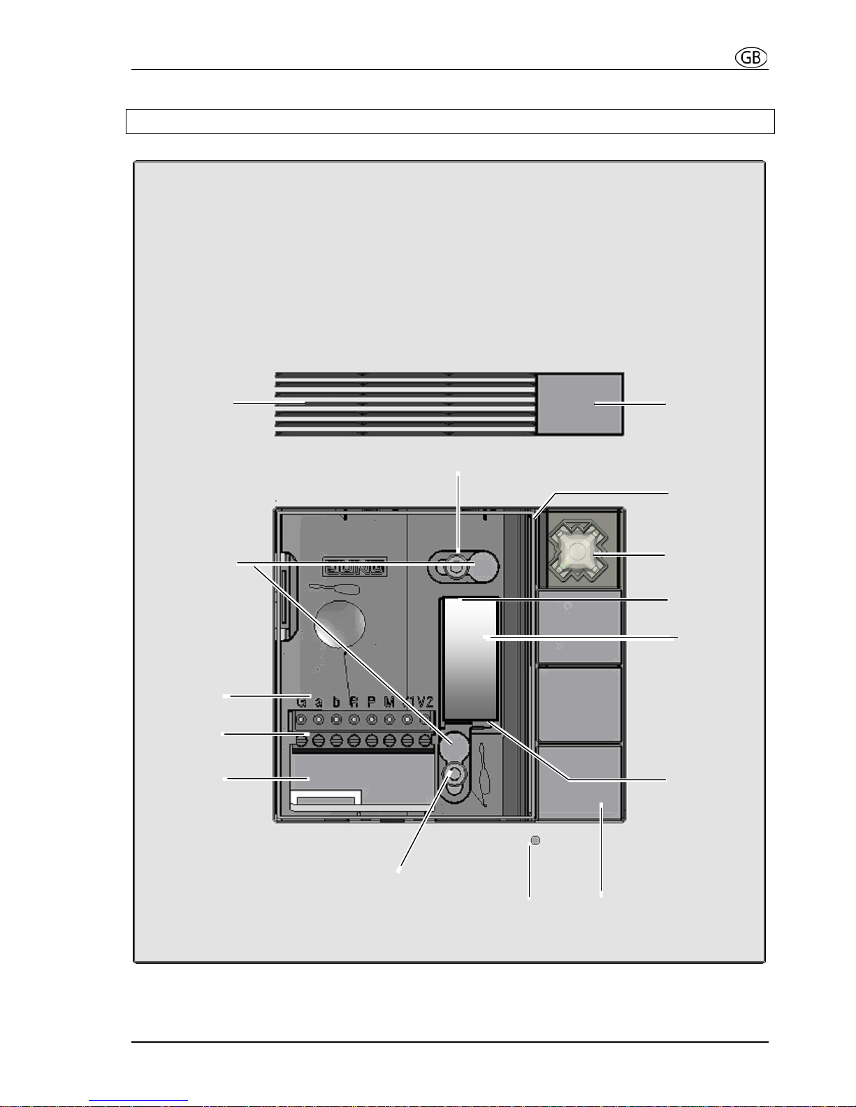
Device overview
Fig: TK AS AL 114, without inscription plate
Screw
Screw
Terminals
Pluggable
EEPROMboard
DIP
switch
Loudspeaker
Mounting hole
Bell button
Cable entry
Microphone hole
Light sensor
Terminal
description
Faceplate
Inscription
plate
illumination
Cover
Plug-in
position for
bell button
6
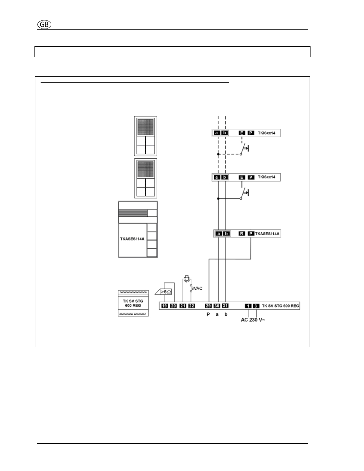
Wiring and installation
Wiring example
2-wire technique
Please observe cable length and loop resistance.
Indoor station
Indoor station
Outdoor station
Power supply &
control unit
Floor bell button
Floor bell button
Door release
relay and
illumination
7
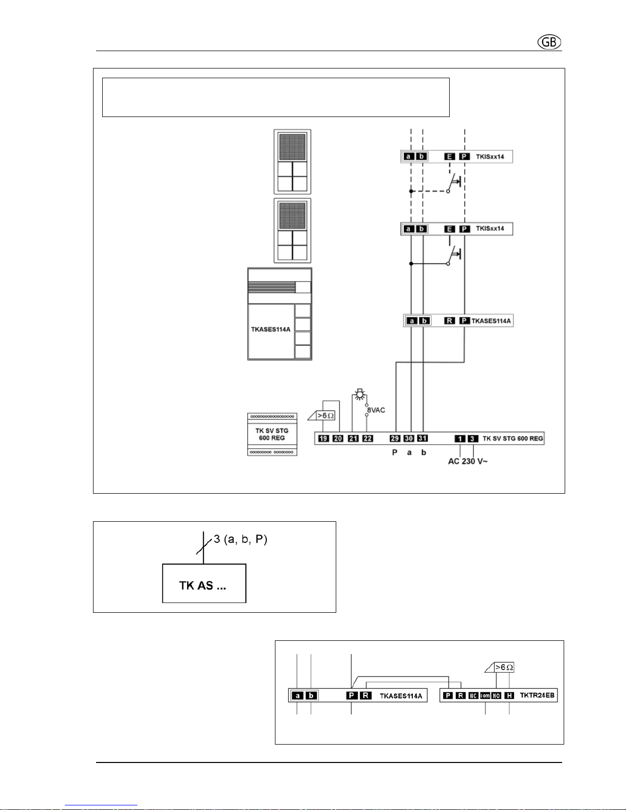
Connecting diagram
Possible connection for a door release relay
Please use
door release relay TK TR 24 EB.
Floating relay contact:
Max. AC 24 V, 2 A of external
power supply
3-wire technique
Please observe cable length and loop resistance.
~
Indoor station
Indoor station
Outdoor station
Power supply &
control unit
Floor bell button
Floor bell button
Door release
relay and
illumination
8
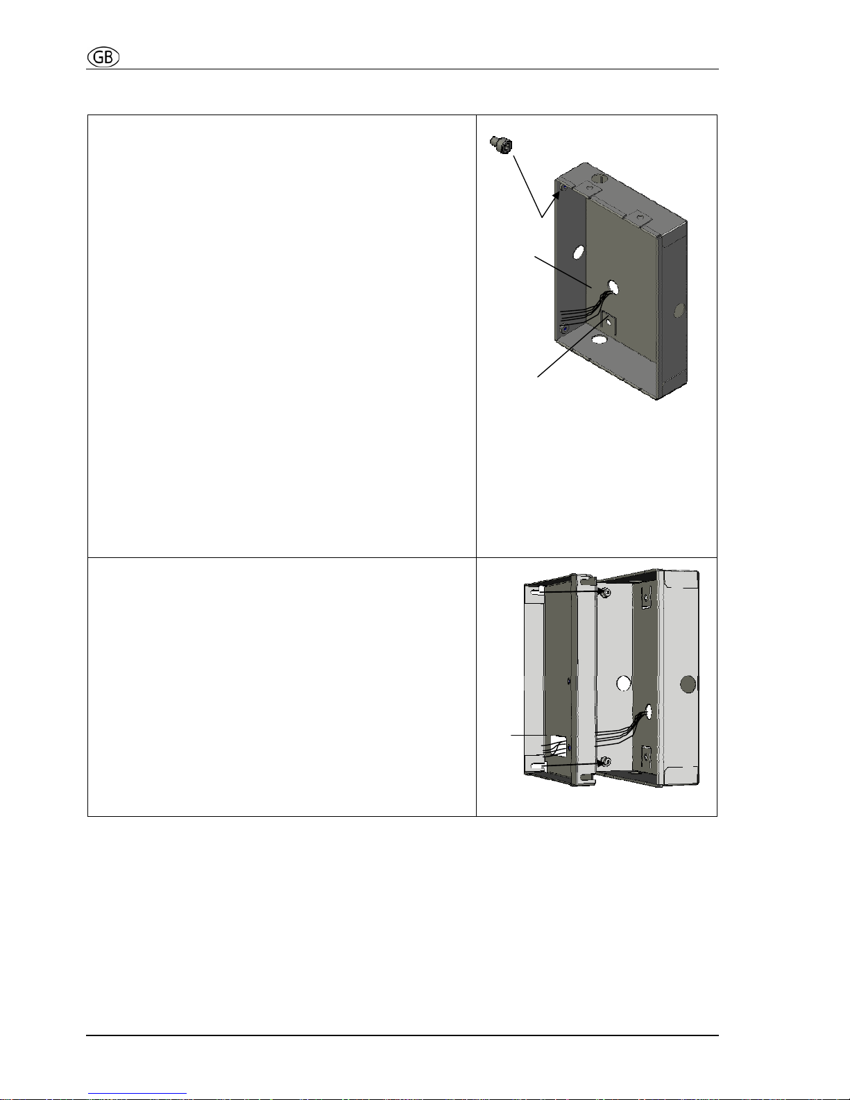
Installation
Flush mounted housing
• Fasten the 4 delivered short hexagon screws (1)
with a hexagon key.
• Shut the unused cable entry holes with the
delivered dummy plug.
• Put the wires through the selected cable
entry hole (2).
• Connect the flush mounted housing into the wall.
The edge of the housing has to be flush with the
wall surface to enable, that the faceplate of the
outdoor station fits flat on the wall.
Connection possibilities:
• Connect the strap (3) of the housing with screws to
the wall.
• Attach with plaster by means of using plaster
straps (4 metal sheets with holes, 4 screws and 4
nuts). These plaster straps can be connected on
the reverse side of the housing to the housing
straps (3).
Flush mounted housing
Installation frame
The wall is plastered and the housing is installed flush
with the plaster into the wall.
• Unscrew the 4 hexagon screws until they stick out
half length.
• Put the wires through the cable entry hole of the
installation frame (5).
• Put the installation frame into the housing in that
way, that the slots of the frame fit behind the screw
heads.
• Press the installation frame into the flush mounted
housing and tighten the hexagon screws.
Installation frame
1
2
3
5
 Loading...