

Page 1
ALBRECHT JUNG GMBH & CO. KG
Volmestraße 1
D-58579 Schalksmühle
www.jung.de
325 569 03 12.05
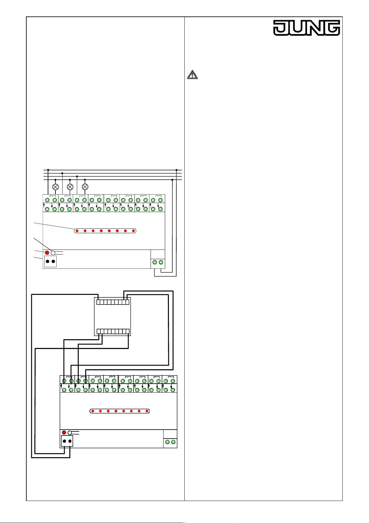
fig. A
L1
L2
L3
N
A1
A2
A3 A4
A2' A3' A4'
A1'
(1)
(2)
(3)
(4)
- +
24 V DC
80 mA
E2 E3 E4
E1
A1 A2 A3 A4 A5 A6 A7 A8
A5
A5'
E5
A6
A6' A7' A8'
E6
A8
A7
E7
E8
LN
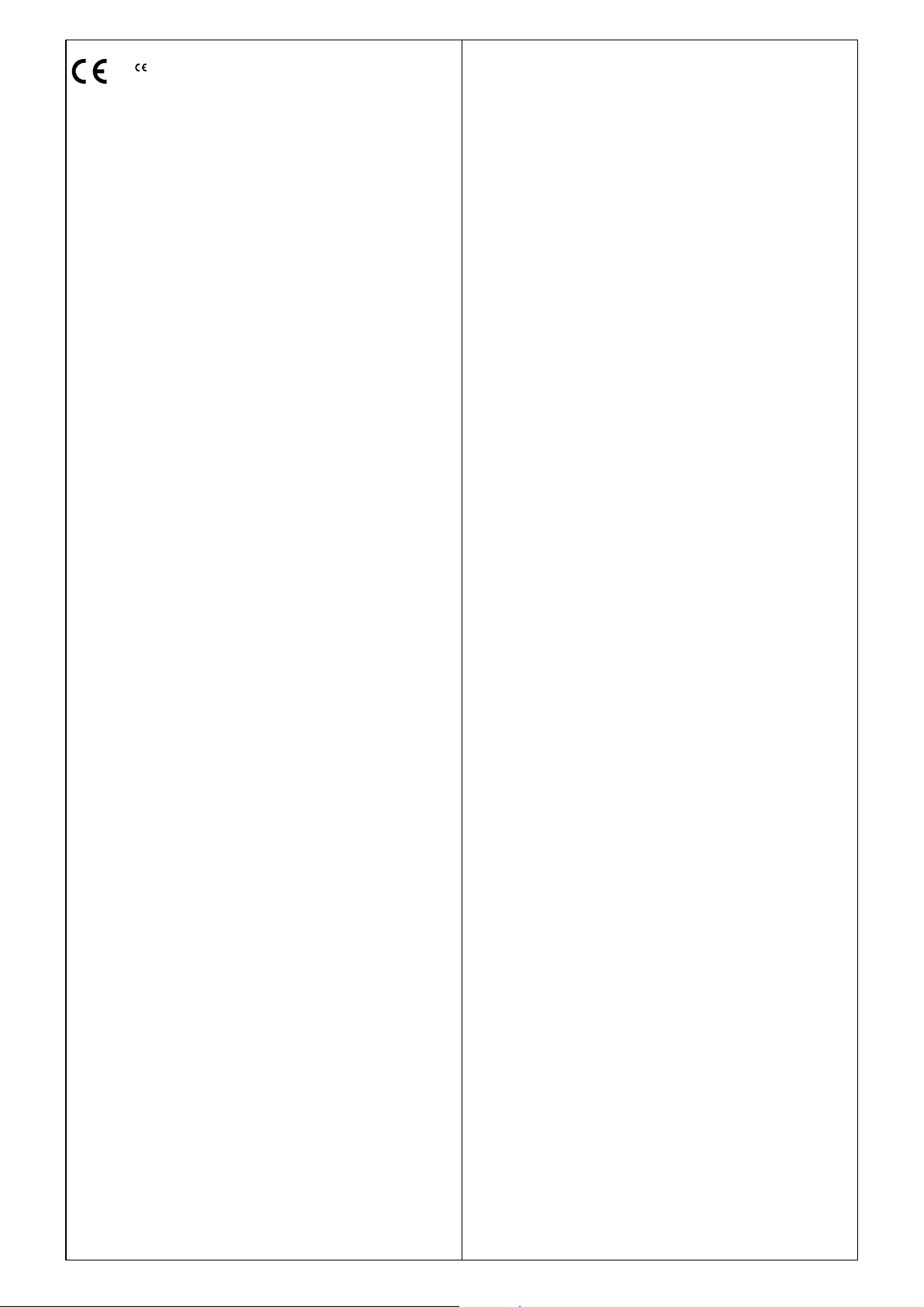
fig. B
43215678+
Output ter minals
Touch Sensor
..2248..
LED inputs
321 5678-
4
A2 A3 A4 A5 A6 A7 A8
A1' E1
- +
24 V DC
80 mA
A2'
E2 E3
A3' A4' E5
A1 A2 A3 A4 A5 A6 A7 A8
E4
A6'
E6
A7'
E7
A8'
LN
AC 230 V ~
8-channel relay station
Operating instructions
Art. Nr. RS8REG
Safety warnings
Attention: Electrical equipment must be installed and fitted only
by qualified electricians.
To prevent electric shocks, disconnect the mains supply (by
cutting out the circuit breaker) before working on the device.
or on the load. Failure to observe any of the installation
instructions may result in fire and in other hazards.
Function
Important:
The relay station is not a KNX / EIB device.
The relay station is equipped with 8 potential-free load contacts (n.o.
contacts) for a maximum current of 10 A each for the switching of
different loads, e.g. lighting.
The relay station can be operated as a momentary-contact (toggle
mode) or as a maintained-contact (doorbell mode) actuator.
The station is controlled with an AC/DC 24V 20 mA touch sensor (e.g.
Art. no. ..2248..) or with mechanical pushbuttons.
The output terminals A1‘ – A8‘ can be used for the connection of
checkback LEDs.
The relay station supplies the control voltage (positive pole) for the
switching inputs (E1-E8) and the common ground line for the
checkback LEDs at its DC output
Operation
The relay station is operated by means of the connected touch
sensor.
The red LEDs (1) of the relay station indicate the switching state of
the relay contacts.
relay contact closed LED on
relay contact closed open LED off
Fitting
Fit the relay station by snapping it onto a mounting rail as per DIN EN
50022.
Installation:
Connect the supply voltage AC 230 V ~ for the relay station to
terminals "L" and "N", see fig. A.
Connect the loads to be switched to the output terminals A1 – A8 of
the relay station, see fig. A. The illustration shows 3 lamps connected
to different phase conductors. The remaining terminals are connected
in the same way.
The schematic in fig. B shows the relay station used in combination
with the AC/DC 24V 20 mA touch sensor.
Mechanical pushbuttons, e.g. 534U, can be used as an alternative.
Connect the switching inputs of the relay station E1 – E8 with outputs
1 - 8 of the touch sensor (e.g. Art. no. ..2248..).
The schematic in fig. B is a wiring example. The remaining terminals
E8A5'
are connected in the same way.
Connect the LED inputs 1 - 8 of the touch sensor with the output
terminals A1‘ – A8‘ (DC 24 V, 10 mA) of the relay station.
The schematic in fig. B is a wiring example. The remaining terminals
are connected in the same way.
In this case, the switching state of the relay contacts is indicated by
the LEDs of the touch sensor
relay contact closed LED on
relay contact closed open LED off
Connect the 24 V DC output (4) of the relay station with the correct
polarity to the touch sensor, see fig. B.
Important:
In the event of a short-circuit at the DC output,
the station will no longer accept commands from the
pushbutton.
the relays will switch off briefly (ca. 1 s).
Page 2
The -sign is a free trade sign addressed
exclusively to the author iti es an d does not
include any warranty of any properties.
Commissioning
Pushbutton (2) and LED (3) are accessible only during the fitting and
installation activities, see fig. A.
For switching over between the two modes of operation press the
pushbutton (2) for at least 7 s.
The selected opmode is stored in a non-volatile memory.
The device is delivered preset to the toggle mode.
doorbell mode LED (3) lit up red;
the relay contact is closed as long as the
control pushbutton is kept depressed.
toggle mode LED (3) lit up green
the relay contact is closed or opened after
each press of the control pushbutton.
Response to mains failures
After a mains failure, all relay contacts are open and must be
activated again.
Troubleshooting
If an undefined fault occurs during operation of the device, the
LED (3) lights up yellow.
Acknowledge the fault by pressing the pushbutton (2) for ca. 1.5 s.
The relay station is then in the toggle mode. If necessary, switch over
to the other opmode, see commissioning.
Technical Data
Rated voltage: AC 230 / 240 V ~, 50 / 60 Hz
Operating temperature: - 5 °C ... + 45 °C
Storage temperature: - 25 °C ... + 70 °C
Fitting width: 144 mm (8 modules)
Outputs A1 – A8
Contact type: potential-free n.o. contact (µ contact)
Switching capacity: AC 250 V ~ / 10 A
Contact rating:
incandescent lamps: 1400 W
HV halogen lamps: 1225 W
conventional transformers: 1200 VA
Tronic transformers: 1200 VA
motors: 600 W
fluorescent lamps: not approved
minimum load: 12 V, 100 mA
Outputs A1‘ – A8‘: R
DC 24 V / 10 mA max.
= 330 Ω
out
Switching inputs E1 – E8: Rin = 200 kΩ
24 V max.
Screw terminals
0.5 – 4 mm² single wire
2 x 0.5 – 2.5 mm² single wire
0.34 – 4 mm² stranded without ferrule
0.14 – 2.5 mm² stranded with ferrule
DC output: 24 V DC, 80 mA
pushlock terminals
Power consumption
Typically (all relays on): 7.7 W
Maximum (all outputs at full load) 12.5 W
Standby: 0.5 W
Length of control line: 100 m max.
Technical specifications subject to change
Please leave these instructions with your customer after installation.
Guarantee
Our products are under guarantee within the scope of the statutory
provisions.
Please return the unit postage paid to our central service
department giving a brief description of the fault:
ALBRECHT JUNG GMBH & CO. KG
Service-Center
Kupferstr. 17-19
D-44532 Lünen
Service-Line: +49 (0) 23 55 . 80 65 53
Telefax: +49 (0) 23 55 . 80 61 65
E-Mail: mail.vka@jung.de
Technical matters (general)
Service-Line: +49 (0) 23 55 . 80 65 55
Telefax: +49 (0) 23 55 . 80 62 55
E-Mail: mail.vkm@jung.de
Technical matters (KNX / EIB)
Service-Line: +49 (0) 23 55 . 80 65 56
Telefax: +49 (0) 23 55 . 80 62 55
E-Mail: mail.vkm@jung.de
 Loading...