

Page 1

Operating instruction
Radio
Ref. no.: RAN ..514..
RAN ..914..
Page 2

Page 3

Table of contents
1. Safety notes................................................................................................... 3
2. Device overview............................................................................................ 4
2.1.Operating elements........................................................................................ 4
3. Function......................................................................................................... 5
3.1.Intended use .................................................................................................. 5
3.2.Product features............................................................................................. 5
4. Operation....................................................................................................... 6
5. Information for specialist electricians........................................................ 7
5.1.Installation and electrical connection ............................................................. 7
6. Commissioning............................................................................................. 9
7. Technical data............................................................................................... 9
8. Guarantee .................................................................................................... 10
1. Safety notes
The installation and assembly of electrical devices may only be carried out
by specialist electricians.
If these instructions are not followed, the device may be damaged and fire
or other dangers may arise.
Before working on the device or disconnecting the load, take into account
all the line circuit-breakers which supply hazardous voltage to the device or
load.
These operating instructions are part of the product and must remain with
the end customer.
3
Page 4
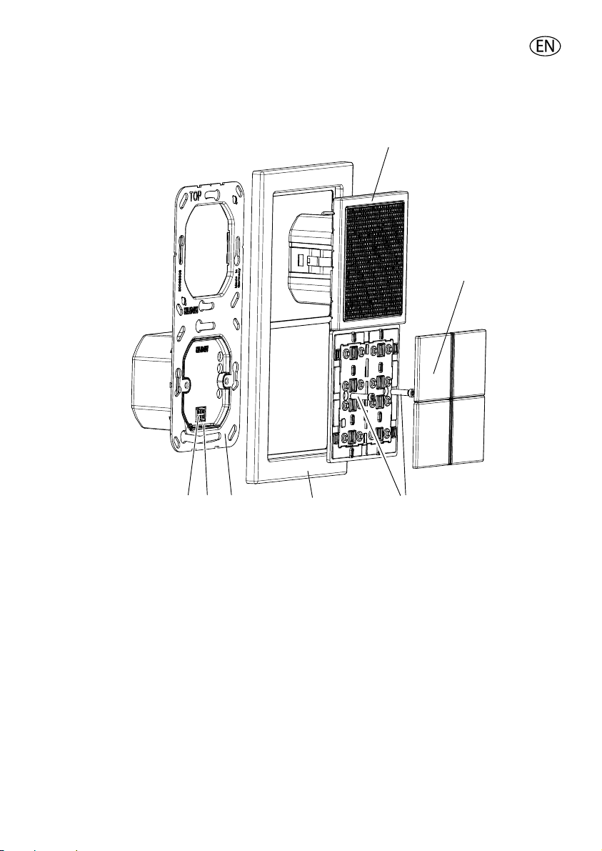
2. Device overview
1
2
7
fig. 1: Exploded diagram
(1) Radio
(2) Button set
(3) Plastic screws
(4) Frame
(5) Retaining ring with PSU
(6) Lever
(7) Output for PSU
L The frame is integrated for the design ranges AS 500,A 500 and CD 500
56
4
3
2.1. Operating elements
The radio functions are controlled via the buttons.
4
Page 5

Switching the radio on
Short actuation switches the radio on/off
Long actuation when the radio is switched on changes it to sleep mode
Volume
Volume control loud / quiet
Memory
Storing of the four preferred stations
- - -
3. Function
3.1. Intended use
• Installation in two flush-type boxes in accordance with DIN EN 49073
(recommendation: deep boxes)
• Preferred installation: vertical
Order a separate button set for horizontal installation
• FM reception in the frequency range 87.5 MHz to 108 MHz
3.2. Product features
• Simple operation with additional status response LED
blue LED lights up: operating display
blue LED flashes: sleep mode active
red LED: preferred station
• High-quality tone and great loudspeaker dynamics
• Optimised acoustics through the use of a bass reflex enclosure
• Integrated FM antenna
• High reception quality
• Automatic and manual station scan
• Non-volatile storage of 4 preferred stations
(the stored stations are retained after voltage failure)
• Switch on with the last station and saved volume
• Sleep mode (switch off after approx. 30 minutes)
• Switching on/off possible via extension unit e.g. light
• Switching on/off possible via floating contact A/B e.g. time switch with
floating contact
5
Page 6

4. Operation
Switching the radio on/off
Press button briefly
Device switches on/off
The blue LED lights up/switches off
L The last selected station is retrieved at the last set volume.
Sleep mode
The radio is switched on.
Press and hold button (approx. 3 seconds).
The blue LED flashes.
The radio is switched off after approx. 30 minutes.
Automatic station scan
Press and hold button (approx. 3 seconds)
The long actuation is acknowledged by a tone.
The entire frequency range is scanned and the four stations with the strongest
signal are stored (automatic assignment of memory space).
L Memory is overwritten.
Manual station scan
Search for the station in descending/ascending frequency.
Press button briefly
The next station is selected.
Save/overwrite preferred stations
The required transmission frequency is selected.
Press and hold down the required memory button
(approx. 3 seconds).
The save is acknowledged by a tone.
The transmission frequency is stored.
- - or
L If the memory location is already occupied, it is overwritten with the new
transmission frequency.
6
Page 7

Select preferred stations
Press the memory button
The associated red LED lights up
The stored station is received
Volume
The button regulates the volume
Press the + button
louder
Press the - button
quieter
- - or briefly
5. Information for specialist electricians
L DANGER!
Risk of an electric shock when touching live parts. Electric shock can
lead to death.
Before working on the device, isolate the connecting cables and cover
any active components in the surrounding area.
5.1. Installation and electrical connection
Connecting and installing the radio
Installation in two flush-type boxes in accordance with DIN EN 49073.
For LS Design ranges the installation into 2-gang and 3-gang surface caps is
possible.
The installation is either vertical or horizontal.
L For A, CD and FD ranges, lever (6) is in position A, while lever is in position B
for LS ranges.
Connection of the PSU according to wiring diagram (fig 2). Connection of the
extension unit is optional. Connection A and B on the radio (fig 3) for connection
to a floating contact (e.g. time switch with floating contact).
Plug radio with frame onto PSU. Observe contacts of PSU. Connect radio to the
supporting frame with enclosed plastic screws. Do not overtight the plastic
screws. Clip on covers.
L The antenna is integrated.
7
Page 8

A
6
fig. 2: Connection power supply
B
L,N Connection AC 230 V~
1 Connection of extension unit
A/B Floating contact
L CAUTION!
Do not connect any voltage to the floating contact A/B.
AB
fig. 3: Connection A and B for floating contact
8
Page 9

6. Commissioning
After the initial commissioning, an automatic station scan is carried out.
The entire frequency range is scanned and stores the four stations with the
strongest signal at memory locations 1 to 4.
Appendix
7. Technical data
Nominal voltage: AC 230 V ~
Frequency: 50/60 Hz
Ambient temperature: approx. 0…+ 50 °C
Humidity: approx. 15 % … 90 % no moisture condensation
Frequency range: 87.50 MHz … 108.00 MHz
Type of protection: IP 20
Connection: Screw terminals
2.5 mm² or 2 x 1.5 mm²
9
Page 10

8. Guarantee
Guarantee is provided within the framework of legal requirements.
Please send the device postage paid with a description of the error to our
central Customer Service department:
ALBRECHT JUNG GMBH & CO. KG
Service Center
Kupferstr. 17-19
D-44532 Lünen
Service line: +49 23 55 . 80 65 51
Fax: +49 23 55 . 80 61 89
Email: mail.vki@jung.de
Technical (general)
Service line: +49 23 55 . 80 65 55
Fax: +49 23 55 . 80 62 55
Email: mail.vkm@jung.de
The CE mark is a free trade sign addressed exclusively to the authorities
and does not include any warranty of any properties.
Technical (KNX)
Service line: +49 23 55 . 80 65 56
Fax: +49 23 55 . 80 62 55
Email: mail.vkm@jung.de
10
Page 11

Page 12

Albrecht Jung GmbH & Co. KG
Volmestraße 1
D-58579 Schalksmühle
Service line: +49.23 55.8 06-0
Fax +49.23 55.8 06-1 89
Email: mail.vki@jung.de
Internet: www.junguk.com
www.jung-catalogue.com/
0024013702 06.08
 Loading...