

Jung MK-POF-UAE-REG, MK-POF-2UAE Quick Start Manual
GB
D
Media converter 1-gang
Safety Instructions
Electrical equipment may only be installed and
tted by electrically skilled persons.
Serious injuries, re or property damage possib-
le. Please read and follow manual fully.
In order to full the general safety regulations
of telecommunication systems and to avoid
interference, the DIN VDE0100 Part 520 and the
prEN 50174-2:1998, sections 5.4 and 5.5 have to
be followed. A physical separation or suitable
separating pieces shall be provided (distance or
shielding).
These instructions are an integral part of the product, and must remain with the endcustomer.
Fitting and electrical connection
DANGER!
Electrical shock when live parts are touched.
Electrical shocks can be fatal.
Before working on the device, disconnect the power supply and cover up liveparts in the working
environment.
Fitting the device
• Mount device on DIN rail. (Fig. 1)
Cutting and connecting the POF-cable
After having laid the POF-cable shorten it as described below:
1. Cautiously split the cable down the middle for
approx. 30 mm and make sure that there is no
unevenness on the coating which could hinder
the inserting of the cable.
2. Insert the cable into the POF cutting tool and cut
it by pressing the blade.
3. Make sure that both wires are equally long.
4. Open the POF terminal by slightly pulling it out
and remove the red protection cap (Fig. 2).
5. Insert the POF-cable. Make sure that it is pushed
all the way up to the stop in order to guarantee a
safe connection.
6. Close the POF terminal by pushing it into the
opening of the device thus fastening the cable.
Connecting of the power supply.
1. To install the power supply to the Media converter
2. Remove dust cover and connect your Ethernet
devices (PC, router,set top box e. g.) up to the
RJ45 terminal jack via the enclosed patchcables.
3. Mark labelling strip and place under the cover
Medienkoppler REG 1fach
Sicherheitshinweise
Einbau und Montage elektrischer Geräte dürfen
nur durch Elektrofachkräfte erfolgen.
Schwere Verletzungen, Brand oder Sachschäden möglich. Anleitung vollständig lesen und
beachten.
Um die allgemeinen Sicherheitsbestimmungen
für Fernmeldeanlagen zu erfüllen und um Stör-
beeinussungen zu vermeiden, muss die DIN
VDE 0100 Teil520 bzw. die prEN 50174-2:1998,
Abschnitte 5.4 und 5.5 beachtet werden: Eine
physische Trennung oder geeignete Trennstege
sind vorzusehen (Abstand oder Schirmung).
Diese Anleitung ist Bestandteil des Produktes
und muss beim Endkunden verbleiben.
Montage und elektrischer Anschluss
GEFAHR!
Elektrischer Schlag bei Berühren spannungsfüh-
render Teile.
Elektrischer Schlag kann zum Tod führen.
Vor Arbeiten am Gerät freischalten und spannungsführende Teile in der Umgebung abdecken!
Gerät montieren
• Gerät auf Hutschiene montieren (Bild 1).
Zuschneiden und Anschließen des POF-Kabels
Nach dem Verlegen des POF-Kabels gehen Sie
folgendermaßen vor:
1. Trennen Sie das Kabel in der Mitte ca. 30 mm
vorsichtig auf und achten Sie darauf, dass keine
Unebenheiten des Mantels das Einführen des
Kabels behindern können.
2. Führen Sie es in das POF-Schneidewerkzeug ein
und schneiden Sie es durch Druck auf die Klinge
ab.
3. Achten Sie darauf, dass beide Adern gleich lang
sind.
4. Öffnen Sie die POF-Klemme durch leichtes Ziehen am schwarzen Anschluss und entfernen Sie
die rote Schutzkappe (Bild 2).
5. Führen Sie das POF-Kabel ein und achten Sie
darauf, dass es bis zum Anschlag geschoben
wird, um eine sichere Verbindung zu gewährleisten.
6. Schließen Sie die POF-Klemme, indem Sie den
schwarzen Anschluss zum Fixieren des Kabels in
die Geräteöffnung schieben.
Anschließen der Netzspannung
1. Schließen Sie die Spannungsversorgung an den
Medienkoppler
2. Öffnen Sie die Staubschutzklappe und schließen
Sie Ihre Ethernet-Geräte (z. B. PC, Router, SetTop-Box) über Patchkabel am RJ45-Anschluss
an.
3. Beschriften Sie den Einleger und setzen ihn unter
der Abdeckung ein.
Medienkoppler REG 1fach
Art.-Nr.: MK-POF-UAE-REG
Kurzbedienungsanleitung/Quick Guide
293740 Stand 04.07.2014
J:0024074000
ALBRECHT JUNG GMBH & CO. KG
Volmestraße 1
58579 Schalksmühle
Telefon: +49.23 55.8 06-0
Telefax: +49.23 55.8 06-2 04
kundencenter@jung.de
www.jung.de
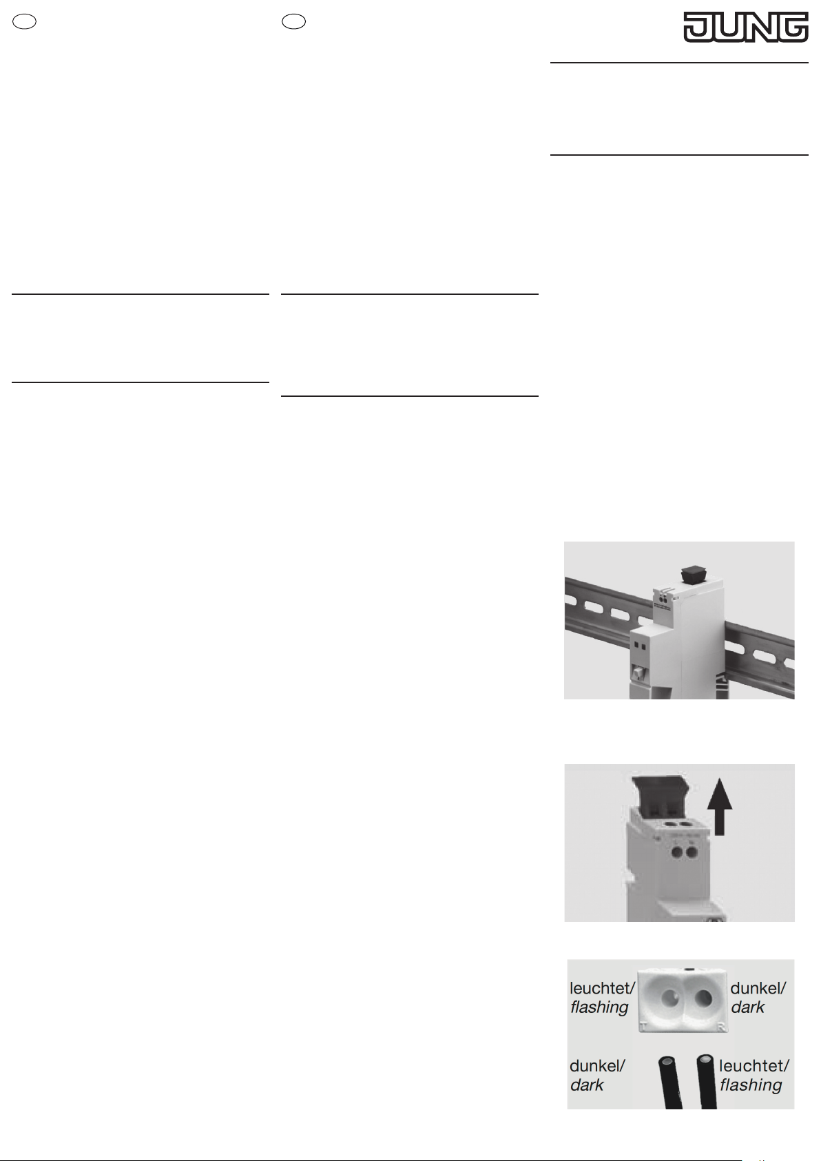
Bild 1
When connecting the POF-cable make sure to insert
the bright wire into the dark (not bright) terminal and
the dark (not bright) wire into the bright terminal
(Fig. 3).
Technical Data
Power supply: 8-24 V DC
8-12 V AC
Power consumption: 0,9 W
Operation temperature: -5 to +45 °C
Transmission rate: 100 Mbit/s
Transmission length: 70 m with POF 2.2 mm
Electrical data connection: RJ45
Optical data connection: 2.2 mm Duplex POF
Wave length: 660 nm typical
Accessories
Power supply NT1220 REG VDC
Achten Sie beim Anschluss des POF-Kabels darauf,
dass die leuchtende Ader in die nicht leuchtende
(dunkle) Klemme und die nicht leuchtende Ader in
die leuchtende Klemme gesteckt wird (Bild 3).
Technische Daten
Nennspannung: 8-24 V DC
8-12 V AC
Leistungsaufnahme: 0,9 W
Betriebstemperatur: -5 bis +45 °C
Übertragungsgeschwindigkeit: 100 Mbit/s
Übertragungslänge: 70 m mit POF 2,2 mm
Elektrischer Datenanschluss: RJ45
Optischer Datenanschluss: 2,2 mm Duplex POF
Wellenlänge: 660 nm typisch
Zubehör
Spannungsversorgung 24 V NT1220 REG VDC
Bild 2
Bild 3

GB
D
Warranty
We reserve the right to make technical and formal
changes to the product in the interest of technical
progress.
We provide a warranty as provided for by law.
Please send the device with a description of the
defect to our central customer service ofce.
ALBRECHT JUNG GMBH & CO. KG
Service Center
Kupferstr. 17-19
44532 Lünen
Germany
Gewährleistung
Technische und formale Änderungen am Produkt,
soweit sie dem technischen Fortschritt dienen,
behalten wir uns vor.
Wir leisten Gewähr im Rahmen der gesetzlichen
Bestimmungen.
Bitte schicken Sie das Gerät mit einer Fehlerbeschreibung an unser Service Center.
ALBRECHT JUNG GMBH & CO. KG
Service Center
Kupferstr. 17-19
44532 Lünen
Germany
 Loading...