

Page 1
KNX Sensoren
Art.-no.: WS 10 D, WS 10 T, WS 10 H
Operating Instructions
Brightness Sensor, Temperature Sensor
Twilight sensor
1. Function ............................................................................................. 1
2. Safety instructions............................................................................ 1
3. Connection......................................................................................... 1
4. Fitting instructions............................................................................2
5. Technical Data................................................................................... 2
6. Acceptance of guarantee.................................................................. 3
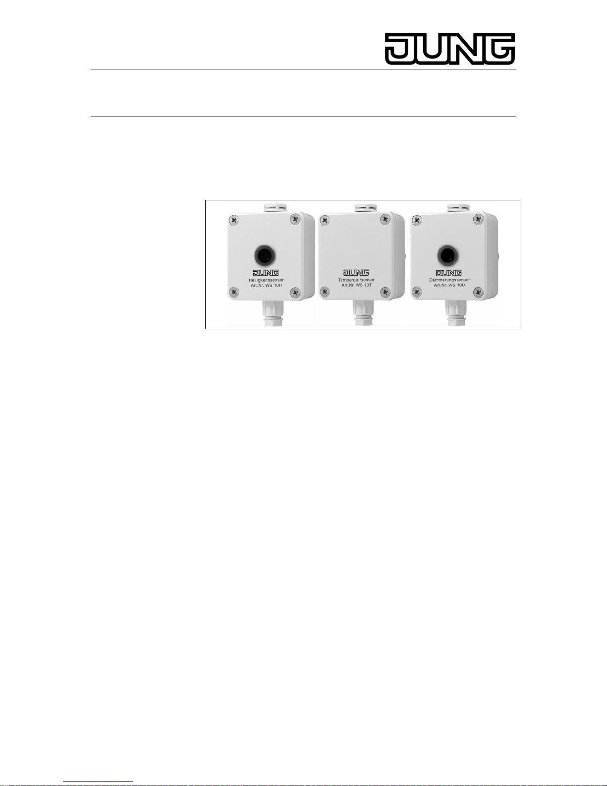
1. Function
The climatic data of interest are collected by three different transducers,
ie. the brightness sensor, the twilight sensor (Fig. ) and the temperature
sensor (Fig. ) and converted into analogue voltage signals (0 – 10 V).
The evaluation of these signals requires additional electronics (e.g.
instabus weather station) which offers the capability of transmitting
measured value or instruction telegrams to the EIB instabus depending
on the analogue signals received. To prevent the formation of moisture
inside the housings, the sensors are equipped with pressurecompensating elements (weatherproofing membrane).
2. Safety instructions
Attention: Electrical equipment must be installed and fitted by
qualified electricians only.
Subject to change without notice.
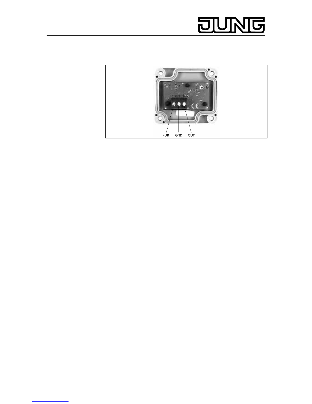
3. Connection
The connecting cables passes through the screwed conduit entry no. 7 to
the connecting terminals.
Stand: Okt-07 825 060 03
Page 2
KNX Sensoren
Art.-no.: WS 10 D, WS 10 T, WS 10 H
Terminal designations:
+UB: operating voltage 24 V DC
GND: reference potential (ground) non-earthed
OUT: output 0 – 10 V
4. Fitting instructions
• The sensors must be installed in an accessible place to permit
necessary cleaning, if needed.
• Do not install the sensors in the vicinity of RF transmitters (e.g.
cellular radio transmitters).
• Do not lay sensor cables parallel to mains or other electrically loaded
lines. To prevent EMC problems, there should be a distance of a few
centimeters between these lines and the sensor cable.
• Make sure the sensors are perfectly adjusted (e.g. pointing in the
right direction) as the measured values might otherwise be incorrect.
5. Technical Data
General
Supply voltage : 24 V DC (15 - 30 V DC)
Connecting terminals : screw-type terminals,, max. 2,5 mm²
Connecting cable: through screwed conduit entry no. 7
Recommended cable: 3 x 0,25 mm²
Length of cable: max. 100 m
(observe installation ínstructions)
Voltage output : 0...10 V DC
(into a load of at least 1 kΩ, shortcircuit
protected)
Ambient temperature : - 30 to + 70 °C
Type of protection: IP 65
Mounting position : optional
recommend:
Type of fastening: screw fastening
Dimensions : 58 x 90 x 35 mm
2
Page 3

KNX Sensoren
Art.-no.: WS 10 D, WS 10 T, WS 10 H
Weight: ca. 200 g
Twilight sensor
Measuring range: 0 bis 255 Lx, linear
Operating current: ca. 5 mA
Brightness sensor
Measuring range 0 bis 60 klx, linear
Operating current: ca. 5 mA
Temperature sensor
Measuring range: - 30 bis + 70 °C, linear
Operating current ca. 3 mA
Subject to change without notice..
6. Acceptance of guarantee
We accept the guarantee in accordance with the corresponding legal
provisions.
Please return the unit postage paid to our central service
department giving a brief description of the fault:
ALBRECHT JUNG GMBH & CO. KG
Service-Center
Kupferstr. 17-19
D-44532 Lünen
Service-Line: 0 23 55 . 80 65 51
Telefax: 0 23 55 . 80 61 89
E-Mail: mail.vki@jung.de
General equipment)
Service-Line: 0 23 55 . 80 65 55
Telefax: 0 23 55 . 80 62 55
E-Mail: mail.vkm@jung.de
Technik (KNX)
Service-Line: 0 23 55 . 80 65 56
Telefax: 0 23 55 . 80 62 55
E-Mail:
mail.vkm@jung.de
3
 Loading...