

Page 1
Signal panel
Signal panel
Art.-No.: MBT 2424
Operating instructions
1 Safety instructions
Electrical equipment may only be installed and fitted by electrically skilled persons.
Failure to observe the instructions may cause damage to the device and result in fire and
other hazards.
Do not use any sharp objects, acids or organic solvents for cleaning. Device can be
damaged.
Do not operate the device with sharp or pointed objects. The surface could be damaged.
These instructions are an integral part of the product, and must remain with the end
customer.
2 Device components
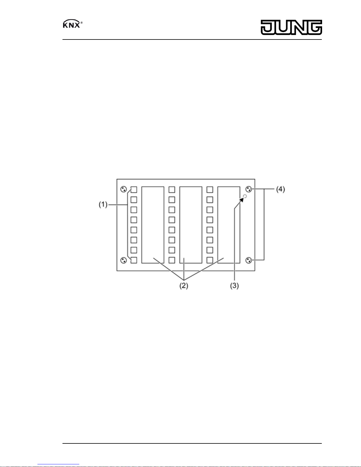
Figure 1: Front view
(1) Sensor areas with status LED
(2) Labelling with push-in labels
(3) Position of the programming LED
(4) Fastening screws, front plate
A suitable bit for the safety screw is included.
3 Function
System information
This device is a product of the KNX system and complies with the KNX directives. Detailed
technical knowledge obtained in KNX training courses is a prerequisite to proper
understanding.
The function of this device depends upon the software. Detailed information on loadable
software and attainable functionality as well as the software itself can be obtained from the
manufacturer´s product database. Planning, installation and commissioning of the device are
carried out with the aid of KNX-certified software. The latest versions of product database and
the technical descriptions are available on our website.
1/7
82575503
J:0082575503
07.12.2010
Page 2
Intended use
- Operating loads, e.g. light switching and dimming, controlling blinds/shutters, etc.
- Visualising switching states
- Concealed mounting in double appliance box - without centre bar - to DIN 49073
Product characteristics
- Push-button functions: switching, scanning, dimming, Venetian blind, value transmitter,
calling up modes, etc.
- High-quality glass surface with 24 buttons
- Operation through touching the sensor buttons
- Labelling with push-in labels
- Status indication with 24 LEDs; the colours red, green and blue can be configured
- Acoustic signal display, e.g. for button press
- Fault message on dismantling
- Logic and time functions
- Integrated bus coupling unit
- Supply via separate power supply (accessory) or the auxiliary voltage output of the KNX
power supply
4 Operation
Operating a function or load
Each sensor area has a function assigned to it. Operation is carried out by pressing the sensor
areas and depends on the specific function.
o Switch: Short press on sensor area.
o Dim: Long press on the sensor area. The dimming process ends when the sensor area is
released.
o Move Venetian blind: Long press on sensor area.
o Stop or adjust Venetian blind: Short press on sensor area.
o Call up light scene: Short press on sensor area.
o Save light scene: Long press on sensor area.
o Set value, e.g. brightness or temperature setpoint: Short press on sensor area.
Cleaning the surface
o Clean the glass surface with a soft cloth. If needed, moisten the cleaning cloth.
i Do not use sharp objects for cleaning.
i Do not use sharp cleaning agents, acids or organic solvents.
i Keep moisture from penetrating into the device.
5 Information for electrically skilled persons
5.1 Fitting and electrical connection
DANGER!
Electrical shock on contact with live parts in the installation environment.
Electrical shocks can be fatal.
Before working on the device, disconnect the power supply and cover up live
parts in the working environment.
2/7
82575503
J:0082575503
07.12.2010
Signal panel
Page 3
Mounting and connecting the device
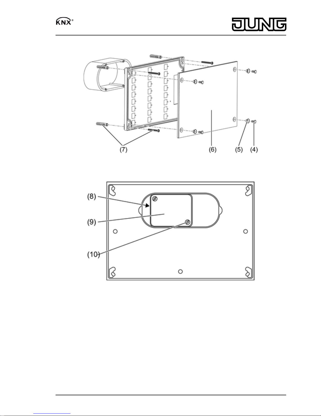
Figure 2: Installation – Overview
Figure 3: Rear view
3/7
82575503
J:0082575503
07.12.2010
Signal panel
Page 4

Figure 4: Connection box opened
(5) Screw sleeve
(6) Front plate
(7) Screws/anchor set
(8) Connection box
(9) Lid of the connection box
(10) Lid screw
(11) Cable penetration
(12) Power supply connection, yellow/white connector
(13) Bus connection, red/black connector
Recommended installation height: 1.50 m.
Installation only using deep concealed appliance box, double.
Only for horizontal installation.
Only install on flat walls.
i Soiling in the slots on the front plate, e.g. due to unsuitable pins or paper strips, cannot be
removed. The labelling of the sensor areas must be able to resist wipes and moisture and
must be made on suitable media, e.g. transparent film.
Recommendation: Use two layers of transparent film and label the inner side (figure 5).
Figure 5: Labelling with two layers of transparent film
4/7
82575503
J:0082575503
07.12.2010
Signal panel
Page 5

o Mark the installation location using the enclosed template. Install the concealed appliance
box, anchor holes for screw fastening Ø = 6 mm.
o Slacken the fastening screws (4) with the enclosed tool – two-hole spanner bit SP-4 – and
remove the front plate (6).
o Slacken the lid screws (10) on the connection box (8) and remove the lid (9).
o Run the connecting cables through the openings (11) of the connection box.
o Connect the bus wires with the red and black bus terminal to the bus connection (13).
o Connect the power supply with the yellow and white terminal to the connection (12).
i The second wire pair of the bus cable can be used to provide the power supply.
o Close the lid (9).
i The physical address must be noted on the device. If possible load the physical address
into the device before final mounting (see chapter 5.2. Commissioning).
o Place the device in the concealed box and screw it to the substrate. Use the enclosed
screw/anchor set (7).
o Push the written push-in labels into the top of the intended slots on the rear side of the front
plate.
o Attach the front plate. Insert the screw sleeves (5) and fasten them to the housing using the
fastening screws (4). Max. torque: 0.5 Nm.
5.2 Commissioning
Loading the physical address and application software
The device is connected and ready for operation.
The power supply and bus voltage are switched on.
o Press the top left and right sensor areas simultaneously.
The programming LED on the right edge of the panel (3) lights up.
o Assign physical address.
The programming LED goes out.
o Load the application software into the device.
o Note the physical address on the labels on the rear side of the device and behind the front
plate.
Checking the LED function
The device is connected and ready for operation.
o Press the top left and bottom right sensor areas simultaneously.
All the LEDS light up in sequence for 2 seconds each in red, green and blue.
6 Appendix
6.1 Technical data
External supply
Rated voltage AC/DC 24 V SELV
Rated frequency 50 / 60 Hz
Power consumption max. 2.2 W
Connection of power supply Connection terminal
Single stranded 0.6 ... 0.8 mm²
Front plate
Dimensions W×H×D approx. 236x156x14 mm
Installation depth approx. 39 mm
Push-in labels
Dimensions L×W approx. 132×39.5 mm
Ambient conditions
Ambient temperature -20 ... +70 °C
Storage/transport temperature -20 ... +75 °C
5/7
82575503
J:0082575503
07.12.2010
Signal panel
Page 6

Relative humidity 15 ... 95 % rel. humidity (No moisture
condensation)
Protection rating IP 54
Safety class III
KNX
KNX medium TP 1
Commissioning mode S-mode
Rated voltage KNX DC 21 ... 32 V SELV
Connection, Bus Connection terminal
Current consumption KNX max. 5 mA
6.2 Troubleshooting
The programming LED flashes green, the device has no function.
The device has not been programmed.
Load the application software into the device.
When operated, functions are only triggered after a delay or not trigged at all.
The device adjusts the detection characteristics regularly. Long actuation of one or more sensor
areas – e.g. for cleaning or during installation – may cause the detection system to become less
sensitive.
The detection characteristics will automatically readjust to normal conditions after a short
time without operation.
Only ever press one sensor area.
6.3 Accessories
Power supply AC 24 V ~ Art.-No.: WSSV10
Power supply 320 mA Art.-No.: 2005 REG
Power supply 640 mA Art.-No.: 2002 REG
Two-gang appliance box, e.g. Kaiser, Art. no. 9062-02
JUNG Labelling tool – www.jung-label.de
6.4 Warranty
We reserve the right to make technical and formal changes to the product in the interest of
technical progress.
We provide a warranty as provided for by law.
Please send the unit postage-free with a description of the defect to our central customer
service office:
ALBRECHT JUNG GMBH & CO. KG
Service Center
Kupferstr. 17-19
D-44532 Lünen
Service-Line: +49 (0) 23 55 . 80 65 51
Telefax: +49 (0) 23 55 . 80 61 89
mail.vka@jung.de
General equipment
Service-Line: +49 (0) 23 55 . 80 65 55
Telefax: +49 (0) 23 55 . 80 62 55
mail.vkm@jung.de
KNX equipment
Service-Line: +49 (0) 23 55 . 80 65 56
Telefax: +49 (0) 23 55 . 80 62 55
mail.vkm@jung.de
The Πsymbol is a free trade symbol, which is solely intended for the authorities and does not
guarantee any properties.
6/7
82575503
J:0082575503
07.12.2010
Signal panel
Page 7

ALBRECHT JUNG GMBH & CO. KG
Volmestraße 1
D-58579 Schalksmühle
Telefon: +49.23 55.8 06-0
Telefax: +49.23 55.8 06-1 89
E-mail: mail.info@jung.de
Internet: www.jung.de
www.jung-katalog.de
7/7
82575503
J:0082575503
07.12.2010
Signal panel
 Loading...