

Page 1
Presence detector mini standard, Presence detector mini universal
Presence detector mini standard
Art. No. : 3361MWW-01
Presence detector mini universal
Art. No. : 3361-1MWW-01
Operating instructions
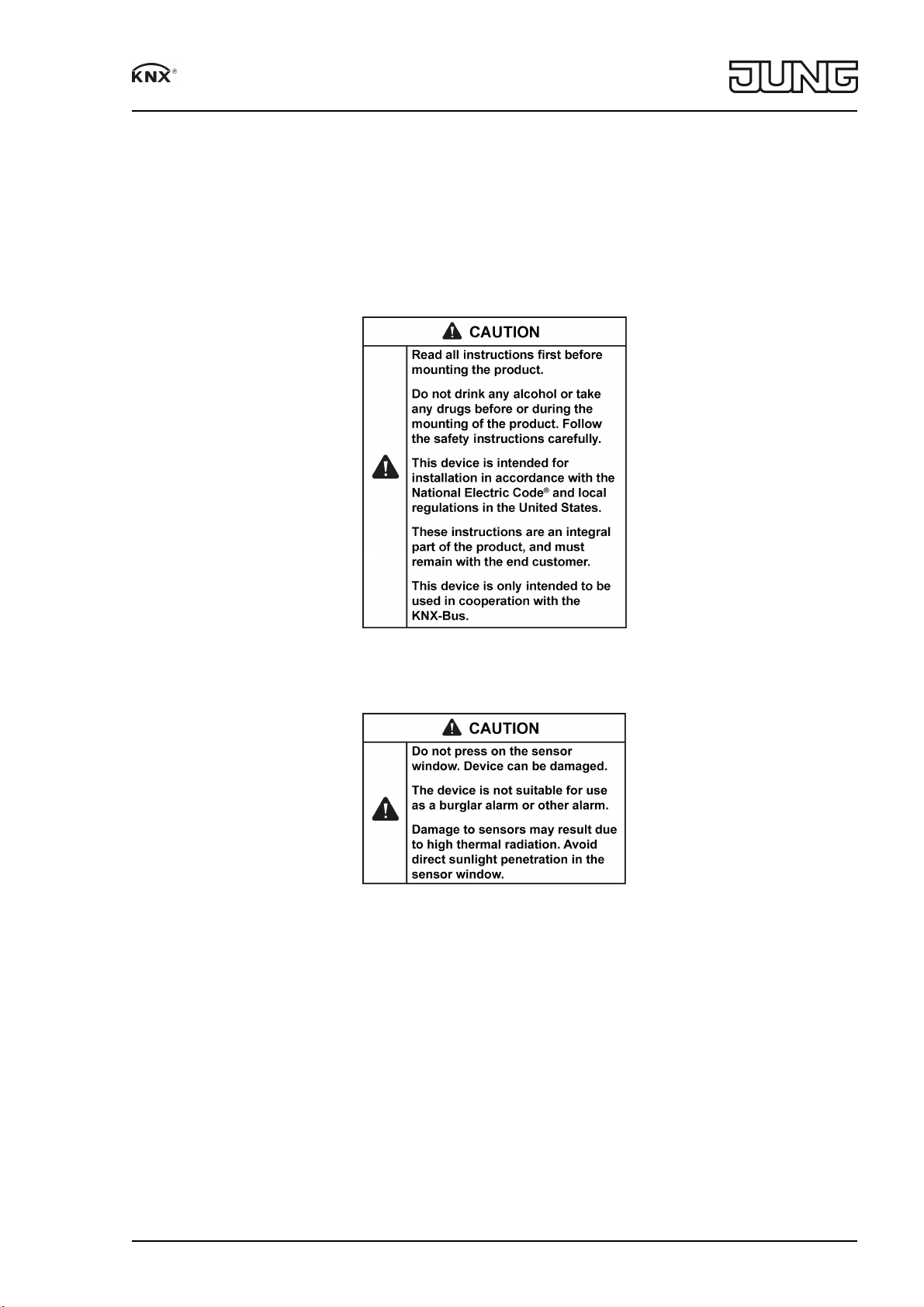
1 Safety instructions
82589805
J0082589805
1/16
09.11.2017
Page 2
Presence detector mini standard, Presence detector mini universal
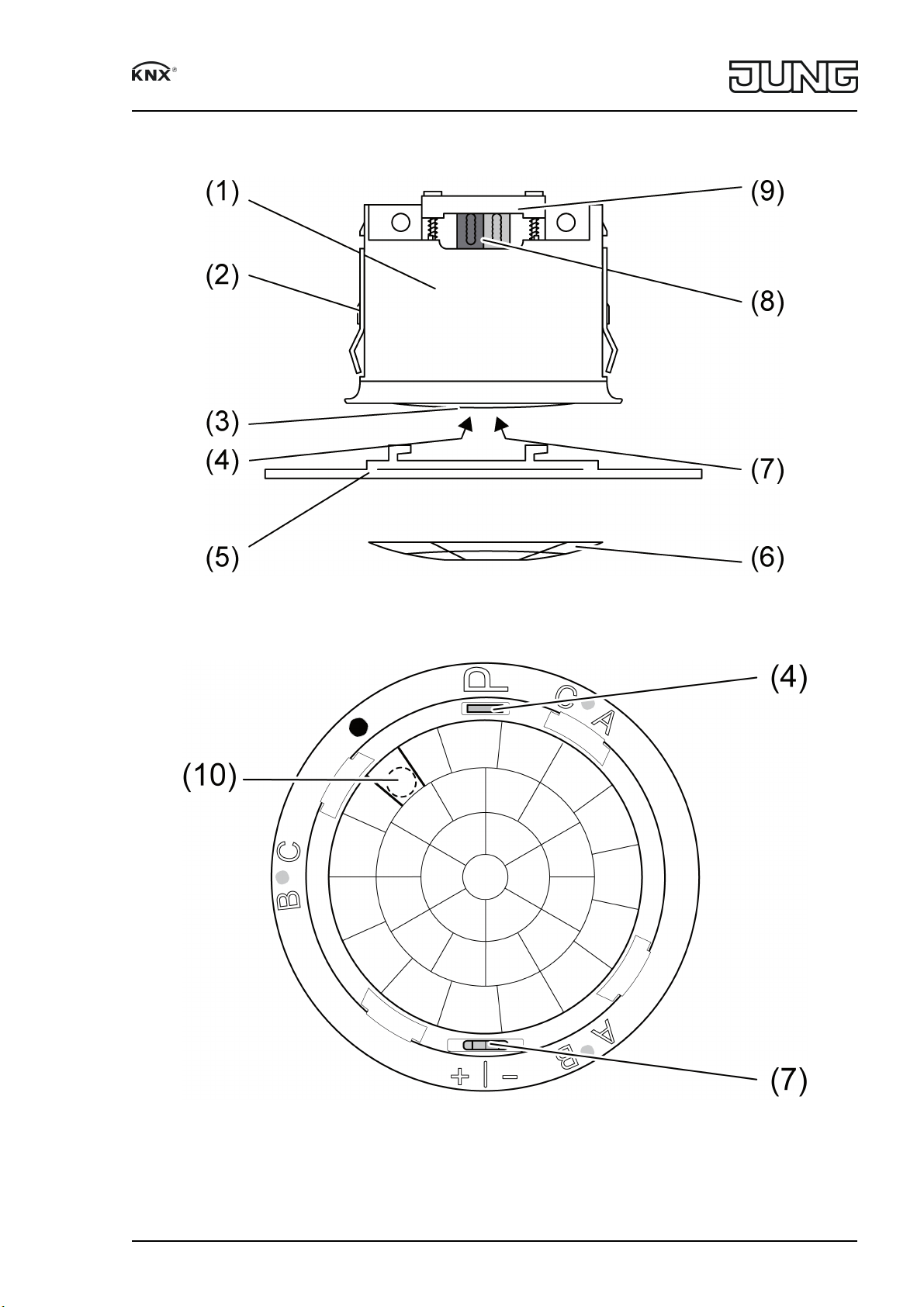
2 Device components
Figure 1: Device components
(1) Presence detector
(2) Clamping springs
(3) Sensor window
82589805
J0082589805
Figure 2: Device components
2/16
09.11.2017
Page 3

Presence detector mini standard, Presence detector mini universal
(4) Programming button, red
(5) Design ring
(6) Cover
(7) Sensitivity switch, blue
(8) Bus connection
(9) Cable fixation
(10) Brightness sensor
3 Function
System information
This device is a product of the KNX system and complies with the KNX directives. Detailed
technical knowledge obtained in KNX training courses is a prerequisite to proper understanding.
The function of this device depends upon the software. Detailed information on loadable soft
ware and attainable functionality as well as the software itself can be obtained from the
manufacturer´s product database. Planning, installation and commissioning of the device are
carried out with the aid of KNXcertified software. The latest versions of product database and
the technical descriptions are available on our website.
Intended use
Requirementoriented control of lighting, room thermostats and other electrical consumers
in interior rooms
Ceiling mounting on fixed ceilings in applicable Listed electrical box or surfacemounted
housing (see accessories)
Presence detector function:
Detection of the smallest motions e.g. at a workplace for detecting the presence of persons
Switch on: Motion detection and brightness threshold not reached
Switch off: No motion in the detection field and runontime elapsed or brightness threshold
exceeded
Motion detector function:
Detection of motions for passageway security in buildings
Switch on: Motion detection and brightness threshold not reached
Switch off: No motion in the detection field and runontime elapsed
i After reacting and switching on, the motion detection works brightnessindependently.
Alert operation:
Brightnessindependent detection of motions in the detection field
Switch on: After detection of an adjustable number of motions within the set monitoring
period
Switch off: No persons in the detection field and runontime elapsed
4 Operating Control
Only for "Universal" version:
Function buttons IR remote control
Button Function
¿ Detection of a motion is sent for function block
1. The automatic mode is exited.
Á End of a motion is sent for function block 1.
The automatic mode is exited.
À The automatic mode is activated again for
function block 1.
The ON status is first exited after a new
motion detection.
82589805
J0082589805
3/16
09.11.2017
Page 4

Presence detector mini standard, Presence detector mini universal
Setting buttons IR remote control
Button Function
´ Increase sensitivity
² Reduce sensitivity
³ Reset sensitivity to presetting
Ê Function block 1: brightness threshold 1 fc
Ë Function block 1: brightness threshold 4.7 fc
Ì Function block 1: brightness threshold 14 fc
Í Function block 1: brightnessindependent
operation
É Function block 1: Set current brightness as
brightness threshold
10 SEK, 30 SEK, 2 MIN, 5 MIN, 30 MIN Function block 1: Extend minimum runontime
(10 seconds) by the selected value
START, STOP Function block 1: Extend minimum runontime
(10 seconds) individually
Set-up buttons, IR remote control
Button Function
Ù Walking test – Check detection field
Ú Reset sensitivity, brightness threshold and
runontime to presetting. Press for at least 3
seconds
Operation with IR remote control
If enabled, function block 1 can be operated manually by remote control. In manual operation,
brightness and motion detection for function block 1 are switched off until automatic mode is
reset.
o Switch on, e.g. light: Press ¿ button.
o Switch off, e.g. light: Press Á button.
o Set automatic mode: Press À button.
Manually change settings with IR remote control
If enabled, individual settings for function block 1 can be changed during operation using a
remote control.
Sensitivity:
o Increase sensitivity: Press ´ button.
o Decrease sensitivity: Press ² button.
o Recall set sensitivity: Press ³ button.
i The manual adjustment of sensitivity by the sensitivity switch (7) is overwritten by the IR
remote control and vice versa.
Brightness threshold:
o Change brightness threshold: Depending on requirement, press Ê button, Ë button, Ì
button or Í button.
o Set current brightness as brightness threshold: Press É button.
Runontime: The preset runontime of 10 seconds can be extended individually.
82589805
J0082589805
4/16
09.11.2017
Page 5
Presence detector mini standard, Presence detector mini universal
o Extend runontime: Depending on requirement, press 10 SEK button, 30 SEK button, 2
MIN button, 5 MIN button or 30 MIN button. Other values can be set with the START/STOP
buttons.
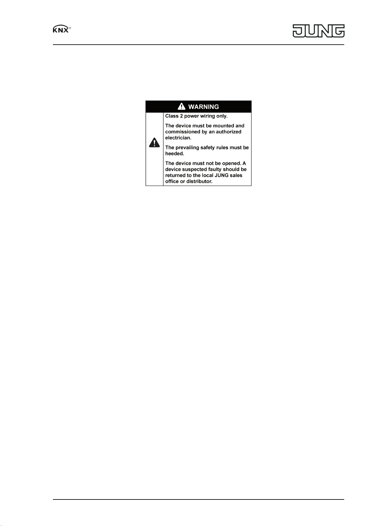
5 Information for electrically skilled persons
82589805
J0082589805
5/16
09.11.2017
Page 6

Presence detector mini standard, Presence detector mini universal
5.1 Mounting and electrical connection
Motion detection
Figure 3: Tangential and radial direction of motion
The device has a detection area of 360°. The diameter of the detection area depends on the
installation height and the direction of motions of persons in the detection area (figure 4).
The detection area becomes larger the greater the installation height, while the detection densi
ty and sensitivity are reduced at the same time.
82589805
J0082589805
6/16
09.11.2017
Page 7

Presence detector mini standard, Presence detector mini universal
Figure 4: Detection range depending on the direction of movement
Diameter of detection field for direction of movement
Installation
1: 2: 3: 4:
height
7.20 ft 28.90 ft 21.70 ft 14.40 ft 9.50 ft
8.20 ft 32.80 ft 24.60 ft 16.40 ft 10.80 ft
9.80 ft 39.40 ft 29.50 ft 19.70 ft 13.10 ft
11.50 ft 42.70 ft 31.20 ft 23.00 ft 15.40 ft
13.10 ft 45.90 ft 32.80 ft 24.60 ft*) – *)
16.40 ft 55.80 ft 36.10 ft 26.30 ft*) – *)
1: Range for tangential movement on the ground
2: Range for radial movement on the ground
3: Range for typical movements at desks, e.g. torso movement
4: Range of fine detection at desks, e.g. mouse movements
*) When used as a presence detector: Mounting height should not be more than 11.50 ft, oth
erwise fine detection is not possible.
The device has three independent sensors for motion detection. The arrangement of the sensor
areas A, B and C is clearly evident under the decor ring (figure 6).
i If the sensor areas A, B, C are evaluated separately, the project design must take the
alignment of the device into account (see chapter Aligning the device).
82589805
J0082589805
7/16
09.11.2017
Page 8

Presence detector mini standard, Presence detector mini universal
Figure 5: Detection field areas A, B and C, installation height 9.80 ft
82589805
J0082589805
8/16
09.11.2017
Page 9

Presence detector mini standard, Presence detector mini universal
Figure 6: Arrangement of the areas A, B and C
Brightness detection
The brightness sensor (8) is attached on the side and thus enables an asymmetric measuring
surface. In this way, for example, it is possible to include several work places in the measure
ment without any laterally entering light distorting the measurement.
82589805
J0082589805
9/16
09.11.2017
Page 10

Presence detector mini standard, Presence detector mini universal
Figure 7
Installation height H R1 R2
7.20 ft 4.90 ft 7.60 ft
8.20 ft 5.90 ft 8.50 ft
9.80 ft 6.60 ft 9.80 ft
11.50 ft 8.20 ft 11.80 ft
13.10 ft 9.20 ft 13.80 ft
16.40 ft 11.50 ft 17.10 ft
Light falling directly onto the sensor or reflected by shiny surfaces influences the brightness
detection.
Select mounting location
When used as a presence detector, the device is installed on the ceiling and monitors the sur
face below it. When used as a motion detector, the device is installed e.g. in the hallway on the
ceiling.
o Select a vibrationfree installation location. Vibrations can lead to unwanted switching.
o Avoid interference sources in the detection area. Interference sources, e.g. heaters, venti
lation, air conditioners, and cooling light bulbs can lead to unwanted detections.
i If necessary, the detection field can be limited using the pushon cover in order to minimize
the influence of interference sources.
Align the device
o When mounting, align the device so that the brightness sensor (10) is not facing the
window (figure 7).
i Already pay attention to correct alignment when mounting the appliance box and support
ing frame.
82589805
J0082589805
10/16
09.11.2017
Page 11

Presence detector mini standard, Presence detector mini universal
Mount the device in a wall box and connect it
This device may only be installed in applicable listed electrical wall boxes, flushmounted.
i Wall boxes must be ordered separately.
o Wall boxes for solid walls have to be placed flush to the wall plaster.
o Hollow wall boxes were placed by circular cutter. A hole of dia. 2.67 in (68 mm) must be
made.
The wall box will be plugged into and screwed by integrated clamps.
Wall box (11) is mounted on the ceiling at the designated installation location.
82589805
J0082589805
11/16
09.11.2017
Page 12

Presence detector mini standard, Presence detector mini universal
Figure 8
o Mount supporting frame (12) on a wall box (11).
i Use only cables which are approved for KNX.
o Connect bus line with device connection terminal.
o Clamp bus line with cable fixation (9).
o Snap the device into the supporting frame (12).
o Attach the large design ring (5) and rotate it in a clockwise direction.
o If required: Cut out the cover (6) and clip it into the design ring (5).
82589805
J0082589805
12/16
09.11.2017
Page 13
Presence detector mini standard, Presence detector mini universal
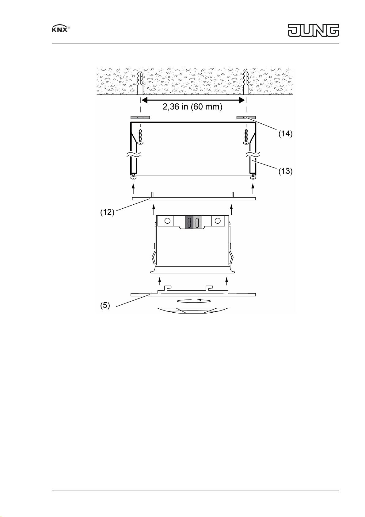
Mount and connect device in a surface-mounted housing
Figure 9
Use a surfacemounted housing (13) (see accessories).
o Provide screw holes of the surfacemounted housing with the supplied seals (14).
o Seal the cable entry with the supplied rubber grommet. Cut the rubber grommet appropri
ately for the bus cable. Route the bus line into the surfacemounted housing.
o Mount the surfacemounted housing (13) on the room ceiling at the designated installation
location. Hole spacing 2.36 in.
o Mount the supporting frame (12) on the surfacemounted housing (13).
i Use only cables which are approved for KNX.
o Connect bus line with device connection terminal.
o Clamp bus line with cable fixation (9).
o Snap the device into the supporting frame (12).
o Attach the large design ring (5) and rotate it in a clockwise direction.
o If required: Cut out the cover (6) and clip it into the design ring (5).
82589805
J0082589805
13/16
09.11.2017
Page 14

Presence detector mini standard, Presence detector mini universal
5.2 Commissioning
Load the address and the application software
o When mounted, remove the design ring.
o Switch on the bus voltage.
o Actuate the red programming button (4).
The programming LED in the sensor window lights up.
o Assign physical address.
The programming LED goes out.
o Label device on the side with physical address.
o Load the application software into the device.
Test the detection area
In the case of presence detectors connected in parallel, check the detection areas individually
one after the other.
The presence detector is mounted and connected. The physical address and application soft
ware are loaded.
o Activate walking test:
Activate parameter "walking test after download" and download application software.
The presence detector operates independently of the brightness. All sensors are active
according to their programmed sensitivity.
o Pace off the detection area, paying attention to reliable detection and interference sources.
Any motions detected are displayed by the blue status LED in the sensor window.
o Limit detection area if necessary using the pushon cover. Adjust sensitivity with blue sen
sitivity switch (7) or IR remote control, or change the programming.
o Deactivate parameter "walking test after download" and download application software.
Only for "Universal" version:
i If enabled, the walking test function can be activated with the button Ù of the IR remote
control.
6 Appendix
Disposal
Please consider your local regulation for disposal and electronic waste recycling.
6.1 Technical data
KNX medium TP
Commissioning mode S-mode
Rated voltage KNX DC 21 ... 30V SELV
Current consumption KNX max. 10mA
Connection, Bus device connection terminal
Protection class III
Ambient temperature -13 ... +131°F
(-25 ... +55 °C)
Storage/transport temperature -13 ... +158°F
(-25 ... +55 °C)
Relative humidity 10 ... 100% (No moisture condensation)
Dimensions
Ceiling cutout Dia.×D 1.73 × 1.4 in
(44 × 35 mm)
Dimension dia.×H 2.11 × 1.5 in
(53.5 × 38 mm)
Motion detection
Detection angle 360°
82589805
J0082589805
14/16
09.11.2017
Page 15

Presence detector mini standard, Presence detector mini universal
Range at installation height 9.8 ft (3 m) Ø approx. 39.4 ft
(dia. approx. 12 m)
Brightness sensor
Measuring range 1 ... 186 fc
(10 ... 2000 lx)
Accuracy ≤ 7.5 fc (≤ 80 lx) ± 1 fc (± 10 lx)
Accuracy > 7.5 fc (> 80 lx) ± 5%
Purpose of control Sensing Control
Construction of control Independently Mounted Control for Surface
Mounting
Pollution Degree PD 2
Impulse Voltage 330V
6.2 Troubleshooting
Light does not switch on despite motion detection and low lighting
Cause 1: Wrong function block active.
Change function block switchover.
Cause 2: Brightness threshold set is too low.
Increase the brightness threshold with the remote control or parameter setting.
Light switches on despite sufficient ambient lighting
Cause 1: Signal function is active and the device therefore operates independently of the bright
ness.
Check programming.
Cause 2: Device operates independently of the brightness.
Adjust the brightness threshold with the remote control.
Correct parameter setting for brightness threshold.
Light switches off briefly and then on again immediately
Cause 1: Luminaires in the detection area.
Set the configuration barrier parameter so that cooling luminaires are not detected.
Cause 2: The brightness threshold set is not reached after switching off. Device switches on
again immediately during motion detection.
Increase brightness threshold.
Light switches off early despite motion detection and low lighting
Cause 1: The set time is too short.
Increase the time with the remote control or parameter setting.
Cause 2: Detection problem, the surface to be monitored is not in the detection area, or furni
ture or pillars are in the way.
Check detection field, extend presence detector extension if necessary.
Device responds even without any motion in the detection field
Cause: Interference sources in the detection area or device are set too sensitively.
Limit detection area, remove interference sources.
Adjust sensitivity by one level with blue sensitivity switch (7) or with remote control.
Reduce sensitivity in parameter setting.
i The sensitivity should be reduced by 1 to 2 levels in small spaces.
Light does not switch off despite sufficient ambient lighting
Cause 1: Device is set as motion detector and therefore does not evaluate the ambient lighting
after reacting.
Check programming. Set and program device as presence detector.
82589805
J0082589805
15/16
09.11.2017
Page 16

Presence detector mini standard, Presence detector mini universal
Cause 2: Brightness threshold is set too high.
Decrease the brightness threshold with the remote control or parameter setting.
Light does not switch on or switches on too late despite motion in the detection field
Cause 1: Device is set for alert operation and does not evaluate the first motion impulse detect
ed.
Check programming. Set and program device as motion detector.
Cause 2: Evaluation delay is activated so that anyone briefly entering the detection area,
for example, is not evaluated.
Correct the programming, shorten or deactivate evaluation delay.
6.3 Accessories
Flush mounting set Order No. PMMUPSETWW
Surface mounting set Order No. PMMAPSETWW
IR remote control Order No. KNXPMFBIR
6.4 Warranty
If you have any questions about this product, contact:
Jung USA, Inc.
350 Fifth Avenue, Suite 5220
New York, NY 10118
Phone: +1 800.311.6135
Email: sales@jungcontrols.com
www.jungcontrols.com
For the product warranty, please refer to the attached document.
All rights reserved
©
ALBRECHT JUNG GMBH & CO. KG
Volmestraße 1
58579 Schalksmühle
GERMANY
82589805
J0082589805
16/16
09.11.2017
 Loading...