

Page 1
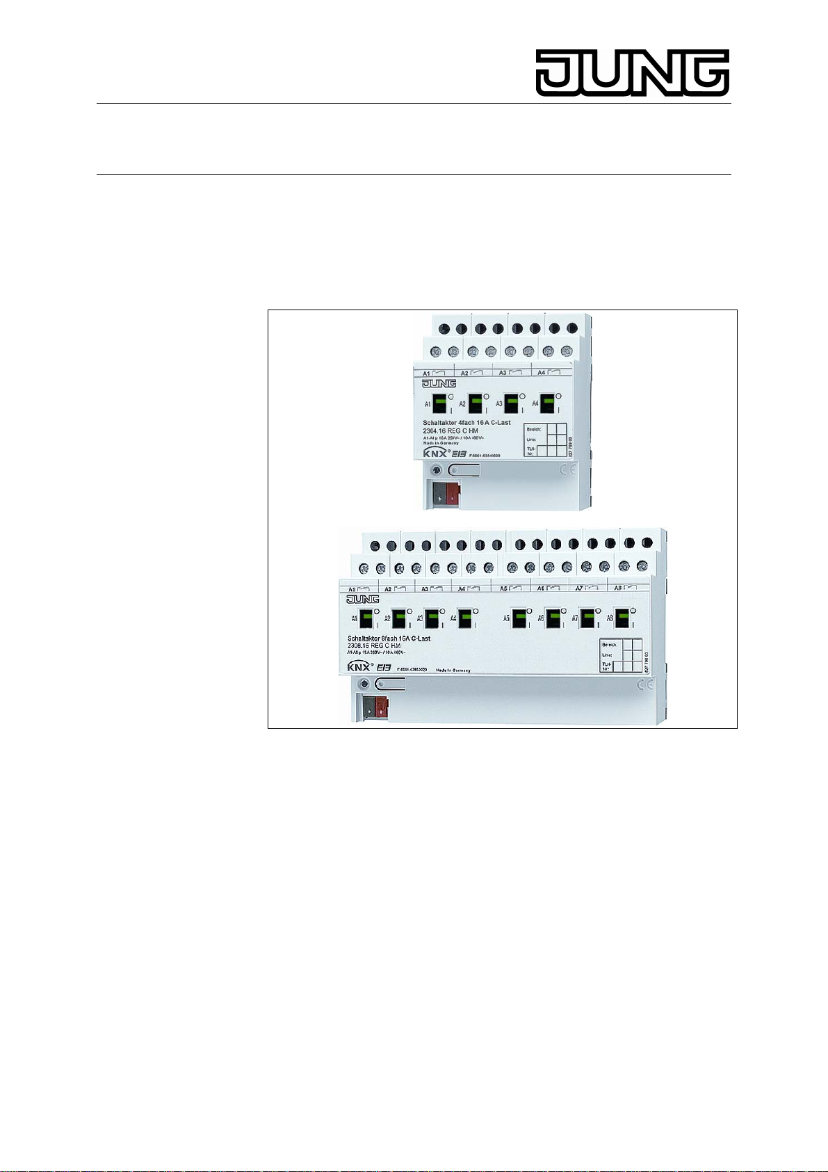
KNX 4-/8-channel switching actuator 16A
4-/8-channel switching actuator 16A / C-load
Art.-Nr.: 230x.16 REGHM, 230x.16REGCHM
Operation Instructions
4-/8-channel switching actuator 16A
4-/8-channel switching actuator 16A /
C-load with current detection
1. Safety instructions
Electrical equipment must be installed and fitted by qualified
electricians only. Observe the current accident prevention
regulations. Failure to observe the instructions may cause damage
to the device and result in fire or other hazards. The device is not
suited for safe disconnection of the mains supply. Do not connect
mains voltage consumers together with SELV/ PELV consumers to
the same switching actuator. Do not connect three-phase AC
motors to the actuator. The current detection and load monitoring
functions must not be used for safety-related applications, e.g.
overload detection. These operating instructions are part of the
product and must be left with the final customer.
Stand: Mai-07 825 603 03
2. System information
This device is a product of the KNX-system and complies with KNX
directives. Technical knowledge obtained in KNX training courses is a
prerequisite to proper understanding. The functionality of this device
depends on the software. Detailed information on loadable software and
Page 2

KNX 4-/8-channel switching actuator 16A
4-/8-channel switching actuator 16 A / C-load
Art.-Nr.: 230x.16 REGHM, 230x.16REGCHM
attainable functionality as well as the software itself can be obtained from
the manufacturer’s product database. Planning, installation and
commissioning of the unit is effected by means of KNX-certified software.
The full functionality with KNX commissioning software from version
ETS3.0d. onwards. The product database, technical descriptions and
conversion programs and other utilities are available in the Internet at
www.jung.de.
3. Designated use
Switching of electrical consumers AC 230 V or 24 V AC/DC with
potential-free contacts
Mounting on DIN rail in fixed installations (power distributions or
small boxes).
4-channel and 8-channel switching actuators for C-loads
Switching of capacitive loads with resulting higher inrush currents
3.1. Product features
Bus-independent manual switching of relays
Operation as n.c. or n.o. contacts
Logic operation and forced-control functions
Switching checkback mode
Switching status indicator and manual switching
Central switching function with group checkback
Inhibit function for each channel
Time functions: ON-delay, OFF-delay, staircase lighting timer
with early-warning function
Incorporation in light-scenes
Operating hours counter, bus-configurable
Input monitoring for cyclical updates with safety circuit
No additional power supply
L Actuator relay outputs switching with short time delay after actuation
via central telegram.
Additional properties of the C-load switching actuators
Current detection: measurement of load current for each channel
Threshold values for load monitoring, e.g. load failure message
2
Page 3
KNX 4-/8-channel switching actuator 16A
4-/8-channel switching actuator 16 A / C-load
Art.-Nr.: 230x.16 REGHM, 230x.16REGCHM
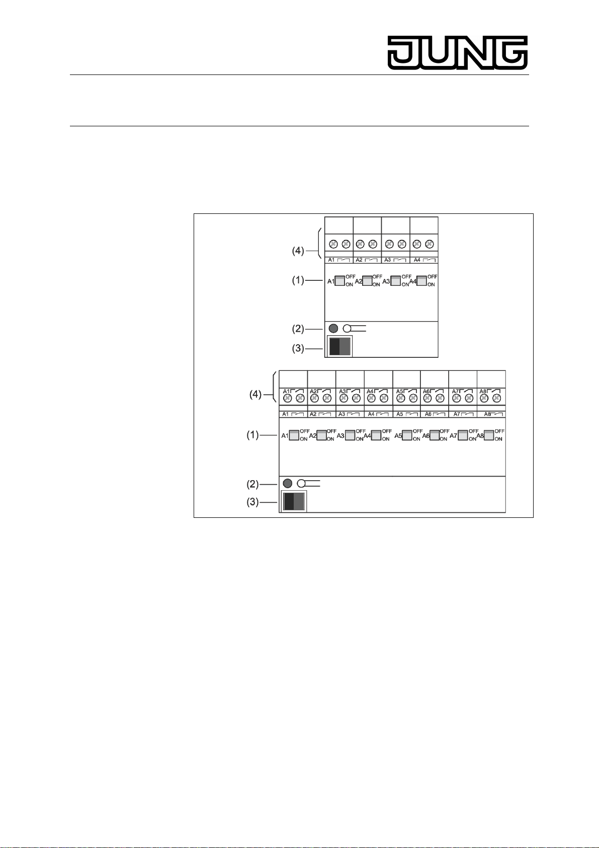
4. Manual operation
The switching state of the relays is indicated by the switching position
indicators (1) on the front panel The indicators can be used at the same
time for manual switching of the relay outputs.
Fig. 1
(1) switching status indicators / manual switching
(2) programming button and LED
(3) KNX terminal
(4) relay output terminals
Slide switching position indicator (1) into the ON position. The
relay contact is closed and the consumer is activated.
Slide switching position indicator (1) into the OFF position The
relay contact is open and the consumer is deactivated.
L The switching position indicator shows directly the state of the relays
independently of the mode of operation of the output (n.o. or n.c.
contact)
L Manual relay switching independent of the bus. No checkback via the
bus for manual switching.
L Software-disabled outputs can be switched manually.
3
Page 4

KNX 4-/8-channel switching actuator 16A
4-/8-channel switching actuator 16 A / C-load
Art.-Nr.: 230x.16 REGHM, 230x.16REGCHM
Information for qualified electricians
5. Installation and electrical connection
DANGER
Electric shock in case of accidental contact with live parts. Electric
shocks may be fatal. Before working on the device, disconnect the
mains voltage and cover up live parts in the surroundings.
5.1. Installation of the device
Observe the admissible temperature range. Ensure sufficient cooling.
Snap the device onto a DIN EN 60715 mounting rail. The
connecting terminals must be at the top.
5.2. Connection of the device
Observe the admissible loads.
L Do not connect three-phase AC motors to the actuator.
L On delivery, the switching state is undefined.
Set the relays to the OFF position.
Connect as shown in the example (Fig. 2).
Fig. 2
Connect the bus with the bus terminal (Fig. 1, 3).
L The connection to different phase conductors is possible.
L For current detection, the device is equipped with contactless current
sensors. Magnetic fields in the immediate vicinity can result in false
current measurement results. If possible, lay feed and return line
closely side by side. Do not install devices producing magnetic fields in
the immediate vicinity of the actuator, e. g. doorbell transformer, power
contactor, etc.
4
Page 5

KNX 4-/8-channel switching actuator 16A
4-/8-channel switching actuator 16 A / C-load
Art.-Nr.: 230x.16 REGHM, 230x.16REGCHM
5.3. Sliding on the protective cap
To protect the bus lines against dangerous voltages at the connecting
terminal, slide on the protective cap.
Lead out the bus line at the rear of the device.
Slide the cap over the bus terminal (Fig. 3 A) until it is heard to
engage.
5.4. Removing the cap
Press the sides of cap and withdraw (Fig. 3 B).
6. Commissioning
Switch on the bus voltage
Assign a physical address and download the application software
(with commissioning software).
Switch on the mains voltage at the outputs.
5
Page 6

KNX 4-/8-channel switching actuator 16A
4-/8-channel switching actuator 16 A / C-load
Art.-Nr.: 230x.16 REGHM, 230x.16REGCHM
7. Technical Data
Medium: TP1
Mode of commissioning: S-Mode
KNX supply: 21...32 V DC
KNX connection: Connecting terminals
Connection of outputs: Screw terminals
solid wire 0.5...4 mm²
stranded wire without ferrule 0.5...4 mm²
stranded wire with ferrule 0.5...2.5 mm²
Screw terminal tightening torque. max. 0.8 Nm
Output contact type. potential-free n.o. contact
(μ-contact)
Ambient temperature: -5 °C...+45 °C
Storage temperature -25 °C...+70 °C
Total dissipated power
4-channel switching actuators. max. 4 W
8-channel switching actuators. max. 8 W
Mounting width
4-channel switching actuators 72 mm (4 modules)
8-channel switching actuators 144 mm (8 modules)
4-channel and 8-channel
KNX power consumption typically 150 mW
Weight:
4-channel switching actuator ca. 220 g
8-channel switching actuator ca. 400 g
4-channel and 8-channel C-load
KNX power consumption typically 240 mW
Current detection (sinus)
Frequency 50/60 Hz
Detection range 0.25...16 A sinus
Detection accuracy < 1 A: ±100 mA
> 1 A: ±8% of actual value
Weight
4-channel switching actuator C-load ca. 270 g
8-channel switching actuator C-load ca. 500 g
6
Page 7

KNX 4-/8-channel switching actuator 16A
4-/8-channel switching actuator 16 A / C-load
Art.-Nr.: 230x.16 REGHM, 230x.16REGCHM
8. Switching capacitiy
7
Page 8

KNX 4-/8-channel switching actuator 16A
4-/8-channel switching actuator 16 A / C-load
Art.-Nr.: 230x.16 REGHM, 230x.16REGCHM
9. Accessoires
Protective cap Art.-no.: 2050 K
10. Help in case of trouble
Operation via the bus impossible
Cause 1: no bus voltage
Switch on the bus voltage; check installation
Cause 2: application software halted, programming LED flashing
Disconnect the device from the bus, reconnect after 5 seconds.
Cause 3:no or faulty application software.
Have the programming checked and rectified.
.
11. Guarantee
Our products are under guarantee within the scope of the statutory
provisions.
Please return the unit postage paid to our central service
department giving a brief description of the fault:
ALBRECHT JUNG GMBH & CO. KG
Service-Center
Kupferstr. 17-19
D-44532 Lünen
Service-Line: +(49) 23 55 . 80 65 51
Telefax: +(49) 23 55 . 80 61 89
E-Mail: mail.vka@jung.de
General equipment
Service-Line: +(49) 23 55 . 80 65 55
Telefax: +(49) 23 55 . 80 62 55
E-Mail: mail.vkm@jung.de
KNX equipment
Service-Line: +(49) 23 55 . 80 65 56
Telefax: +(49) 23 55 . 80 62 55
E-Mail: mail.vkm@jung.de
The
authorities and does not include any warranty of any properties.
-Sign is a free trade sign addressed exclusively to the
8
 Loading...