

Page 1
Universal weather station
Universal weather station
Art. No. : 2225WSU-01
Operating instructions
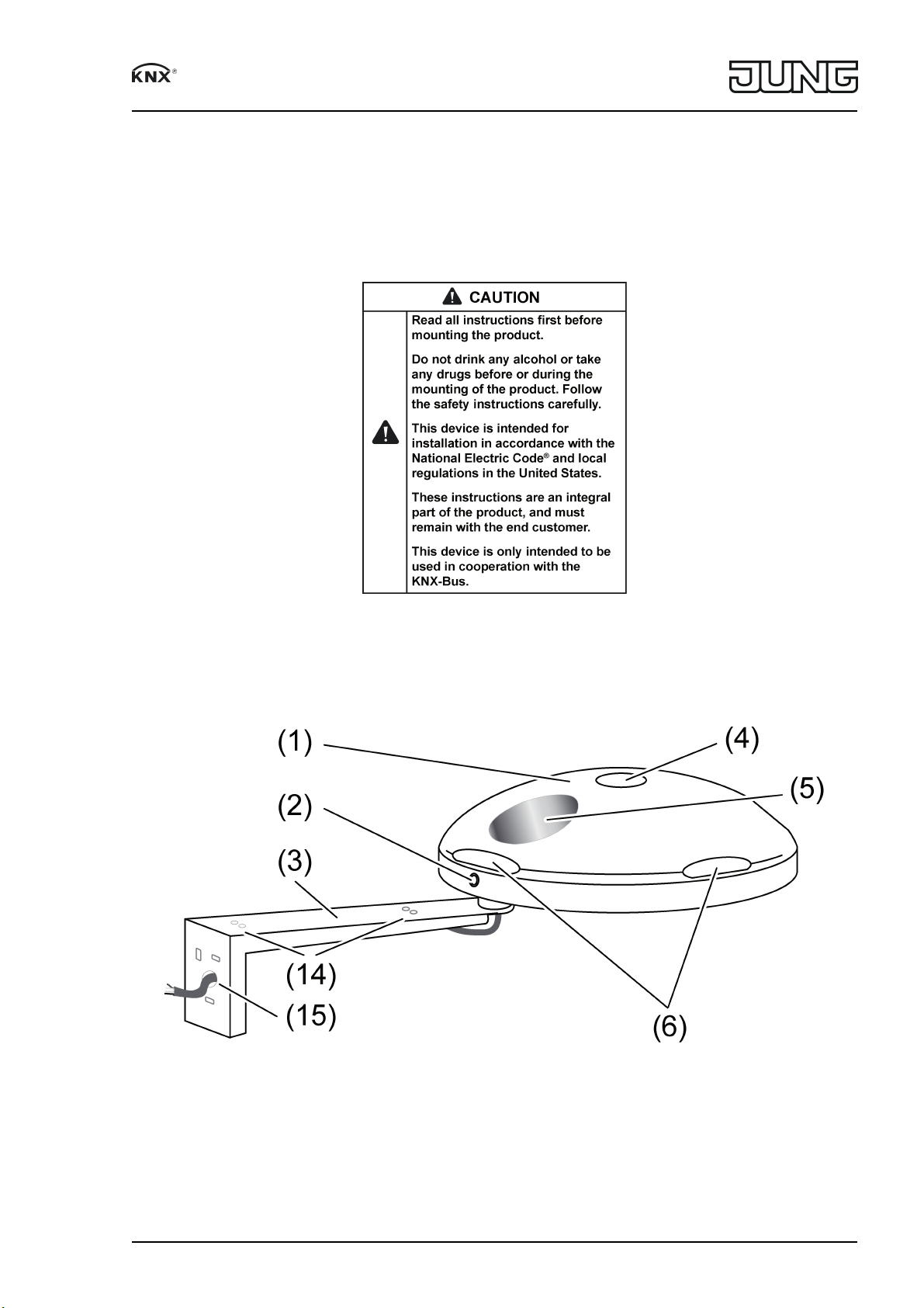
1 Safety instructions
2 Device components
Figure 1: View
82590115
J0082590115
1/10
07.11.2017
Page 2
Universal weather station
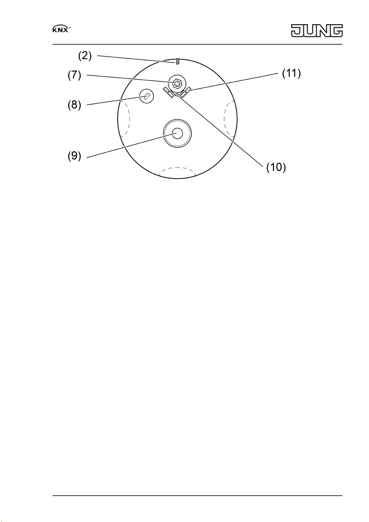
Figure 2: Underside view
(1) Sensor head
(2) Grub screw for locking
(3) Fastening arm
(4) Global radiation sensor
(5) Precipitation sensor
(6) Light and twilight sensors
(7) Mounting for fastening arm with bus connection
(8) Air humidity sensor
(9) Wind speed and wind direction sensor
(10) Temperature sensor
(11) Guide blade
(only if mounted on a mast)
(14) Holes for fastening and strain relief of the connecting cable with cable ties
(15) Cable bushing for connecting cable
3 Function
System information
This device is a product of the KNX system and complies with the KNX directives. Detailed
technical knowledge obtained in KNX training courses is a prerequisite to proper understanding.
The function of this device depends upon the software. Detailed information on loadable soft
ware and attainable functionality as well as the software itself can be obtained from the
manufacturer´s product database. Planning, installation and commissioning of the device are
carried out with the aid of KNXcertified software. The latest versions of product database and
the technical descriptions are available on our website.
Intended use
Measurement and evaluation of weather data: wind speed, wind direction, precipitation,
brightness, global radiation, twilight, temperature, relative air humidity, and air pressure
Operation with NEC Class 2 suitable power supply AC/DC 24 V SELV
Installation on the outside of buildings, preferable in the roof and facade area
i The measured values apply to the mounting location. Variations from other weather ser
vices – e.g., due to local turbulence or areas with buildups of air – are possible.
82590115
J0082590115
2/10
07.11.2017
Page 3
Universal weather station
4 Information for electrically skilled persons
4.1 Mounting and electrical connection
Select mounting location
82590115
J0082590115
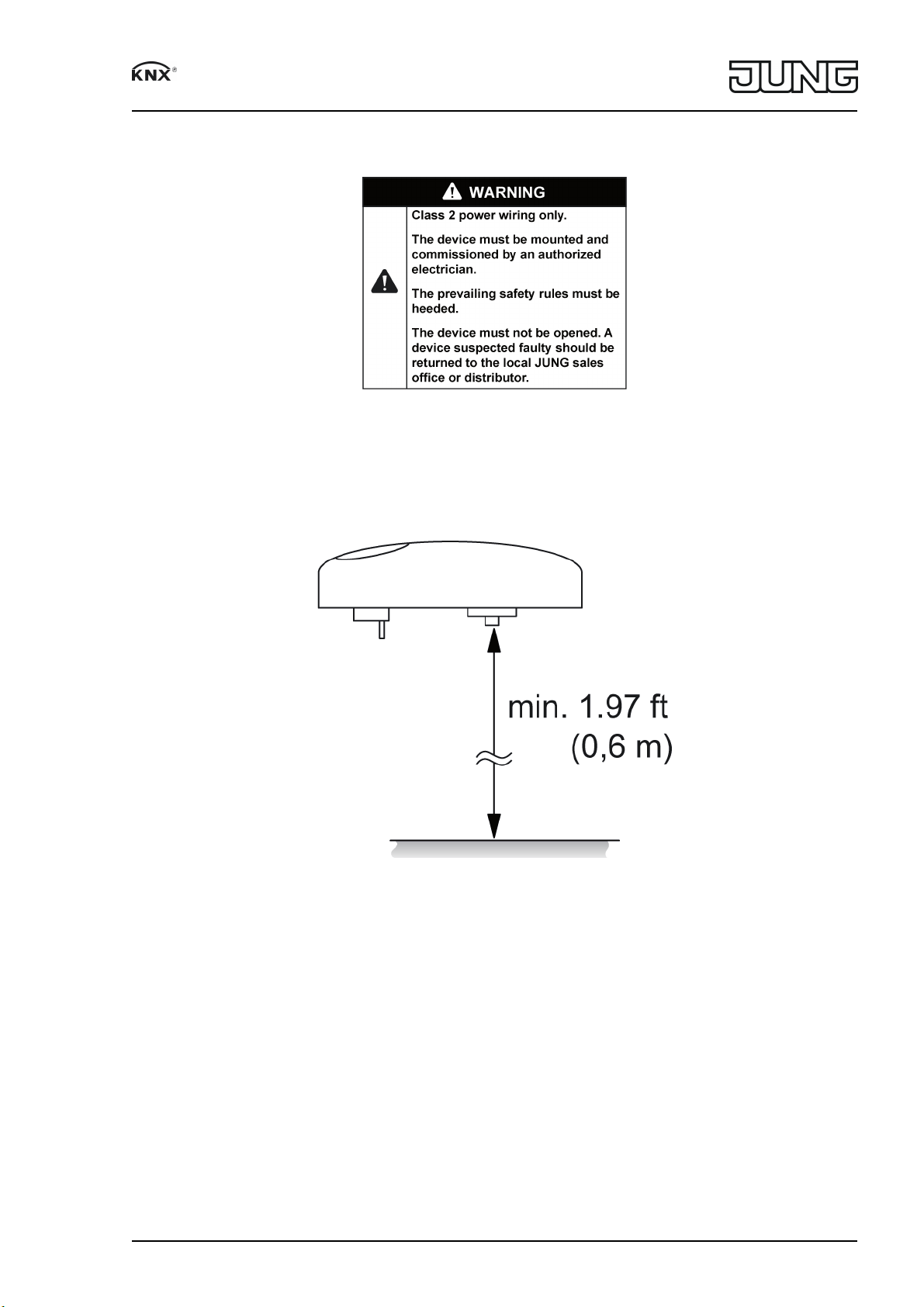
Figure 3: Minimum distance to surfaces
3/10
07.11.2017
Page 4

Universal weather station
Figure 4: Avoid spray water
Figure 5: Maximum load on the fastening arm
Select a mounting location in which the weather station is not influenced by local obstacles or
shading, such as surrounding trees, chimneys, awnings, etc. The sensor must be able to detect
wind, rain, and ambient brightness without impedance. Avoid slipstream, shadow casting, and
light reflection.
Preferred mounting on a freestanding mast. If the device is mounted on house walls, the mea
surement of wind and brightness in particular can be distorted.
Do not mount it below or next to building sections from which water can drip onto the device.
Select the mounting location so that the weather station will be accessible.
In the case of flat roofs, locate the weather station as close to the center of the roof as possible.
Minimum distance to surfaces below the weather station: 1.97 ft (0.6 m)(figure 3). Otherwise,
the sensors on the underside may be damaged by penetrating spray water (figure 4).
Direct sunlight, chimneys, or other waste gas or ventilation systems affect the temperature mea
surement.
Do not operate in the vicinity of radio transmitter systems. Doing so will compromise the func
tion.
i Do not connect more than 3 weather stations in a KNX line.
82590115
J0082590115
4/10
07.11.2017
Page 5

Universal weather station
Mounting a weather station without a fastening arm on a freestanding mast
Figure 6: Mounting on a freestanding mast without a fastening arm
Use mast with outer diameter <0.98 in (25 mm) and inner diameter >0.75 in (19 mm).
o Mount the enclosed guide blade (11) in the fields provided next to the connection (7).
i If mounted on a mast without the guide blade, correct wind direction measurement will not
be possible due to the resulting turbulences.
o Run the connection cable through the mast.
o Attach the 7pin plug to the connection (7). Tighten threaded ring with
max. 0.37 lbf.ft (0.5 Nm).
o Mount the weather station on the mast and align it. The grub screw (2) must be pointing
north.
o Tighten grub screw (2) with max. 0.44 lbf.ft (0.6 Nm).
82590115
J0082590115
5/10
07.11.2017
Page 6

Universal weather station
Mounting a weather station with a fastening arm on a mast or wall
Figure 7: Mounting with fastening arm
Mount enclosed fastening arm onto a suitable mast or wall.
The enclosed hose clamps are suitable for a maximum mast diameter of up to 2.36 in (60 mm).
i When mounting on the supplied fastening arm, do not mount the enclosed guide blade.
o Mast mounting: Attach the fastening arm to the mounting mast using the enclosed hose
clamps.
o Wall mounting: Attach the fastening arm to the wall through the boreholes using three suit
able screws.
o Route the connecting cable along the underside of the fastening arm and guide the 7pin
plug through the open pipe socket at the end of the fastening arm.
o Fit the cable ties for strain relief (14).
o Attach the 7pin plug to the connection (7). Tighten the threaded ring with max.
0.37 lbf.ft (0.5 Nm).
o Mount the weather station on the fastening arm and align it. The grub screw must be point
ing north.
o Tighten the grub screw with max. 0.44 lbf.ft (0.6 Nm).
o Route the connecting cable through the cable bushing (15) into an installation pipe.
82590115
J0082590115
6/10
07.11.2017
Page 7

Universal weather station
Figure 8: Fastening arm – dimensions for boreholes
Mounting and connecting the device
i Use only cables which are approved for KNX.
o Connect the bus line and external power supply to the connecting cable.
red KNX+
Black KNX–
orange AC/DC 24 V ~/+
brown AC/DC 24 V ~/+
i The sensor head is translucent. Therefore, do not stick anything or write on the sensor
head.
82590115
J0082590115
7/10
07.11.2017
Page 8

Universal weather station
Align the device
Figure 9: Orienting the weather station
o Align the sensor head in the appropriate direction or – depending on the detailed onsite
circumstances – according to the alignment of the facade (figure 9).
4.2 Commissioning
Commissioning the device
Figure 10: Position of the programming LED and reed contact
o Switch on the bus voltage.
o Switch on supply voltage.
o Hold the supplied programming magnet by the integrated reed contact (12).
The programming LED (13) indicates the programming state blue.
o Programming the physical address and application program
o Note the physical address on adhesive labels on the underside.
The device is ready for operation.
82590115
J0082590115
8/10
07.11.2017
Page 9

Universal weather station
5 Appendix
Disposal
Please consider your local regulation for disposal and electronic waste recycling.
5.1 Technical data
Supply
Rated voltage AC/DC24 V SELV
(± 10%)
Current consumption 100 ... 400 mA
(dependent on the weather)
Protection class III
Connecting cable
Cable type LiYCY 4xAWG26
Cable length 16.4 ft (5 m)
Total length per line 49.2 ft (15 m)
Number of weather stations max. 3 (per line)
KNX
KNX medium TP
Commissioning mode S-mode
Rated voltage KNX DC 21 ... 30V SELV
Current consumption KNX max. 5mA
Ambient conditions
Housing
Dimensions Ø×H 5.12x2.68 in
(130x68 mm)
Weight ca. 8.11 oz (230 g)
Wind direction sensor
Measuring range 1 ... 360°
Resolution 1°
Accuracy ± 10°
Wind speed sensor
Resolution 0.3 ft/s (0.1 m/s)
Accuracy (≤ 10 m/s) ± 3.3 ft/s (± 1 m/s)
Accuracy (>10 m/s) ± 5%
i Accuracy as RMS average value over 360°.
Temperature sensor
Measuring range -22 ... +140°F
(-30 ... +60 °C)
Resolution 0.1 K
Accuracy ± 1 K (Wind > 6.56 ft/s
(2 m/s), for 23 ... 77°F
(-5 ... +25 °C))
Precipitation sensor
Measuring range yes/no
Accuracy Fine drizzle
Brightness sensors
Number 4
Measuring range approx. 0 ... 13.9 kfc
(0 ... 150 klx)
Resolution 93 fc (1 klx)
Accuracy ± 3%
Spectral range 475 ... 650nm
Twilight sensor
Measuring range approx. 0 ... 83 fc (0 ... 900 lx)
Resolution 0.1 fc (1 lx)
Accuracy ± 1 fc (± 10 lx)
Air pressure sensor
82590115
J0082590115
9/10
07.11.2017
Page 10

Universal weather station
Measuring range 4.35 ... 15.95 psi
(300 ... 1100 hPa)
Resolution 0.00015 psi (0,01 hPa)
Accuracy ± 0.007 psi (± 0,5 hPa) at 68 °F (20 °C)
Humidity sensor
Measuring range 0 ... 100% rel. humidity
Resolution 0.1% rel. humidity
Accuracy ± 10 % rel. humidity at 68 °F (20 °C)
abs. humidity 0 ... 0.4 oz/ft³
(0 ... 400 g/m³)
Resolution 0.00001 oz/ft³ (0,01 g/m³)
Global radiation
Measuring range 0 ... 120 W/ft²
(0 ... 1300 W/ft²)
Resolution 0.1 W/ft² (1 W/m²)
Accuracy ± 10%
Spectral range 350 ... 1100 nm
Purpose of control Sensing Control
Construction of control Independently Mounted Control for Surface
Mounting
Pollution Degree PD 2
Impulse Voltage 330V
i All accuracy specifications relate to the respective measuring range end value.
5.2 Warranty
If you have any questions about this product, contact:
Jung USA, Inc.
350 Fifth Avenue, Suite 5220
New York, NY 10118
Phone: +1 800.311.6135
Email: sales@jungcontrols.com
www.jungcontrols.com
For the product warranty, please refer to the attached document.
All rights reserved
©
ALBRECHT JUNG GMBH & CO. KG
Volmestraße 1
58579 Schalksmühle
GERMANY
82590115
J0082590115
10/10
07.11.2017
 Loading...