

Page 1
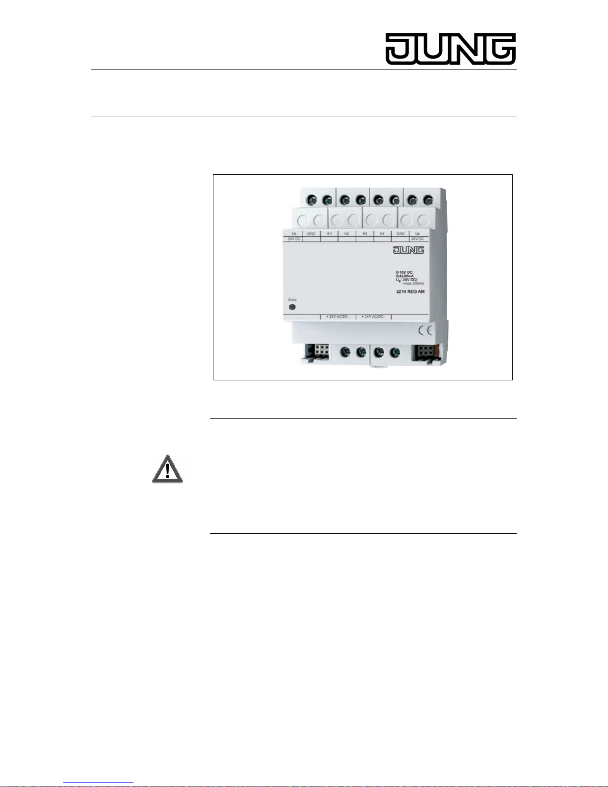
KNX 4-channel analog input module
Ref.-no.: 2214 REG AM
Operating Instructions
4-channel analog input module
1. Safety instructions
Attention:
Electrical equipment must be installed and fitted by qualified
electricians only and in strict observance of the relevant
accident prevention regulations.
Failure to observe any of the installation instructions may result in
fire and other hazards.
U
s
and GND must not be interconnected with the corresponding
terminals of another device.
Connected sensors must not be supplied with power from the
connected KNX/EIB device (Risk of irreparable damage!).
2. Function
• This analog input module extends a KNX/EIB weather station
Art. no. 2224 REG W or a KNX/EIB analog input Art. no. 2114 REG
A by four additional sensor inputs for analog transducers.
• Measuring data evaluation and limit processing take place in the
KNX/EIB device.
• The analog input module accepts both voltage and current signals:
Voltage signals: 0 ... 1 V DC 0 ... 10 V DC
Current signals: 0 ... 20 mA DC 4 ... 20 mA DC
• The current inputs 4 ... 20 mA can be monitored for wire breakage
(parameter setting).
Page 2
KNX 4-channel analog input module
Ref.-no.: 2214 REG AM
3. Installation
The device is snap-fastened on a 35 x 7.5 mm rail as per EN 50022.
An analog input module must be connected to the KNX/EIB device
by means of the 6-pole system connector only (supplied with the
analog input module).
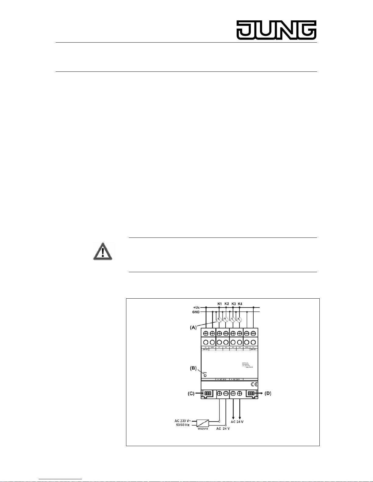
For operation, the 4-channel analog input module needs an external 24 V
power source Art. no. WSSV10.
4. Power supply of connected sensors
• The connected sensors can be supplied from terminals + U
s
and
GND (see fig.
c). These terminals are provided in duplicate and
internally interconnected.
• The total current consumption of all sensors supplied this way must
not exceed 100 mA.
• In the event of overload or short-circuit between +U
S and GND, the
power will be switched off. After removal of the fault, the power is
switched on again automatically.
• Sensors connected can also be supplied externally (e. g. if their
current consumption exceeds 100 mA). In such case, they must be
connected between terminals K1... K4 and GND.
Attention!
U
s
and GND must not be interconnected with the corresponding
terminals of another device.
Connected sensors must not be supplied with power from the
connected KNX/EIB device (Risk of irreparable damage!).
5. Connection
Anschlussbild
2
Page 3

KNX 4-channel analog input module
Ref.-no.: 2214 REG AM
+U
s
: power supply of external transducers
GND : ref. potential for +U
s and inputs K1 ... K4
K1 ... K4 : measured-value inputs
AC 24 V : external power supply voltage
(A) : transducers
(B) : status LED (red)
(C) : system connector, 6-pole, for module connection
(D) : no function
6. Installation of an analog input module
Please observe the following basic rules when installing an analog input
module:
• Replacement of a module (e.g. in case of defect) by one of the
same type can be effected during operation (for this purpose,
disconnect the module from the power supply). After replacement,
the KNX/EIB device will reset after abt. 25 s. All inputs and outputs
of the KNX/EIB device and the modules connected are then reinitialized and reset to their original state.
• Removing or adding modules without adapting their project
configuration and subsequent downloading into the KNX/EIB device
is not allowed as this will result in system failure.
7. Status LED
During commissioning of the module:
On : Module ready for operation (self-test OK).
Quickly blinking : Module initialization in progress
Slowly blinking : Module not configured (in KNX/EIB device)
Off : Module initialized and in operation
Precondition: LED must have been on beforehand!
Normal operation:
On : Module not ready for operation (fault condition)
Off : Module initialized and in operation.
Precondition: LED must have been on beforehand!
Slowly blinking = 1/s; quickly blinking = 2/s
8. Sensors suitable for connection
Connection to a KNX/EIB weather station:
For any of the following transducers, the software provides preset values.
If other sensors are used, the parameters to be set must be determined
beforehand.
Type Use Order no.
Brightness outdoor WS 10H
Twilight outdoor WS 10D
Temperature outdoor WS 10T
Wind outdoor WS 10W
Rain outdoor WS 10R
3
Page 4

KNX 4-channel analog input module
Ref.-no.: 2214 REG AM
Connection to a KNX/EIB analog input:
The parameters to be set for connected sensors must be determined
beforehand.
Type Use Order no.
Brightness outdoor WS 10H
Twilight outdoor WS 10D
Temperature outdoor WS 10T
Wind outdoor WS 10W
Rain outdoor WS 10R
9. Technical Data
Power supply
Supply voltage : AC 24 V ± 10 %
Current consumption : 170 mA max.
Current consumption
on system connector : typically 150 mW
Ambient temperature : -5 °C ... +45 °C
Storage/transport temp. : -25 °C ... +70 °C
Humidity
Ambient/storage/transport : 93 % r.h. max., no
condensation
Protective system : IP 20 as per EN 60529
Installation width : 4 modules / 72 mm
Weight : approx. 150 g
Connections
Inputs, power supply : screw terminals
single-wire : 0.5 mm²
to 4 mm²
stranded wire (without ferrule) : 0.34 mm² to 4 mm²
stranded wire (with ferrule) : 0.14 mm² to 2.5 mm²
Connection to KNX/EIB device : 6-pole system connector
Sensor inputs
Number : 4x analog
Evaluable sensor signals : 0 … 1 V DC, 0 … 10 V DC,
0 … 20 mA, 4 … 20 mA
Voltage measurement impedance : approx. 18 kΩ
Current measurement impedance : approx. 100 Ω
External sensor power supply (+U
s
) : 24 V DC, 100 mA max.
Subject to technical modifications.
4
Page 5

KNX 4-channel analog input module
Ref.-no.: 2214 REG AM
10. Acceptance of guarantee
Our products are under guarantee within the scope of the statutory
provisions.
Please return the unit postage paid to our central service
department giving a brief description of the fault:
ALBRECHT JUNG GMBH & CO. KG
Service-Center
Kupferstr. 17-19
D-44532 Lünen
Service-Line: +49 (0) 23 55 . 80 65 51
Telefax: +49 (0) 23 55 . 80 61 89
E-Mail: mail.vki@jung.de
Technik (allgemein)
Service-Line: +49 (0) 23 55 . 80 65 55
Telefax: +49 (0) 23 55 . 80 62 55
E-Mail: mail.vkm@jung.de
Technik (KNX/EIB)
Service-Line: +49 (0) 23 55 . 80 65 56
Telefax: +49 (0) 23 55 . 80 62 55
E-Mail: mail.vkm@jung.de
The
-Sign is a free trade sign addressed exclusively to the
authorities and does not include any warranty of any properties.
5
 Loading...