

Page 1
4-channel analog input
4-channel analog input
Art. No. : 2214REGA-01
Operating instructions
1 Safety instructions
32551515
J0082551515
1/7
08.11.2017
Page 2
4-channel analog input
2 Device components
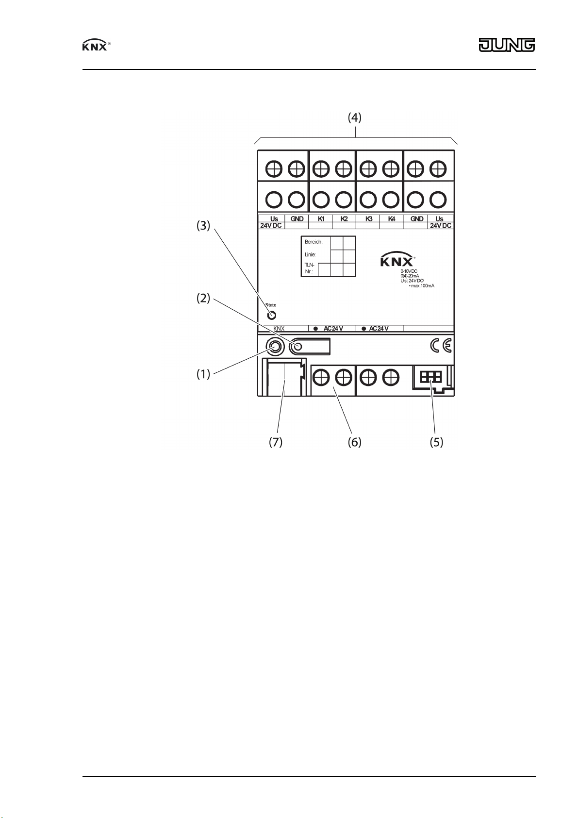
Figure 1: Device components
(1) Programming LED
(2) Programming button
(3) Status LED, three colors (red, orange, green)
(4) Device connection terminals for inputs
(5) Module connection, 6-pin, for connecting an analog input module
(6) Device connection terminal for external supply
(7) KNX connection
3 Function
System information
This device is a product of the KNX system and complies with the KNX directives. Detailed
technical knowledge obtained in KNX training courses is a prerequisite to proper understanding.
The function of this device depends upon the software. Detailed information on loadable software and attainable functionality as well as the software itself can be obtained from the
manufacturer´s product database. Planning, installation and commissioning of the device are
carried out with the aid of KNX-certified software. The latest versions of product database and
the technical descriptions are available on our website.
Intended use
- The 4-off analog input processes measuring data from analog sensors. Up to four freely
combinable analog measurement transducers can be connected.
32551515
J0082551515
2/7
08.11.2017
Page 3
4-channel analog input
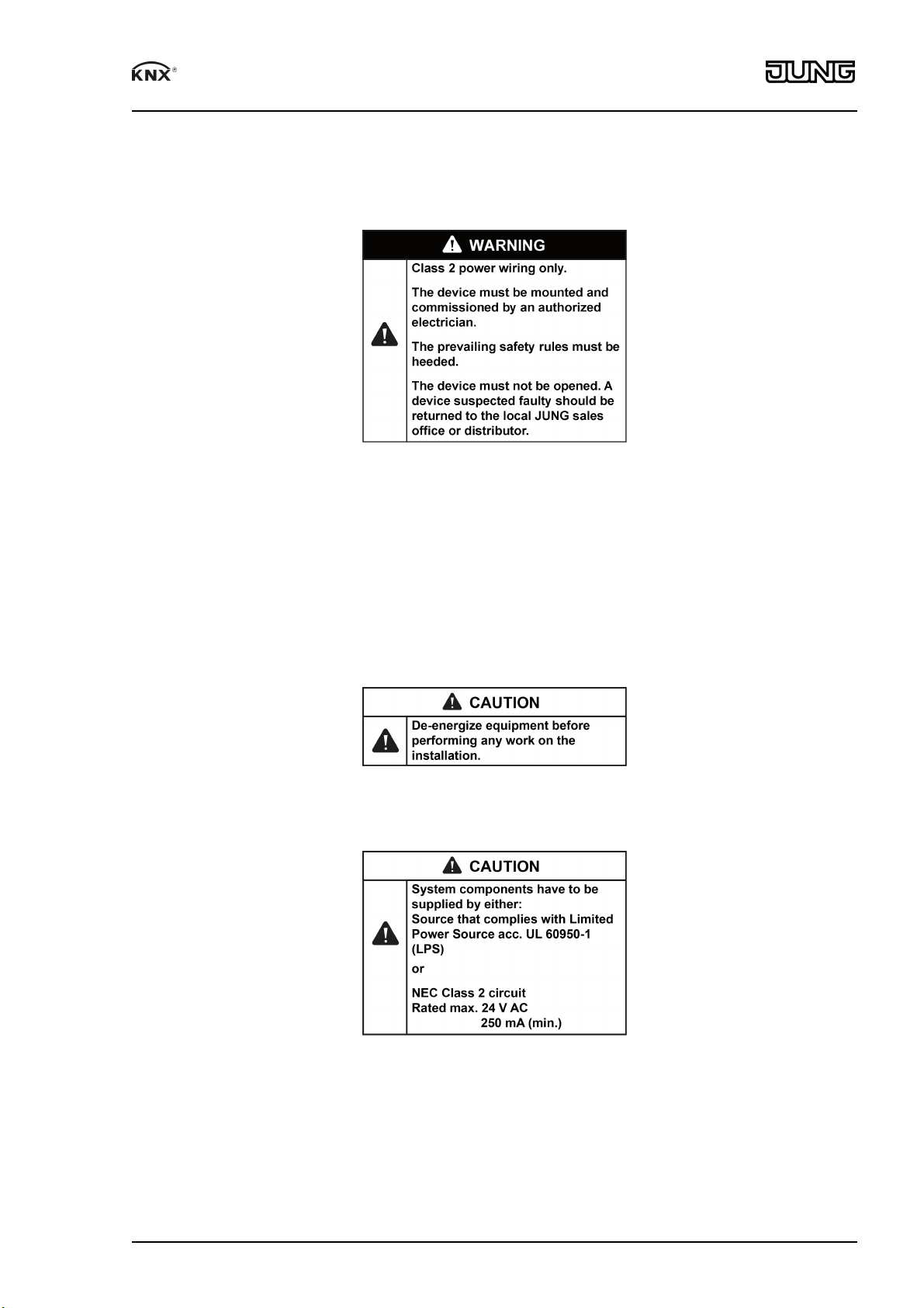
- Operation with NEC Class 2 suitable power supply AC 24 V SELV.
- Installation in small distributors on a DIN rail according to EN 60715.
4 Information for electrically skilled persons
4.1 Mounting and electrical connection
Mounting a 4-off analog input
o Mount the device on a DIN rail with the KNX connection facing downwards.
i An analog input module is only connected to the analog input with the 6-pin system con-
nector (enclosed with the analog input module).
i Use an NEC Class 2 suitable power supply unit AC 24 V SELV for power supply.
32551515
J0082551515
3/7
08.11.2017
Page 4

4-channel analog input
Connecting a 4-off analog input
Figure 2: Device connection
(8) External power supply of the device (NEC Class 2 suitable power supply unit AC 24 V
SELV for power supply)
(9) Bus line (Use only cables which are approved for KNX.)
(10) Measured value inputs K1 ... K4
(11) Reference potential for +Us and inputs K1...K4 (GND)
32551515
J0082551515
4/7
08.11.2017
Page 5
4-channel analog input
(12) Supply of external measurement transducers (+Us)
(13) Measurement transducer (internally supplied)
(14) Measurement transducer (externally supplied)
(15) External power supply of connected sensors
(16) Measurement transducer (supply from external power supply of the device (8) is not per-
mitted)
o Connect device as shown in the connection example (figure 2).
o Connect bus line with device connection terminal.
i Use only cables which are approved for KNX.
i Observe the cable routing! The connection cable must not come into prolonged contact
with elements conducting heat, e.g., a heating pipe or radiator.
Supply of connected sensors
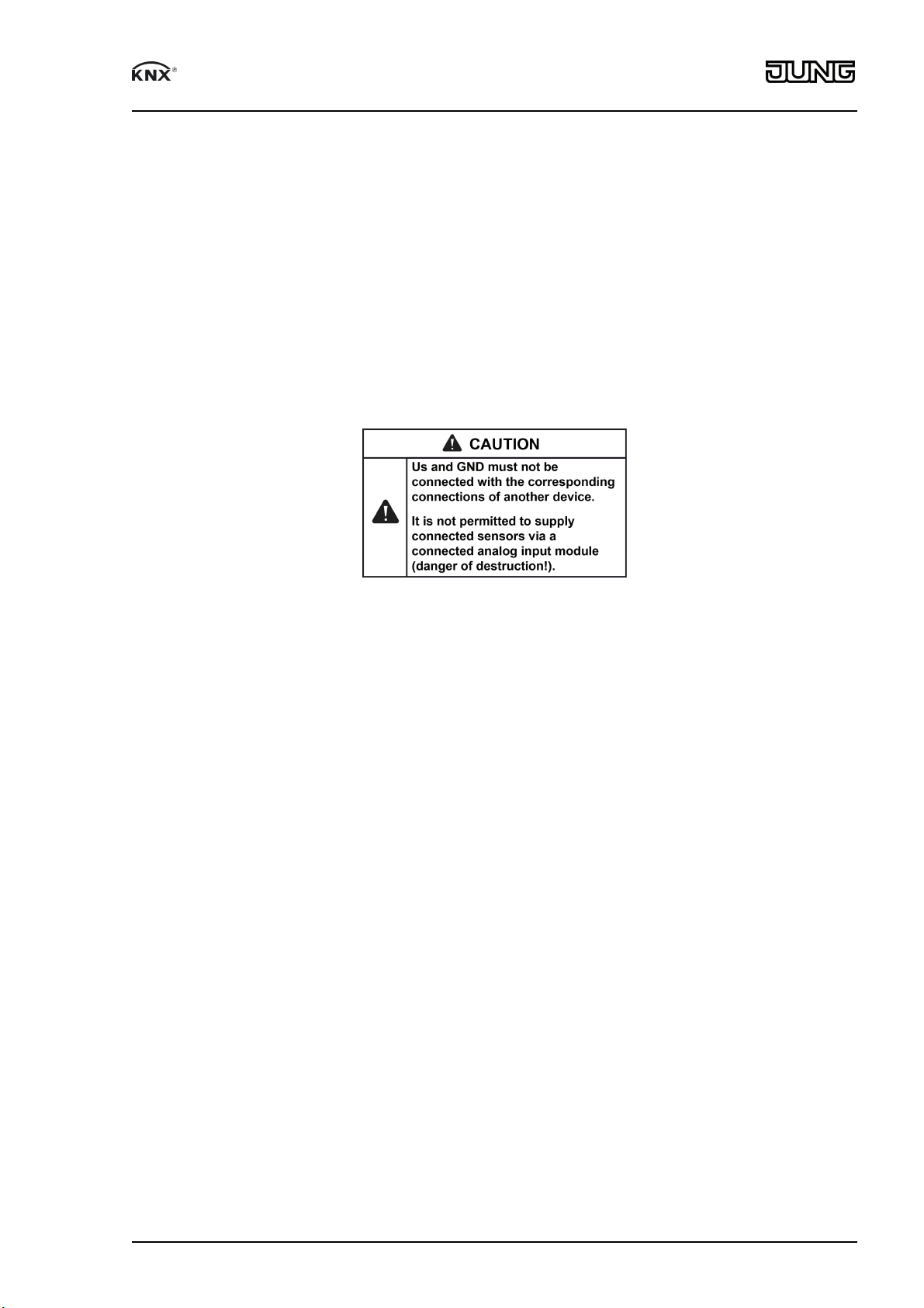
i Connected sensors can be supplied via the terminals +Us and GND of the analog input
module (figure 2). These are provided double and are internally connected with each other
in each case.
i The total power consumption of all sensors supplied in this way must not exceed 100 mA.
i In the case of overload or short-circuit between +Us and GND, the voltage is switched off.
After the fault has been corrected, the voltage automatically switches on again.
Installation of the analog input module
When an analog input module is installed, the following basic rules must be observed:
o A maximum of one analog input module can be connected.
o An analog input module can be replaced with one of the same type, e.g., in the case of a
fault, while the system is running (de-energize the module!). After replacement, the 4-off
analog input will perform a reset after approx. 25 seconds. As a result, all inputs and outputs of the 4-off analog input and the connected modules will be re-initialized and reset to
their original state.
i It is not permitted to remove or add modules without adapting the project design and sub-
sequently downloading to the 4-off analog input, since this leads to malfunctioning of the
system.
4.2 Commissioning
Programming the physical address and application program
o Switch on the external supply voltage.
o Switch on the bus voltage.
o Assign the physical address and note it on the device label.
o Program the application program.
i No programming is possible if no mains voltage is connected.
32551515
J0082551515
5/7
08.11.2017
Page 6

4-channel analog input
5 Appendix
5.1 Status LED
Off No power supply
Orange / on Module scan via analog input
Orange / flashes quickly (2/s) Analog input module scan
Red / flashes slowly (1/s) Error: Undervoltage at the module connection
/ short-circuit Us
Red / flashes quickly (2/s) Error: No project / error in programming
Green / flashes slowly (1/s) Address assignment, module scan completed,
project design OK
Green / flashes quickly (2/s) Parameter download to module
Green / on Module scan completed, everything OK
Disposal
Please consider your local regulation for disposal and electronic waste recycling.
5.2 Technical data
Supply
Power supply AC 24 V
Current consumption max. 250 mA
Ext. sensors (+Us) 24 V DC, max. 100 mA
Module connection 24 V DC, max. 80 mA
KNX
KNX medium TP
Commissioning mode S-mode
Rated voltage KNX DC 21 ... 30V SELV
Ambient conditions
Ambient temperature 23 ... 113°F
(-5 °C ... +45 °C)
Storage/transport temperature -13 ... 158°F
(-25 ... +70 °C)
Relative humidity max. 93%
Housing
Fitting width 72mm / 4modules
Connections
Inputs, supply Screw terminals
Single stranded 20 ... 12 AWG
(0.5 ... 4 mm²)
Finely stranded (without conductor sleeve) 22 ... 12 AWG
(0.34 ... 4 mm²)
Finely stranded (with conductor sleeve) 26 ... 14 AWG
(0.14 ... 2.5 mm²)
Extension module 6-pin system connector
Sensor inputs
Number 4 x analog
Evaluable sensor signals
Voltage signals 0 ... 1 V DC or
0 ... 10 V DC
Current signals 0 ... 20 mA DC or
4 ... 20 mA DC
Impedance sensor signals
Voltage measurement approx. 18 kOhm
Measuring current approx. 100 Ohm
32551515
J0082551515
6/7
08.11.2017
Page 7

4-channel analog input
5.3 Accessories
Brightness Sensor Order No. WS10H-01
Temperature Sensor Order No. WS10T-01
5.4 Warranty
If you have any questions about this product, contact:
Jung USA, Inc.
350 Fifth Avenue, Suite 5220
New York, NY 10118
Phone: +1 800.311.6135
Email: sales@jungcontrols.com
www.jungcontrols.com
For the product warranty, please refer to the attached document.
All rights reserved
©
ALBRECHT JUNG GMBH & CO. KG
Volmestraße 1
58579 Schalksmühle
GERMANY
32551515
J0082551515
7/7
08.11.2017
 Loading...