

Page 1
Control unit 1-10 V, 3-gang
Control unit 1-10 V, 3-gang
Art.-No.: 2193 REG
Operationsmanual
1 Safety instructions
Electrical equipment may only be installed and fitted by electrically skilled persons.
Failure to observe the instructions may cause damage to the device and result in fire and
other hazards.
Danger of electric shock. Device is not suitable for disconnection from supply voltage.
Danger of electric shock. The 1...10 V control voltage is a functional extra-low voltage
(FELV), and can be connected to mains potential. On installing, ensure safe separation to
SELV/PELV systems. In order to disconnect the connected luminaires, disconnect both
the mains voltage and control voltage circuits.
These instructions are an integral part of the product, and must remain with the end
customer.
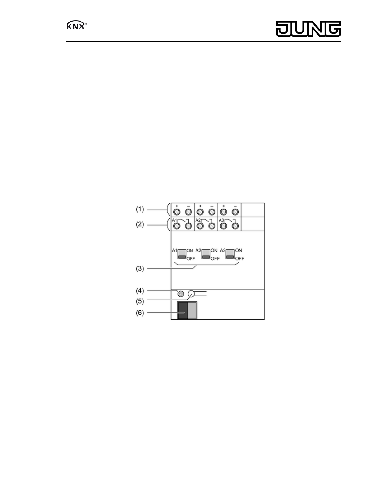
2 Device components
picture 1
(1) Connection for control outputs
(2) Connection for switching outputs
(3) Slide switch/Status indication
(4) Programming LED
(5) Programming button
(6) KNX connection
3 Function
System information
This device is a product of the KNX system and complies with the KNX directives. Detailed
technical knowledge obtained in KNX training courses is a prerequisite to proper
understanding.
The function of this device depends upon the software. Detailed information on loadable
software and attainable functionality as well as the software itself can be obtained from the
manufacturer´s product database. Planning, installation and commissioning of the device are
1/6
82506533
J:0082506533
13.08.2010
Page 2
carried out with the aid of KNX-certified software. The latest versions of product database and
the technical descriptions are available on our website.
Intended use
- Switching and brightness setting for lamps with operating devices with 1-10-V interface
- Mounting on DIN rail according to EN 60715 in distribution boxes
Product characteristics
- Relay switch contact for switching the connected loads
- Manual operation of the relay independently of the bus
- Various L1, L2 and L3 external conductors can be connected.
- No additional power supply necessary
- Feedback of switching state and brightness value
- Switch position display
- Switch-on and dimming behaviour can be set
- Time dimmer can be set
- Time functions: switch-on delay, switch-off delay, staircase lighting timer with run-on time
- Integration into light scenes
4 Operation
Switching relay contacts manually
The status of the relay is reflected by the slide switches (3) on the front of the device (picture 1).
At the same time they can be used for manual operation of the relay outputs sing a suitable
tool.
o Move slide switch to ON position.
Relay contact is closed, load is switched on.
o Move slide switch to OFF position.
Relay contact is open, load is switched off.
i The position of the slide switch immediately reflects the status of the relay, regardless of
whether the output is in NO or NC mode of operation.
i Manual switching of the relays is independent of the bus. Thus in case of manual switching
there will be no feedback via the bus.
i Outputs disabled via software can still be switched manually.
5 Information for electrically skilled persons
5.1 Fitting and electrical connection
DANGER!
Electrical shock when live parts are touched.
Electrical shocks can be fatal.
Before carrying out work on the device or load, disengage all the
corresponding circuit breakers. Cover up live parts in the working environment.
Fitting the device
Observe the temperature range. Ensure adequate cooling.
o Mount device on DIN rail. Output terminals must be at the top.
2/6
82506533
J:0082506533
13.08.2010
Control unit 1-10 V, 3-gang
Page 3

Connecting the device
picture 2
(7) Lamp operating device with 1-10 V interface
Control cable: appropriate type, cross-section and routing for the specifications for mains
voltage cables. 1-10 V and mains voltages wires can be run together in a cable,
e.g. NYM 5x1.5 mm².
Only use lamp operating devices that are of the same type, the same power level, and from the
same manufacturer. Otherwise there may be differences in brightness between the individual
lamps.
The maximum number of lamp operating devices that can be connected is a function of the sum
of the control voltages that feed these devices.
i Electronic lamp operating devices generate high current spikes when they are switched on,
that can result in sticking of the relay contacts. Note switch-on currents. In the case of
loads with high switch-on current, use switch-on current limiter or separate load protection.
o Connect the device according to the connection diagram (picture 2).
o Connect load operating devices with protective earth conductor in accordance with the
manufacturer's specifications.
o If multiple miniature circuit breakers supply dangerous voltages to the device or load,
couple the miniature circuit breakers or label them with a warning, to ensure release is
guaranteed.
Installing the cover
It is necessary to install a cover to protect the bus connection against hazardous voltages in the
connection area.
3/6
82506533
J:0082506533
13.08.2010
Control unit 1-10 V, 3-gang
Page 4

picture 3: Installing the cover
o Route the bus cable towards the rear.
o Install cover on top of the bus terminal so that it snaps into place (picture 3).
Removing the cover
picture 4: Removing the cover
o Press the cover to the side and pull it off (picture 4).
5.2 Commissioning
Load the address and the application software
o Switch on the bus voltage
o Assign physical addresses and load application software into the device.
o Note the physical address on the device label.
4/6
82506533
J:0082506533
13.08.2010
Control unit 1-10 V, 3-gang
Page 5

6 Appendix
6.1 Technical data
KNX
KNX medium TP 1
Commissioning mode S mode
Rated voltage KNX DC 21 ... 32 V SELV
Power consumption KNX max. 240 mW
Connection mode KNX Connection terminal
Ambient temperature -5 ... +45 °C
Storage/transport temperature -25 ... +70 °C
Control outputs
Control voltage 1 ... 10 V
Control current per output max. 100 mA
Cable length max. 500 m (0.5mm2)
Switching outputs
Contact type µ contact
Switching voltage AC 250 / 400 V
Switching current 230 V AC 1 16 A
Switching current 230 V AC 3 10 A
Switching current 400 V AC 1 10 A
Switching current 400 V AC 3 6 A
Fluorescent lamps 10 AX
Switching voltage DC DC 12 ... 24 V
Switching current DC 16 A
Minimum switching current 100 mA
Switch-on current 150 µs 400 A
Switch-on current 600 µs 200 A
Ohmic load 3680 W
Capacitive load 10 A / 140 µF
Lamp loads
Incandescent lamps 2500 W
HV halogen lamps 2500 W
LV halogen lamps with inductive transformer 1200 VA
LV halogen lamps with Tronic transformer 1500 W
Fluorescent lamps T5/T8
uncompensated 2500 W
parallel compensated 1300 W / 140 µF
Duo circuit 2300 W / 140 µF
Compact fluorescent lamps
uncompensated 2500 W
parallel compensated 1300 W / 140 µF
Mercury vapour lamps
uncompensated 2000 W
parallel compensated 2000 W / 140 µF
Connection
Single stranded 0.5 ... 4 mm²
finely stranded without conductor sleeve 0.34 ... 4 mm²
finely stranded with conductor sleeve 0.14 ... 2.5 mm²
Fitting width 72 mm / 4 modules
6.2 Accessories
Connection cover Art.-No.: 2050 K
5/6
82506533
J:0082506533
13.08.2010
Control unit 1-10 V, 3-gang
Page 6

6.3 Warranty
We reserve the right to make technical and formal changes to the product in the interest of
technical progress.
We provide a warranty as provided for by law.
Please send the unit postage-free with a description of the defect to our central customer
service office:
ALBRECHT JUNG GMBH & CO. KG
Service Center
Kupferstr. 17-19
D-44532 Lünen
Service-Line: +49 (0) 23 55 . 80 65 51
Telefax: +49 (0) 23 55 . 80 61 89
mail.vki@jung.de
Technik (Allgemein)
Service-Line: +49 (0) 23 55 . 80 65 55
Telefax: +49 (0) 23 55 . 80 62 55
mail.vkm@jung.de
Technik (KNX)
Service-Line: +49 (0) 23 55 . 80 65 56
Telefax: +49 (0) 23 55 . 80 62 55
mail.vkm@jung.de
The Πsymbol is a free trade symbol, which is solely intended for the authorities and does not
guarantee any properties.
ALBRECHT JUNG GMBH & CO. KG
Volmestraße 1
D-58579 Schalksmühle
Telefon: +49.23 55.8 06-0
Telefax: +49.23 55.8 06-1 89
E-mail: mail.info@jung.de
Internet: www.jung.de
www.jung-katalog.de
6/6
82506533
J:0082506533
13.08.2010
Control unit 1-10 V, 3-gang
 Loading...